Embed Size (px)
Citation preview
AQORD *LINK AQORD *LINK/LE
User Manual
Valid for firmware version 7.0 and newer

TABLE OF CONTENT
1. INTRODUCTION 2. Security instructions 3. Product description 4. Enclosed accessories 5. Specifications 6. AQORD main functions
6.1. Encoding / Decoding 6.2. Full duplex 6.3. Streaming / Recording 6.4. Dual Streaming
7. Installation 7.1. List of connections AQORD *LINK 1C/2C 7.2. List of connections AQORD *LINK/LE
8. Power on / off 9. Web interface
9.1. “Home” page 9.2. “System administration” pages
9.2.1. “Shutdown/restart” 9.2.2. “Usage statistics” 9.2.3. “Machine Name” 9.2.4. “Password” 9.2.5. “Network settings” 9.2.6. “Wifi Access Point” 9.2.7. “Date & Time” 9.2.8. “Status” 9.2.9. “Version” 9.2.10. “Update” 9.2.11. “Licence” 9.2.12. “Developer tools”
9.3. “Profile” management pages 9.3.1. “Channel Configuration” 9.3.2. “Profile List” 9.3.3. “Profile settings” page 9.3.4. Export page 9.3.5. Import page 9.3.6. Report LOG page
9.4. User disk space 9.4.1. “Storage Status” page 9.4.2. “Storage Area” page
10. Local interface description 10.1. “AQORD *LINK Starting” screen 10.2. Default screen 10.3. “Profile” screen
10.3.1. Description 10.3.2. Confirmation of profile starting action
10.4. “administration” screen 10.4.1. Restart screen 10.4.2. Shutdown screen 10.4.3. LCD Backlight/Contrast screen 10.4.4. Fan screen

10.4.5. Temperatures screen 10.4.6. HDD user area screen 10.4.7. SDI statuts screen 10.4.8. ETH0 connection screen 10.4.9. IP address screen 10.4.10. Sub mask screen 10.4.11. Gateway screen
10.5. Factory parameter screen 10.5.1. Minimal restoration 10.5.2. Complete restoration
10.6. Definition of LED Status 11. Managing profiles
11.1. Define a new profile 11.2. Modify profile parameters 11.3. Duplicate a Profile 11.4. Delete a profile
12. User disk area : file transfer 13. Software update 14. Forward Error Correction
14.1. Introduction 14.2. How to monitor packets lost and packets recovered 14.3. Configuration examples
15. XML API 15.1. General presentation 15.2. How to Use 15.3. Commands example
15.3.1. “start_profile” 15.3.2. “stop_profile” 15.3.3. “get_profile_list” 15.3.4. “restart” 15.3.5. “shutdown” 15.3.6. “get_hardware_status” 15.3.7. “set_ip” 15.3.8. “Trigger internal event”
16. Typical applications 16.1. Typical IP internet contribution 16.2. Typical IP satellite contribution 16.3. Dual Streaming 16.4. Duplex application : academic application example 16.5. Point to multipoints contribution application example 16.6. Octoshape Point to multipoints contribution application example
17. Glossary

1. INTRODUCTION This manual explains how to use and install an AQORD products:
AQORD *LINK AQORD *LINK/LE
This manual is for AQORD users.
The AQORD is part of a system that can be used to encode, decode, store, replay and transmit MPEG2 Transport Stream (H264/AVC codec) to other equipment (Satellite, internet provider, IP network transmission) through Internet Protocols.

2. Security instructions Notice
The information contained in this document is subject to change without notice. DIGIGRAM shall not be liable for errors contained herein or for incidental or consequential damages in connection with the furnishing, performance, or use of this material.
General instructions for security
The device is manufactured in accordance with today’s technology and with respect to security regulations.
The encoder must not be opened. Top removal or disassembly of mechanical parts results in the invalidation of the product warranty.
The top housing of the AQORD product should always be in place during normal operation. Top removal should be performed only by a qualified person.
You, as the user of the product, should follow these warnings and all other safety precautions necessary for the safe operation of the equipment in your operating environment.
Please make sure to read the whole User’s manual before connecting AQORD equipment. This manual is part of the device and is delivered with it. Please refer to and respect safety and security precautions.
The electrical safety hazards should not be ignored, as they are as great as other electrical systems operating from AC power lines. The voltages involved and the current available have the potential to cause fatal electric shock. Although the AQORD product is compliant to CE electrical requirements and additional safety features have been included in their design, the following safety precautions should be noted and observed under the control of the responsible authority:
1. Do not remove top cover of the AQORD product. 2. The Mains power cord is connected to the power source by an IEC connector that can be used to
disconnect the AQORD from the Mains power and must be kept accessible to the user at all times. AQORD *LINK Product required two Mains power cords as it is equipped with a redundant power supply. Both must be removed to disconnect the AQORD from the Mains power.
3. The mains cord must be plugged in a socket comprising an Earth connection. The unit must not be disconnected from the Earth as it may impair the electrical protection and render the equipment dangerous.
The User must observe the safety precautions listed below to ensure the safety of personnel and equipment.
Do not operate in explosive atmospheres
Do not operate the equipment in the presence of flammable gases and fumes. The use of equipment in this environment constitutes a danger to plant and personnel.
Do not substitute parts or modify equipment
Introducing any substitute parts not provided by DIGIGRAM invalidates warranty and poses an additional risk. It is forbidden to install substitute boards or perform any equipment modification whatsoever without the prior approval of DIGIGRAM..
Environment
Do not operate the device in an uncontrolled environment where temperature is:
AQORD *LINK: below 0°C (32°F) or above 50°C (122°F), AQORD *LINK/LE: below 10°C (50°F) or above 35°C (95°F),
as this will damage the equipment. Do not allow liquid to enter the equipment, accidentally or otherwise. Ventilation holes are sized for correct air convection, they protect the equipment from overheating, do not cover the ventilation holes at any time.

Warning The system must be plugged to electrical equipment, which conforms to the country norms in use (France – NFC 15100). The electrical equipment must be fitted out with protections over intensity, over voltage, ground plug defaults All equipment connected to the AQORD should be in accordance with EN 609501. Power supply plug is used as safety device. The base of the socket must be placed next to the equipment and be easily accessible. Keep air intakes free of any obstruction to avoid any risk of over heating. When system is open, do not perform any other modifications except from those from user’s manual. To avoid personal injury or equipment damage, turn power off before performing any technical support.
Under certain conditions, dangerous voltages may exist even with power cable removed. to avoid injuries, always disconnect power and discharge circuits before touching them. If battery is replaced with different battery type, there may be a risk of explosion. Please recycle old batteries as directed by national environmental protection regulation.
CE Notice (European Community)
Marking a system with the “CE” symbol indicates compliance of that system to the EMC and Low Voltage directives of the European Community. A system with the CE marking meets or exceeds the following technical standards:
EN 55022 “Limits and methods of measurement of radio interference characteristics of information technology equipment,” Class A.
EN 6100062 “Electromagnetic compatibility Generic immunity standard
Part 2: Residential, commercial, and light industry.”
EN 6100032 “Limits for harmonic currents emissions’’
EN 6100033 ‘’ Limitation of voltage fluctuation and flickers in low voltage supply systems
EN 6100042 “Limits and methods of measurement Section 2: electrostatic discharge immunity test”
EN 6100043 “Limits and methods of measurement – Section 3: Radiated radiofrequency, electromagnetic field immunity test”
EN 6100044 “Limits and methods of measurement Section 4: Electrical fast transient / burst immunity test’’
EN 6100045 “Limits and methods of measurement Section 5: Surge immunity test”
EN 6100046 “Limits and methods of measurement Section 6: immunity to conducted disturbances, induced by radiofrequency fields”
EN 6100048 ‘‘Limits and methods of measurement Section 8: Power frequency magnetic field immunity test’’
EN 61000411 “Limits and methods of measurement Section 11: Voltage dips, short interruptions as voltage variations immunity tests”
ENV 50204 ‘’ Radiated electromagnetic field from digital radio telephones immunity test.’’
EN 609501 (2006) “Safety of information technology equipment, including electrical business equipment.”
In accordance with European Community directives, a “Declaration of Conformity” has been made and is available by request at DIGIGRAM – 82 allée Galilée 38330 Montbonnot SaintMartin FRANCE.
3. Product description AQORD products are HD and SD hardware video encoder, decoder, recoder using the H.264/AVC codec.
The AQORD product line includes 3 products:
AQORD *LINK 1C : 1 channel AQORD *LINK 2C : 2 channels AQORD *LINK/LE : 1 channel
Option can be added to these products:
AQORDOPT/FEC : FEC option, Pro Mpeg FEC CoP3 standard Furthermore, OTT streaming capability option can be added to AQORD *LINK products
AQORDOPT/SWENC: Software encoder option. This option enables software encoding capability to AQORD *LINK 1C/2C for OTT distribution applications (Video on mobile phone, tablet, PC and connected TV). Video codecs available: H.264. Audio codec: AAC series and MPEG1 Layer2. Container format: MPEGTS, HTTP Live Streaming, RTMP, Adaptive Bitrate… (to use this option refer to AQILIM user manual).
Devices form factor is 19'' width and 1RU height. It is rack mountable in a 19" rack.
On the rack side, a label identifies the product. The label details:
The serial number The commercial reference
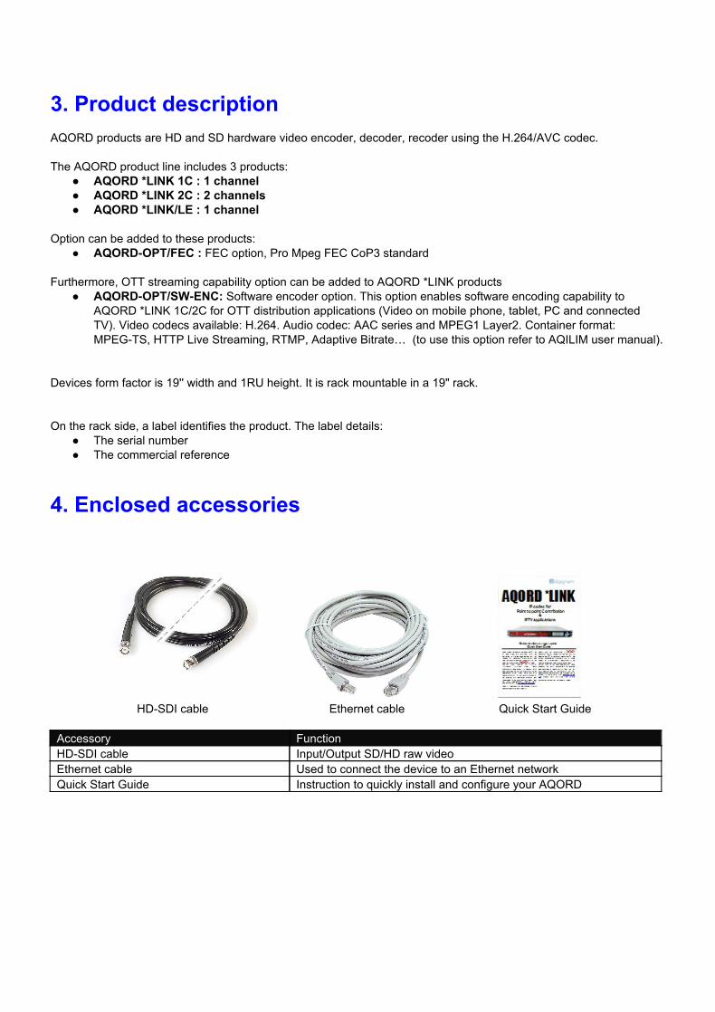
4. Enclosed accessories
HDSDI cable Ethernet cable Quick Start Guide
Accessory Function HDSDI cable Input/Output SD/HD raw video Ethernet cable Used to connect the device to an Ethernet network Quick Start Guide Instruction to quickly install and configure your AQORD
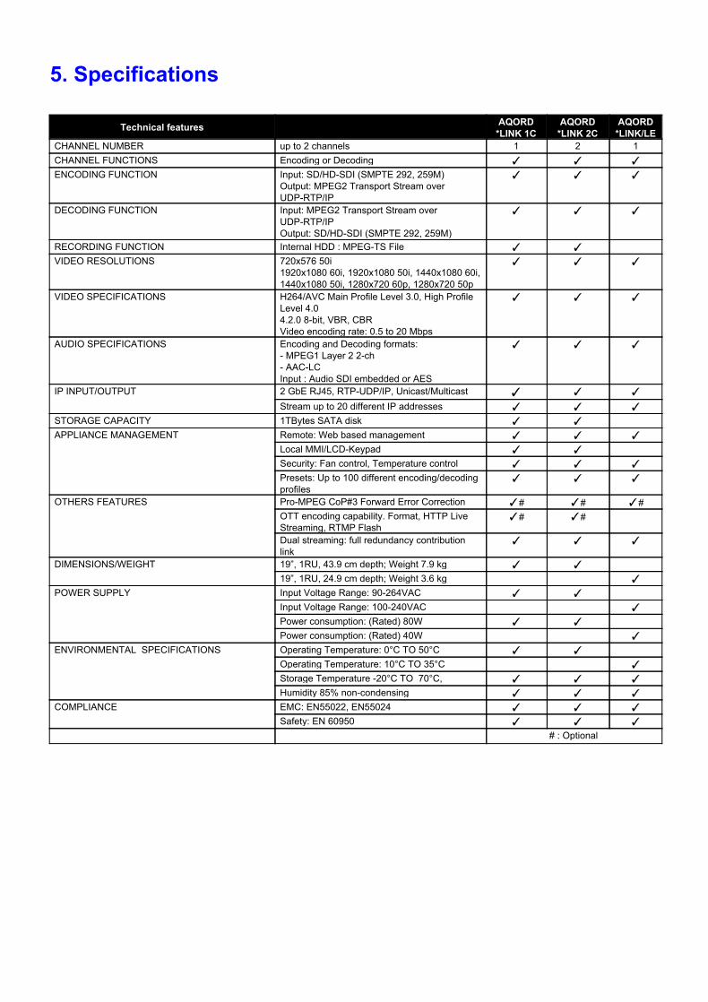
5. Specifications
Technical features Descriptions AQORD *LINK 1C
AQORD *LINK 2C
AQORD *LINK/LE
CHANNEL NUMBER up to 2 channels 1 2 1 CHANNEL FUNCTIONS Encoding or Decoding ENCODING FUNCTION Input: SD/HDSDI (SMPTE 292, 259M)
Output: MPEG2 Transport Stream over UDPRTP/IP
DECODING FUNCTION Input: MPEG2 Transport Stream over UDPRTP/IP Output: SD/HDSDI (SMPTE 292, 259M)
RECORDING FUNCTION Internal HDD : MPEGTS File VIDEO RESOLUTIONS 720x576 50i
1920x1080 60i, 1920x1080 50i, 1440x1080 60i, 1440x1080 50i, 1280x720 60p, 1280x720 50p
VIDEO SPECIFICATIONS H264/AVC Main Profile Level 3.0, High Profile Level 4.0 4.2.0 8bit, VBR, CBR Video encoding rate: 0.5 to 20 Mbps
AUDIO SPECIFICATIONS Encoding and Decoding formats: MPEG1 Layer 2 2ch AACLC Input : Audio SDI embedded or AES
IP INPUT/OUTPUT
2 GbE RJ45, RTPUDP/IP, Unicast/Multicast Stream up to 20 different IP addresses
STORAGE CAPACITY 1TBytes SATA disk APPLIANCE MANAGEMENT
Remote: Web based management Local MMI/LCDKeypad Security: Fan control, Temperature control Presets: Up to 100 different encoding/decoding profiles
OTHERS FEATURES
ProMPEG CoP#3 Forward Error Correction # # # OTT encoding capability. Format, HTTP Live Streaming, RTMP Flash
# #
Dual streaming: full redundancy contribution link
DIMENSIONS/WEIGHT 19”, 1RU, 43.9 cm depth; Weight 7.9 kg 19”, 1RU, 24.9 cm depth; Weight 3.6 kg
POWER SUPPLY
Input Voltage Range: 90264VAC Input Voltage Range: 100240VAC Power consumption: (Rated) 80W Power consumption: (Rated) 40W
ENVIRONMENTAL SPECIFICATIONS
Operating Temperature: 0°C TO 50°C Operating Temperature: 10°C TO 35°C Storage Temperature 20°C TO 70°C, Humidity 85% noncondensing
COMPLIANCE
EMC: EN55022, EN55024 Safety: EN 60950
# : Optional
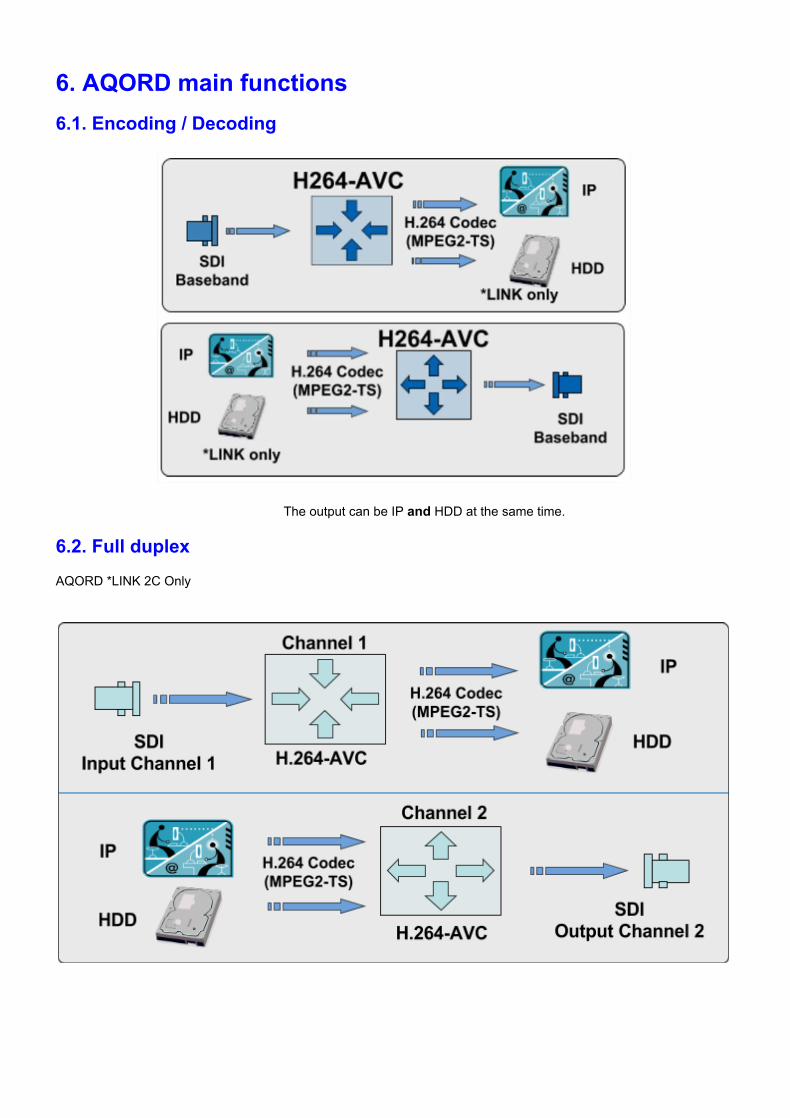
6. AQORD main functions 6.1. Encoding / Decoding
The output can be IP and HDD at the same time.
6.2. Full duplex AQORD *LINK 2C Only
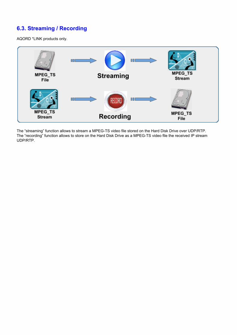
6.3. Streaming / Recording AQORD *LINK products only.
The “streaming” function allows to stream a MPEGTS video file stored on the Hard Disk Drive over UDP/RTP. The “recording” function allows to store on the Hard Disk Drive as a MPEGTS video file the received IP stream UDP/RTP.
6.4. Dual Streaming Mission critical video transport One objective of broadcasters while deploying their IP infrastructure is to achieve the robustness of synchronous telecom or satellite networks on private leased lines while reducing significantly the corresponding production costs. The experience gained from existing IP infrastructures proved that IP network disturbances are of a different nature when occurring inside the Telco backbone infrastructure or during the “Last Mile” path (i.e. near/inside the broadcasters premises). So it is essential for the broadcaster to choose an appropriate operation strategy for each different type of transport he will use, such as fully managed networks using QoS or “Best effort” networks (Internet, Wireless 3G/4G and Wifi).
AQORD encoders/decoders implement FEC (Forward Error Correction) and now “Dual Streaming” to secure the transmission in order to meet Broadcasters and Telcos IP transport strategies.
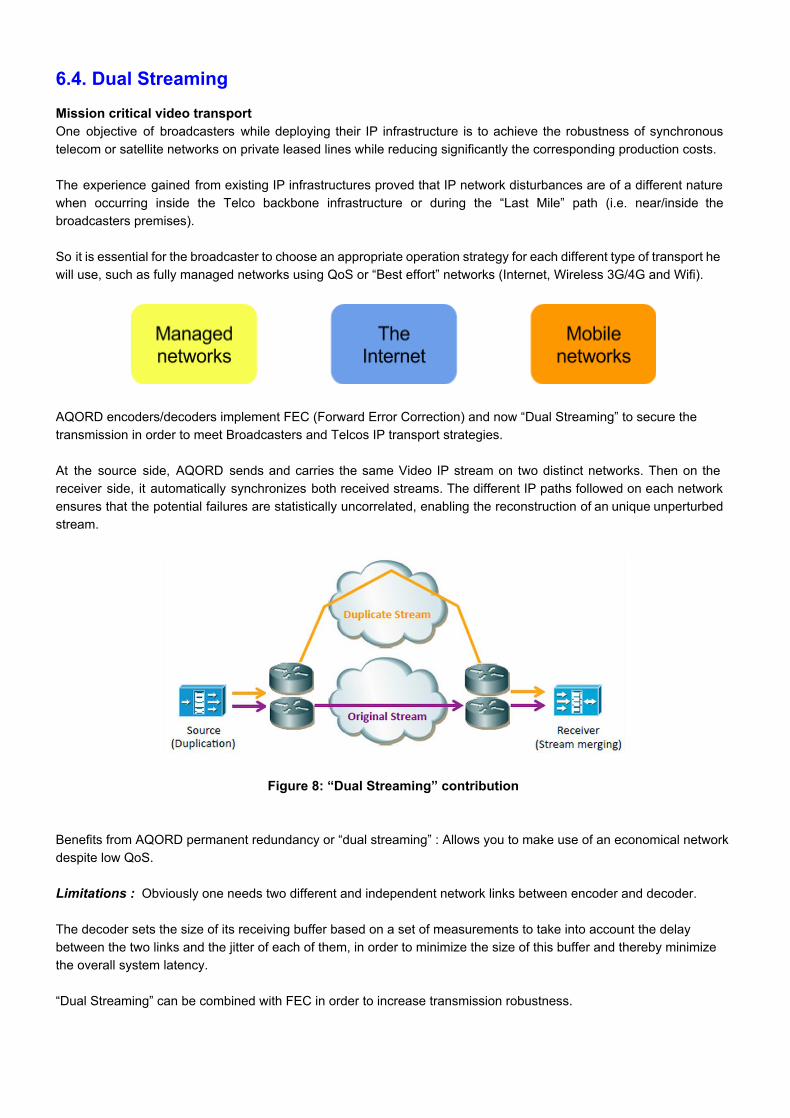
At the source side, AQORD sends and carries the same Video IP stream on two distinct networks. Then on the receiver side, it automatically synchronizes both received streams. The different IP paths followed on each network ensures that the potential failures are statistically uncorrelated, enabling the reconstruction of an unique unperturbed stream.
Figure 8: “Dual Streaming” contribution Benefits from AQORD permanent redundancy or “dual streaming” : Allows you to make use of an economical network despite low QoS. Limitations : Obviously one needs two different and independent network links between encoder and decoder. The decoder sets the size of its receiving buffer based on a set of measurements to take into account the delay between the two links and the jitter of each of them, in order to minimize the size of this buffer and thereby minimize the overall system latency. “Dual Streaming” can be combined with FEC in order to increase transmission robustness.
7. Installation Refer to the Quick Start Guide provided with the AOQRD to proceed to the cabling.
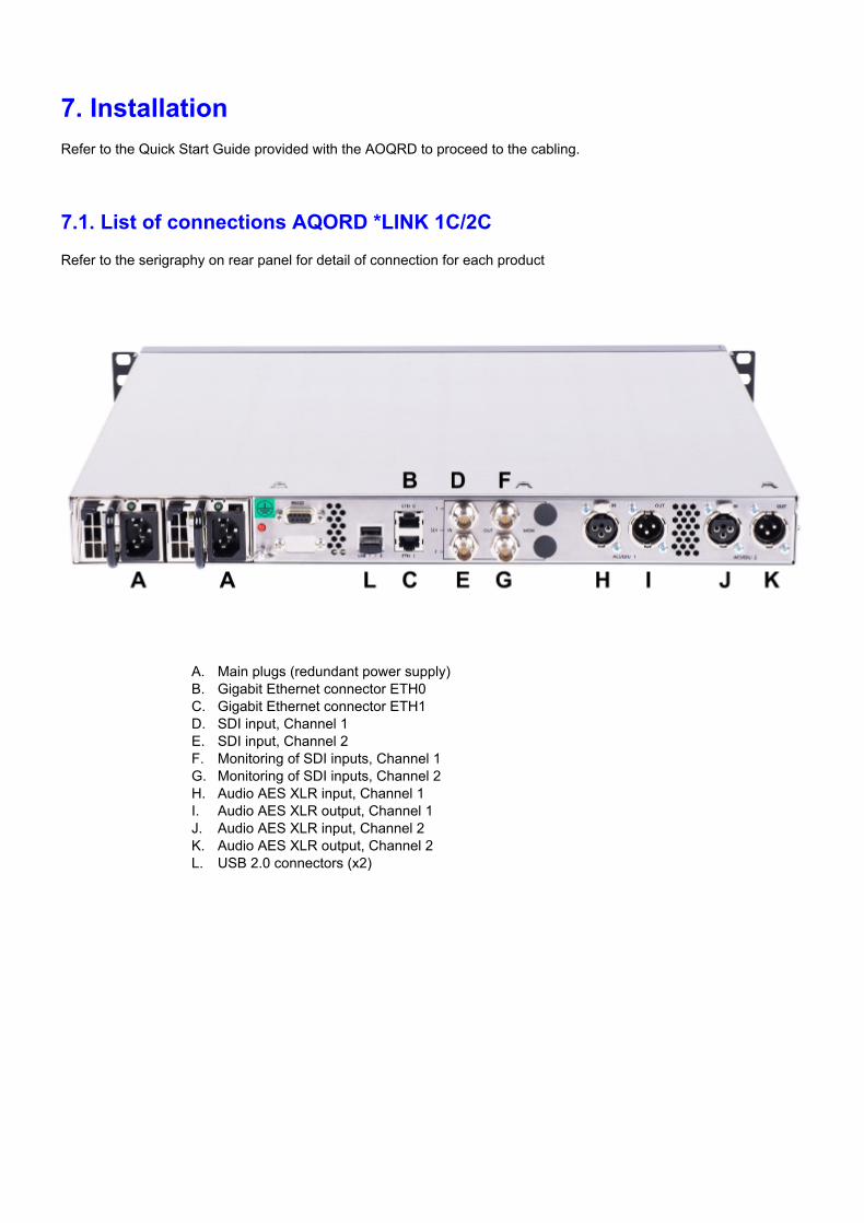
7.1. List of connections AQORD *LINK 1C/2C Refer to the serigraphy on rear panel for detail of connection for each product
A. Main plugs (redundant power supply) B. Gigabit Ethernet connector ETH0 C. Gigabit Ethernet connector ETH1 D. SDI input, Channel 1 E. SDI input, Channel 2 F. Monitoring of SDI inputs, Channel 1 G. Monitoring of SDI inputs, Channel 2 H. Audio AES XLR input, Channel 1 I. Audio AES XLR output, Channel 1 J. Audio AES XLR input, Channel 2 K. Audio AES XLR output, Channel 2 L. USB 2.0 connectors (x2)
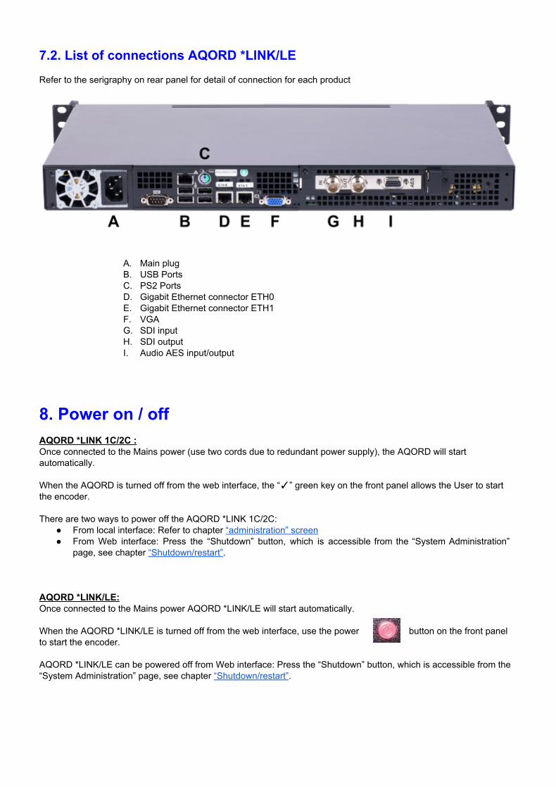
7.2. List of connections AQORD *LINK/LE Refer to the serigraphy on rear panel for detail of connection for each product
A. Main plug B. USB Ports C. PS2 Ports D. Gigabit Ethernet connector ETH0 E. Gigabit Ethernet connector ETH1 F. VGA G. SDI input H. SDI output I. Audio AES input/output
8. Power on / off AQORD *LINK 1C/2C : Once connected to the Mains power (use two cords due to redundant power supply), the AQORD will start automatically. When the AQORD is turned off from the web interface, the “” green key on the front panel allows the User to start the encoder. There are two ways to power off the AQORD *LINK 1C/2C:
From local interface: Refer to chapter “administration” screen From Web interface: Press the “Shutdown” button, which is accessible from the “System Administration”
page, see chapter “Shutdown/restart”. AQORD *LINK/LE: Once connected to the Mains power AQORD *LINK/LE will start automatically. When the AQORD *LINK/LE is turned off from the web interface, use the power button on the front panel to start the encoder. AQORD *LINK/LE can be powered off from Web interface: Press the “Shutdown” button, which is accessible from the “System Administration” page, see chapter “Shutdown/restart”.

9. Web interface The web interface is accessible from any Ethernet interfaces (ETH0 and ETH1). By default (factory setting) ETH0 IP address is 192.168.0.1. Enter the following IP address in your web browser to reach to web interface:
http://192.168.0.1 (factory setting) If the configuration has changed and you need to revert to factory settings, see the chapter “Factory parameter screen”. IP addresses can be configured by different means :
From the web interface: refer to the chapter “Network settings” From front panel interface: refer to the chapter “ETH0 connection screen” (AQORD *LINK 1C/2C only) Using display and keyboard: refer to the “Quick Start Guide” (AQORD *LINK/LE only)
Note: use "admin" for login and "digigram38" for password (factory setting).
9.1. “Home” page This page shows the type of AQORD product which the browser is connected to, namely: "AQORD *LINK 1C / 2C / LE”.
It allows quick access to various settings of the machine:
Profile administration: “Profile”. User hard disk space and video files: “Storage”. System parameters: “System”.

9.2. “System administration” pages
9.2.1. “Shutdown/restart” This page allows you to restart or shutdown the AQORD. Restarting AQORD is required when changing network settings (see chapter “Network settings”).
9.2.2. “Usage statistics” This page displayed some statistic information like: Number of started profiles, lost packets, recovery packets, late packets and so one. This page is mainly intended to give you some measurement information that help understanding the quality of your contribution link. Below are the available information for each contribution profile (mainly information from decoding profile):
"Received Packets": Number of received packets "Lost packets": Number of lost packets:
required RTP network protocol (UDP protocol doesn’t allow to know lost packets) If FEC is active. “Lost packets” means number of packets that could not be recovered by FEC
algorithm "Reordered Packets" : Number of disorder packet received
required RTP network protocol (UDP protocol doesn’t allow to know packet order) "Recovered Packets" : Means number of packets recovered by FEC algorithm. "Input Bitrate" : input stream bitrate received by a decoding profile. "Duplicated Packets" : Duplicate packets received. When “dual link” capability is used (link redundancy)
pourcentage should be 100% if not packets is lost. "Duplicated Packets Delay" : Max Delay between the two links when “dual link” capability is used. "RESET" button: reset all the counters above. "Output Bitrate" : output stream bitrate sent by a encoding profile.
Global parameters:
"ETHx Input Bitrate" : IP bitrate received on Ethernet interface ETHx "ETHx Output Bitrate" : IP bitrate sent on Ethernet interface ETHx
9.2.3. “Machine Name” An arbitrary name can be assigned to the AQORD. This name then appears in the Internet browser tab and in the banner at the top of the page.
9.2.4. “Password” The AQORD login is factory set to: "admin" and the password to “digigram38”. This page allows the user to change the password.
To change the password, follow the instructions below:
1. Enter the factory settings or your own login and password. 2. Enter the new password and confirm the new password. 3. Click on “Save Setting” button to save these new parameters.
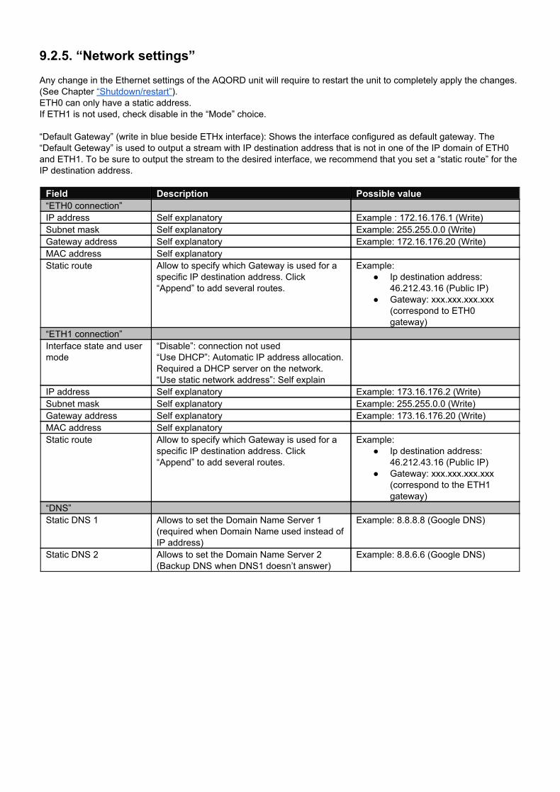
9.2.5. “Network settings” Any change in the Ethernet settings of the AQORD unit will require to restart the unit to completely apply the changes. (See Chapter “Shutdown/restart”). ETH0 can only have a static address. If ETH1 is not used, check disable in the “Mode” choice. “Default Gateway” (write in blue beside ETHx interface): Shows the interface configured as default gateway. The “Default Geteway” is used to output a stream with IP destination address that is not in one of the IP domain of ETH0 and ETH1. To be sure to output the stream to the desired interface, we recommend that you set a “static route” for the IP destination address. Field Description Possible value “ETH0 connection” IP address Self explanatory Example : 172.16.176.1 (Write) Subnet mask Self explanatory Example: 255.255.0.0 (Write) Gateway address Self explanatory Example: 172.16.176.20 (Write) MAC address Self explanatory Static route Allow to specify which Gateway is used for a
specific IP destination address. Click “Append” to add several routes.
Example: Ip destination address:
46.212.43.16 (Public IP) Gateway: xxx.xxx.xxx.xxx
(correspond to ETH0 gateway)
“ETH1 connection” Interface state and user mode
“Disable”: connection not used “Use DHCP”: Automatic IP address allocation. Required a DHCP server on the network. “Use static network address”: Self explain
IP address Self explanatory Example: 173.16.176.2 (Write) Subnet mask Self explanatory Example: 255.255.0.0 (Write) Gateway address Self explanatory Example: 173.16.176.20 (Write) MAC address Self explanatory Static route Allow to specify which Gateway is used for a
specific IP destination address. Click “Append” to add several routes.
Example: Ip destination address:
46.212.43.16 (Public IP) Gateway: xxx.xxx.xxx.xxx
(correspond to the ETH1 gateway)
“DNS” Static DNS 1 Allows to set the Domain Name Server 1
(required when Domain Name used instead of IP address)
Example: 8.8.8.8 (Google DNS)
Static DNS 2 Allows to set the Domain Name Server 2 (Backup DNS when DNS1 doesn’t answer)
Example: 8.8.6.6 (Google DNS)
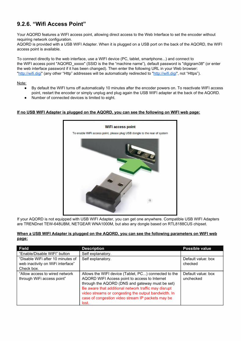
9.2.6. “Wifi Access Point” Your AQORD features a WIFI access point, allowing direct access to the Web Interface to set the encoder without requiring network configuration. AQORD is provided with a USB WIFI Adapter. When it is plugged on a USB port on the back of the AQORD, the WIFI access point is available. To connect directly to the web interface, use a WIFI device (PC, tablet, smartphone...) and connect to the WIFI access point "AQORD_xxxxx" (SSID is the the “machine name”), default password is "digigram38" (or enter the web interface password if it has been changed). Then enter the following URL in your Web browser: "http://wifi.digi" (any other “Http” addresses will be automatically redirected to "http://wifi.digi", not “Https”). Note:
By default the WIFI turns off automatically 10 minutes after the encoder powers on. To reactivate WIFI access point, restart the encoder or simply unplug and plug again the USB WIFI adapter at the back of the AQORD.
Number of connected devices is limited to eight. If no USB WIFI Adapter is plugged on the AQORD, you can see the following on WIFI web page:
If your AQORD is not equipped with USB WIFI Adapter, you can get one anywhere. Compatible USB WIFI Adapters are TRENDnet TEW648UBM, NETGEAR WNA1000M, but also any dongle based on RTL8188CUS chipset. When a USB WIFI Adapter is plugged on the AQORD, you can see the following parameters on WIFI web page:
Field Description Possible value “Enable/Disable WIFI” button Self explanatory. “Disable WiFi after 10 minutes of web inactivity on WiFi interface” Check box.
Self explanatory.
Default value: box checked
“Allow access to wired network through WiFi access point”
Allows the WIFI device (Tablet, PC...) connected to the AQORD WIFI Access point to access to Internet through the AQORD (DNS and gateway must be set) Be aware that additional network traffic may disrupt video streams or congesting the output bandwidth. In case of congestion video stream IP packets may be lost.
Default value: box unchecked
To disable WIFI access point, you can : Simply remove the USB WIFI Adaptor Use the “Enable/Disable WIFI” button on the web interface
To enable WIFI access point, you can : Simply unplug and plug the USB WIFI Adaptor Use the “Enable/Disable WIFI” button on the web interface
If you encountered some mistakes, you may need to flush the cache of your web browser to access to Internet through WIFI access point.
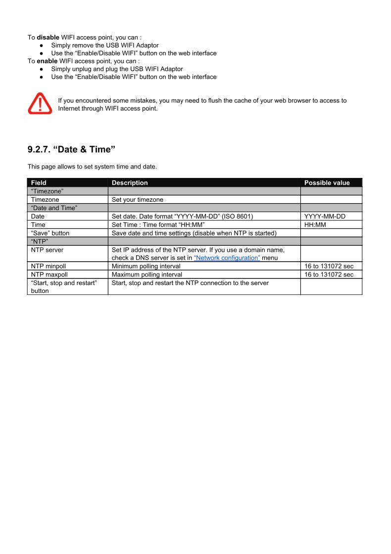
9.2.7. “Date & Time” This page allows to set system time and date.
Field Description Possible value “Timezone” Timezone Set your timezone “Date and Time” Date Set date. Date format “YYYYMMDD” (ISO 8601) YYYYMMDD Time Set Time : Time format “HH:MM” HH:MM “Save” button Save date and time settings (disable when NTP is started) “NTP” NTP server Set IP address of the NTP server. If you use a domain name,
check a DNS server is set in “Network configuration” menu
NTP minpoll Minimum polling interval 16 to 131072 sec NTP maxpoll Maximum polling interval 16 to 131072 sec “Start, stop and restart” button
Start, stop and restart the NTP connection to the server
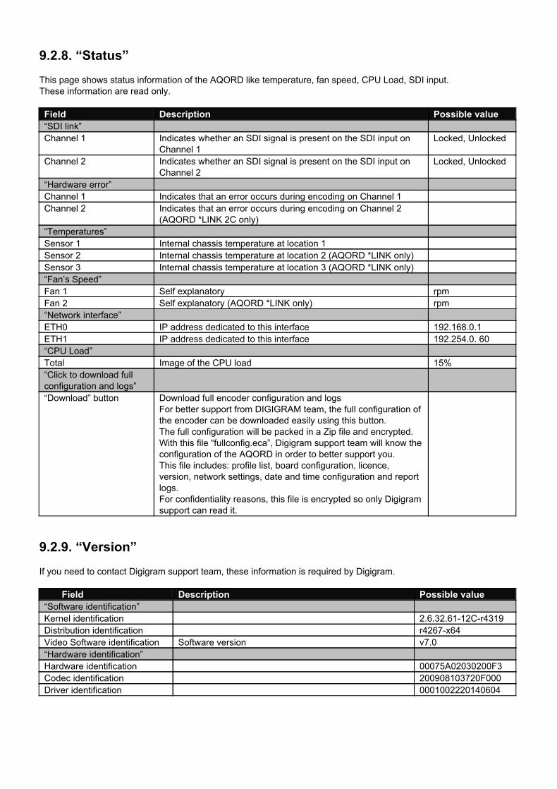
9.2.8. “Status” This page shows status information of the AQORD like temperature, fan speed, CPU Load, SDI input. These information are read only.
Field Description Possible value “SDI link” Channel 1 Indicates whether an SDI signal is present on the SDI input on
Channel 1 Locked, Unlocked
Channel 2 Indicates whether an SDI signal is present on the SDI input on Channel 2
Locked, Unlocked
“Hardware error” Channel 1 Indicates that an error occurs during encoding on Channel 1 Channel 2 Indicates that an error occurs during encoding on Channel 2
(AQORD *LINK 2C only)
“Temperatures” Sensor 1 Internal chassis temperature at location 1 Sensor 2 Internal chassis temperature at location 2 (AQORD *LINK only) Sensor 3 Internal chassis temperature at location 3 (AQORD *LINK only) “Fan’s Speed” Fan 1 Self explanatory rpm Fan 2 Self explanatory (AQORD *LINK only) rpm “Network interface” ETH0 IP address dedicated to this interface 192.168.0.1 ETH1 IP address dedicated to this interface 192.254.0. 60 “CPU Load” Total Image of the CPU load 15% “Click to download full configuration and logs”
“Download” button Download full encoder configuration and logs For better support from DIGIGRAM team, the full configuration of the encoder can be downloaded easily using this button. The full configuration will be packed in a Zip file and encrypted. With this file “fullconfig.eca”, Digigram support team will know the configuration of the AQORD in order to better support you. This file includes: profile list, board configuration, licence, version, network settings, date and time configuration and report logs. For confidentiality reasons, this file is encrypted so only Digigram support can read it.
9.2.9. “Version” If you need to contact Digigram support team, these information is required by Digigram.
Field Description Possible value
“Software identification” Kernel identification 2.6.32.6112Cr4319 Distribution identification r4267x64 Video Software identification Software version v7.0 “Hardware identification” Hardware identification 00075A02030200F3 Codec identification 200908103720F000 Driver identification 0001002220140604
9.2.10. “Update” This page allows the User to update the AQORD software. Digigram support will provide you an update file “xxxx.lbo”.
Follow the instructions below to update the software:
1. Click on “Browse” or “Choisir un fichier” button to browse and select the update file “xxxx.lbo”. 2. Click on “Update” button. 3. The page below displays the update report at the end of the update process. Verify that the status of all of the
steps displayed is “OK”. 4. A restart is required to complete the upgrade. Click on the button "Restart".
9.2.11. “Licence” This page allows to add option to the AQORD like “Forward Error Correction” (FEC) or “Software Encoding” (SWENC: OTT distribution capability). Please, contact Digigram sales representative for more information.
Follow the instructions below to add licence:
1. Click on “Select a file” or “Choisir un fichier” button to browse and select the file provided by Digigram. 2. Click on “Update” button. A reboot is not required.
If you need to add options, Digigram will generate a new licence file specific to your AQORD using the “Platform Id” number.
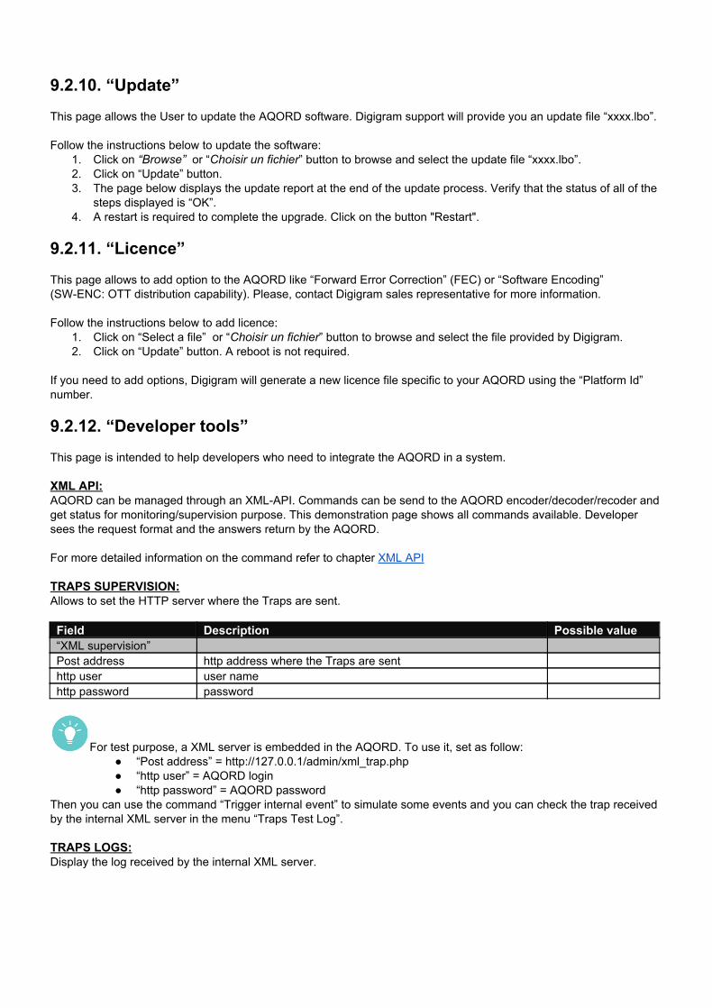
9.2.12. “Developer tools” This page is intended to help developers who need to integrate the AQORD in a system. XML API: AQORD can be managed through an XMLAPI. Commands can be send to the AQORD encoder/decoder/recoder and get status for monitoring/supervision purpose. This demonstration page shows all commands available. Developer sees the request format and the answers return by the AQORD. For more detailed information on the command refer to chapter XML API TRAPS SUPERVISION: Allows to set the HTTP server where the Traps are sent.
Field Description Possible value “XML supervision” Post address http address where the Traps are sent http user user name http password password
For test purpose, a XML server is embedded in the AQORD. To use it, set as follow: “Post address” = http://127.0.0.1/admin/xml_trap.php “http user” = AQORD login “http password” = AQORD password
Then you can use the command “Trigger internal event” to simulate some events and you can check the trap received by the internal XML server in the menu “Traps Test Log”. TRAPS LOGS: Display the log received by the internal XML server.
NETWORK LIMITATIONS: For test purpose and in order to simulate a specific IP link (transcontinental fiber link, satellite link), users can define these parameters for each Ethernet port:
Limit input and output bandwidth Define the percentage of loss packets The packet delay
Don’t forget to set back to “Normal” when tests are finished.
9.3. “Profile” management pages
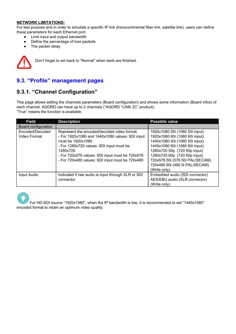
9.3.1. “Channel Configuration” This page allows setting the channels parameters (Board configuration) and shows some information (Board infos) of each channel. AQORD can have up to 2 channels (“AQORD *LINK 2C” product). “True” means the function is available.
Field Description Possible value
Board configuration Encoded/Decoded Video Format
Represent the encoded/decoded video format. For 1920x1080 and 1440x1080 values: SDI input must be 1920x1080 For 1280x720 values: SDI input must be 1280x720 For 720x576 values: SDI input must be 720x576 For 720x480 values: SDI input must be 720x480
1920x1080 50i (1080 50i input) 1920x1080 60i (1080 60i input) 1440x1080 50i (1080 50i input) 1440x1080 60i (1080 60i input) 1280x720 50p (720 50p input) 1280x720 60p (720 60p input) 720x576 50i (576 50i PAL/SECAM) 720x480 60i (480 0i PAL/SECAM) (Write only)
Input Audio Indicated if raw audio is input through XLR or SDI connector.
Embedded audio (SDI connector) AES/EBU audio (XLR connector) (Write only)
For HDSDI source “1920x1080”, when the IP bandwidth is low, it is recommended to set “1440x1080” encoded format to retain an optimum video quality.
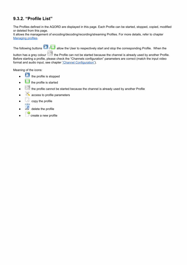
9.3.2. “Profile List” The Profiles defined in the AQORD are displayed in this page. Each Profile can be started, stopped, copied, modified or deleted from this page. It allows the management of encoding/decoding/recording/streaming Profiles. For more details, refer to chapter Managing profiles.
The following buttons / allow the User to respectively start and stop the corresponding Profile. When the
button has a grey colour the Profile can not be started because the channel is already used by another Profile. Before starting a profile, please check the “Channels configuration” parameters are correct (match the input video format and audio input, see chapter “Channel Configuration”).
Meaning of the icons:
the profile is stopped
the profile is started
the profile cannot be started because the channel is already used by another Profile
access to profile parameters
copy the profile
delete the profile
create a new profile
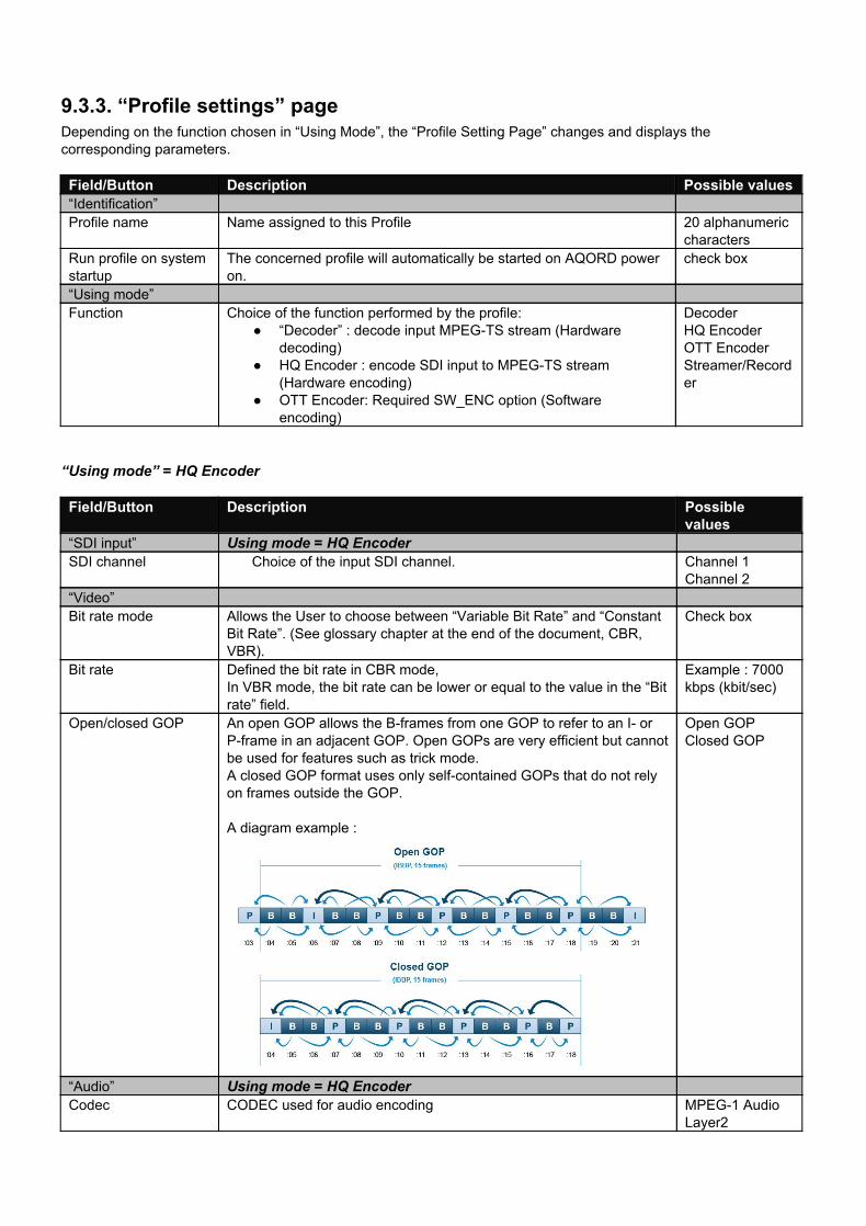
9.3.3. “Profile settings” page Depending on the function chosen in “Using Mode”, the “Profile Setting Page” changes and displays the corresponding parameters.
Field/Button Description Possible values “Identification” Profile name Name assigned to this Profile 20 alphanumeric
characters Run profile on system startup
The concerned profile will automatically be started on AQORD power on.
check box
“Using mode” Function Choice of the function performed by the profile:
“Decoder” : decode input MPEGTS stream (Hardware decoding)
HQ Encoder : encode SDI input to MPEGTS stream (Hardware encoding)
OTT Encoder: Required SW_ENC option (Software encoding)
Decoder HQ Encoder OTT Encoder Streamer/Recorder
“Using mode” = HQ Encoder
Field/Button Description Possible
values “SDI input” Using mode = HQ Encoder SDI channel Choice of the input SDI channel. Channel 1
Channel 2 “Video” Bit rate mode Allows the User to choose between “Variable Bit Rate” and “Constant
Bit Rate”. (See glossary chapter at the end of the document, CBR, VBR).
Check box
Bit rate Defined the bit rate in CBR mode, In VBR mode, the bit rate can be lower or equal to the value in the “Bit rate” field.
Example : 7000 kbps (kbit/sec)
Open/closed GOP An open GOP allows the Bframes from one GOP to refer to an I or Pframe in an adjacent GOP. Open GOPs are very efficient but cannot be used for features such as trick mode. A closed GOP format uses only selfcontained GOPs that do not rely on frames outside the GOP. A diagram example :
Open GOP Closed GOP
“Audio” Using mode = HQ Encoder Codec CODEC used for audio encoding MPEG1 Audio
Layer2
Bit rate Bit rate of the audio stream Example : 128 kbps (kbit/sec)
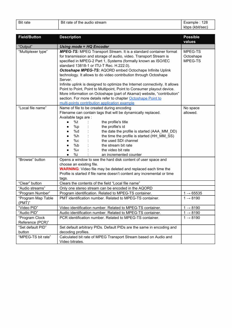
Field/Button Description Possible
values “Output” Using mode = HQ Encoder “Multiplexer type” MPEGTS: MPEG Transport Stream. It is a standard container format
for transmission and storage of audio, video. Transport Stream is specified in MPEG2 Part 1, Systems (formally known as ISO/IEC standard 138181 or ITUT Rec. H.222.0). Octoshape MPEGTS: AQORD embed Octochape Infinite Uplink technology. It allows to do video contribution through Octoshape Server. Infinite uplink is designed to optimize the Internet connectivity. It allows Point to Point, Point to Multipoint, Point to Consumer playout device. More information on Octoshape (part of Akamai) website, “contribution” section. For more details refer to chapter Octoshape Point to multipoints contribution application example
MPEGTS Octoshape MPEGTS
“Local file name” Name of file to be created during encoding Filename can contain tags that will be dynamically replaced. Available tags are :
%t : the profile's title %p : the profile's id %d : the date the profile is started (AAA_MM_DD) %h : the time the profile is started (HH_MM_SS) %c : the used SDI channel %b : the stream bit rate %v : the video bit rate %i : an incremented counter
No space allowed.
“Browse” button Opens a window to see the hard disk content of user space and choose an existing file. WARNING: Video file may be deleted and replaced each time the Profile is started if file name doesn’t content any incremental or time tags.
“Clear” button Clears the contents of the field “Local file name” “Audio streams” Only one stereo stream can be encoded in the AQORD “Program Number” Program identification. Related to MPEGTS container. 1 → 65535 “Program Map Table (PMT)”
PMT identification number. Related to MPEGTS container. 1 → 8190
“Video PID” Video identification number. Related to MPEGTS container. 1 → 8190 “Audio PID” Audio identification number. Related to MPEGTS container. 1 → 8190 “Program Clock Reference (PCR)”
PCR identification number. Related to MPEGTS container. 1 → 8190
“Set default PID” button
Set default arbitrary PIDs. Default PIDs are the same in encoding and decoding profiles.
“MPEGTS bit rate” Calculated bit rate of MPEG Transport Stream based on Audio and Video bitrates.
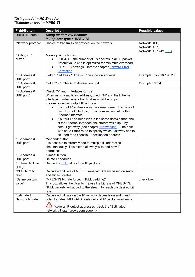
“Using mode” = HQ Encoder “Multiplexer type” = MPEGTS
Field/Button Description Possible values UDP/RTP output Using mode = HQ Encoder
Multiplexer type = MPEGTS
“Network protocol” Choice of transmission protocol on the network. Network UDP, Network RTP, Network RTP with FEC
“Settings…” button
Allows you to choose: UDP/RTP: the number of TS packets in an IP packet.
Default value of 7 is optimized for minimum overhead. RTP: FEC settings. Refer to chapter Forward Error
Correction
“IP Address & UDP port”
Field “IP address “: This is IP destination address Example : 172.16.176.20
“IP Address & UDP port”
Field “Port”: This is IP destination port Example : 5004
“IP Address & UDP port”
Check “M” and “Interfaces 0, 1, 2” When using a multicast address, check "M" and the Ethernet interface number where the IP stream will be output. In case of unicast output IP address :
If output IP address is in the same domain than one of the Ethernet interface, the stream will output by this Ethernet interface.
If output IP address isn’t in the same domain than one of the Ethernet interface, the stream will output by default gateway (see chapter “Networking”). The best is to set a Static route to specify which Gateway has to be used for a specific IP destination address.
“IP Address & UDP port”
“Append” button It is possible to stream video to multiple IP addresses simultaneously. This button allows you to add new IP addresses.
“IP Address & UDP port”
“Cross” button Delete IP address.
“IP Time To Live (TTL)”
Define the TTL value of the IP packets.
“MPEGTS bit rate”
Calculated bit rate of MPEG Transport Stream based on Audio and Video bitrates.
“Define custom value”
“MPEGTS bit rate forced (NULL padding)” This box allows the User to impose the bit rate of MPEGTS. NULL packets will added to the stream to reach the desired bit rate.
check box
“Estimated Network bit rate”
Calculated bit rate on the IP network depends on audio and video bit rates, MPEGTS container and IP packet overheads.
If several IP output addresses is set, the “Estimated network bit rate” grows consequently.
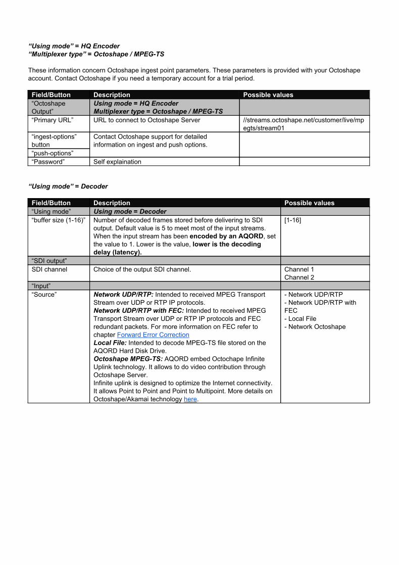
“Using mode” = HQ Encoder “Multiplexer type” = Octoshape / MPEGTS
These information concern Octoshape ingest point parameters. These parameters is provided with your Octoshape account. Contact Octoshape if you need a temporary account for a trial period.
Field/Button Description Possible values “Octoshape Output”
Using mode = HQ Encoder Multiplexer type = Octoshape / MPEGTS
“Primary URL” URL to connect to Octoshape Server //streams.octoshape.net/customer/live/mpegts/stream01
“ingestoptions” button
Contact Octoshape support for detailed information on ingest and push options.
“pushoptions” “Password” Self explaination “Using mode” = Decoder
Field/Button Description Possible values “Using mode” Using mode = Decoder “buffer size (116)” Number of decoded frames stored before delivering to SDI
output. Default value is 5 to meet most of the input streams. When the input stream has been encoded by an AQORD, set the value to 1. Lower is the value, lower is the decoding delay (latency).
[116]
“SDI output” SDI channel Choice of the output SDI channel. Channel 1
Channel 2 “Input” “Source” Network UDP/RTP: Intended to received MPEG Transport
Stream over UDP or RTP IP protocols. Network UDP/RTP with FEC: Intended to received MPEG Transport Stream over UDP or RTP IP protocols and FEC redundant packets. For more information on FEC refer to chapter Forward Error Correction Local File: Intended to decode MPEGTS file stored on the AQORD Hard Disk Drive. Octoshape MPEGTS: AQORD embed Octochape Infinite Uplink technology. It allows to do video contribution through Octoshape Server. Infinite uplink is designed to optimize the Internet connectivity. It allows Point to Point and Point to Multipoint. More details on Octoshape/Akamai technology here.
Network UDP/RTP Network UDP/RTP with FEC Local File Network Octoshape
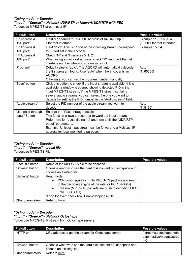
“Using mode” = Decoder “Input” ”Source” = Network UDP/RTP or Network UDP/RTP with FEC To decode MPEGTS stream over IP
Field/Button Description Possible values “IP Address & UDP port”
Field “IP address “: This is IP address of AQORD input Ethernet interface.
Example : 192.168.0.4 (ETH0 Ethernet Interface)
“IP Address & UDP port”
Field “Port”: This is IP port of the incoming stream (correspond to IP port set in the encoder).
Example : 5004
“IP Address & UDP port”
Check “M” and “Interfaces 0, 1, 2” When using a multicast address, check "M" and the Ethernet interface number where to stream will input.
“Program” Default value is “auto”. The AQORD will automatically decode the first program found. Use “auto” when the encoder is an AQORD. Otherwise, you can set the program number manually.
Auto [1..65535]
“Scan” button Click this button to check if the input stream is available. If it is available, a window is opened showing detected PID in the input MPEGTS stream. If the MPEGTS stream contains several audio streams, you can select the one you want to decode by setting the PID number in the “Audio stream” field.
“Audio streams” Select the PID number of the audio stream you want to decode.
Auto [1..8190]
“Use passthrough ouput” Button
Enlarge the “Passthrough” section. This function allows to record or forward the input stream. Refer here for “Local file name” and here to fill the “UDP/RTP ouput” parameters. Example: Unicast input stream can be forward to a Multicast IP address for local monitoring purpose.
“Using mode” = Decoder “Input” ”Source” = Local file To decode MPEGTS File Field/Button Description Possible values “Local file name” Name of the MPEGTS file to be decoded. “Browse” button Opens a window to see the hard disk content of user space and
choose an existing file.
“Settings” button Read mode : PCR Loop regulation (File MPEGTS packets are send
to the decoding engine at the rate for PCR packets) Free run (MPEGTS packets are push to decoding FIFO
until FIFO is full) “Loop for ever” check box: Enable looping in file
Other parameters Refer to here
“Using mode” = Decoder “Input” ”Source” = Network Octoshape To decode MPEGTS IP stream from Octoshape servers
Field/Button Description Possible values “HTTP url” URL address to get the stream for Octoshape server. //streams.octoshape.net/c
ustomer/live/mpegts/stream01
“Browse” button Opens a window to see the hard disk content of user space and choose an existing file.
Other parameters Refer to here
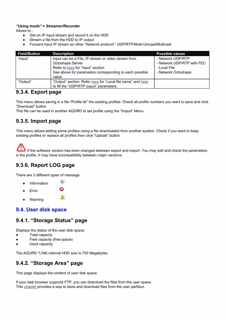
“Using mode” = Streamer/Recorder Allows to :
Get an IP input stream and record it on the HDD Stream a file from the HDD to IP output Forward input IP stream an other “Network protocol”: UDP/RTP/MultiUnicast/Multicast
Field/Button Description Possible values “Input” Input can be a File, IP stream or video stream from
Octoshape Server. Refer to here for “Input” section See above for parameters corresponding to each possible value.
Network UDP/RTP Network UDP/RTP with FEC Local File Network Octoshape
“Output” “Output” section: Refer here for “Local file name” and here to fill the “UDP/RTP ouput” parameters.
9.3.4. Export page This menu allows saving in a file “Profile.lst” the existing profiles. Check all profile numbers you want to save and click “Download” button. This file can be used in another AQORD to set profile using the “Import” Menu.
9.3.5. Import page This menu allows adding some profiles using a file downloaded from another system. Check if you want to keep existing profiles or replace all profiles then click “Upload” button.
If the software version has been changed between export and import. You may edit and check the parameters in the profile. It may have incompatibility between major versions.
9.3.6. Report LOG page There are 3 different types of message:
Information
Error
Warning
9.4. User disk space
9.4.1. “Storage Status” page Displays the status of the user disk space: Total capacity Free capacity (free space) Used capacity The AQORD *LINK internal HDD size is 750 Megabytes
9.4.2. “Storage Area” page This page displays the content of user disk space. If your web browser supports FTP, you can download the files from the user space. This chapter provides a way to store and download files from the user partition.
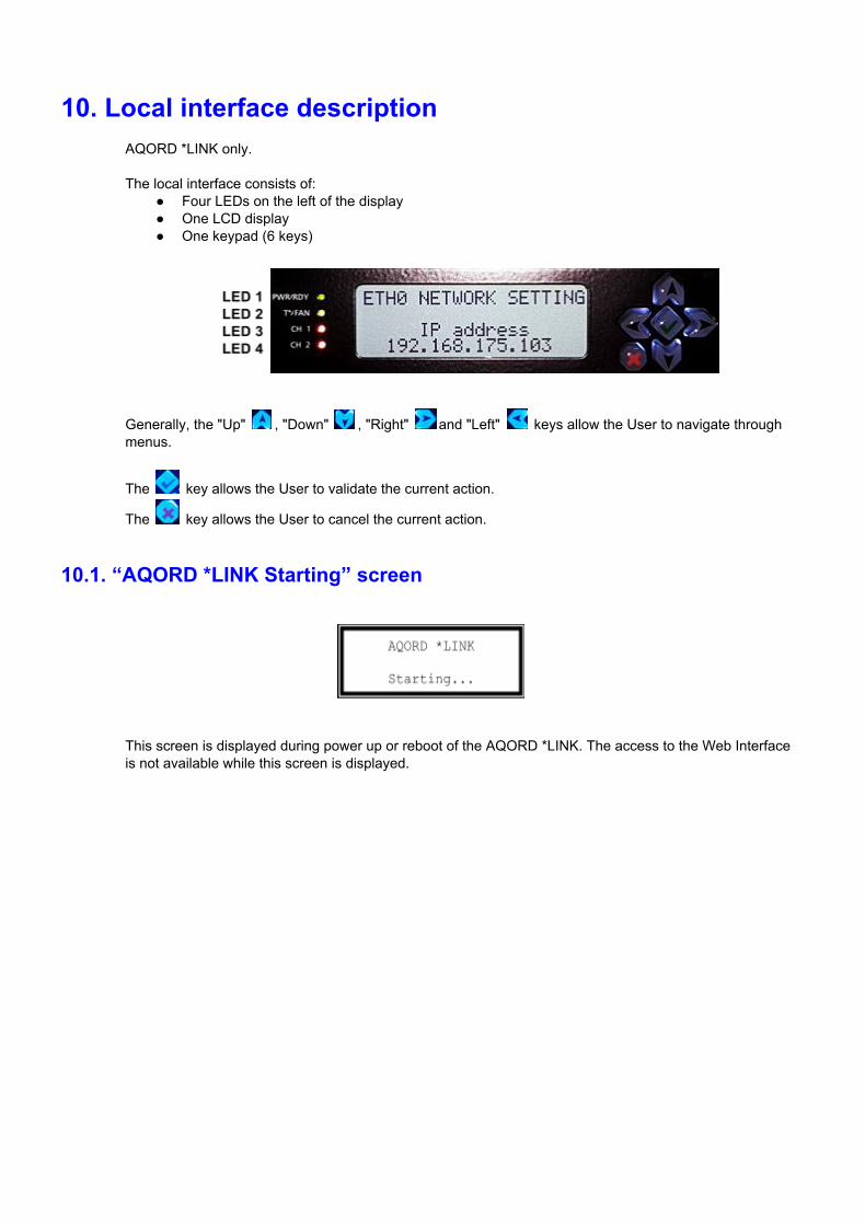
10. Local interface description AQORD *LINK only. The local interface consists of:
Four LEDs on the left of the display One LCD display One keypad (6 keys)
Generally, the "Up" , "Down" , "Right" and "Left" keys allow the User to navigate through menus.
The key allows the User to validate the current action.
The key allows the User to cancel the current action.
10.1. “AQORD *LINK Starting” screen
This screen is displayed during power up or reboot of the AQORD *LINK. The access to the Web Interface is not available while this screen is displayed.
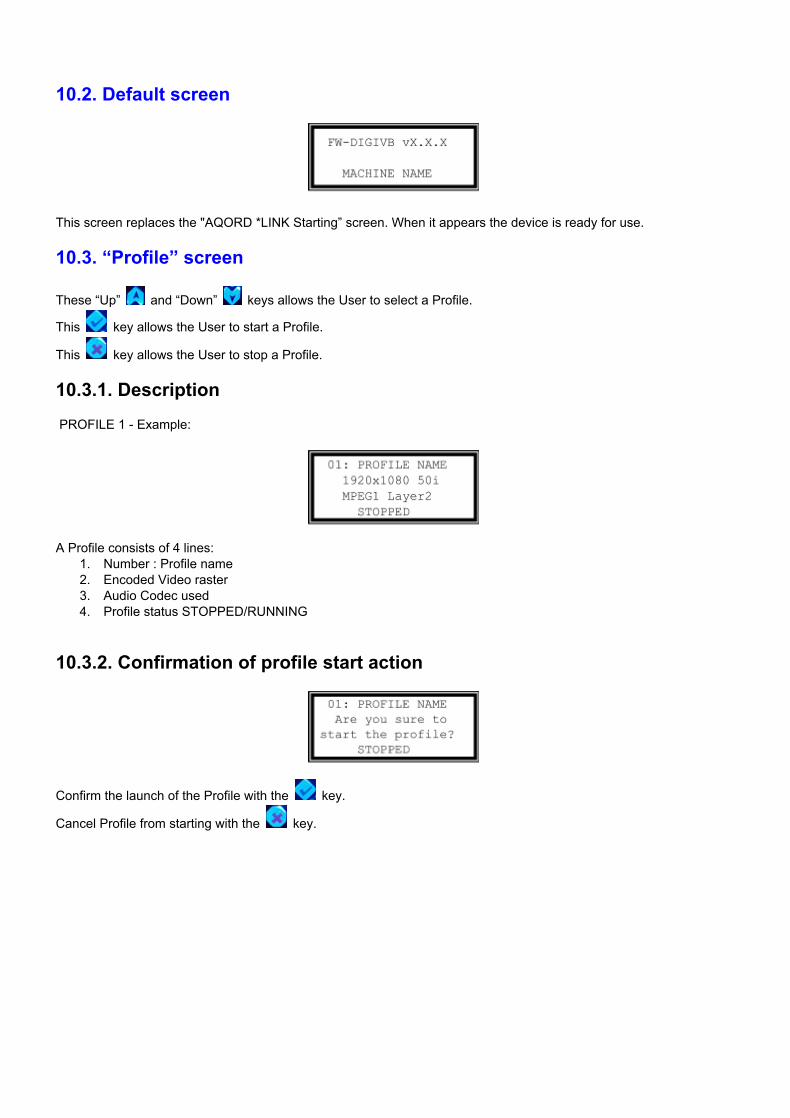
10.2. Default screen
This screen replaces the "AQORD *LINK Starting” screen. When it appears the device is ready for use.
10.3. “Profile” screen
These “Up” and “Down” keys allows the User to select a Profile.
This key allows the User to start a Profile.
This key allows the User to stop a Profile.
10.3.1. Description PROFILE 1 Example:
A Profile consists of 4 lines:
1. Number : Profile name 2. Encoded Video raster 3. Audio Codec used 4. Profile status STOPPED/RUNNING
10.3.2. Confirmation of profile start action
Confirm the launch of the Profile with the key.
Cancel Profile from starting with the key.
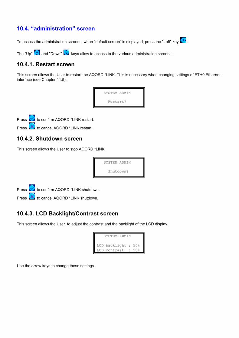
10.4. “administration” screen
To access the administration screens, when “default screen” is displayed, press the "Left" key .
The "Up” and "Down" keys allow to access to the various administration screens.
10.4.1. Restart screen This screen allows the User to restart the AQORD *LINK. This is necessary when changing settings of ETH0 Ethernet interface (see Chapter 11.5).
Press to confirm AQORD *LINK restart.
Press to cancel AQORD *LINK restart.
10.4.2. Shutdown screen This screen allows the User to stop AQORD *LINK
Press to confirm AQORD *LINK shutdown.
Press to cancel AQORD *LINK shutdown.
10.4.3. LCD Backlight/Contrast screen This screen allows the User to adjust the contrast and the backlight of the LCD display.
Use the arrow keys to change these settings.
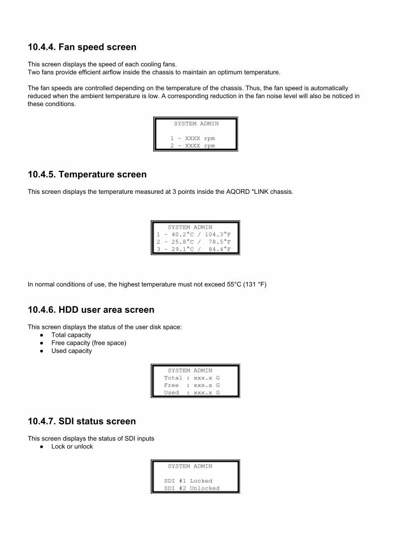
10.4.4. Fan speed screen This screen displays the speed of each cooling fans. Two fans provide efficient airflow inside the chassis to maintain an optimum temperature. The fan speeds are controlled depending on the temperature of the chassis. Thus, the fan speed is automatically reduced when the ambient temperature is low. A corresponding reduction in the fan noise level will also be noticed in these conditions.
10.4.5. Temperature screen This screen displays the temperature measured at 3 points inside the AQORD *LINK chassis.
In normal conditions of use, the highest temperature must not exceed 55°C (131 °F)
10.4.6. HDD user area screen This screen displays the status of the user disk space:
Total capacity Free capacity (free space) Used capacity
10.4.7. SDI status screen This screen displays the status of SDI inputs
Lock or unlock
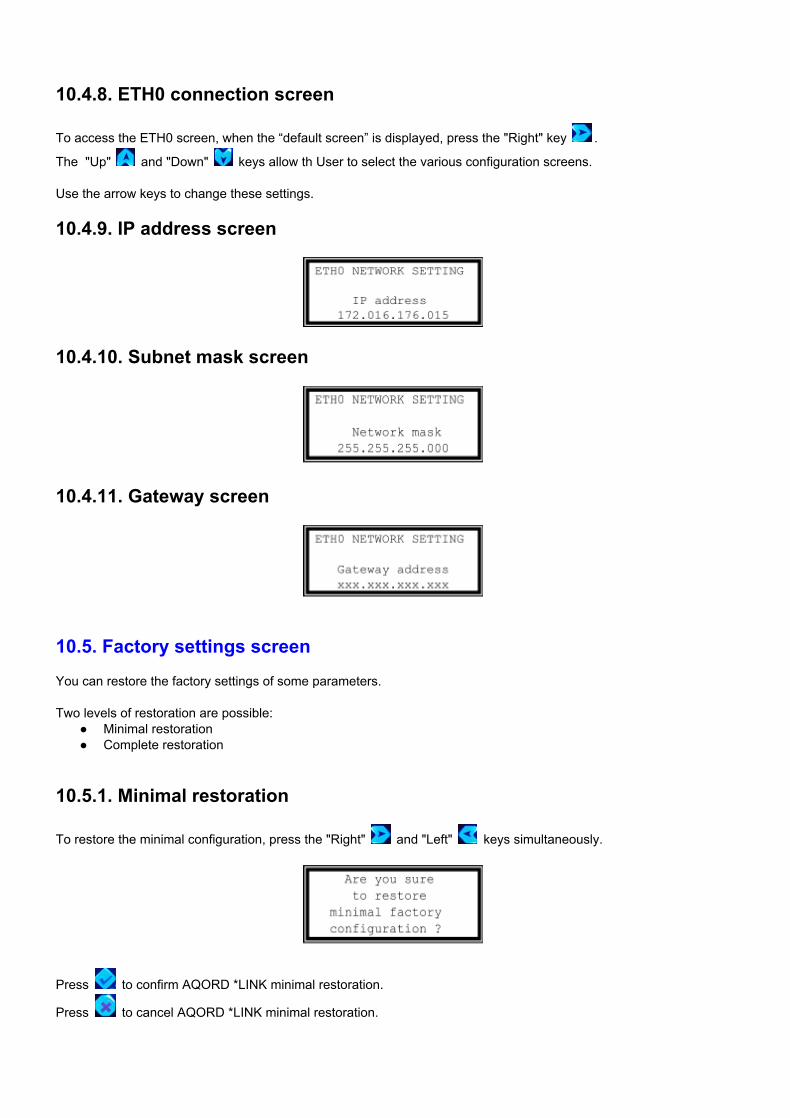
10.4.8. ETH0 connection screen
To access the ETH0 screen, when the “default screen” is displayed, press the "Right" key .
The "Up" and "Down" keys allow th User to select the various configuration screens. Use the arrow keys to change these settings.
10.4.9. IP address screen
10.4.10. Subnet mask screen
10.4.11. Gateway screen
10.5. Factory settings screen You can restore the factory settings of some parameters. Two levels of restoration are possible:
Minimal restoration Complete restoration
10.5.1. Minimal restoration
To restore the minimal configuration, press the "Right" and "Left" keys simultaneously.
Press to confirm AQORD *LINK minimal restoration.
Press to cancel AQORD *LINK minimal restoration.
List of initialized parameters:
ETH0 parameters IP address : 192.168.0.1 Submask : 255.255.0.0 Gateway : 0.0.0.0
Login and password Login : admin Password : digigram38
AQORD *LINK name Contrast and backlight level at 50%
10.5.2. Complete restoration
To restore the complete configuration, press the "Up" and "Down" keys simultaneously.
Press to confirm AQORD *LINK complete restoration.
Press to cancel AQORD *LINK complete restoration. List of initialized parameters:
Same as minimal restoration Reset Profile list
10.6. Definition of LED status This chapter describes the meaning of the four LEDs on front panel (on the left of the LCD display). The description of LEDs is from top to bottom (their positions are specified chapter 11).
LED 1 AQORD *LINK status Green = the AQORD *LINK is ready Orange = the AQORD *LINK is main supplied but not started or it is being started.
LED 2 Error LED Green = no error Red = temperature error (at least one sensor is reporting a temperature higher than 55°C) or a fan
malfunction (at least one fan has a fan speed below 2000 rpm) LED 3 Encoding Channel 1 status
Orange = Idle Red = Channel error (mismatch between the encoded format set in “Board Configuration” and video
format input in SDI) Green = Encoding are pending
LED 4 Encoding Channel 2 status Orange = Idle Red = Channel error (mismatch between the encoded format set in “Board Configuration” and video
format input in SDI) Green = Encoding are pending
11. Managing profiles The Profile management is done through the Web interface. To access the Web interface of the AQORD, follow the instructions here.
11.1. Define a new profile To create a new Profile, follow the instructions below:
1. In "Profile Administration" page click the “New Profile” icon. 2. Choose the parameters that define the Profile. See this chapter for more details. 3. Click “Save Profile” button to save this new Profile.
The Profile now appears on the "Profile Management" page.
11.2. Modify profile parameters To modify a Profile, follow the instructions below:
1. In the "Profile Administration" page click the parameter icon corresponding to the Profile to be modified. 2. The Profile parameters are now accessible and can be modified. See this chapter for more details. 3. Click the “Save Profile” button to save this new Profile.
11.3. Duplicate a Profile It may be convenient to create a Profile from an existing Profile when few parameters vary. To duplicate a Profile follow the instructions below:
1. In "Profile Administration" page click the duplicate icon corresponding to the Profile to be duplicated.
A new Profile is created at the bottom of the Profile list with the same name of the copied Profile preceded by "Copy". To modify the duplicated Profile, follow the instructions here.
11.4. Delete a profile To delete a Profile, follow the instructions below:
1. In the "Profile Administration" page click the delete icon corresponding to the Profile to be deleted. 2. Confirm the deleting in the popup window.
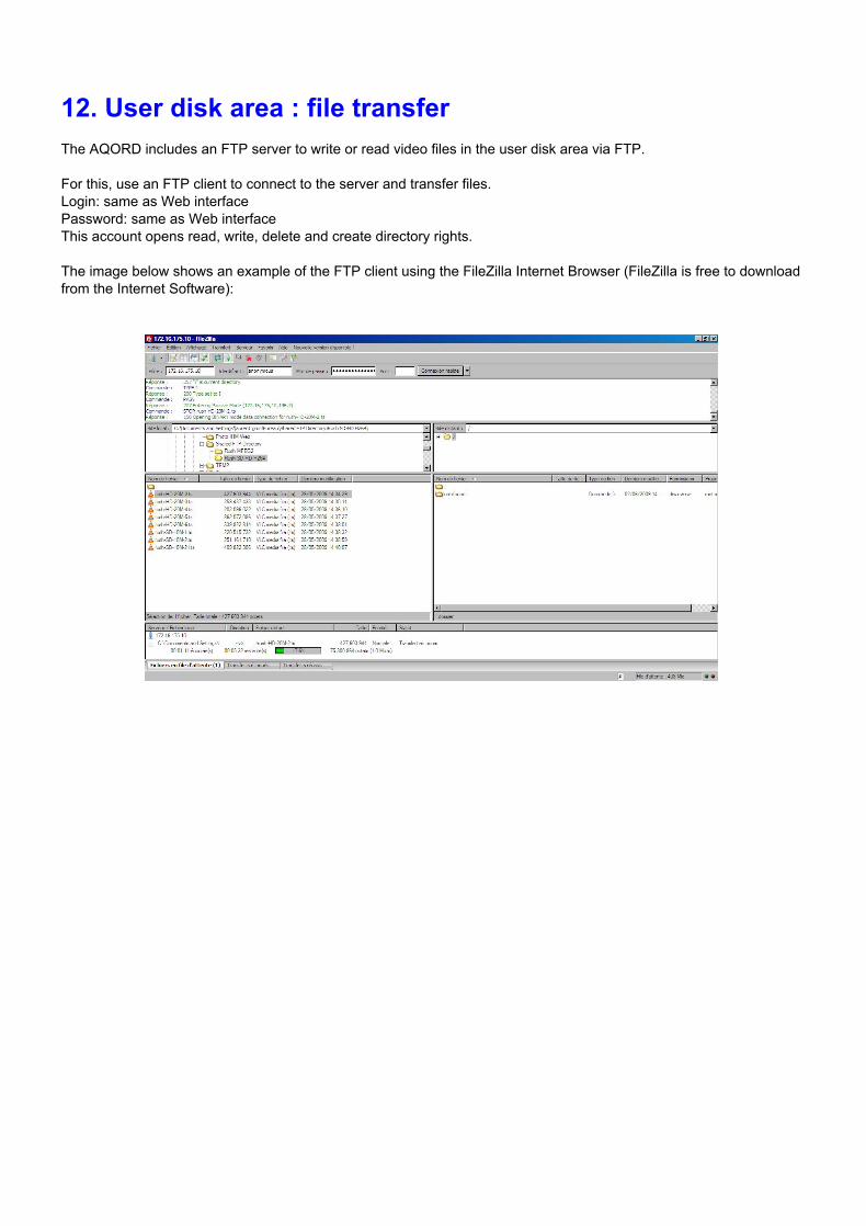
12. User disk area : file transfer The AQORD includes an FTP server to write or read video files in the user disk area via FTP. For this, use an FTP client to connect to the server and transfer files. Login: same as Web interface Password: same as Web interface This account opens read, write, delete and create directory rights. The image below shows an example of the FTP client using the FileZilla Internet Browser (FileZilla is free to download from the Internet Software):
13. Software update See this chapter.
14. Forward Error Correction 14.1. Introduction Unfortunately, real networks are not perfect and packet losses occur. In order to cope with packet losses, the AQORD has implemented ProMPEG FEC according to ProMPEG Code of Practice #3 rev. 2. ProMPEG FEC is carried out on RTP packets. The mechanism is based on the insertion of additional data containing the result of an XOR (exclusive OR)operation of packets over a time window. The generation of FEC packets is based on the use of a matrix. The matrix size is defined by the number of columns (L) and the number of rows (D). By iterative operations it is possible to correct more than one missing packet per column or row. Please note that 4 ≤ L ≤ 32, 4 ≤ D ≤ 32 and L+D ≤ 32 and that the maximum matrix size is 256(L*D). When using column FEC only, L is allowed to be in the range 1 ≤ L ≤ 32. The size of the matrix is a trade between latency, transmission overhead and error protection. Column FEC provides correction for consecutive burst packets loss of up to L packets. The FEC packets are generated per a column within the matrix allowing loss of any single media packet within a column or a burst of packets of errors within a row to be corrected through the FEC packet.Column FEC is used to correct burst errors and random errors.
Row FEC provides correction of nonconsecutive packet loss and can correct any single packet loss within a row of media packets. The FEC packets are generated per a row allowing loss of any single packet to be recovered. Row FEC is ideal for correcting random packet errors. Once the FEC packets have been computed they are transmitted with the media packets to the receiver site. FEC column packets are transmitted on UDP port n+2 and FEC row packets are transmitted on UDP port n+4 where n is the UDP port of the media data. This is in accordance with ProMPEG CoP 3.
14.2. How to monitor packets lost and packets recovered To monitor packets lost, packets recovered and more, refer to chapter “Usage statistics”
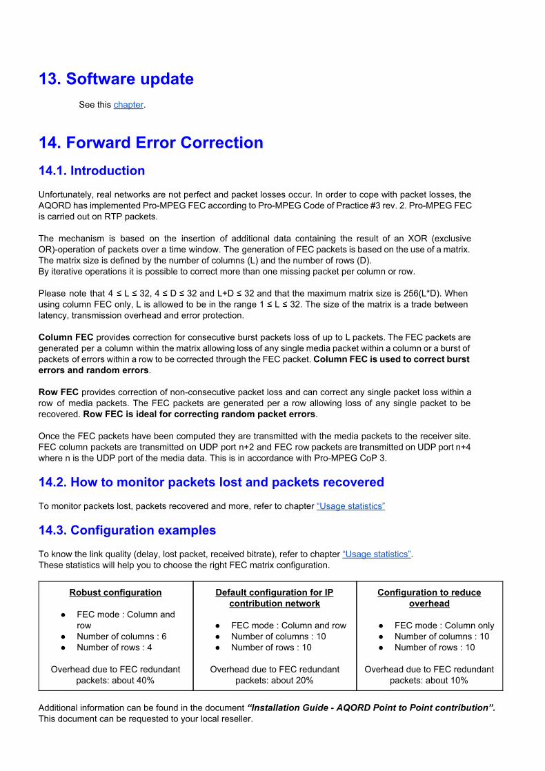
14.3. Configuration examples To know the link quality (delay, lost packet, received bitrate), refer to chapter “Usage statistics”. These statistics will help you to choose the right FEC matrix configuration.
Robust configuration
FEC mode : Column and row
Number of columns : 6 Number of rows : 4
Overhead due to FEC redundant
packets: about 40%
Default configuration for IP contribution network
FEC mode : Column and row Number of columns : 10 Number of rows : 10
Overhead due to FEC redundant
packets: about 20%
Configuration to reduce overhead
FEC mode : Column only Number of columns : 10 Number of rows : 10
Overhead due to FEC redundant
packets: about 10%
Additional information can be found in the document “Installation Guide AQORD Point to Point contribution”. This document can be requested to your local reseller.
15. XML API XML API allows to control the unit from another application or external equipment for monitoring and control purpose. A web interface is dedicated to developers who need to use the XMLAPI. More information is available at this chapter.
15.1. General presentation The Digigram video products provide a XML API that allows the following actions:
start_profile: Start a profile. stop_profile: Stop a profile get_profile_list: Return the profile list export profiles: Export the profiles into an xml document import profiles: Import the profiles from an xml document get file list: Get the file names in the HDD user area delete file: Deletes the specified file clear output: Removes the output files that are created by the specified profile get_hardware_status: Return the hardware status of the unit (temp, Fan speed, IP address, Storage) set_ip: Allow IP configuration. restart: Restart the unit shutdown: Shutdown the unit get a system value: Gets a value or value set through a simple request (RAM memory status, fan speed) Trigger internal event: Generates event messages (for simulation), that can be sent as an XML trap,
displayed on web interface or simply logged in the “Report log”.
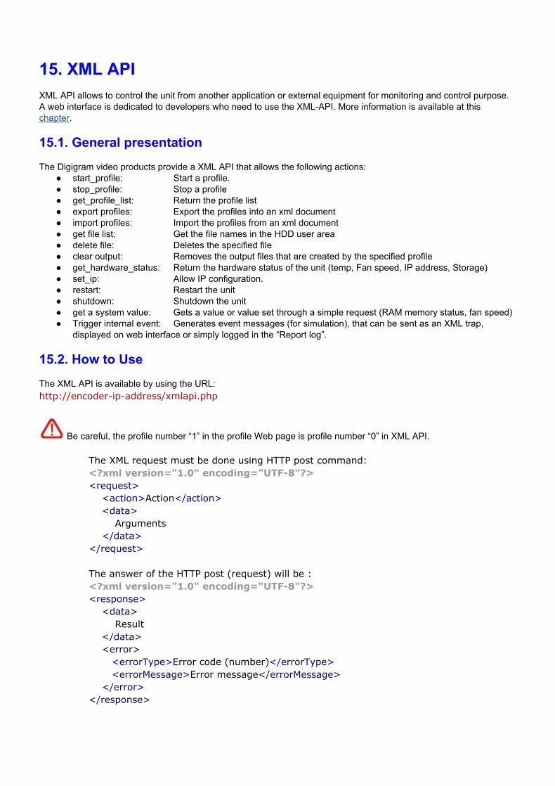
15.2. How to Use The XML API is available by using the URL: http://encoderipaddress/xmlapi.php
Be careful, the profile number “1” in the profile Web page is profile number “0” in XML API.
The XML request must be done using HTTP post command: <?xml version="1.0" encoding="UTF8"?> <request> <action>Action</action> <data> Arguments </data> </request> The answer of the HTTP post (request) will be : <?xml version="1.0" encoding="UTF8"?> <response> <data> Result </data> <error> <errorType>Error code (number)</errorType> <errorMessage>Error message</errorMessage> </error> </response>
15.3. Commands example
Below are some command examples. See above for the full command list.
15.3.1. “start_profile” This action allows to start a profile. XML Request:
<?xml version="1.0" encoding="UTF8"?> <request> <action>start_profile</action> <data> Profile index to start </data> </request>
XML answer if no error: <?xml version="1.0" encoding="UTF8"?> <response> <data> ok </data> </response>
XML answer if the profile does not exist (bad profile index): <?xml version="1.0" encoding="UTF8"?> <response> <data> ko </data> <error> <errorType>2</errorType> <errorMessage>the profile index does not exist</errorMessage> </error> </response>
XML answer if other errors: <?xml version="1.0" encoding="UTF8"?> <response> <data> ko </data> <error> <errorType>100</errorType> <errorMessage>Error message explaining the problem</errorMessage> </error> </response>
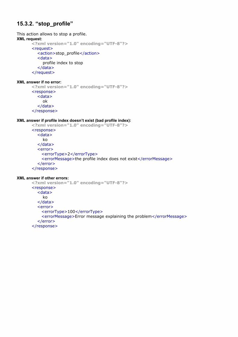
15.3.2. “stop_profile” This action allows to stop a profile. XML request:
<?xml version="1.0" encoding="UTF8"?> <request> <action>stop_profile</action> <data> profile index to stop </data> </request>
XML answer if no error: <?xml version="1.0" encoding="UTF8"?> <response> <data> ok </data> </response>
XML answer if profile index doesn’t exist (bad profile index): <?xml version="1.0" encoding="UTF8"?> <response> <data> ko </data> <error> <errorType>2</errorType> <errorMessage>the profile index does not exist</errorMessage> </error> </response>
XML answer if other errors: <?xml version="1.0" encoding="UTF8"?> <response> <data> ko </data> <error> <errorType>100</errorType> <errorMessage>Error message explaining the problem</errorMessage> </error> </response>
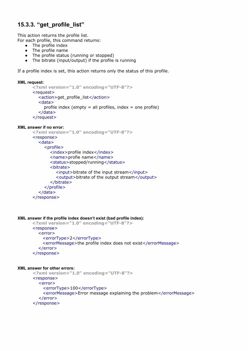
15.3.3. “get_profile_list” This action returns the profile list. For each profile, this command returns:
The profile index The profile name The profile status (running or stopped) The bitrate (input/output) if the profile is running
If a profile index is set, this action returns only the status of this profile. XML request:
<?xml version="1.0" encoding="UTF8"?> <request> <action>get_profile_list</action> <data> profile index (empty = all profiles, index = one profile) </data> </request>
XML answer if no error: <?xml version="1.0" encoding="UTF8"?> <response> <data> <profile> <index>profile index</index> <name>profie name</name> <status>stopped/running</status> <bitrate> <input>bitrate of the input stream</input> <output>bitrate of the output stream</output> </bitrate> </profile> </data> </response>
XML answer if the profile index doesn’t exist (bad profile index):
<?xml version="1.0" encoding="UTF8"?> <response> <error> <errorType>2</errorType> <errorMessage>the profile index does not exist</errorMessage> </error> </response>
XML answer for other errors:
<?xml version="1.0" encoding="UTF8"?> <response> <error> <errorType>100</errorType> <errorMessage>Error message explaining the problem</errorMessage> </error> </response>
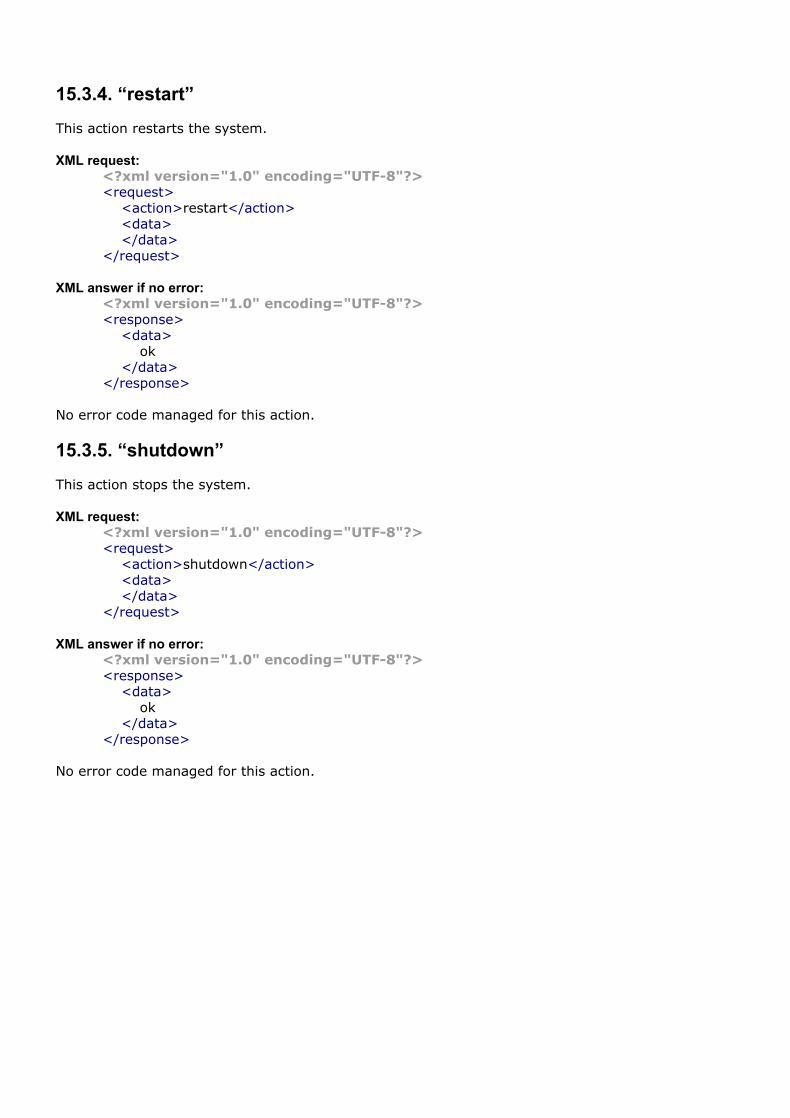
15.3.4. “restart” This action restarts the system. XML request:
<?xml version="1.0" encoding="UTF8"?> <request> <action>restart</action> <data> </data> </request>
XML answer if no error: <?xml version="1.0" encoding="UTF8"?> <response> <data> ok </data> </response>
No error code managed for this action.
15.3.5. “shutdown” This action stops the system. XML request:
<?xml version="1.0" encoding="UTF8"?> <request> <action>shutdown</action> <data> </data> </request>
XML answer if no error: <?xml version="1.0" encoding="UTF8"?> <response> <data> ok </data> </response>
No error code managed for this action.
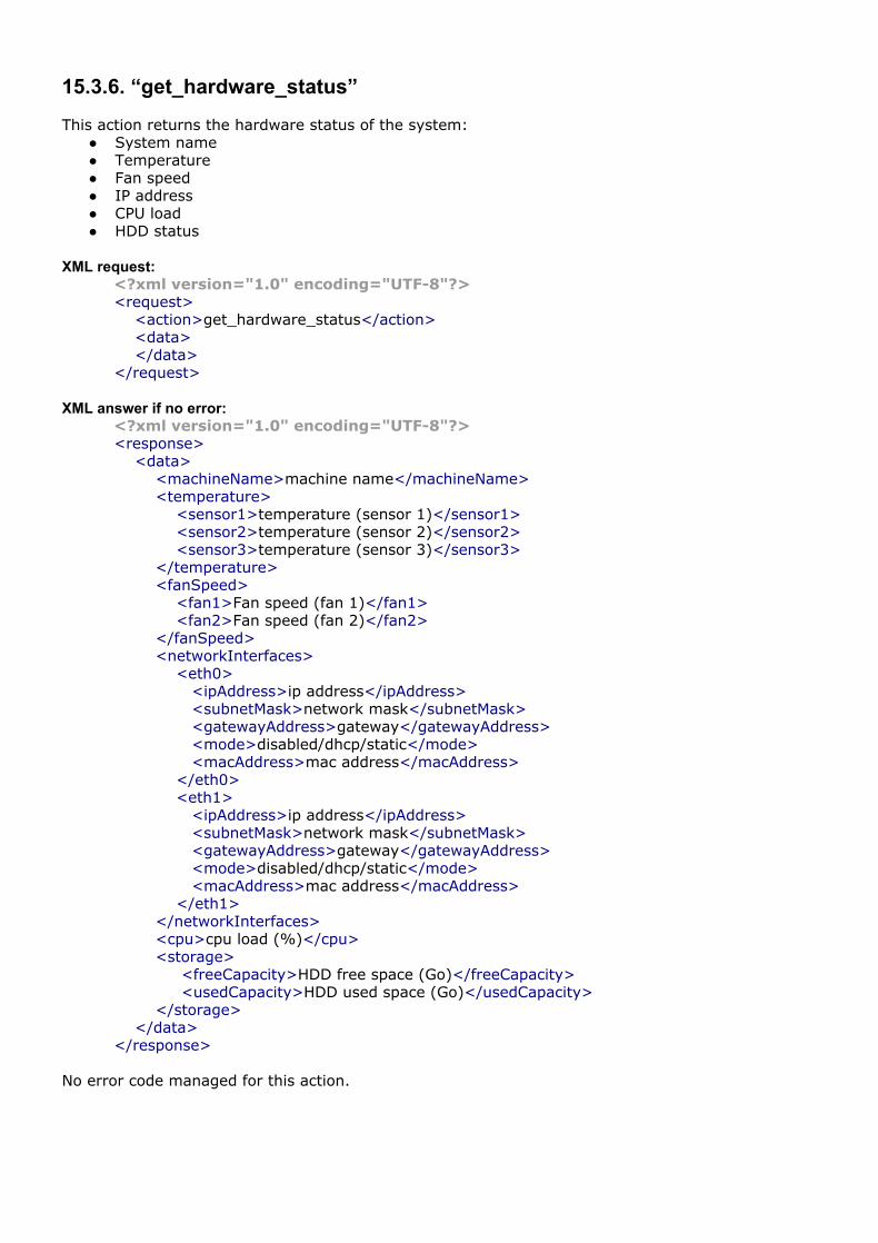
15.3.6. “get_hardware_status” This action returns the hardware status of the system:
System name Temperature Fan speed IP address CPU load HDD status
XML request:
<?xml version="1.0" encoding="UTF8"?> <request> <action>get_hardware_status</action> <data> </data> </request>
XML answer if no error: <?xml version="1.0" encoding="UTF8"?> <response> <data> <machineName>machine name</machineName> <temperature> <sensor1>temperature (sensor 1)</sensor1> <sensor2>temperature (sensor 2)</sensor2> <sensor3>temperature (sensor 3)</sensor3> </temperature> <fanSpeed> <fan1>Fan speed (fan 1)</fan1> <fan2>Fan speed (fan 2)</fan2> </fanSpeed> <networkInterfaces> <eth0> <ipAddress>ip address</ipAddress> <subnetMask>network mask</subnetMask> <gatewayAddress>gateway</gatewayAddress> <mode>disabled/dhcp/static</mode> <macAddress>mac address</macAddress> </eth0> <eth1> <ipAddress>ip address</ipAddress> <subnetMask>network mask</subnetMask> <gatewayAddress>gateway</gatewayAddress> <mode>disabled/dhcp/static</mode> <macAddress>mac address</macAddress> </eth1> </networkInterfaces> <cpu>cpu load (%)</cpu> <storage> <freeCapacity>HDD free space (Go)</freeCapacity> <usedCapacity>HDD used space (Go)</usedCapacity> </storage> </data> </response>
No error code managed for this action.
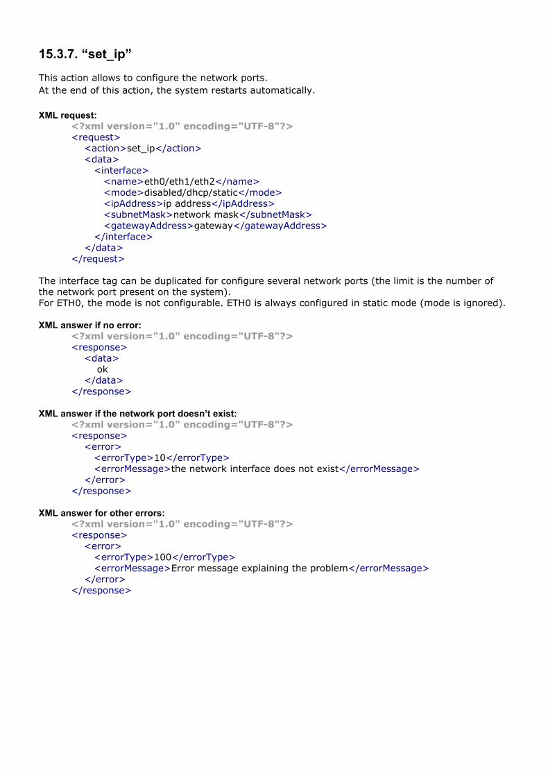
15.3.7. “set_ip” This action allows to configure the network ports. At the end of this action, the system restarts automatically. XML request:
<?xml version="1.0" encoding="UTF8"?> <request> <action>set_ip</action> <data> <interface> <name>eth0/eth1/eth2</name> <mode>disabled/dhcp/static</mode> <ipAddress>ip address</ipAddress> <subnetMask>network mask</subnetMask> <gatewayAddress>gateway</gatewayAddress> </interface> </data> </request>
The interface tag can be duplicated for configure several network ports (the limit is the number of the network port present on the system). For ETH0, the mode is not configurable. ETH0 is always configured in static mode (mode is ignored).
XML answer if no error:
<?xml version="1.0" encoding="UTF8"?> <response> <data> ok </data> </response>
XML answer if the network port doesn’t exist: <?xml version="1.0" encoding="UTF8"?> <response> <error> <errorType>10</errorType> <errorMessage>the network interface does not exist</errorMessage> </error> </response>
XML answer for other errors: <?xml version="1.0" encoding="UTF8"?> <response> <error> <errorType>100</errorType> <errorMessage>Error message explaining the problem</errorMessage> </error> </response>
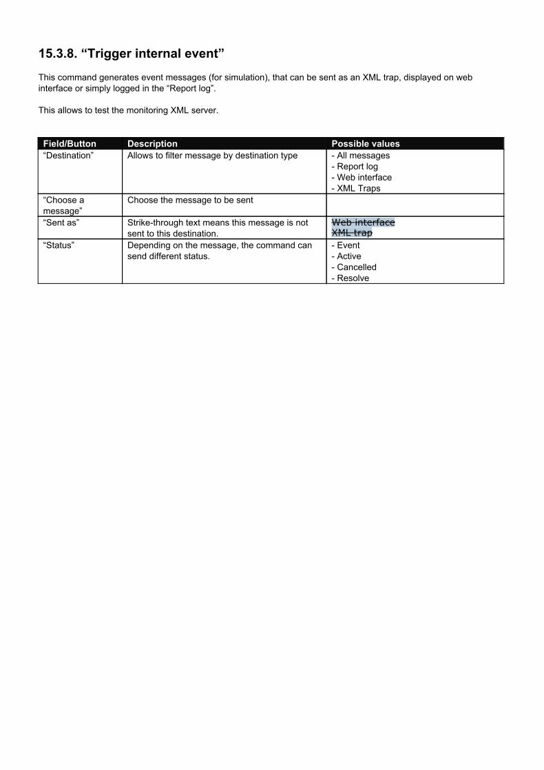
15.3.8. “Trigger internal event” This command generates event messages (for simulation), that can be sent as an XML trap, displayed on web interface or simply logged in the “Report log”. This allows to test the monitoring XML server.
Field/Button Description Possible values “Destination” Allows to filter message by destination type All messages
Report log Web interface XML Traps
“Choose a message”
Choose the message to be sent
“Sent as” Strikethrough text means this message is not sent to this destination.
Web interface XML trap
“Status” Depending on the message, the command can send different status.
Event Active Cancelled Resolve
16. Typical applications The AQORD can address different markets like Broadcast and IPTV. This section presents some typical applications for these markets like:
Full Duplex video transfert for conferencing, training, meeting for corporate or academic applications. Point to point contribution to transmit high video quality over long distances through IP network. Live Event Contribution to Studio for video processing. Contribution using Octoshape Infinite HD technology. IPTV video distribution on Local Area Network for SetTopBox or computer player.
For more information on how to configure AQORD for point to point application, request to Digigram support the guideline document : “Point to Point Contribution Application Installation guide“
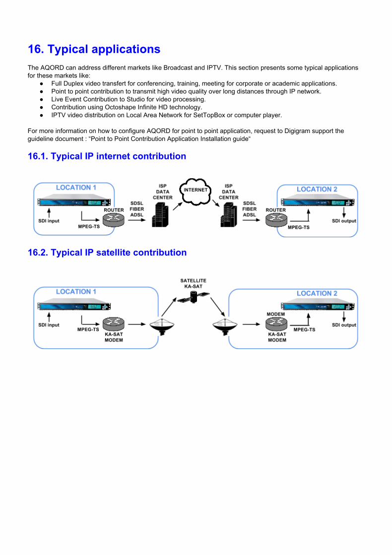
16.1. Typical IP internet contribution
16.2. Typical IP satellite contribution
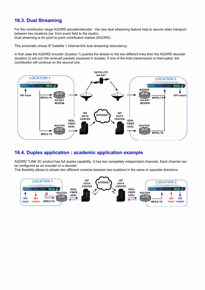
16.3. Dual Streaming For the contribution range AQORD encoder/decoder : the new dual streaming feature help to secure video transport between two locations (ex: from event field to the studio). Dual streaming is for point to point contribution market (AQORD). This schematic shows IP Satellite + Internet link dual streaming redundancy. In that case the AQORD encoder (location 1) pushes the stream to the two different links then the AQORD decoder (location 2) will sort the received packets (received in double). If one of the links transmission is interrupted, the contribution will continue on the second one.
16.4. Duplex application : academic application example AQORD *LINK 2C product has full duplex capability. It has two completely independant channels. Each channel can be configured as an encoder or a decoder. This flexibility allows to stream two different contents between two locations in the same or opposite directions.
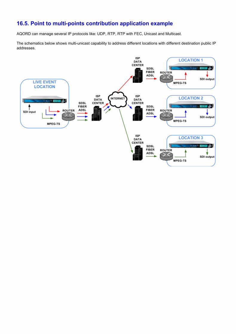
16.5. Point to multipoints contribution application example AQORD can manage several IP protocols like: UDP, RTP, RTP with FEC, Unicast and Multicast. The schematics below shows multiunicast capability to address different locations with different destination public IP addresses.
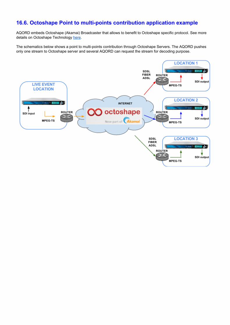
16.6. Octoshape Point to multipoints contribution application example AQORD embeds Octoshape (Akamai) Broadcaster that allows to benefit to Octoshape specific protocol. See more details on Octoshape Technology here. The schematics below shows a point to multipoints contribution through Octoshape Servers. The AQORD pushes only one stream to Octoshape server and several AQORD can request the stream for decoding purpose.

17. Glossary
Term Description CBR “Constant Bit Rate“: The encoding is done at a constant rate very close to the value of
"Video Rate" defined. BALANCED AUDIO Audio numeric interface. Connector used: XLR ETHERNET RJ45 connectors:
\ 10 BaseT : 10 Mb/s \ 100 BaseT : 100 Mb/s \ 1000 BaseT : 1000 Mb/s (Gigabit Ethernet)
GOP Groups of Pictures, which consist of keyframes and delta frames. FEC The ProMPEG CoP #3 FEC scheme uses the RTP transport protocol as a building block
for providing packet recovery techniques to ensure reliable realtime media transport. FIREFOX Web browser: http://www.firefox.com CHROME Web browser: https://www.google.com/chrome/ H.264/AVC H264 is a standard codec for video encoding. H264 allows two times more compression
than MPEG2 for the same image quality. HD High definition video HDD Hard Disk Drive MPEG Motion Picture Expert Group MPEG2 MPEG2 is a standard codec for video encoding MPEG2TS MPEG2 Transport Stream. Do not be confused with the MPEG2 Codec. PID An MPEG2TS is composed of video stream, audio stream, subtitles etc... Each of these
packages is composed of an elementary packet stream stamped with a unique identification number, or Packet IDentifier (PID)
PCR Program Clock Reference. In order for the decoder to synchronize to the correct decoding speed of the TS packet a PCR Packet is periodically inserted.
PMT Program Mapping Table. Identifies and shows different PID for each program contained in the MPEG2 TS stream.
SD Standard definition video SDI “Serial Digital Interface”, raw video interface using BNC 75 Ohms cable. Bit rate of 270
Mbits/s for SD video, 1.5Gbits/s for HD video (1080i) STREAMING The "streaming" function allows AQORD *LINK to send or receive video in real time over
the Ethernet network. During transmission the video is sent from the hard disk. During reception the video is stored on the hard disk.
Ta Ambient temperature TTL Time to live (TTL) is a mechanism that limits the lifetime of IP packet in a network. TTL is
implemented as a counter attached to IP packet and the value is reduced by every router on the route to its destination. Once the TTL value in a packet goes down to “0”, IP packet is discarded. In computer networking, TTL prevents a data packet from circulating indefinitely.
USB “Universal Serial Bus”. Standard of connection between a computer and its peripherals. VBR “Variable Bit Rate”: The encoding is done at a rate that varies depending on the video
content. The bit rate is maintained equal to or below the "Video Rate" defined.

DIGIGRAM Headquarters Serving Europe, Russia, the Middle East, Latin America and Africa Digigram S.A. 82/84 Allée Galilée (INOVALLEE) 38330 Montbonnot France Tel: +33 (0)4 76 52 47 47 Fax: +33 (0)4 76 52 18 44 Singapore Offices Serving Asia and Oceania Digigram Asia Pte Ltd 60 Albert Street #0911 OG Albert Complex Singapore 189969 Tel: +65/6291 2234 Fax: +65/6291 3433 http://video.digigram.com


![DHL Just Sell Redesign Wireframes v0 - kleinrogge.co.uk file[Link] [Link] [Link] [Link] [Link] [Link] [Link] [Link] [Link] [Link] [Link] [Link] [Link] [Link] [Link] [Link] [Link] [Link]](https://img.pdfslide.us/doc/110x75/5e01cdbb8c84236e132280ba/dhl-just-sell-redesign-wireframes-v0-link-link-link-link-link-link.jpg)