Embed Size (px)
Citation preview
(JUN10PHYA201)WMP/Jun10/PHYA2 PHYA2
Centre Number
Surname
Other Names
Candidate Signature
Candidate Number
General Certificate of EducationAdvanced Subsidiary ExaminationJune 2010
Time allowed● 1 hour 15 minutes
Instructions● Use black ink or black ball-point pen.● Fill in the boxes at the top of this page.● Answer all questions.● You must answer the questions in the spaces provided. Do not write
outside the box around each page or on blank pages.● Do all rough work in this book. Cross through any work you do not
want to be marked.
Information● The marks for questions are shown in brackets.● The maximum mark for this paper is 70.● You are expected to use a calculator where appropriate.● A Data and Formulae Book is provided as a loose insert.● You will be marked on your ability to:
– use good English– organise information clearly– use specialist vocabulary where appropriate.
For this paper you must have:
● a ruler● a calculator● a Data and Formulae Booklet.
Physics A PHYA2
Unit 2 Mechanics, Materials and Waves
Wednesday 9 June 2010 9.00 am to 10.15 am
MarkQuestion
For Examiner’s Use
Examiner’s Initials
TOTAL
1
2
3
4
5
6
7
WMP/Jun10/PHYA2
Do not writeoutside the
box
Answer all questions in the spaces provided.
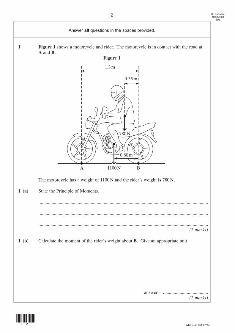
1 Figure 1 shows a motorcycle and rider. The motorcycle is in contact with the road at A and B.
Figure 1
The motorcycle has a weight of 1100 N and the rider’s weight is 780 N.
1 (a) State the Principle of Moments.
..............................................................................................................................................
..............................................................................................................................................
..............................................................................................................................................(2 marks)
1 (b) Calculate the moment of the rider’s weight about B. Give an appropriate unit.
answer = ......................................(2 marks)
(02)
2
0.35 m
1.3 m
1100 NA B
0.60 m
780 N
WMP/Jun10/PHYA2
Turn over �
(03)
Do not writeoutside the
box
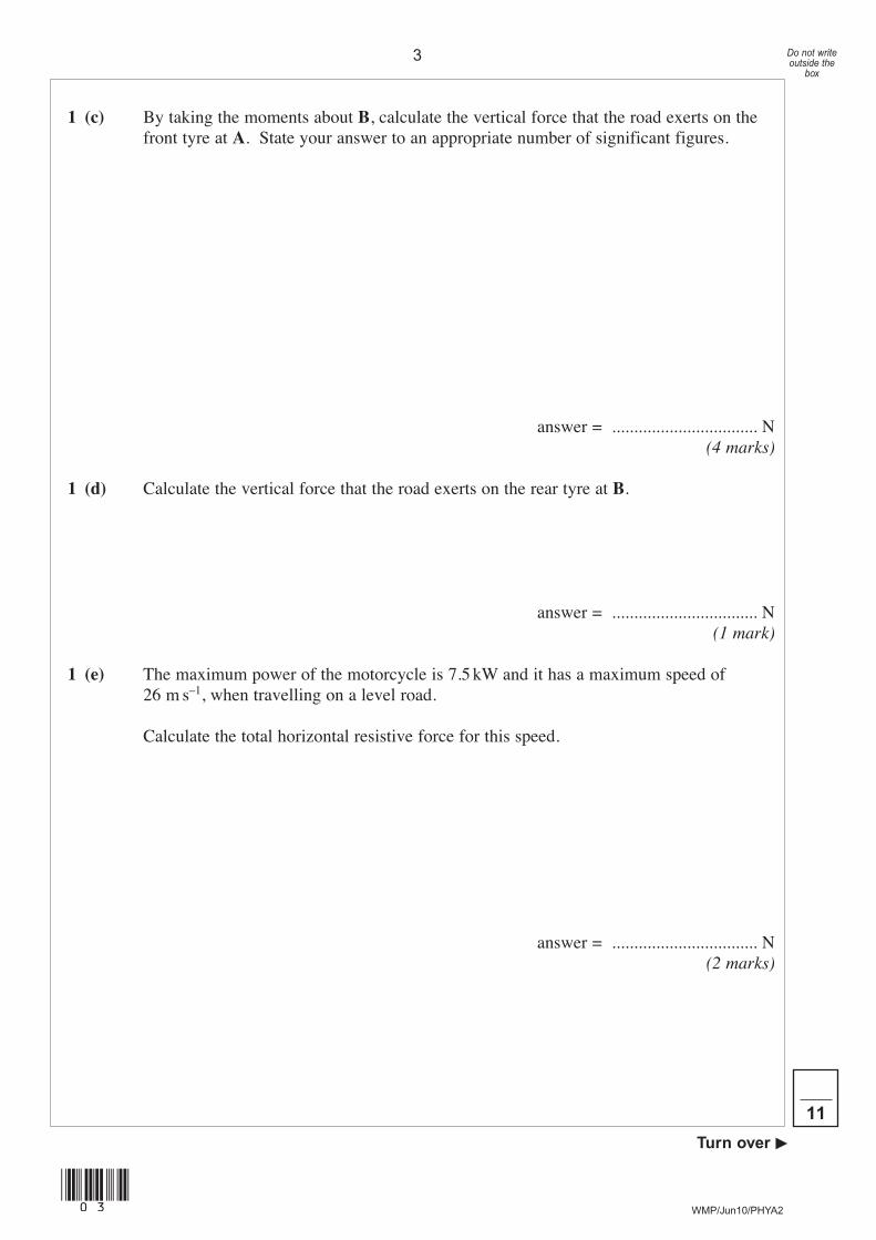
1 (c) By taking the moments about B, calculate the vertical force that the road exerts on thefront tyre at A. State your answer to an appropriate number of significant figures.
answer = ................................. N(4 marks)
1 (d) Calculate the vertical force that the road exerts on the rear tyre at B.
answer = ................................. N(1 mark)
1 (e) The maximum power of the motorcycle is 7.5 kW and it has a maximum speed of 26 m s–1, when travelling on a level road.
Calculate the total horizontal resistive force for this speed.
answer = ................................. N(2 marks)
3
11

WMP/Jun10/PHYA2(04)
4
There are no questions printed on this page
DO NOT WRITE ON THIS PAGEANSWER IN THE SPACES PROVIDED
WMP/Jun10/PHYA2
Do not writeoutside the
box
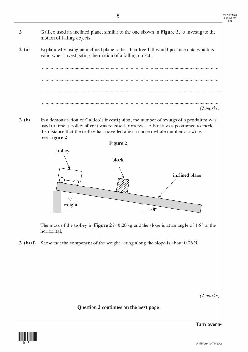
2 Galileo used an inclined plane, similar to the one shown in Figure 2, to investigate themotion of falling objects.
2 (a) Explain why using an inclined plane rather than free fall would produce data which isvalid when investigating the motion of a falling object.
..............................................................................................................................................
..............................................................................................................................................
..............................................................................................................................................
..............................................................................................................................................(2 marks)
2 (b) In a demonstration of Galileo’s investigation, the number of swings of a pendulum wasused to time a trolley after it was released from rest. A block was positioned to markthe distance that the trolley had travelled after a chosen whole number of swings.
See Figure 2.Figure 2
The mass of the trolley in Figure 2 is 0.20 kg and the slope is at an angle of 1·8º to thehorizontal.
2 (b) (i) Show that the component of the weight acting along the slope is about 0.06 N.
(2 marks)
Question 2 continues on the next page
5
(05)
1·8º
trolleyblock
weight
inclined plane
Turn over �
WMP/Jun10/PHYA2
Do not writeoutside the
box
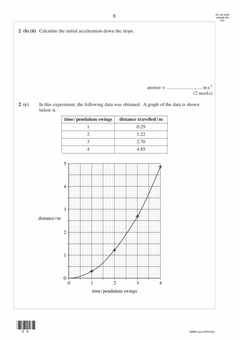
2 (b) (ii) Calculate the initial acceleration down the slope.
answer = ............................. m s-2
(2 marks)
2 (c) In this experiment, the following data was obtained. A graph of the data is shownbelow it.
6
(06)
time / pendulum swings distance travelled / m
1 0.29
2 1.22
3 2.70
4 4.85
00 1 2 3
time / pendulum swings4
1
2
3
4
5
distance / m
WMP/Jun10/PHYA2
Do not writeoutside the
box
2 (c) From the graph on page 6, state what you would conclude about the motion of thetrolley?
Give a reason for your answer.
..............................................................................................................................................
..............................................................................................................................................
..............................................................................................................................................
..............................................................................................................................................(2 marks)
2 (d) Each complete pendulum swing had a period of 1.4 s. Use the graph on page 6 to findthe speed of the trolley after it had travelled 3.0 m.
answer = ............................. m s-1
(3 marks)
Turn over for the next question
7
(07)
11
Turn over �
WMP/Jun10/PHYA2(08)
Do not writeoutside the
box
8
3 (a) Define the amplitude of a wave.
..............................................................................................................................................
..............................................................................................................................................(1 mark)
3 (b) (i) Other than electromagnetic radiation, give one example of a wave that is transverse.
..............................................................................................................................................(1 mark)
3 (b) (ii) State one difference between a transverse wave and a longitudinal wave.
..............................................................................................................................................
..............................................................................................................................................(1 mark)
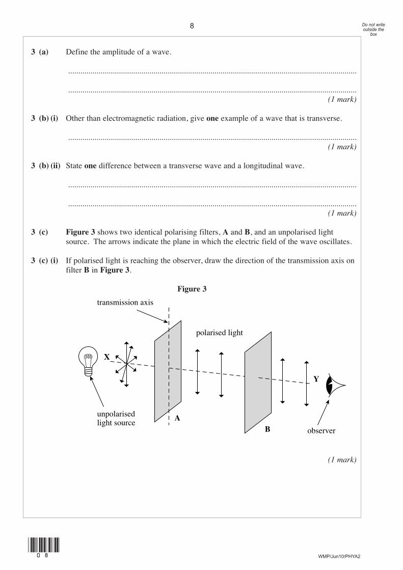
3 (c) Figure 3 shows two identical polarising filters, A and B, and an unpolarised lightsource. The arrows indicate the plane in which the electric field of the wave oscillates.
3 (c) (i) If polarised light is reaching the observer, draw the direction of the transmission axis onfilter B in Figure 3.
Figure 3
(1 mark)
transmission axis
observer
polarised light
unpolarisedlight source A
B
X
Y
WMP/Jun10/PHYA2
Do not writeoutside the
box
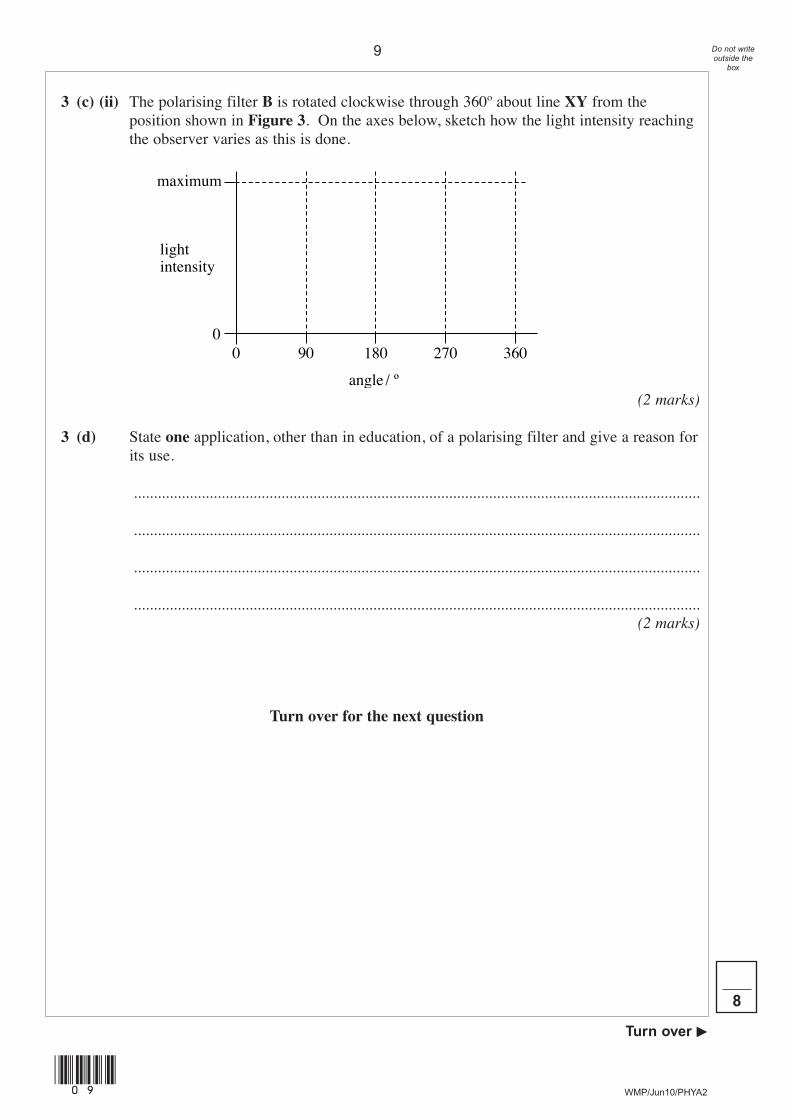
3 (c) (ii) The polarising filter B is rotated clockwise through 360º about line XY from theposition shown in Figure 3. On the axes below, sketch how the light intensity reachingthe observer varies as this is done.
(2 marks)
3 (d) State one application, other than in education, of a polarising filter and give a reason forits use.
..............................................................................................................................................
..............................................................................................................................................
..............................................................................................................................................
..............................................................................................................................................(2 marks)
Turn over for the next question
9
(09)
8
maximum
lightintensity
00
90 180angle / º
270 360
Turn over �
WMP/Jun10/PHYA2
Do not writeoutside the
box
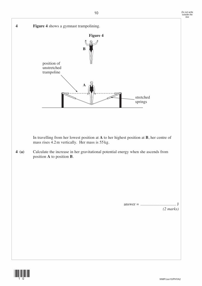
4 Figure 4 shows a gymnast trampolining.
Figure 4
In travelling from her lowest position at A to her highest position at B, her centre ofmass rises 4.2 m vertically. Her mass is 55 kg.
4 (a) Calculate the increase in her gravitational potential energy when she ascends fromposition A to position B.
answer = ................................... J(2 marks)
10
(10)
position ofunstretchedtrampoline
B
A
stretchedsprings
WMP/Jun10/PHYA2
Do not writeoutside the
box
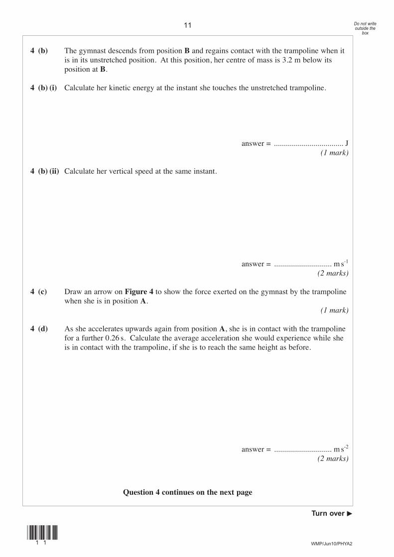
4 (b) The gymnast descends from position B and regains contact with the trampoline when itis in its unstretched position. At this position, her centre of mass is 3.2 m below itsposition at B.
4 (b) (i) Calculate her kinetic energy at the instant she touches the unstretched trampoline.
answer = ................................... J(1 mark)
4 (b) (ii) Calculate her vertical speed at the same instant.
answer = ............................. m s-1
(2 marks)
4 (c) Draw an arrow on Figure 4 to show the force exerted on the gymnast by the trampolinewhen she is in position A.
(1 mark)
4 (d) As she accelerates upwards again from position A, she is in contact with the trampolinefor a further 0.26 s. Calculate the average acceleration she would experience while sheis in contact with the trampoline, if she is to reach the same height as before.
answer = ............................. m s-2
(2 marks)
Question 4 continues on the next page
11
(11)Turn over �

WMP/Jun10/PHYA2
Do not writeoutside the
box
4 (e) On her next jump the gymnast decides to reach a height above position B. Describe andexplain, in terms of energy and work, the transformations that occur as she ascendsfrom her lowest position A until she reaches her new position above B.
The quality of your written communication will be assessed in this question.
..............................................................................................................................................
..............................................................................................................................................
..............................................................................................................................................
..............................................................................................................................................
..............................................................................................................................................
..............................................................................................................................................
..............................................................................................................................................
..............................................................................................................................................
..............................................................................................................................................
..............................................................................................................................................
..............................................................................................................................................
..............................................................................................................................................(6 marks)
12
(12)
14
WMP/Jun10/PHYA2
Do not writeoutside the
box
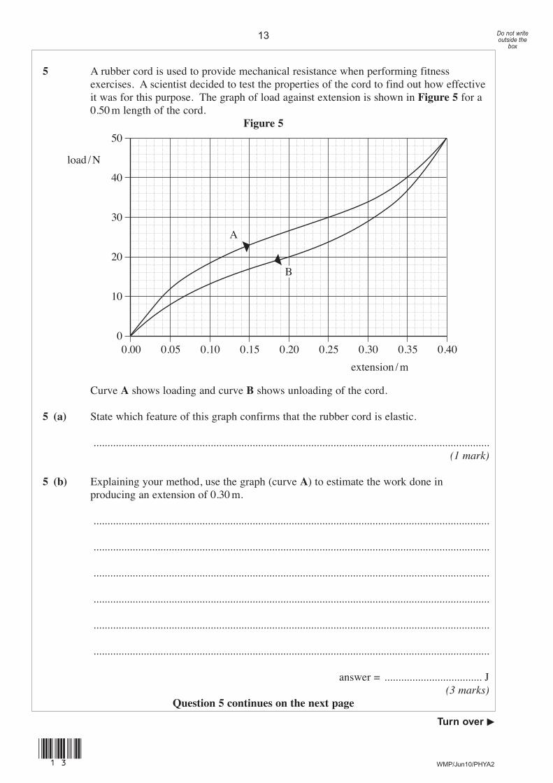
5 A rubber cord is used to provide mechanical resistance when performing fitnessexercises. A scientist decided to test the properties of the cord to find out how effectiveit was for this purpose. The graph of load against extension is shown in Figure 5 for a0.50 m length of the cord.
Figure 5
Curve A shows loading and curve B shows unloading of the cord.
5 (a) State which feature of this graph confirms that the rubber cord is elastic.
..............................................................................................................................................(1 mark)
5 (b) Explaining your method, use the graph (curve A) to estimate the work done inproducing an extension of 0.30 m.
..............................................................................................................................................
..............................................................................................................................................
..............................................................................................................................................
..............................................................................................................................................
..............................................................................................................................................
..............................................................................................................................................
answer = ................................... J(3 marks)
Question 5 continues on the next page
13
(13)
00.00 0.10 0.20 0.30
extension / m
0.400.05 0.15 0.25 0.35
20
40
load / N
10
30
50
A
B
Turn over �
WMP/Jun10/PHYA2
Do not writeoutside the
box
5 (c) Assuming that line A is linear up to an extension of 0.040 m, calculate the Youngmodulus of the rubber for small strains.
The cross-sectional area of the cord = 5.0 x 10⁻⁶ m2
The unstretched length of the cord = 0.50 m
answer = ................................ Pa(3 marks)
5 (d) The scientist compared this cord with a steel spring that reached the same extension forthe same maximum load without exceeding its limit of proportionality.
5 (d) (i) On Figure 5, draw the load-extension line for this spring up to a load of 50 N and labelit C.
(1 mark)
5 (d) (ii) With reference to the spring, explain what is meant by limit of proportionality.
..............................................................................................................................................
..............................................................................................................................................(1 mark)
14
(14)
9
WMP/Jun10/PHYA2
Do not writeoutside the
box
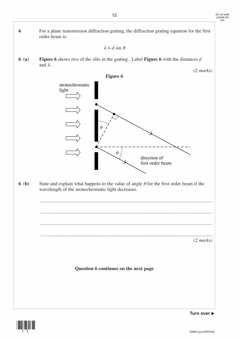
6 For a plane transmission diffraction grating, the diffraction grating equation for the firstorder beam is:
λ = d sin θ
6 (a) Figure 6 shows two of the slits in the grating. Label Figure 6 with the distances d and λ.
(2 marks)Figure 6
6 (b) State and explain what happens to the value of angle θ for the first order beam if thewavelength of the monochromatic light decreases.
..............................................................................................................................................
..............................................................................................................................................
..............................................................................................................................................
..............................................................................................................................................(2 marks)
Question 6 continues on the next page
15
(15)
monochromaticlight
direction offirst order beam
θ
θ
Turn over �
WMP/Jun10/PHYA2
Do not writeoutside the
box
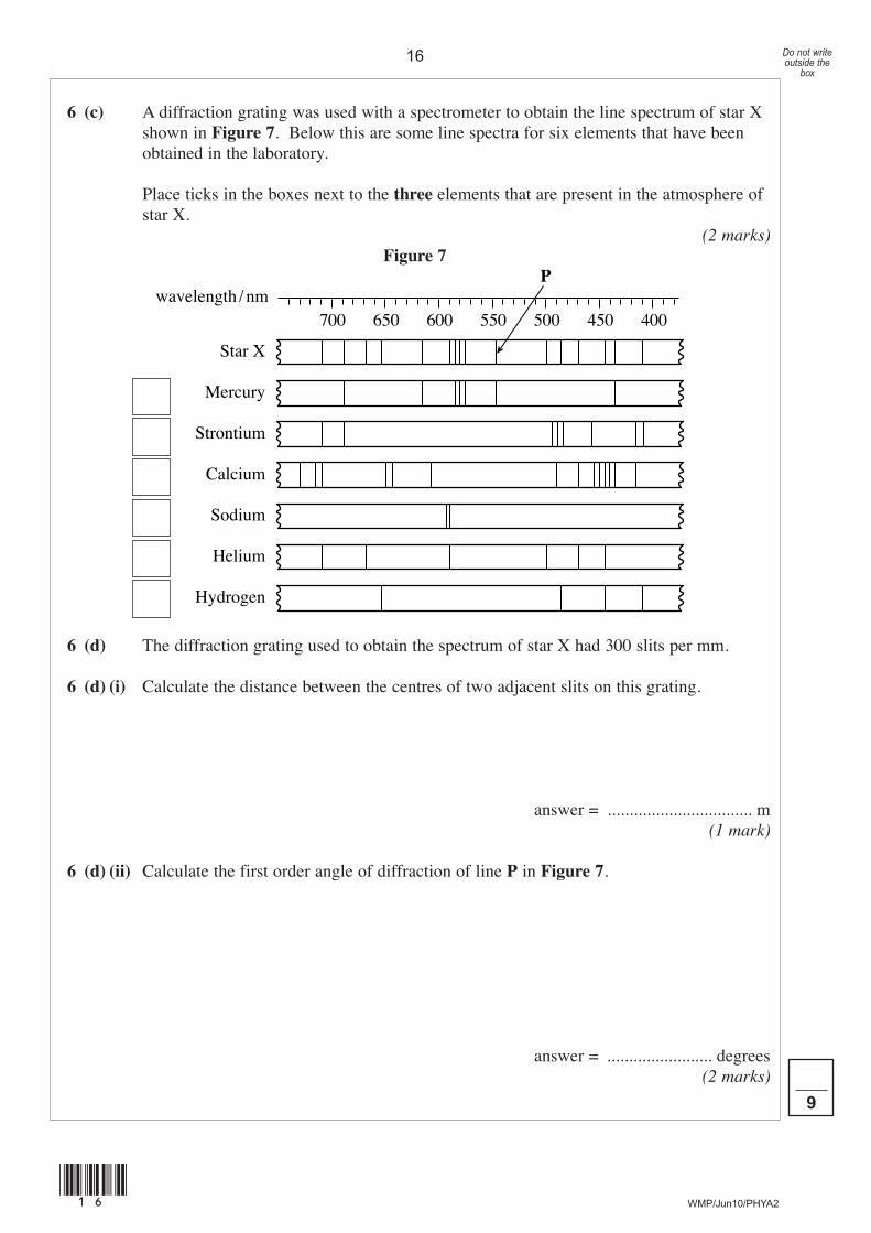
6 (c) A diffraction grating was used with a spectrometer to obtain the line spectrum of star Xshown in Figure 7. Below this are some line spectra for six elements that have beenobtained in the laboratory.
Place ticks in the boxes next to the three elements that are present in the atmosphere ofstar X.
(2 marks)Figure 7
6 (d) The diffraction grating used to obtain the spectrum of star X had 300 slits per mm.
6 (d) (i) Calculate the distance between the centres of two adjacent slits on this grating.
answer = ................................. m(1 mark)
6 (d) (ii) Calculate the first order angle of diffraction of line P in Figure 7.
answer = ........................ degrees(2 marks)
16
(16)
9
700 650 600 550 500 450 400wavelength / nm
Star X
Mercury
Strontium
Calcium
Sodium
Helium
Hydrogen
P
WMP/Jun10/PHYA2
Do not writeoutside the
box
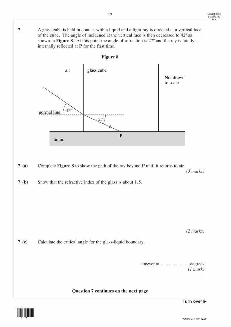
7 A glass cube is held in contact with a liquid and a light ray is directed at a vertical faceof the cube. The angle of incidence at the vertical face is then decreased to 42º asshown in Figure 8. At this point the angle of refraction is 27º and the ray is totallyinternally reflected at P for the first time.
Figure 8
7 (a) Complete Figure 8 to show the path of the ray beyond P until it returns to air.
(3 marks)
7 (b) Show that the refractive index of the glass is about 1. 5.
(2 marks)
7 (c) Calculate the critical angle for the glass-liquid boundary.
answer = ........................ degrees(1 mark)
Question 7 continues on the next page
17
(17)
normal line
glass cubeNot drawnto scale
liquid P
air
42º
27º
Turn over �
WMP/Jun10/PHYA2
Do not writeoutside the
box
7 (d) Calculate the refractive index of the liquid.
answer = .....................................(2 marks)
END OF QUESTIONS
18
(18)
8

WMP/Jun10/PHYA2(19)
19
There are no questions printed on this page
DO NOT WRITE ON THIS PAGEANSWER IN THE SPACES PROVIDED
Turn over �

WMP/Jun10/PHYA2(20)
Do not writeoutside the
box
20
There are no questions printed on this page
DO NOT WRITE ON THIS PAGEANSWER IN THE SPACES PROVIDED
Copyright © 2010 AQA and its licensors. All rights reserved.


![Report Jun10 [PalTrade -- Trade Agreements]](https://img.pdfslide.us/doc/110x75/577d378f1a28ab3a6b95e102/report-jun10-paltrade-trade-agreements.jpg)