Embed Size (px)
Citation preview
INSTRUCTIONS
8.625
8.625
1/8" DRILL BIT
TAPE MEASURE
DRILL
UPTO 1" TO LEVEL THE TOP AS NEEDED.
STEP 1: CHECK BOTTOM SIDE OF TOP FOR PRE BORED MOUNTING HOLES (IF DONE MOVE TO STEP 4)
STEP 2: IF TOP ORDERED DOES NOT HAVE PREBORED MOUNTING HOLES, PLACE TOP UPSIDE DOWN ON A PROTECTIVE SURFACE AND LOCATE DUOFOIL LEGS AT A 45 ANGLE TO EDGE OF TOP WITH WIRE CAVITY FACING TORWARD KNEESPACE AT A DISTANCE OF 8 5/8" FROM EDGE OF TOP TO THE CENTER OF THE MOUNTING PLATES BACK EDGE (SEE ILLUSTRATION BELOW)AND MARK LOCATION OF EACH HOLE USING MOUNT PLATE HOLES AS LOCATION GUIDE.
STEP 3: AFTER MARKING MOUNTING PLATE HOLE LOCATIONS REMOVE DUOFOIL LEGS AND PREBORE 1/8" X 13/16" DEEP HOLES AT PREVIOUSLY MARKED LOCATIONS.
STEP 4: ATTACH DUOFOIL LEGS TO BOTTOM SIDE OF TOP (WIRE CAVITY FACING KNEESPACE) WITH HK-98, ALIGNING HOLES IN MOUNT PLATE WITH PRE-BORED HOLES IN TOP.
STEP 5: LEVELER IN BOTTOM OF DUOFOIL LEGS CAN BE ADJUSTED OUT
DUOFOIL LEGS
Rev:Dwg:
STEP 2 & 3: TO LOCATE LEGS IN NON PREBORED TOP
45°
45°
WIRE CAVITY
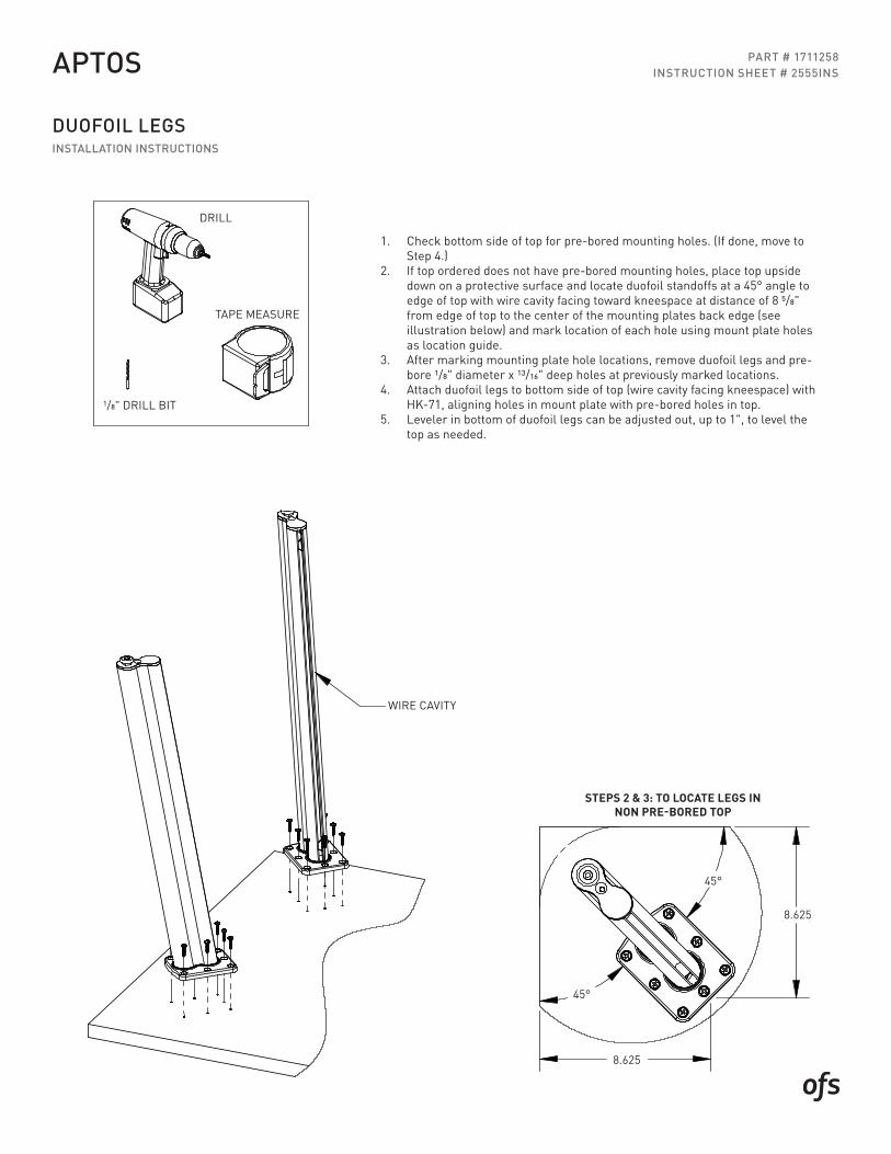
PART # 1711258INSTRUCTION SHEET # 2555INS
DUOFOIL LEGSINSTALLATION INSTRUCTIONS
APTOS
1. Check bottom side of top for pre-bored mounting holes. (If done, move to Step 4.)
2. If top ordered does not have pre-bored mounting holes, place top upside down on a protective surface and locate duofoil standoffs at a 45° angle to edge of top with wire cavity facing toward kneespace at distance of 8 5/8" from edge of top to the center of the mounting plates back edge (see illustration below) and mark location of each hole using mount plate holes as location guide.
3. After marking mounting plate hole locations, remove duofoil legs and pre-bore 1/8" diameter x 13/16" deep holes at previously marked locations.
4. Attach duofoil legs to bottom side of top (wire cavity facing kneespace) with HK-71, aligning holes in mount plate with pre-bored holes in top.
5. Leveler in bottom of duofoil legs can be adjusted out, up to 1", to level the top as needed.
INSTRUCTIONS
8.625
8.625
1/8" DRILL BIT
TAPE MEASURE
DRILL
UPTO 1" TO LEVEL THE TOP AS NEEDED.
STEP 1: CHECK BOTTOM SIDE OF TOP FOR PRE BORED MOUNTING HOLES (IF DONE MOVE TO STEP 4)
STEP 2: IF TOP ORDERED DOES NOT HAVE PREBORED MOUNTING HOLES, PLACE TOP UPSIDE DOWN ON A PROTECTIVE SURFACE AND LOCATE DUOFOIL LEGS AT A 45 ANGLE TO EDGE OF TOP WITH WIRE CAVITY FACING TORWARD KNEESPACE AT A DISTANCE OF 8 5/8" FROM EDGE OF TOP TO THE CENTER OF THE MOUNTING PLATES BACK EDGE (SEE ILLUSTRATION BELOW)AND MARK LOCATION OF EACH HOLE USING MOUNT PLATE HOLES AS LOCATION GUIDE.
STEP 3: AFTER MARKING MOUNTING PLATE HOLE LOCATIONS REMOVE DUOFOIL LEGS AND PREBORE 1/8" X 13/16" DEEP HOLES AT PREVIOUSLY MARKED LOCATIONS.
STEP 4: ATTACH DUOFOIL LEGS TO BOTTOM SIDE OF TOP (WIRE CAVITY FACING KNEESPACE) WITH HK-98, ALIGNING HOLES IN MOUNT PLATE WITH PRE-BORED HOLES IN TOP.
STEP 5: LEVELER IN BOTTOM OF DUOFOIL LEGS CAN BE ADJUSTED OUT
DUOFOIL LEGS
Rev:Dwg:
STEP 2 & 3: TO LOCATE LEGS IN NON PREBORED TOP
45°
45°
WIRE CAVITY
STEPS 2 & 3: TO LOCATE LEGS IN NON PRE-BORED TOP
WIRE CAVITY
8.625
45°
8.625
TAPE MEASURETAPE MEASURE
1/8" DRILL BIT
DRILL
45°
INSTRUCTIONS
8.625
8.625
1/8" DRILL BIT
TAPE MEASURE
DRILL
UPTO 1" TO LEVEL THE TOP AS NEEDED.
STEP 1: CHECK BOTTOM SIDE OF TOP FOR PRE BORED MOUNTING HOLES (IF DONE MOVE TO STEP 4)
STEP 2: IF TOP ORDERED DOES NOT HAVE PREBORED MOUNTING HOLES, PLACE TOP UPSIDE DOWN ON A PROTECTIVE SURFACE AND LOCATE DUOFOIL LEGS AT A 45 ANGLE TO EDGE OF TOP WITH WIRE CAVITY FACING TORWARD KNEESPACE AT A DISTANCE OF 8 5/8" FROM EDGE OF TOP TO THE CENTER OF THE MOUNTING PLATES BACK EDGE (SEE ILLUSTRATION BELOW)AND MARK LOCATION OF EACH HOLE USING MOUNT PLATE HOLES AS LOCATION GUIDE.
STEP 3: AFTER MARKING MOUNTING PLATE HOLE LOCATIONS REMOVE DUOFOIL LEGS AND PREBORE 1/8" X 13/16" DEEP HOLES AT PREVIOUSLY MARKED LOCATIONS.
STEP 4: ATTACH DUOFOIL LEGS TO BOTTOM SIDE OF TOP (WIRE CAVITY FACING KNEESPACE) WITH HK-98, ALIGNING HOLES IN MOUNT PLATE WITH PRE-BORED HOLES IN TOP.
STEP 5: LEVELER IN BOTTOM OF DUOFOIL LEGS CAN BE ADJUSTED OUT
DUOFOIL LEGS
Rev:Dwg:
STEP 2 & 3: TO LOCATE LEGS IN NON PREBORED TOP
45°
45°
WIRE CAVITY
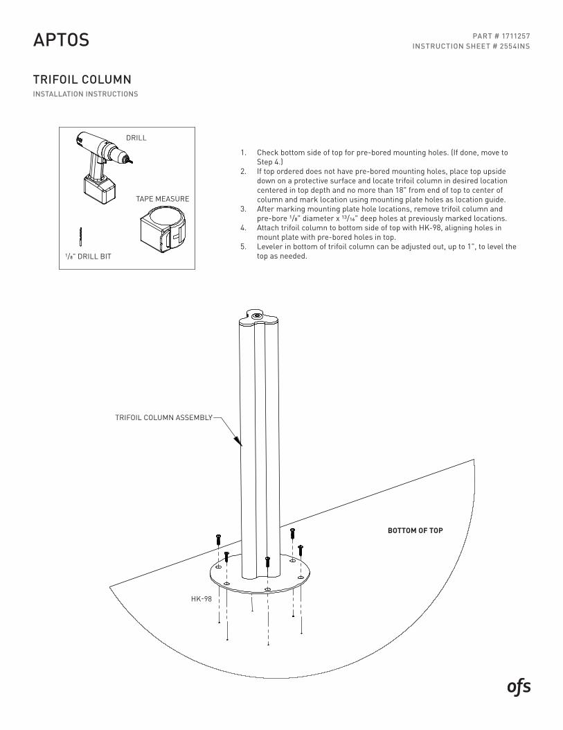
PART # 1711257INSTRUCTION SHEET # 2554INS
TRIFOIL COLUMNINSTALLATION INSTRUCTIONS
APTOS
1. Check bottom side of top for pre-bored mounting holes. (If done, move to Step 4.)
2. If top ordered does not have pre-bored mounting holes, place top upside down on a protective surface and locate trifoil column in desired location centered in top depth and no more than 18" from end of top to center of column and mark location using mounting plate holes as location guide.
3. After marking mounting plate hole locations, remove trifoil column and pre-bore 1/8" diameter x 13/16" deep holes at previously marked locations.
4. Attach trifoil column to bottom side of top with HK-98, aligning holes in mount plate with pre-bored holes in top.
5. Leveler in bottom of trifoil column can be adjusted out, up to 1", to level the top as needed.
INSTRUCTIONS
BOTTOM OF TOP
TRIFOIL COLUMN ASSEMBLY
HK-98
TRIFOIL COLUMN
STEP 1: CHECK BOTTOM SIDE OF TOP FOR PRE BORED MOUNTING HOLES (IF DONE MOVE TO STEP 5)
STEP 2: IF TOP ORDERED DOES NOT HAVE PREBORED MOUNTING HOLES, PLACE TOP UPSIDE DOWN ON A PROTECTIVE SURFACE AND LOCATE TRIFOIL COLUMN IN DESIRED LOCATION CENTERED IN TOP DEPTH AND NO MORE THAN 18" FROM END OF TOP TO CENTER OF COLUMN AND MARK LOCATION USING MOUNT PLATE HOLES AS LOCATION GUIDE.
STEP 3: AFTER MARKING MOUNTING PLATE HOLE LOCATIONS REMOVE TRIFOIL COLUMN AND PREBORE 1/8" X 13/16" DEEP HOLES AT PREVIOUSLY MARKED LOCATIONS.
STEP 4: ATTACH TRIFOIL COLUMN TO BOTTOM SIDE OF TOP WITH HK-98, ALIGNING HOLES IN MOUNT PLATE WITH PRE-BORED HOLES IN TOP.
STEP 5: LEVELER IN BOTTOM OF TRIFOIL COLUMN CAN BE ADJUSTED OUT UPTO 1" TO LEVEL THE TOP AS NEEDED.
Dwg: Rev: 2554INS
DRILL
TAPE MEASURE
1/8" DRILL BIT
TRIFOIL COLUMN ASSEMBLY
HK-98
TAPE MEASURETAPE MEASURE
1/8" DRILL BIT
DRILL
BOTTOM OF TOP

INSTRUCTIONS
* With top upside down on a protective surface install both Duofoil standoffs and the runoff support (Trifoil column, Duofoil legs, Runoff end panel)using the instructions & hardware supplied with each item.* Aligning the holes in the mounting plates with the pre-bored holes in the top. Position the wire cavity so that it faces the knee space of the top.* The Duofoil pieces will be rotated at a 45 angle
Dwg: Rev: 2567INS - PAGE 1
ELEVATED RUNOFF TOP INSTALLATION
* Measure the center to center distance of the mounting studs on the Duofoil standoffs.* This measurement will be used to bore the mounting holes in the top of the low height cabinet in the next step.
Center line of top
XX
PART # 1699910INSTRUCTION SHEET # 2567INS
ELEVATED RUNOFF TOPINSTALLATION INSTRUCTIONS
APTOS
CENTER LINE OF TOP
XX
3. The Duofoil pieces will be rotated at a 45 angle.4. Measure the center to center distance of the
mounting studs on the Duofoil standoffs.5. This measurement will be used to bore the
mounting holes in the top of the low height cabinet in the next step.
1. With top upside down on a protective surface install both Duofoil standoffs and the runoff support (Trifoil column, Duofoil legs, Runoff end panel) using the instructions & hardware supplied with each item.
2. Aligning the holes in the mounting plates with the pre-bored holes in the top. Position the wire cavity so that it faces the knee space of the top.
INSTRUCTIONS
XX/2 XX/2
XX(C-C of standoffmounting studs)
Dwg: Rev:2567INS - PAGE 2
* Verify that the marked locations of the standoff mounting holes are not located over a divider panel or end panel. If they are shift location of top to clear obstructions.* Tape off area to be drilled to help protect the finished surface. Center punch the 2 locating holes to be bored.* Bore the 2 mounting holes for the standoffs using a 3/8" drill bit thru the top of the low height cabinet.* Remove tape and carefully install the elevated runoff top being careful not to scratch the finished top surface of the low height cabinet when placing the studs into the bored holes.* Once the elevated runoff top is placed secure it with the washer and nut supplied with the standoffs.* Level top with the adjustable leveler in the runoff end support.
* Determine application (open plan or private office), open plan is located 3.5" off front edge of cabinet, private office is located 9" off the back edge of the cabinet.* Locate desired placement side to side on the low height cabinet and mark the center line location of the elevated runoff top.* Divide the C-C measurement peviously taken from the standoffs on the elevated runoff top & divide it by 2.* Measure this distance both ways from the top center line along with the front to back dimension (3.5" or 9") depending on the application to find center points of the standoffs.
Locate center line of eleveated runoff top
9Private Office
3.5Open Plan
PART # 1699910INSTRUCTION SHEET # 2567INS
ELEVATED RUNOFF TOPINSTALLATION INSTRUCTIONS
APTOS
LOCATE CENTER LINE OF ELEVATED RUNOFF TOP
9"PRIVATE OFFICE
3.5"OPEN PLAN
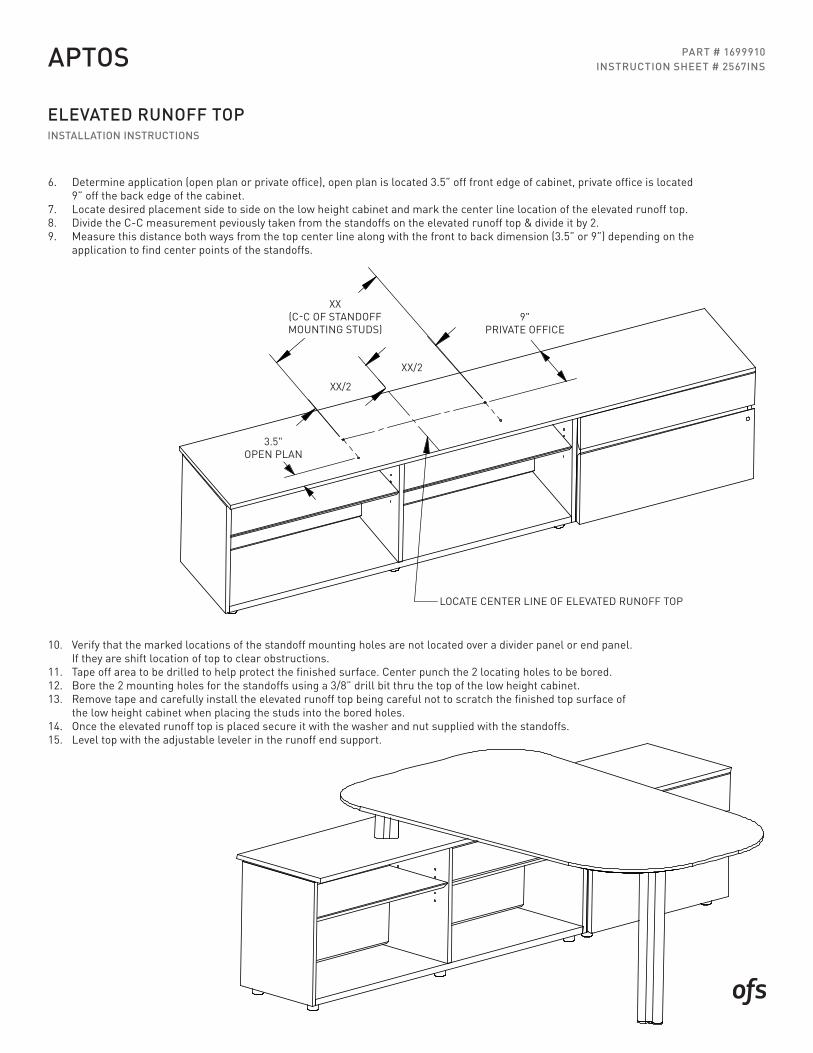
6. Determine application (open plan or private office), open plan is located 3.5” off front edge of cabinet, private office is located 9” off the back edge of the cabinet.
7. Locate desired placement side to side on the low height cabinet and mark the center line location of the elevated runoff top.8. Divide the C-C measurement peviously taken from the standoffs on the elevated runoff top & divide it by 2.9. Measure this distance both ways from the top center line along with the front to back dimension (3.5” or 9”) depending on the
application to find center points of the standoffs.
10. Verify that the marked locations of the standoff mounting holes are not located over a divider panel or end panel. If they are shift location of top to clear obstructions.
11. Tape off area to be drilled to help protect the finished surface. Center punch the 2 locating holes to be bored.12. Bore the 2 mounting holes for the standoffs using a 3/8” drill bit thru the top of the low height cabinet.13. Remove tape and carefully install the elevated runoff top being careful not to scratch the finished top surface of
the low height cabinet when placing the studs into the bored holes.14. Once the elevated runoff top is placed secure it with the washer and nut supplied with the standoffs.15. Level top with the adjustable leveler in the runoff end support.
XX(C-C OF STANDOFFMOUNTING STUDS)
XX/2
XX/2
INSTRUCTIONS
TAPE MEASUREDRILL
WIRE CAVITY
MOUNTING LOCATIONS FOR MODULAR TOPSBEING USED IN AN ELEVATED APPLICATION
2" FOR 24"D TOPS1" FOR 18"D TOPS
4.875
BOTTOMSIDE
ANGLE TO THE EDGE
FOR LOCATIONS.
DUOFOIL STANDOFFS
OF THE TOP WITH THE WIRE CAVITY SLOT FACING
STEP 4: REPEAT STEPS 1-3 FOR REMAINING STAND OFFS.
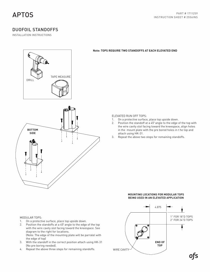
NOTE: TOPS REQUIRE TWO STANDOFFS AT EACH ELEVATED END
NOTE: THE EDGE OF THE MOUNTING PLATE WILL BE PARRALEL
TORWARD THE KNEESPACE. SEE DIAGRAM TO THE RIGHT
WITH THE EDGE OF TOP
USING HK-31. (NO PRE BORING NEEDED).STEP 3: WITH THE STANDOFF IN THE CORRECT POSITION ATTACH
MODULAR TOPS:STEP 1: ON A PROTECTIVE SURFACE, PLACE TOP UPSIDE DOWN.STEP 2: POSITION THE STANDOFFS AT A 45
ELEVATED RUN OFF TOPS:STEP 1: ON A PROTECTIVE SURFACE, PLACE TOP UPSIDE DOWN.
STEP 2: POSITION THE STANDOFF AT A 45 ANGLE TO THE EDGE OF THE TOP WITH THE WIRE CAVITY SLOT FACING TOWARD THE KNEESPACE, ALIGN HOLES IN THE MOUNT PLATE WITH THE PRE BORED HOLES IN THE TOP & ATTACH USING HK-31.STEP 3: REPEAT STEPS 1-2 FOR REMAINING STAND OFFS.
Dwg: Rev: 2556INS
PART # 1711259INSTRUCTION SHEET # 2556INS
DUOFOIL STANDOFFSINSTALLATION INSTRUCTIONS
APTOS
INSTRUCTIONS
TAPE MEASUREDRILL
WIRE CAVITY
MOUNTING LOCATIONS FOR MODULAR TOPSBEING USED IN AN ELEVATED APPLICATION
2" FOR 24"D TOPS1" FOR 18"D TOPS
4.875
BOTTOMSIDE
ANGLE TO THE EDGE
FOR LOCATIONS.
DUOFOIL STANDOFFS
OF THE TOP WITH THE WIRE CAVITY SLOT FACING
STEP 4: REPEAT STEPS 1-3 FOR REMAINING STAND OFFS.
NOTE: TOPS REQUIRE TWO STANDOFFS AT EACH ELEVATED END
NOTE: THE EDGE OF THE MOUNTING PLATE WILL BE PARRALEL
TORWARD THE KNEESPACE. SEE DIAGRAM TO THE RIGHT
WITH THE EDGE OF TOP
USING HK-31. (NO PRE BORING NEEDED).STEP 3: WITH THE STANDOFF IN THE CORRECT POSITION ATTACH
MODULAR TOPS:STEP 1: ON A PROTECTIVE SURFACE, PLACE TOP UPSIDE DOWN.STEP 2: POSITION THE STANDOFFS AT A 45
ELEVATED RUN OFF TOPS:STEP 1: ON A PROTECTIVE SURFACE, PLACE TOP UPSIDE DOWN.
STEP 2: POSITION THE STANDOFF AT A 45 ANGLE TO THE EDGE OF THE TOP WITH THE WIRE CAVITY SLOT FACING TOWARD THE KNEESPACE, ALIGN HOLES IN THE MOUNT PLATE WITH THE PRE BORED HOLES IN THE TOP & ATTACH USING HK-31.STEP 3: REPEAT STEPS 1-2 FOR REMAINING STAND OFFS.
Dwg: Rev: 2556INS
BOTTOM SIDE
MOUNTING LOCATIONS FOR MODULAR TOPS BEING USED IN AN ELEVATED APPLICATION
WIRE CAVITY
4.875
1" FOR 18"D TOPS2" FOR 24"D TOPS
Note: TOPS REQUIRE TWO STANDOFFS AT EACH ELEVATED END
TAPE MEASUREDRILL
ELEVATED RUN OFF TOPS:1. On a protective surface, place top upside down.2. Position the standoff at a 450 angle to the edge of the top with
the wire cavity slot facing toward the kneespace, align holes in the mount plate with the pre bored holes in t he top and attach using HK-31.
3. Repeat the above two steps for remaining standoffs.
MODULAR TOPS:1. On a protective surface, place top upside down.2. Position the standoffs at a 450 angle to the edge of the top
with the wire cavity slot facing toward the kneespace. See diagram to the right for locations. (Note: The edge of the mounting plate will be parralel with the edge of top)
3. With the standoff in the correct position attach using HK-31 (No pre boring needed).
4. Repeat the above three steps for remaining standoffs.
END OF TOP
INSTRUCTIONS
HK-98(8) #12 X 1" SCREWS
BOTTOMOF TOP
1. WITH TOP UPSIDE DOWN ON A PROTECTIVE SURFACE PLACE END PANEL ASSEMBLY ON TOP AS SHOWN (CENTERED SIDE TO SIDE), INSET 1/8" FROM OUTER END OF TOP & ATTACH WITH HK-98.
Rev: Dwg: 2549INS
PART # 1697663INSTRUCTION SHEET # 2549INS
END PANELASSEMBLY INSTRUCTIONS
APTOS
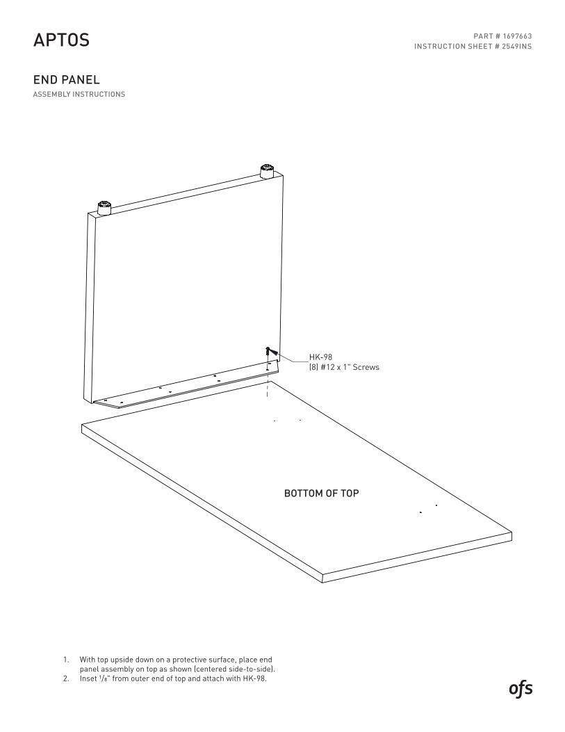
1. With top upside down on a protective surface, place end panel assembly on top as shown (centered side-to-side).
2. Inset 1/8" from outer end of top and attach with HK-98.
HK-98(8) #12 x 1" Screws
BOTTOM OF TOP
PART # 1711256INSTRUCTION SHEET # 2553INS
HEIGHT ADJUSTABLE CREDENZAINSTALLATION INSTRUCTIONS
APTOS
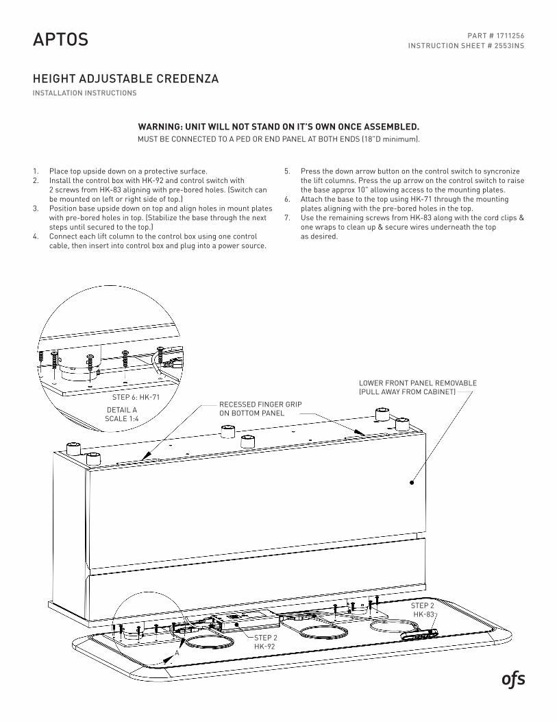
1. Place top upside down on a protective surface.2. Install the control box with HK-92 and control switch with
2 screws from HK-83 aligning with pre-bored holes. (Switch can be mounted on left or right side of top.)
3. Position base upside down on top and align holes in mount plates with pre-bored holes in top. (Stabilize the base through the next steps until secured to the top.)
4. Connect each lift column to the control box using one control cable, then insert into control box and plug into a power source.
5. Press the down arrow button on the control switch to syncronize the lift columns. Press the up arrow on the control switch to raise the base approx 10" allowing access to the mounting plates.
6. Attach the base to the top using HK-71 through the mounting plates aligning with the pre-bored holes in the top.
7. Use the remaining screws from HK-83 along with the cord clips & one wraps to clean up & secure wires underneath the top as desired.
WARNING: UNIT WILL NOT STAND ON IT’S OWN ONCE ASSEMBLED.MUST BE CONNECTED TO A PED OR END PANEL AT BOTH ENDS (18”D minimum).
STEP 2HK-92
STEP 2HK-83
A
LOWER FRONT PANEL REMOVABLE(PULL AWAY FROM CABINET)
RECESSED FINGER GRIP ON BOTTOM PANELDETAIL A
SCALE 1:4
STEP 6: HK-71
PART # 1711256INSTRUCTION SHEET # 2553INS
HEIGHT ADJUSTABLE CREDENZA ATTACHING TO ADJOINING CABINETINSTALLATION INSTRUCTIONS
APTOS
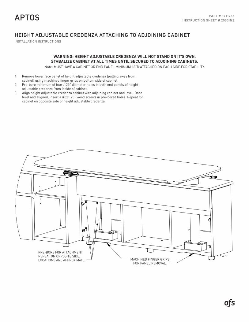
1. Remove lower face panel of height adjustable credenza (pulling away from cabinet) using machined finger grips on bottom side of cabinet.
2. Pre-bore minimum of four .125" diameter holes in both end panels of height adjustable credenza from inside of cabinet.
3. Align height adjustable credenza cabinet with adjoining cabinet and level. Once level and aligned, insert 4 #8x1.25" wood screws in pre-bored holes. Repeat for cabinet on opposite side of height adjustable credenza.
WARNING: HEIGHT ADJUSTABLE CREDENZA WILL NOT STAND ON IT’S OWN.STABALIZE CABINET AT ALL TIMES UNTIL SECURED TO ADJOINING CABINETS.
Note: MUST HAVE A CABINET OR END PANEL MINIMUM 18”D ATTACHED ON EACH SIDE FOR STABILITY.
INSTRUCTIONS
ATTACHING HEIGHT ADJUSTABLE CREDENZA TO ADJOINING CABINET
*** WARNING - Height adjustable credenza will not stand on it's own. Stabalize cabinet at all times until secured to adjoining cabinets. ***
for panel removal
NOTE: Must have a cabinet or end panel minimum 18"D attached on each side for stability.
Machined finger grips
* Remove lower face panel of height adjustable credenza (pulling away from cabinet) using machined finger grips
wood screws in pre-bored holes. Repeat for cabinet on opposite side of height adjustable credenza.
on bottom side of cabinet.* Pre-bore minimum of four .125" holes in both end panels of height adjustable credenza from inside of cabinet.
* Align height adjustable credenza cabinet with adjoining cabinet and level. Once level and aligned insert 4 #8 x 1.25"
pre-bore for attachmentrepeat on opposite side,locations are approximate.
2553INS - Page 2 Rev: _Dwg:
MACHINED FINGER GRIPS FOR PANEL REMOVAL.
PRE-BORE FOR ATTACHMENT REPEAT ON OPPOSITE SIDE, LOCATIONS ARE APPROXIMATE.
INSTRUCTIONS
REMOVABLE PANEL
REMOVABLE PANEL ASSEMBLEDFACING KNEESPACE
FINGER GRIP FORREMOVABLE PANEL
DRILL
4MM ALLEN WRENCH
TO ASSEMBLY POSITION AS SHOWN AND RE ATTACH.
HEIGHT ADJUSTABLE PENINSULA DESK
STEP 2: REMOVE MOUNT PLATE ON RUNOFF BASE AND ROTATE 90 FROM SHIPPING POSITION
NOTE: 2 PERSON INSTALL
STEP 1: LOCATE WALL CABINET IN DESIRED LOCATION & LEVEL. REMOVE SCREWS FROM ADJUSTABLE SHELF CLIPS FOR ACCESS TO FLIP DOWN BACK PANEL IN OPEN STORAGE AREA. (THE LOWER FRONT OF THE LIFT COLUMN CAVITY IS REMOVABLE BY PULLING PANEL AWAY FROM THE CABINET)
Rev:Dwg:
PART # 1711255INSTRUCTION SHEET # 2552INS
HEIGHT ADJUSTABLE PENINSULA DESKINSTALLATION INSTRUCTIONS
APTOS
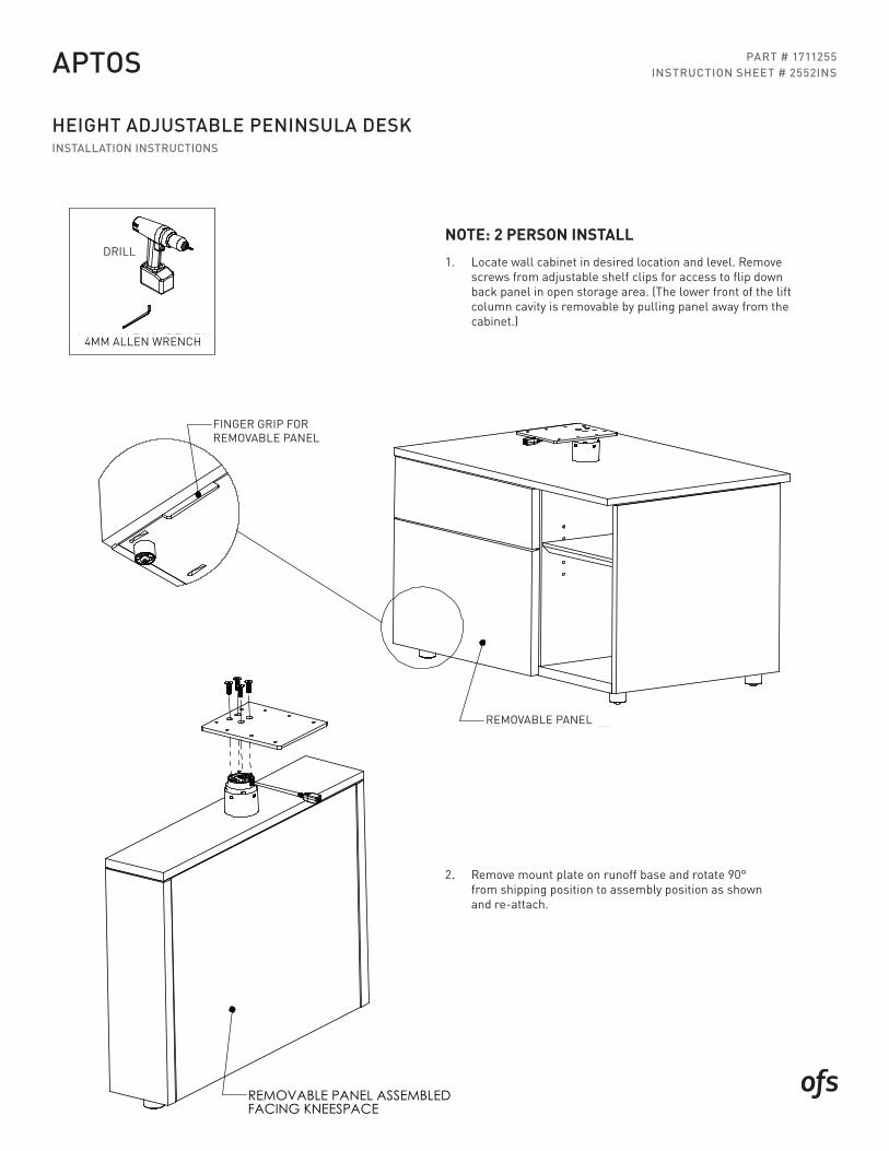
REMOVABLE PANEL
FINGER GRIP FOR REMOVABLE PANEL
NOTE: 2 PERSON INSTALL1. Locate wall cabinet in desired location and level. Remove
screws from adjustable shelf clips for access to flip down back panel in open storage area. (The lower front of the lift column cavity is removable by pulling panel away from the cabinet.)
2. Remove mount plate on runoff base and rotate 90° from shipping position to assembly position as shown and re-attach.
DRILL
4MM ALLEN WRENCH
INSTRUCTIONS
STEP 2B
STEP 2ASTEP 2C
STEP2: A. WITH WORK SURFACE UPSIDE DOWN ON A PROTECTIVE SURFACE INSTALL THE CONTROL BOX WITH HK-92 B. ATTACH THE CONTROL SWITCH WITH HK-83 (USE REMAINING SCREWS IN KIT TO SECURE WIRES AT THE END OF THE ASSEMBLY PROCESS) C. LOCATE RUNOFF BASE ASSEMBLY OVER PRE-BORED HOLE LOCATIONS IN TOP AND ATTACH USING HK-71(ONLY 4 HOLES WILL BE ACCESIBLE DURING THIS STEP).
2552INS - Page 2 Rev:
Part # - 2 Pages
STEP 3: A. FLIPOVER PREVIOUSLY ASSEMBLED TOP & RUNOFF BASE AND PLACE ON WALL CABINET MOUNTING PLATE AS SHOWN BELOW. (WILL NOT BE FASTENED UNTIL STEP 3 D). B. CONNECT RUNOFF BASE LIFT COLUMN WITH THE LONG CONTROL CABLE TO THE CONTROL BOX AND THE WALL CABINET LIFT COLUMN TO THE CONTROL BOX WITH SHORT CONTROL CABLE. THEN CONNECT THE CONTROL SWITCH TO THE CONTROL BOX. NEXT CONNECT THE MAINS (POWER) CABLE TO THE CONTROL BOX AND PLUG INTO A POWER SOURCE. C. SYNCRONIZE THE LIFT COLUMNS BY PRESSING THE DOWN ARROW BUTTON ON THE CONTROL SWITCH UNTIL THEY BOTTOM OUT. ONCE RESET PRESS THE UP ARROW BUTTON TO RAISE THE WORKSURFACE APPROX 10" TO ACCESS THE LIFT COLUMN MOUNTING PLATES. D. ONCE THE WORSURFACE IS RAISED FINISH INSTALLING THE REMAINING SCREWS FROM HK-71 ALIGNING THE HOLES IN THE MOUNT PLATES WITH PRE-BORED HOLESIN THE TOP. E. USE REMAINING SCREWS FROM HK-83 ALONG WITH WIRE CLIPS & ONE WRAPS TO CLEAN UP WIRES UNDERNEATH THE TOP AS DESIRED. F. USE THE DOWN ARROW BUTTON ON THE CONTROL SWITCH TO LOWER THE TOP BACK TO THE LOWEST POSITION AND LEVEL THE RUNOFF BASE AS NEEDED TO LEVEL THE WORKSURFACE.
PART # 1711255INSTRUCTION SHEET # 2552INS
HEIGHT ADJUSTABLE PENINSULA DESKINSTALLATION INSTRUCTIONS
APTOS
STEP 3
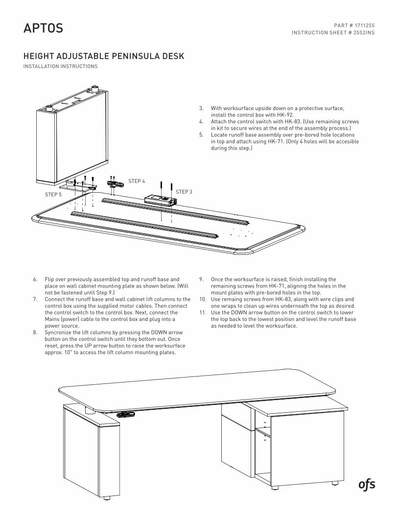
3. With worksurface upside down on a protective surface, install the control box with HK-92.
4. Attach the control switch with HK-83. (Use remaining screws in kit to secure wires at the end of the assembly process.)
5. Locate runoff base assembly over pre-bored hole locations in top and attach using HK-71. (Only 4 holes will be accesible during this step.)
STEP 4
STEP 5
9. Once the worksurface is raised, finish installing the remaining screws from HK-71, aligning the holes in the mount plates with pre-bored holes in the top.
10. Use remaing screws from HK-83, along with wire clips and one wraps to clean up wires underneath the top as desired.
11. Use the DOWN arrow button on the control switch to lower the top back to the lowest position and level the runoff base as needed to level the worksurface.
6. Flip over previously assembled top and runoff base and place on wall cabinet mounting plate as shown below. (Will not be fastened until Step 9.)
7. Connect the runoff base and wall cabinet lift columns to the control box using the supplied motor cables. Then connect the control switch to the control box. Next, connect the Mains (power) cable to the control box and plug into a power source.
8. Syncronize the lift columns by pressing the DOWN arrow button on the control switch until they bottom out. Once reset, press the UP arrow button to raise the worksurface approx. 10" to access the lift column mounting plates.
INSTRUCTIONS
WORK SURFACE INSTALLATION
LOW HEIGHT CABINET
WORK SURFACEHEIGHT CABINET
LOW HEIGHT CABINET
Place back panel against cabinets so vein lined edge is•against end panels. (Figure A)Use pry bar to lift back panel until it contacts work surface•
and is flush to the bottom of the end panels.When back panel is in place, secure by screwing #8 x 1/14" pan•head screws (HK-15) through pre-drilled holes in case spacers
fig. A
Pre-drilled holes Pre-drilled holes
Pre-drilled holes
1.25 1.25
VEINLINE
BACK PANEL INSTALLATION
Cabinets can be built either upright or upside-down.•Remove drawers and adjustable shelves from pedestals.•Lower fold-down backs in open pedestals.•Cabinets can be pilot bored and screwed together using•#8 x 1 1/4" pan head screws. (Note that this will defacethe outside of these cabinets).Place work surface on cabinets with 1.25" overhang to front•and back of SIDE PANEL.Attach work surface by screwing #8 x 1 1/4" pan head screws (HK-15)•through pre-drilled holes in case spacers or top panels.
WORK SURFACEHEIGHT CABINET
PRY BAR
Rev:Dwg: 2561INSINSTRUCTIONS
WORK SURFACE INSTALLATION
LOW HEIGHT CABINET
WORK SURFACEHEIGHT CABINET
LOW HEIGHT CABINET
Place back panel against cabinets so vein lined edge is•against end panels. (Figure A)Use pry bar to lift back panel until it contacts work surface•
and is flush to the bottom of the end panels.When back panel is in place, secure by screwing #8 x 1/14" pan•head screws (HK-15) through pre-drilled holes in case spacers
fig. A
Pre-drilled holes Pre-drilled holes
Pre-drilled holes
1.25 1.25
VEINLINE
BACK PANEL INSTALLATION
Cabinets can be built either upright or upside-down.•Remove drawers and adjustable shelves from pedestals.•Lower fold-down backs in open pedestals.•Cabinets can be pilot bored and screwed together using•#8 x 1 1/4" pan head screws. (Note that this will defacethe outside of these cabinets).Place work surface on cabinets with 1.25" overhang to front•and back of SIDE PANEL.Attach work surface by screwing #8 x 1 1/4" pan head screws (HK-15)•through pre-drilled holes in case spacers or top panels.
WORK SURFACEHEIGHT CABINET
PRY BAR
Rev:Dwg: 2561INS
INSTRUCTIONS
WORK SURFACE INSTALLATION
LOW HEIGHT CABINET
WORK SURFACEHEIGHT CABINET
LOW HEIGHT CABINET
Place back panel against cabinets so vein lined edge is•against end panels. (Figure A)Use pry bar to lift back panel until it contacts work surface•
and is flush to the bottom of the end panels.When back panel is in place, secure by screwing #8 x 1/14" pan•head screws (HK-15) through pre-drilled holes in case spacers
fig. A
Pre-drilled holes Pre-drilled holes
Pre-drilled holes
1.25 1.25
VEINLINE
BACK PANEL INSTALLATION
Cabinets can be built either upright or upside-down.•Remove drawers and adjustable shelves from pedestals.•Lower fold-down backs in open pedestals.•Cabinets can be pilot bored and screwed together using•#8 x 1 1/4" pan head screws. (Note that this will defacethe outside of these cabinets).Place work surface on cabinets with 1.25" overhang to front•and back of SIDE PANEL.Attach work surface by screwing #8 x 1 1/4" pan head screws (HK-15)•through pre-drilled holes in case spacers or top panels.
WORK SURFACEHEIGHT CABINET
PRY BAR
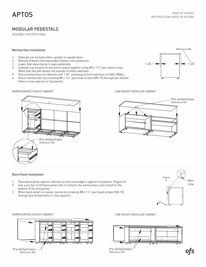
Rev:Dwg: 2561INS1. Cabinets can be built either upright or upside down.2. Remove drawers and adjustable shelves from pedestals.3. Lower fold-down backs in open pedestals.4. Cabinets can be pilot bored and screwed together using #8 x 11/4" pan head screws.
(Note that this will deface the outside of these cabinets).5. Place worksurface on cabinets with 1.25" overhang to front and back of SIDE PANEL.6. Attach worksurface by screwing #8 x 11/4" pan head screws (HK-15) through pre-drilled
holes in case spacers or top panels.
1. Place back panel against cabinets so vein lined edge is against end panels. (Figure A)2. Use a pry bar to lift back panel until it contacts the worksurface and is flush to the
bottom of the end panels.3. When back panel is in place, secure by screwing #8 x 11/4" pan head screws (HK-15)
through pre-drilled holes in case spacers.
MODULAR PEDESTALS ASSEMBLY INSTRUCTIONS
APTOS
Pre-drilled holes (Reference #6)
Worksurface Installation
Back Panel Installation
WORKSURFACE HEIGHT CABINETINSTRUCTIONS
WORK SURFACE INSTALLATION
LOW HEIGHT CABINET
WORK SURFACEHEIGHT CABINET
LOW HEIGHT CABINET
Place back panel against cabinets so vein lined edge is•against end panels. (Figure A)Use pry bar to lift back panel until it contacts work surface•
and is flush to the bottom of the end panels.When back panel is in place, secure by screwing #8 x 1/14" pan•head screws (HK-15) through pre-drilled holes in case spacers
fig. A
Pre-drilled holes Pre-drilled holes
Pre-drilled holes
1.25 1.25
VEINLINE
BACK PANEL INSTALLATION
Cabinets can be built either upright or upside-down.•Remove drawers and adjustable shelves from pedestals.•Lower fold-down backs in open pedestals.•Cabinets can be pilot bored and screwed together using•#8 x 1 1/4" pan head screws. (Note that this will defacethe outside of these cabinets).Place work surface on cabinets with 1.25" overhang to front•and back of SIDE PANEL.Attach work surface by screwing #8 x 1 1/4" pan head screws (HK-15)•through pre-drilled holes in case spacers or top panels.
WORK SURFACEHEIGHT CABINET
PRY BAR
Rev:Dwg: 2561INS
Pre-drilled holes (Reference #3)
WORKSURFACE HEIGHT CABINET
LOW HEIGHT MODULAR CABINET
LOW HEIGHT MODULAR CABINET
Pre-drilled holes (Reference #6)
Pre-drilled holes (Reference #3)
(Reference #5)
Figure A Vein
Line
PART # 1697863INSTRUCTION SHEET # 2561INS
INSTRUCTIONS
"Y"
30VERIFY BEFORE DRILLING
TAPE OFF AREATO BE DRILLED
STEP 2:CENTER PUNCH LOCATINGHOLES ON TEMPLATE
TEMPLATE
DETERMINE "Y" DIMENSION (CENTER OF PRIVACY PANEL) AND TAPE OFF AREA TO BE DRILLED TO 1.PROTECT FINISHED SURFACE.
LOCATE TEMPLATE IN DESIRED LOCATION USING CENTERLINES OF TEMPLATE AND CENTER PUNCH THE 2 2.LOCATING HOLES ON TEMPLATE.
REMOVE TEMPLATE AND VERIFY 30" CENTER TO CENTER BETWEEN LOCATING HOLE MARKS AND DRILL 2 3.HOLES 3/8 TO A DEPTH OF 5/8" AT PREVIOUSLY MARKED LOCATIONS, REMOVE TAPE AFTER DRILLING.
INSTALL (HK-118) MOUNTING PINS INTO 3/8 HOLES AND SECURE WITH SUPPLIED #10 X 1" SCREW (2 PER 4. PIN) LONG EDGE OF PLATE PARALLEL TO LENGTH OF PRIVACY SCREEN.
5. POSITION PRIVACY SCREEN ONTO MOUNTING PINS ALIGNING HOLES IN BOTTOM OF PRIVACY SCREEN AND SLIDE DOWN TO WORKSURFACE.
NOTE: IF UNIT WAS PRE-BORED AT THE FACTORY MOVE TO STEP 4
Rev: Dwg: 2548INS
PART # 1711253INSTRUCTION SHEET # 2548INS
SURFACE MOUNT PRIVACY SCREENSASSEMBLY INSTRUCTIONS
APTOS
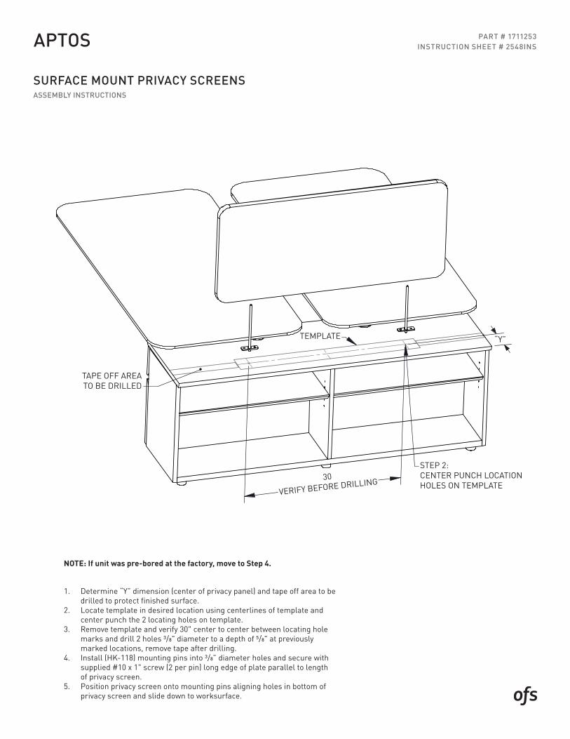
1. Determine “Y” dimension (center of privacy panel) and tape off area to be drilled to protect finished surface.
2. Locate template in desired location using centerlines of template and center punch the 2 locating holes on template.
3. Remove template and verify 30" center to center between locating hole marks and drill 2 holes 3/8" diameter to a depth of 5/8" at previously marked locations, remove tape after drilling.
4. Install (HK-118) mounting pins into 3/8” diameter holes and secure with supplied #10 x 1" screw (2 per pin) long edge of plate parallel to length of privacy screen.
5. Position privacy screen onto mounting pins aligning holes in bottom of privacy screen and slide down to worksurface.
NOTE: If unit was pre-bored at the factory, move to Step 4.
30
VERIFY BEFORE DRILLING
TEMPLATE
STEP 2:CENTER PUNCH LOCATION HOLES ON TEMPLATE
“Y”
TAPE OFF AREATO BE DRILLED
PART # 1698199INSTRUCTION SHEET # 2566INS
WALLMOUNT STORAGE & TACKBOARDINSTALLATION INSTRUCTIONS
CASEGOODS
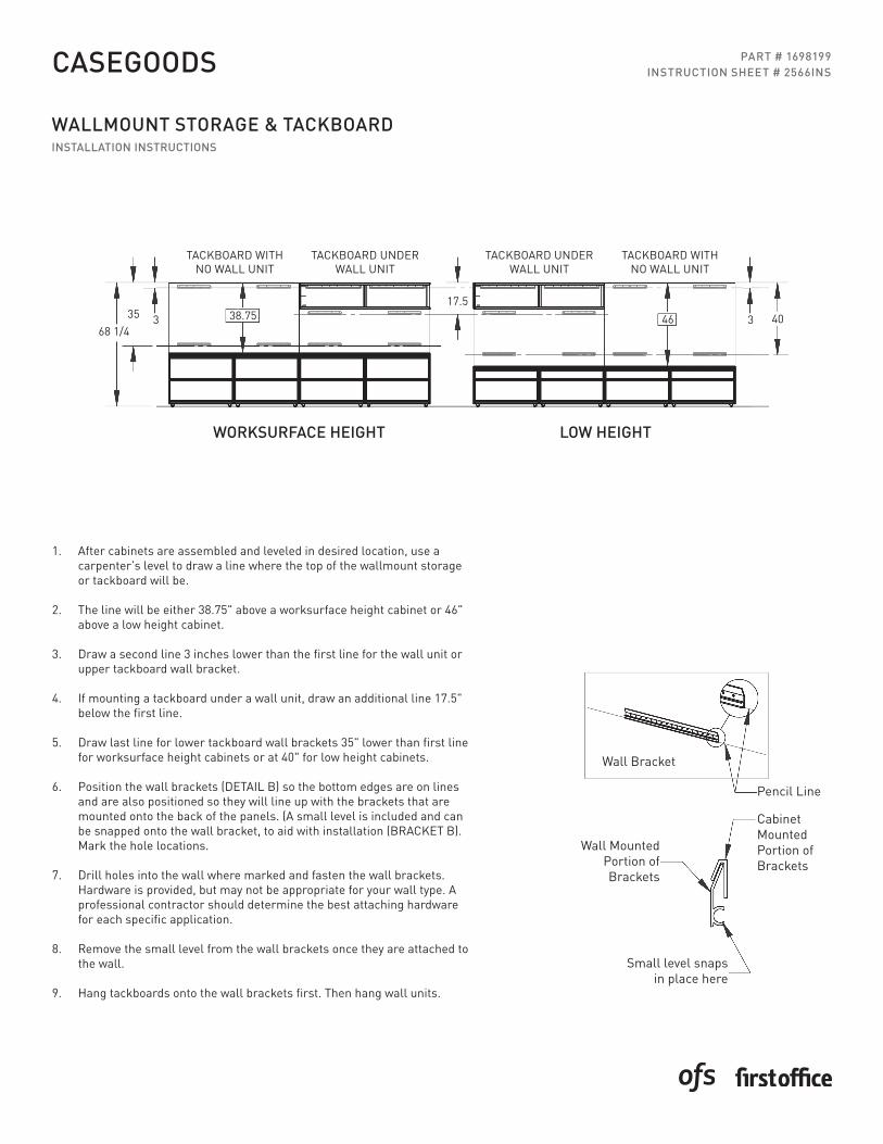
1. After cabinets are assembled and leveled in desired location, use a carpenter’s level to draw a line where the top of the wallmount storage or tackboard will be.
2. The line will be either 38.75" above a worksurface height cabinet or 46" above a low height cabinet.
3. Draw a second line 3 inches lower than the first line for the wall unit or upper tackboard wall bracket.
4. If mounting a tackboard under a wall unit, draw an additional line 17.5" below the first line.
5. Draw last line for lower tackboard wall brackets 35" lower than first line for worksurface height cabinets or at 40" for low height cabinets.
6. Position the wall brackets (DETAIL B) so the bottom edges are on lines and are also positioned so they will line up with the brackets that are mounted onto the back of the panels. (A small level is included and can be snapped onto the wall bracket, to aid with installation (BRACKET B). Mark the hole locations.
7. Drill holes into the wall where marked and fasten the wall brackets. Hardware is provided, but may not be appropriate for your wall type. A professional contractor should determine the best attaching hardware for each specific application.
8. Remove the small level from the wall brackets once they are attached to the wall.
9. Hang tackboards onto the wall brackets first. Then hang wall units.
Wall Bracket
Pencil Line
CabinetMountedPortion ofBrackets
Wall MountedPortion of Brackets
Small level snaps in place here
WORKSURFACE HEIGHT LOW HEIGHT
TACKBOARD WITH NO WALL UNIT
TACKBOARD WITH NO WALL UNIT
TACKBOARD UNDER WALL UNIT
TACKBOARD UNDER WALL UNIT
4068 1/4
34638.7533517.5
INSTRUCTIONS
ALIGN FLUSHTO BACK EDGE
Stack-EM-Pak
TWO-SIDED TAPE
Flush to bottomedge of top
WORK SURFACE STORAGE INSTALLATION
Position Stak-EM-Paks (HK-7) so they are parallel and inset from the• edge of the back panel by at least 1/4". The rounded edge of the Stak-EM-Pak should also be flush to the bottom edge of the top.
Mark hole locations and pre-drill 1/8" diameter x 1/4" deep pilot holes.•
Secure Stak-EM-Paks with #8 x 5/8" pan head screws. (HK-7)•
Peel off one side of backer on two-sided tape.•
Apply two-sided tape to bottom of cabinet.•
Peel off second backer.•
Position cabinet where desired, with back edge flush• to the edge of the top, and set in place.
Rev: Dwg: 2562INS
PART # 1699541INSTRUCTION SHEET # 2562INS
WORKSURFACE STORAGEINSTALLATION INSTRUCTIONS
APTOS
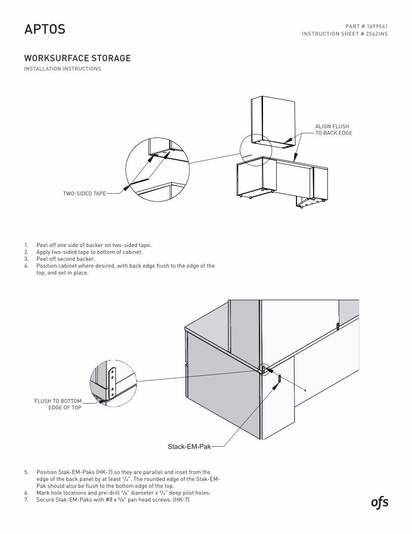
1. Peel off one side of backer on two-sided tape.2. Apply two-sided tape to bottom of cabinet.3. Peel off second backer.4. Position cabinet where desired, with back edge flush to the edge of the
top, and set in place.
5. Position Stak-EM-Paks (HK-7) so they are parallel and inset from the edge of the back panel by at least 1/4". The rounded edge of the Stak-EM-Pak should also be flush to the bottom edge of the top.
6. Mark hole locations and pre-drill 1/8" diameter x 1/4" deep pilot holes.7. Secure Stak-EM-Paks with #8 x 5/8" pan head screws. (HK-7)
TWO-SIDED TAPE
FLUSH TO BOTTOM EDGE OF TOP
ALIGN FLUSH TO BACK EDGE
PART # 1763420INSTRUCTION SHEET # 2583INS
EDGE MOUNT PRIVACY PANELSINSTALLATION INSTRUCTIONS
APTOS
INSTRUCTIONS
Dwg: Rev:2583INS Part # 1763420
1. Aligning the holes in the brackets with the pre-bored
screws in each bracket.
holes in the panel attach (3) mounting brackets to the privacy panel using (2) #8 x 1.5" pan head wood
Aptos - Edge Mount Privacy Panels
2. Leaving a 1.5" wire management gap between the worksurface edge and the face of the privacy panel, locate the privacy panel centered in the kneespace of the desk with the top of the mounting brackets flush to the underside of the work surface and attach the brackets to the work surface using (4) #8 x 1" pan head wood screws in each bracket.
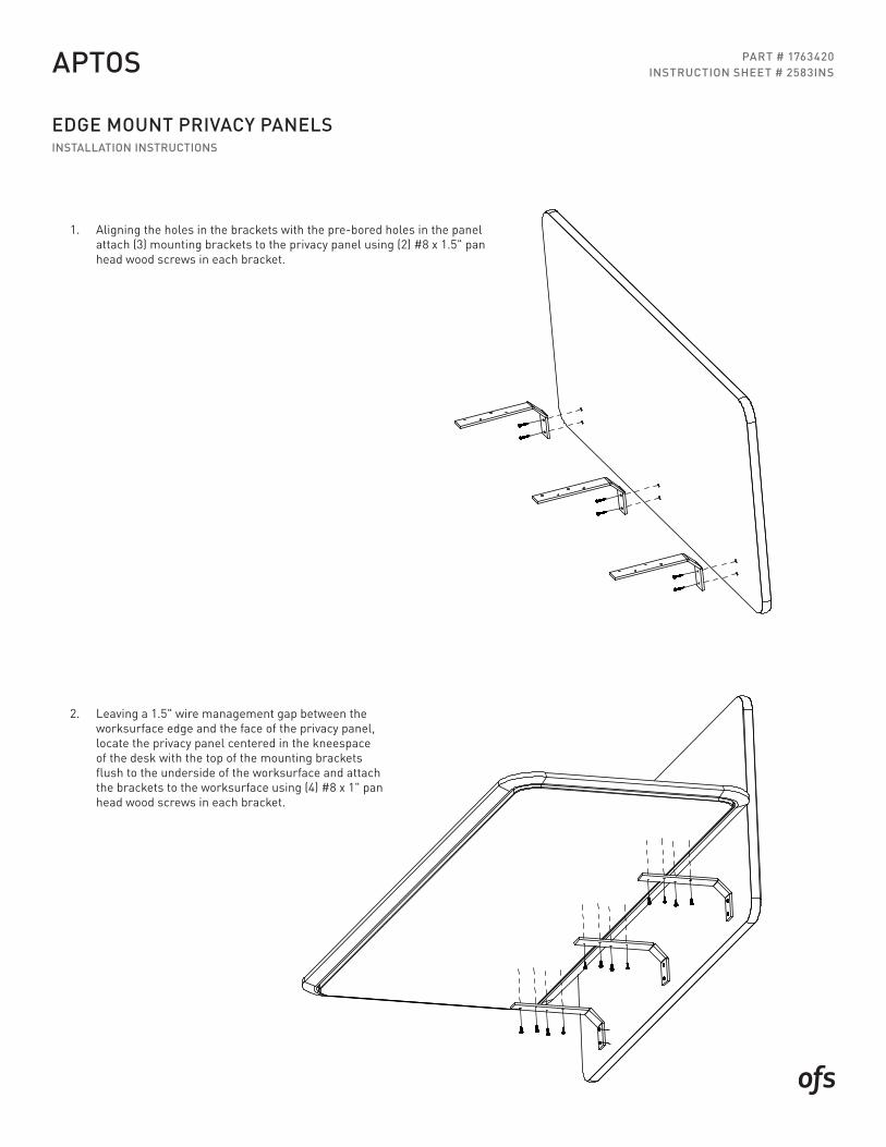
1. Aligning the holes in the brackets with the pre-bored holes in the panel attach (3) mounting brackets to the privacy panel using (2) #8 x 1.5" pan head wood screws in each bracket.
2. Leaving a 1.5" wire management gap between the worksurface edge and the face of the privacy panel, locate the privacy panel centered in the kneespace of the desk with the top of the mounting brackets flush to the underside of the worksurface and attach the brackets to the worksurface using (4) #8 x 1" pan head wood screws in each bracket.
INSTRUCTION SHEET # 2564INS
OPEN PLANINSTALLATION INSTRUCTIONS
APTOS
INSTRUCTIONS
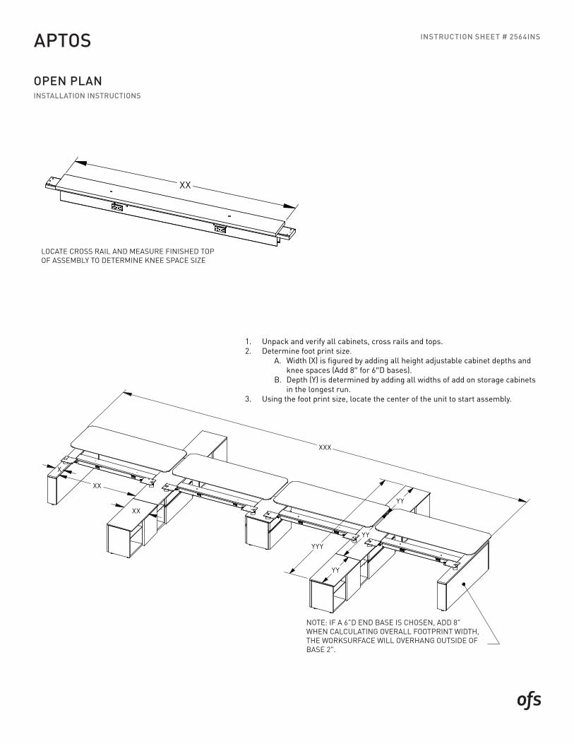
LOCATE CROSS RAIL & MEASURE FINISHED TOPOF ASSEMBLY TO DETERMINE KNEE SPACE SIZE
XX
2564INS - PAGE 1 Rev: _Dwg:
STEP 1: UNPACK AND VERIFY ALL CABINETS, CROSS RAILS, & TOPS.
STEP 2: DETERMINE FOOT PRINT SIZE.
A.WIDTH (X) IS FIGURED BY ADDING ALL HEIGHT ADJUSTABLE CABINET DEPTHS AND KNEE SPACES (ADD 8" FOR 6"D BASES.
B. DEPTH (Y) IS DETERMINED BY ADDING ALL WIDTHS OF ADD ON STORAGE CABINETS IN THE LONGEST RUN.
STEP 3: USING THE FOOT PRINT SIZE LOCATE THE CENTER OF THE UNIT TO START ASSEMBLY.
NOTE: IF A 6"D END BASE IS CHOSEN, ADD 8"WHEN CALCULATING OVERALL FOOTPRINTWIDTH, THE WORKSURFACE WILL OVERHANGOUTSIDE OF BASE 2".
YY
XX
X
XX
YY
YYY
YY
XXX
INSTRUCTIONS
LOCATE CROSS RAIL & MEASURE FINISHED TOPOF ASSEMBLY TO DETERMINE KNEE SPACE SIZE
XX
2564INS - PAGE 1 Rev: _Dwg:
STEP 1: UNPACK AND VERIFY ALL CABINETS, CROSS RAILS, & TOPS.
STEP 2: DETERMINE FOOT PRINT SIZE.
A.WIDTH (X) IS FIGURED BY ADDING ALL HEIGHT ADJUSTABLE CABINET DEPTHS AND KNEE SPACES (ADD 8" FOR 6"D BASES.
B. DEPTH (Y) IS DETERMINED BY ADDING ALL WIDTHS OF ADD ON STORAGE CABINETS IN THE LONGEST RUN.
STEP 3: USING THE FOOT PRINT SIZE LOCATE THE CENTER OF THE UNIT TO START ASSEMBLY.
NOTE: IF A 6"D END BASE IS CHOSEN, ADD 8"WHEN CALCULATING OVERALL FOOTPRINTWIDTH, THE WORKSURFACE WILL OVERHANGOUTSIDE OF BASE 2".
YY
XX
X
XX
YY
YYY
YY
XXX
LOCATE CROSS RAIL AND MEASURE FINISHED TOPOF ASSEMBLY TO DETERMINE KNEE SPACE SIZE
NOTE: IF A 6"D END BASE IS CHOSEN, ADD 8" WHEN CALCULATING OVERALL FOOTPRINT WIDTH, THE WORKSURFACE WILL OVERHANG OUTSIDE OF BASE 2".
1. Unpack and verify all cabinets, cross rails and tops.2. Determine foot print size.
A. Width (X) is figured by adding all height adjustable cabinet depths and knee spaces (Add 8" for 6"D bases). B. Depth (Y) is determined by adding all widths of add on storage cabinets in the longest run.
3. Using the foot print size, locate the center of the unit to start assembly.
INSTRUCTION SHEET # 2564INS
OPEN PLANINSTALLATION INSTRUCTIONS
APTOS
INSTRUCTIONS
Rev: _2564INS - PAGE 2Dwg:
BASES. CONNECT THE IN-FEED AND HAVE WIRED INTO FLOOR CORE.
STEP 9: IF APPLICABLE - TO INSTALL PRIVACY PANELS REFERENCE INSTRUCTION SHEET 2548INS (COMES WITH PRIVACY PANELS)
STEP 4: AFTER DETERMINING THE CENTER OF THE UNIT IN THE SPACE AVAILABLE PLACE THE HEIGHT ADJUSTABLE BASES TO MATCH THE CONFIGURATION OF THE SPEC DWG FOR THE SET UP. INSERTING THE CROSS RAILS INTO WIRE MANAGEMENT CUT OUTS ON THE SIDE OF THE HEIGHT ADJUSTABLE BASES. SECURINGTHEM AT A LATER TIME. (6"D BASES WILL NOT STAND ALONE UNTIL ATTACHED TO THE CROSS RAIL)
STEP 5: ROTATE THE WORKSURFACE MOUNTING PLATES FROM THE SHIPPING POSITION TO OVERHANGING THE KNEE SPACE AS SHOWN BELOW.
STEP 6: BEGIN LEVELING 2 OF THE BASES USING A LEVEL TO SPAN THE MOUNTING PLATES FRONT TO BACK AND ACROSS THE KNEESPACE TO THE NEXT BASE SIDE TO SIDE. UP TO 1" OF ADJUSTMENT IS AVAILABLE BY TURNING THE LEVELER FOOT OUT. ONCE THE BASES ARE LEVEL THE CROSS RAIL CAN BE ATTACHED. MARK THE CENTER OF THE TOP OF THE HEIGHT ADJUSTABLE BASES AND EACH END OF THE CROSS RAIL TOP FOR ALIGNMENT. REMOVE THE LOWER PANEL OF THE BASES( PULL TOWARDS KNEE SPACE) FOR ACCESS AND ATTACH CROSS RAIL USING A HK-15. PLACE A SQUARE ALONG THE EDGES OF THE CROSS RAIL TOP AND BASE TOP TO ENSURE SQUARENESS BEFORE SECURING.
STEP 7: REPEAT UNTIL ALL BASES ARE LEVEL AND CROSSRAILS ARE INSTALLED SQUARE.
STEP 8: CONNECT THE POWER JUMPER FROM ONE CROSS RAIL TO THE NEXT THROUGH THE WIRE MANAGEMENT CUT OUT IN THE HEIGHT ADJUSTABLE
NOTE: IT IS IMPORTANT THAT THE HEIGHT ADJUSTABLE BASES AND CROSS RAILS ARE INSTALLED LEVEL AND SQUARE TO AID IN THE REST OF THE ASSEMBLY PROCESS.
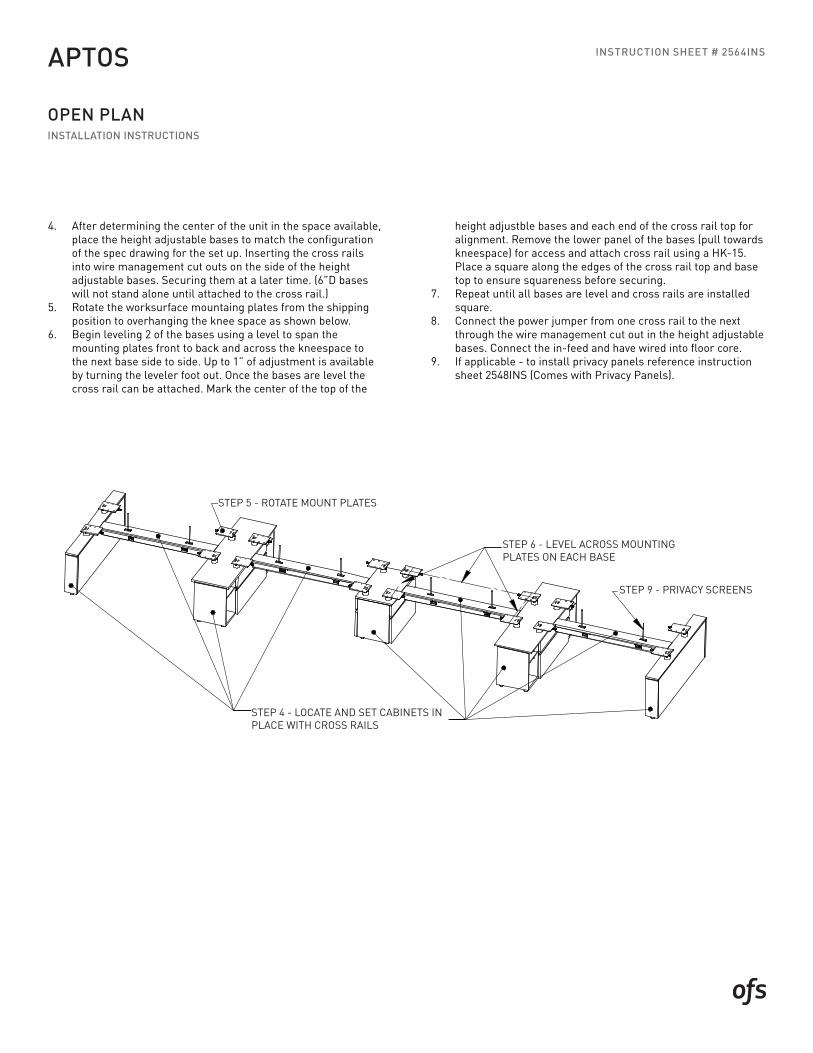
STEP 5 - ROTATE MOUNT PLATES
ON EACH BASESTEP 6 - LEVEL ACROSS MOUNTING PLATES
STEP 4 - LOCATE & SET CABINETS IN PLACE WITH CROSS RAILS
STEP 9 - PRIVACY SCREENS
STEP 4 - LOCATE AND SET CABINETS INPLACE WITH CROSS RAILS
STEP 5 - ROTATE MOUNT PLATES
STEP 6 - LEVEL ACROSS MOUNTING PLATES ON EACH BASE
STEP 9 - PRIVACY SCREENS
4. After determining the center of the unit in the space available, place the height adjustable bases to match the configuration of the spec drawing for the set up. Inserting the cross rails into wire management cut outs on the side of the height adjustable bases. Securing them at a later time. (6”D bases will not stand alone until attached to the cross rail.)
5. Rotate the worksurface mountaing plates from the shipping position to overhanging the knee space as shown below.
6. Begin leveling 2 of the bases using a level to span the mounting plates front to back and across the kneespace to the next base side to side. Up to 1” of adjustment is available by turning the leveler foot out. Once the bases are level the cross rail can be attached. Mark the center of the top of the
height adjustble bases and each end of the cross rail top for alignment. Remove the lower panel of the bases (pull towards kneespace) for access and attach cross rail using a HK-15. Place a square along the edges of the cross rail top and base top to ensure squareness before securing.
7. Repeat until all bases are level and cross rails are installed square.
8. Connect the power jumper from one cross rail to the next through the wire management cut out in the height adjustable bases. Connect the in-feed and have wired into floor core.
9. If applicable - to install privacy panels reference instruction sheet 2548INS (Comes with Privacy Panels).
INSTRUCTION SHEET # 2564INS
OPEN PLANINSTALLATION INSTRUCTIONS
APTOS
INSTRUCTIONS
_2564INS - PAGE 3 Rev:Dwg:
STEP 10: LOCATE AND PLACE SHARED STORAGE CABINETS. ALIGN AND LEVEL WITH PREVIOUSLY INSTALLED HEIGHT ADJUSTABLE BASES.
STEP 11: TEMPORARILY CONNECT CONTROL BOX TO THE LIFT COLUMNS WITH THE CONTROL CABLES, CONNECT CONTROL SWITCH TO THE CONTROL BOX & CONNECT THE MAINS (POWER) CABLE TO THE CONTROL BOX AND THEN PLUG INTO A POWER SOURCE.
STEP 12: PRESS THE DOWN ARROW BUTTON ON THE CONTROL SWITCH TO SYNCRONIZE THE LIFT COLUMNS. PRESS THE UP ARROW BUTTON ON ON THE CONTROL SWITCH TO RAISE THE LIFT COLUMNS, ALLOWING ACCESS FROM THE BOTTOM TO ATTACH THE WORK SURFACES.
STEP 13: PLACE A WORKSURFACE ON TWO LIFT COLUMNS SPANNING ACROSS A KNEE SPACE. WITH ONE PERSON SUPPORTING THE TOP AND A SECOND PERSON SECURING THE WORK SURFACE FROM UNDERNEATH USING A HK-71 ALIGNING THE HOLES IN THE MOUNT PLATES WITH THE PRE-BORED LOCATING HOLES IN THE BOTTOM OF THE SUB TOP. REPEAT FOR REMAINING TOPS.
STEP 14: MOUNT THE CONTROL BOX WITH HK-73 ALIGNING WITH THE 2 LOCATING HOLES IN THE BOTTOM OF THE WORK SURFACE AND THE CONTROL SWITCH USING HK-83 USING THE PRE-BORED LOCATING HOLES ON THE LEFT OR RIGHT SIDE OF THE USER EDGE OF THE WORKSURFACE.
STEP 15: USE THE REMAINING SCREWS FROM HK-83 ALONG WITH THE CORD CLIPS & ONE WRAP TO CLEAN UP AND SECURE WIRES UNDERNEATH THE WORK SURFACE AS DESIRED.
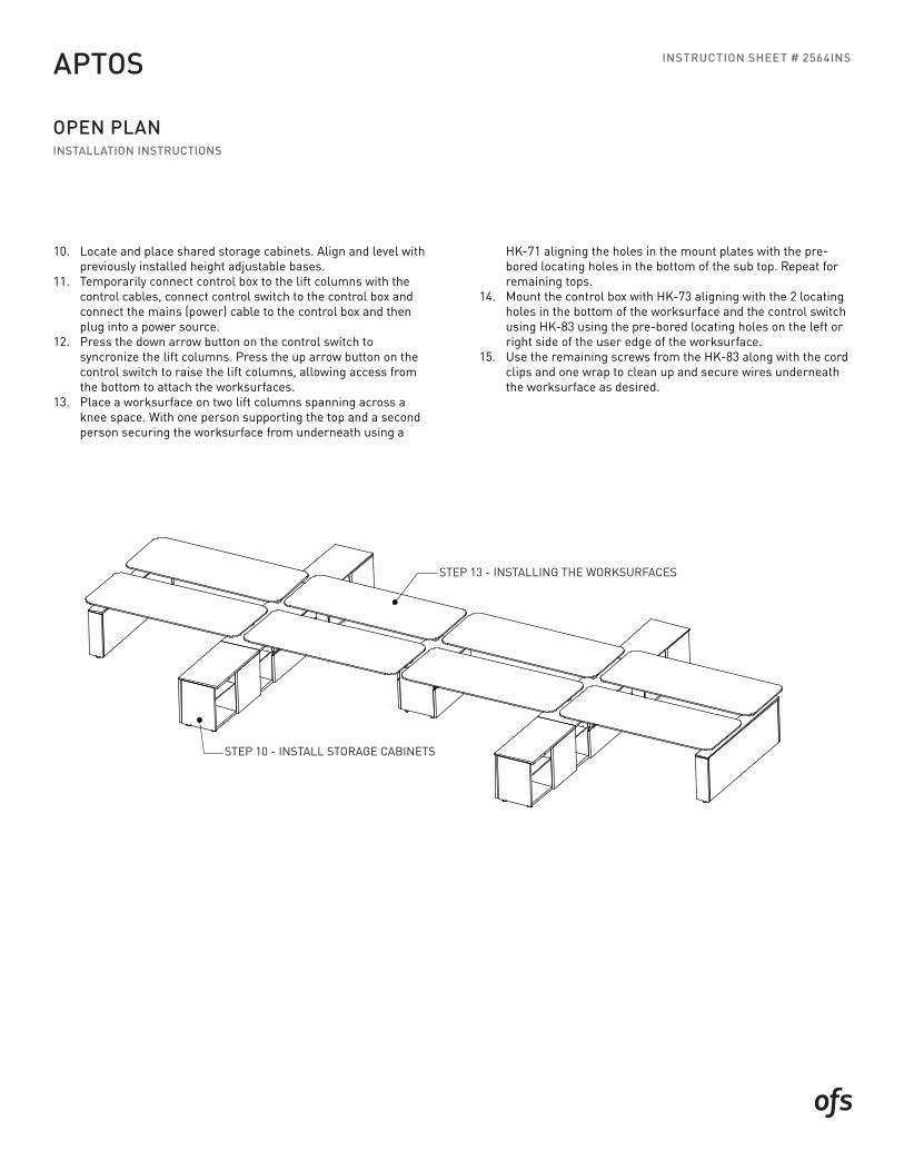
STEP 10 - INSTALL STORAGE CABINETS
STEP 13 - INSTALLING THE WORKSURFACES
STEP 10 - INSTALL STORAGE CABINETS
STEP 13 - INSTALLING THE WORKSURFACES
10. Locate and place shared storage cabinets. Align and level with previously installed height adjustable bases.
11. Temporarily connect control box to the lift columns with the control cables, connect control switch to the control box and connect the mains (power) cable to the control box and then plug into a power source.
12. Press the down arrow button on the control switch to syncronize the lift columns. Press the up arrow button on the control switch to raise the lift columns, allowing access from the bottom to attach the worksurfaces.
13. Place a worksurface on two lift columns spanning across a knee space. With one person supporting the top and a second person securing the worksurface from underneath using a
HK-71 aligning the holes in the mount plates with the pre-bored locating holes in the bottom of the sub top. Repeat for remaining tops.
14. Mount the control box with HK-73 aligning with the 2 locating holes in the bottom of the worksurface and the control switch using HK-83 using the pre-bored locating holes on the left or right side of the user edge of the worksurface.
15. Use the remaining screws from the HK-83 along with the cord clips and one wrap to clean up and secure wires underneath the worksurface as desired.