Embed Size (px)
Citation preview

Contact: NICT, Japan
Email:
APT/ITU Conformance and Interoperability Event 2015
7 – 8 September 2015, Bangkok, Thailand
Document C&I-3/INP-14 07 September 2015
NICT, Japan
WAVEFORM TRANSFER FOR SEAMLESS NETWORK SHOWCASING

1
Waveform transfer for seamless access communication systems
Tetsuya KAWANISHI
National Institute of Information and Communications Technology
Tokyo, Japan
This study was conducted as part of research projects “supported by the Japanese Government funding for “R&D to Expand Radio Frequency Resources” from the Ministry of Internal Affairs and Communications.
Outline
• Radio-over-fiber (RoF) for waveform transfer
• Concept of seamless links using RoF
• Possible applications– High resolution radars for FOD detection
– High speed wireless links of high-speed trains
• Field trial of FOD rader at CU Saraburi
C&I-3/INP-14
Page 1 of 17

2
Basic concept of Radio-on-fiber (RoF) system
RF signal is transmitted via optical fiber from central to antenna
RF signalsource
Electro-optic conversion
Photodetector
Central unit (CU) Remote antenna unit (RAU)/ Base station (BS)
Lightwave Modulated by RF signal
Optical fiber
Merit: Low loss connection, simple base station
RF signal RF signal
Recent Trends on RoF
• Application to 5G mobile fronthaul/backhaul
– Digital and/or analog
• High‐speed transmission at millimeter‐wave/terahertz wave
– Protection/temporal link in resilient network
C&I-3/INP-14
Page 2 of 17

3
Recent Trend of the session on OFC
MWP has a good presence in the communication conference
Bitrate and power consumption of wireless data transmitters
MBit/s nJ/Bit
Zigbee (TYP) 0.25 580
Bluetooth3.0+EDR (Planex) 2.1 170 Product BT-Micro3E2X
802.11b (TYP) 11 180
802.11b/g (iodata) 54 26 Product WN-G54/CB3L
UWBDice 10 3.2 R&D
802.11b/g/n (iodata) 300 4.3 Product WN-G300U
802.11b GainSpan (Alps) 11 36 Sample UGFZ1
WirelessHD SiBeam (Panasonic) 4000 2.5 Product TU-WH1
Optical transceiver 10GbE(SEI) 20000 0.05 Product SPP5000
T. Kawanishi, A. Kanno, T. Kuri and N. Yamamoto, "Transparent wave-form transfer for resilient and low-latency links," IEEE Photonics SocietyNewsletter, 28 (2014) 4
C&I-3/INP-14
Page 3 of 17

4
0.1 1 10 100 1000 10000
0.1
1
10
100
802.11b(GainSpan)
UWB WirelessHD802.11n
802.11g
Bluetooth
Po
we
r co
nsu
mp
tion
[nJ/
bit]
Bitrate [Mbps]
10GbE
Zigbee802.11b
y=248x-0.613
THz
Bitrate and power consumption of wireless data transmitters
T. Kawanishi, A. Kanno, T. Kuri and N. Yamamoto, "Transparent wave-form transfer for resilient and low-latency links," IEEE Photonics SocietyNewsletter, 28 (2014) 4
RoF for Next Mobile Services
TuB: RoF for Mobile Communication Systems will be held tomorrow.
4G(LTE/LTE‐A) mobile fronthaul technology such as CPRI, OBSAI and ORI is based on digitized RoF.
For Next‐Gen. 5G?, we have to discuss in the MWP.
From G.‐K. Chang, et el., IEEE ICC'13 WS Optical‐Wireless
C&I-3/INP-14
Page 4 of 17

5
Wideband wireless and high-speed transmission
Combination of optical digital links and radio transmitters
APT REPORT ON WIRED AND WIRELESS SEAMLESS CONNECTIONS USING MILLIMETER-WAVE RADIO ON FIBER TECHNOLOGY FOR RESILIENT ACCESS NETWORKS
C&I-3/INP-14
Page 5 of 17

6
RoF
O/E
OpticalRo
F E
/O
Ser
.
DS
P
Data
Digital coherent optical transmission
De
s.
DS
P
E/O
RoF Tx.Optical Tx.
High-speed and precise lightwave control and detection (Vector E/O and O/E)
Optical Rx.
Data
High-performance digital signal processing (DSP) at Tx. and / or Rx.
Combination of DSP and vector lightwave control can generate high‐frequency broadband wireless signals.
Expansion of optical connection by high-speed wireless based on Radio-
over-Fiber
RoF
O/E
OpticalRo
F E
/O
Ser
.
DS
P
Data
De
s.
DS
P
E/O
RoF
E/O
Optical
High-speed millimeter-wave radio
Ro
F E
/O
De
s.
DS
P
Data Ser
.
DS
P
O/E
Optical Tx.
Optical Rx.
Media conv.RAU
Media conv.RAU
C&I-3/INP-14
Page 6 of 17

7
Seamless optical/radio link
RF signal over fiber
Wideband IF signal over fiber
APT REPORT ON WIRED AND WIRELESS SEAMLESS CONNECTIONS USING MILLIMETER-WAVE RADIO ON FIBER TECHNOLOGY FOR RESILIENT ACCESS NETWORKS
Spectral efficiency in optical domain can be large. IF can be zero. (M2D.3)
Concept of wired and wireless seamless transmission for resilient network
Agile deployment capability for• Protection link against fiber being cut at disaster• Temporal link to temporary station at disaster recovery• “Last mile” solution until optical fiber deployment
×
High-speed radio (> 10 Gbps)
Optical fiber
Temporary station
Radio Access Unit(RAU)
(> 100 Gbps)
C&I-3/INP-14
Page 7 of 17

8
MIMO: to Enhance Total CapacityConventional
RAU
Optical Tx O/E
DS
P
Digital DP sig.
Des
.
Rad
io F
E
Digitalradio Rx
High power consumptionLarge latency
Coherent MIMO RoF system
• “Radio-friendly” optical signal by RoF Tx• Polarization diversity O/E derivers MIMO radio signal directly.
RoF Tx
Optical digi.-coh.-
basedradio RxP
ol.-
div.
O
/E
DP-RoF signalR
adio
FE
A. Kanno, Opt. Express, 20, 29395 (2012).
Coherent two-tone generation: See a. Kanno, IPC11, TuJ4 (2011)
Optical‐PDM/RF‐MIMO transmission setup
Pol.-diversity OE convertersOptical DP-QPSK-detector-based digital coherent Rx.
A. Kanno, ECOC2012, We.3.B.2 (2012).
C&I-3/INP-14
Page 8 of 17

9
Observed BERs (74.4 Gb/s in 20 Gbaud)A. Kanno, Opt. Express, 20, 29395 (2012).
High‐speed 60‐GHz Trans.
M. Weiss et al., MWP 2009, Valencia, Spain, 2009, (post deadline paper)
C.‐T. Lin et al., OFC2014, M3D.1 (2014).
5 years
MWP plays a role as advanced technology testbed of future wireless communication.
27 Gbit/sat 60 GHz
84 Gbit/sby 2x2 MIMOat 60 GHz
C&I-3/INP-14
Page 9 of 17

10
Millimeter‐wave Trans at >60 GHz
• W‐band, 120 GHz, 220 GHz,…
100‐Gb/s capability at W‐band 400‐Gb/s demonstration at W‐band
J. Yu et al., ECOC2014, We3.6.6D. Zibar et al., MWP/APMP2011
100‐Gb/s demo at 220 GHz
4 yrs.
4x4 MIMO 28Gbd 16‐QAMSingle‐channel OFDM
S. Koenig et al., Nature Photonics 7, 977 (2013)
Doubled freq.
Highly-precise Optical Clock Signal Gen.
Electrode A
Signal + Bias
Bias
Bias
Optical
input
Optical
output
Electrode B
Electrode C
MZa
MZb
Pure two‐tone source
1549.6 1549.8 1550.0 1550.2 1550.4
-80
-70
-60
-50
-40
-30
-20
-10Desiredcomponents
49.0dB
Op
tica
l po
we
r [d
Bm
]
Wavelength [nm]
46.6dB
T. Kawanishi et al., CLEO/QELS 2008, CFA1
High‐ER modulatorDistribution of stable LO signal (31‐120 GHz) over fibers
OE conversion OE conversion OE conversion OE conversion
ALMA: Atacama Large Millimeter/sub-millimeter Array
The site is at height of 5000m above sea level. The longest baseline is 14km and the resolution is 0.001 arcsecwhich is better than the Hubble space telescope. Receiving frequency: 31-950 GHz.
ALMA Photonic LO System by NAOJ, NICT
C&I-3/INP-14
Page 10 of 17

11
High-Speed Photodiodes• Zero-biased ultra-high-speed photodiodes beyond 110
GHz.
‐10
‐8
‐6
‐4
‐2
0
2
4
0 20 40 60 80 100 120
Relative gain (dB)
Frequency (GHz)
‐50
‐40
‐30
‐20
‐10
0
‐5
‐4
‐3
‐2
‐1
0
0 20 40 60 80 100 120
S21, S11 (dB)
Frequency (GHz)Package photo with 1mm connector
Fabricated unitraveling-carrer photodiode Frequency response of photodiodes3dB Bandwidth > 110 GHz with bias=0
S-parameter measurement of packaged PD
HITACHI, NICT, ENRI, RTRI 2015. All rights reserved.
Frequency Response Analyzer
Frequency Response Analyzer
RF Signal Generator Control PC
RF Power Meter
PD under Test
Optical Power Meter
Two-tone lightwaveas a standard Signal
Output PureRF signal
Frequency range:
0.1〜40GHz
Measurement time:< 2 sec Accuracy: <0.1dB
K. Inagaki, et al., IEICE Electronics Express, Vol. 9, 220 (2012)
APT Report on Characteristics and Requirements of Optical and Electric Components for Millimeter-wave Radio on Fiber systems ASTAP/REPT 3
C&I-3/INP-14
Page 11 of 17

12
High-Capacity MMW-RoF Backhaul for Railways
WDM-RoF NetworkWSS-based WDM routing
Central officeSignal generation and location detection
Adaptive routing for signal delivery to suitable sites.
Activate radio head
High-speed signal transport and adaptive routing with tracking the location of the trains.
1–10-Gb/s signal transport to high-speed trains
Millimeter-wave high-capacity radio (>1 Gb/s)
• Radio-over-Fiber (RoF)-based signal transport
• High-speed O/E and E/O devices• Flexible/high-speed WSS
This study was conducted as part of the research project “R&D of high-precision imaging technology using 90 GHz band linear cells,” supported by the Japanese Government funding for “R&D to Expand Radio Frequency Resources” from the Ministry of Internal Affairs and Communications.
R&D of high-precision imaging technology using 90 GHz band linear cells
C&I-3/INP-14
Page 12 of 17
13
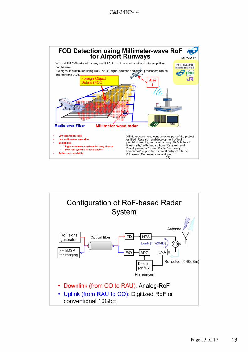
Millimeter wave radarRadio-over-Fiber
Foreign Object Debris (FOD)
Alert
W-band FM-CW radar with many small RAUs. => Low-cost semiconductor amplifiers can be used.FM signal is distributed using RoF. => RF signal sources and signal processors can be shared with RAUs.
FOD Detection using Millimeter-wave RoFfor Airport Runways
※This research was conducted as part of the project entitled “Research and development of high-precision imaging technology using 90 GHz band linear cells,” with funding from “Research and Development to Expand Radio Frequency Resources” supported by the Ministry of Internal Affairs and Communications, Japan.
MIC-PJ※
25
• Low operation cost
• Low radio-wave emission
• Scalability: • High-performance systems for busy airports
• Low-cost systems for local airports
• Agile scan capability
Configuration of RoF-based Radar System
• Downlink (from CO to RAU): Analog-RoF
• Uplink (from RAU to CO): Digitized RoF or conventional 10GbE
RoF signalgenerator
PD HPA
Diode(or Mix)
LNAADCFFT/DSPfor imaging
E/O
Leak (~ -20dB)
Heterodyne
Optical fiber
Antenna
Reflected (<-40dBm)
C&I-3/INP-14
Page 13 of 17

14
HITACHI, NICT, ENRI, RTRI 2015. All rights reserved.
CU,NiCT,ENRI and Hitachi Ltd.
2015 July @Churalonkong University Saraburi Campus
FOD Experiment @CU Saraburi
HITACHI, NICT, ENRI, RTRI 2015. All rights reserved.
Site overview
C&I-3/INP-14
Page 14 of 17

15
HITACHI, NICT, ENRI, RTRI 2015. All rights reserved.
Range Resolution
29
8cm
Imaging by using two radar units130m(+5dBsm)
C&I-3/INP-14
Page 15 of 17

16
Preliminary data from two radar units
130m133m 127m
1m
-1m
-3m
130m x sin 0.8deg = 1.8mRange resolution 1.8cmAngular resolution 0.8deg
Preliminary data from two radar units
130m x sin 0.8deg = 1.8mRange resolution 1.8cmAngular resolution 0.8deg
1.2mGeometric mean of two images
C&I-3/INP-14
Page 16 of 17

17
Issues
• Interfaces between RoF and digital networks
• RoF network archtechture
• Control of cells and networks
• Requirements on RoF links
• Measurement techniques for RoF components– APT Report on Characteristics and Requirements of Optical and
Electric Components for Millimeter-wave Radio on Fiber systems ASTAP/REPT 3
C&I-3/INP-14
Page 17 of 17