Embed Size (px)
Citation preview

Request for Proposal[insert date]
[insert Proposal number]
American Public Transportation Association1666 K Street, NW, Washington, DC, 20006-1215
published: October, 2010
Standard Bus Procurement Guidelines RFP
Abstract: This document outlines a request for proposals for a negotiated bus procurement contract. A request for proposals is generally used when the scope of Work or specification is less well-defined. In addition, this type of procurement may be used in cases where the vehicle involves “emerging” technology or there is a requirement to discuss warranty provisions or design considerations. This document was developed using a cross-section of representatives from the public and private sectors of the public transit industry for use by transit agencies.
Keywords: bus, request for proposals (RFP)
Overview: Many industries have standard forms of contracts for the acquisition of goods and services. Buyers and sellers in those industries become familiar and comfortable with those forms. The goal of creating a common method of contracting enables participants to focus, when necessary, on negotiating only those issues for which a departure from the accepted norm is necessary or desirable. This approach will save considerable time and effort for the parties to a particular transaction. It also permits new provisions or evolving best practices to be incorporated into the standard Contract for that industry efficiently and in a manner designed to benefit the entire industry. Finally, standardization leads to a consistency of interpretation that presumably should reduce the number of Contract disputes and result in better prices for both the public and private sectors.
© 2010 American Public Transportation Association. No part of this publication may be reproduced in any form, in an electronic retrieval system or otherwise, without the prior written permission of the American Public Transportation Association.
How This Document is OrganizedThe outline has been created to facilitate the development of a bus package that is consistent throughout the industry, providing a uniform format for numbering and organizing such documents. The use of standard formats for commonly used procurement contracts will improve the ability of industry participants to prepare contracts that contain all necessary provisions and that facilitate the incorporation of best available practices.
The format for a bus Contract RFP is organized as follows:
• The Notice of Request for Proposals (RFP) (Section 1) contains general information to prospective proposers regarding the RFP package and can also be used as notification of the RFP to the public or an advertisement of the procurement opportunity.
• The Instructions to Proposers (Section 2) provides detailed requirements that proposers must follow in submitting their Proposal. This section also includes evaluation criteria and information of interest to the Proposer regarding Agency Contract award procedures.
• The General Conditions (Section 3), once customized by each Agency, should contain the standard terms and conditions and should be modified only by language added in the Special Provisions section.
• The Special Provisions (Section 4) should be customized to meet the Agency’s specific requirements for each individual project or Contract, as well as local and state requirements. The Special Provisions are intended to amend and supplement the General Conditions to meet the individual requirements of each project.
• The Federal Requirements (Section 5) are detailed and should be removed when the project is not funded with federal funds.
• The Technical Specifications (Section 6) are included and can be detached as a standalone document.
• The Warranty Requirements (Section 7) include requirements to warrant the operation of the bus.• Quality Assurance (Section 8) covers manufacturing, inspection and acceptance procedures.• Forms and Certifications (Section 9) are submitted with the Proposal or the Proposal may be
considered nonresponsive.• Contract (Section 10) will incorporate the surviving terms of the RFP, as well as the Contractor’s
Proposal in a binding document to be executed by the Agency and successful Proposer within a designated time period following award. It should be inserted as Section 10.
• Appendixes (Section 11).
It is understood that transit agencies will need to modify this document to reflect local and state rules, regulations and laws, and that they will insert the standard contract language that they have developed in the appropriate places in the document. However, modifications to the standard format should be made in a manner that will maintain the structural integrity of the document. The numbering of unused articles should be maintained and accompanied by the notations “not used” or “reserved.”
© 2010 American Public Transportation Association. No part of this publication may be reproduced in any form, in an electronic retrieval system or otherwise, without the prior written permission of the American Public Transportation Association.
How to Use This DocumentThis document has been designed to be a “living” document and will be reviewed bi-annually to stay current with new or updated regulations, policies and technologies.
Items noted in brackets [example] are areas indicating Agency input and should be filled in accordingly. As this is living document, references to other sections in the document are noted by title only. All section titles are listed in the Table of Contents.
The Technical Specifications section is designed for multiple bus lengths and propulsion types. By selecting “Default,” a basic bus technical specification will be developed. In areas where there are alternatives to the default, the Agency may select “Alternative” instead.
NOTE: Selection of certain alternatives may present a conflict with other selections and should be carefully considered.
© 2010 American Public Transportation Association. No part of this publication may be reproduced in any form, in an electronic retrieval system or otherwise, without the prior written permission of the American Public Transportation Association.

Request for Proposal[insert date]
[insert Proposal number]
Request for Proposal
[Insert Agency name and logo]
[Insert Proposal number]
[Insert month date, year]
1
Contents
SECTION 1: NOTICE OF REQUEST FOR PROPOSALS...........................................................................................13NR 1. Description of the Work to be Done..................................................................................................13NR 2. Obtaining Proposal Documents.........................................................................................................13NR 3. Proposal Due Date and Submittal Requirements..............................................................................13NR 4. Validity of Proposals.........................................................................................................................13NR 5. Pre-Proposal Meeting Information [Optional]..................................................................................13
SECTION 2: INSTRUCTIONS TO PROPOSERS.........................................................................................................15IP 1. Quantities.............................................................................................................................................15IP 2. Proposed Schedule for the Procurement..............................................................................................15IP 3. Obtaining Proposal Documents...........................................................................................................15IP 4. Proposal Security Requirements (Reserved).......................................................................................15IP 5. Pre-Proposal Meeting/Information for Proposers...............................................................................15IP 6. Questions, Clarifications and Omissions.............................................................................................16IP 7. Addenda to RFP..................................................................................................................................16IP 8. DBE Requirements for Transit Vehicle Manufacturers......................................................................17IP 9. Buy America Certification..................................................................................................................17IP 10. Conditions, Exceptions, Reservations or Understandings.................................................................18IP 11. Protest Procedures.............................................................................................................................18
IP 11.1 Address.....................................................................................................................................18IP 11.2 Pre-Proposal Protests................................................................................................................19IP 11.3 Protests on the Recommended Award......................................................................................19IP 11.4 FTA Review..............................................................................................................................19
IP 12. Preparation of Proposals....................................................................................................................19IP 12.1 Use of Proposal Forms..............................................................................................................19IP 12.2 Alternate and Multiple Proposals (Reserved)...........................................................................19IP 12.3 Proposal Format Requirements.................................................................................................19IP 12.4 Agency Treatment of Proprietary/Confidential Information....................................................21IP 12.5 Signing of Proposal Forms........................................................................................................22IP 12.6 Modification or Withdrawal of Proposals.................................................................................22IP 12.7 Ownership and Cost of Proposal Development........................................................................23
IP 13. Proposal Evaluation, Negotiation and Selection...............................................................................23IP 13.1 Confidentiality of Proposals.....................................................................................................23IP 13.2 Duration of the Validity of Proposals.......................................................................................23IP 13.3 Evaluation Committee..............................................................................................................23IP 13.4 Review of Proposals for Responsiveness and Proposers for Responsibility............................24IP 13.5 Proposal Selection Process.......................................................................................................24IP 13.6 Evaluation Procedures..............................................................................................................26IP 13.7 Evaluations of Competitive Proposals......................................................................................26
IP 14. Response to Proposals.......................................................................................................................28IP 14.1 Single Proposal Response.........................................................................................................28IP 14.2 Availability of Funds................................................................................................................28IP 14.3 Agency Contract Approval Process..........................................................................................28IP 14.4 Agency Rights...........................................................................................................................28IP 14.5 Execution of Contract...............................................................................................................29
IP 15. Conflicts of Interests and Gratuities..................................................................................................29IP 16. Agency-Specific Provisions..............................................................................................................29
2

SECTION 3: GENERAL CONDITIONS........................................................................................................................30GC 1. Definitions.........................................................................................................................................30GC 2. Materials and Workmanship..............................................................................................................31GC 3. Conformance with Specifications and Drawings..............................................................................31GC 4. Inspection, Testing and Acceptance..................................................................................................32
GC 4.1 General......................................................................................................................................32GC 4.2 Risk of Loss..............................................................................................................................32
GC 5. Title and Warranty of Title................................................................................................................32GC 6. Intellectual Property Warranty..........................................................................................................32GC 7. Data Rights........................................................................................................................................33
GC 7.1 Proprietary Rights/Rights in Data.............................................................................................33GC 7.2 Access to Onboard Operational Data........................................................................................33
GC 8. Changes.............................................................................................................................................33GC 8.1 Contractor Changes...................................................................................................................33GC 8.2 Agency Changes.......................................................................................................................34
GC 9. Legal Clauses.....................................................................................................................................34GC 9.1 Indemnification.........................................................................................................................34GC 9.2 Suspension of Work..................................................................................................................35GC 9.3 Excusable Delays/Force Majeure.............................................................................................35GC 9.4 Termination...............................................................................................................................36GC 9.5 Compliance with Laws and Regulations...................................................................................38GC 9.6 Changes of Law........................................................................................................................38GC 9.7 Governing Law and Choice of Forum......................................................................................38GC 9.8 Disputes.....................................................................................................................................38GC 9.9 Maintenance of Records; Access by Agency; Right to Audit Records....................................40GC 9.10 Confidential Information........................................................................................................41GC 9.11 Conflicts of Interest, Gratuities...............................................................................................42GC 9.12 General Nondiscrimination Clause.........................................................................................42GC 9.13 Amendment and Waiver.........................................................................................................42GC 9.14 Remedies not Exclusive..........................................................................................................42GC 9.15 Counterparts............................................................................................................................43GC 9.16 Severability.............................................................................................................................43GC 9.17 Third-Party Beneficiaries........................................................................................................43GC 9.18 Assignment of Contract..........................................................................................................43GC 9.19 Independent Parties.................................................................................................................43GC 9.20 Survival...................................................................................................................................43
GC 10. Agency-Specific Provisions............................................................................................................43
SECTION 4: SPECIAL PROVISIONS..........................................................................................................................44SP 1. Inspection, Tests and Repairs.............................................................................................................44
SP 1.1 Pilot Bus.....................................................................................................................................44SP 1.2 Configuration and Performance Approval.................................................................................44SP 1.3 First Article Inspection – Production.........................................................................................44SP 1.4 Post-Delivery Tests....................................................................................................................45SP 1.5 Repairs after Non-Acceptance...................................................................................................45SP 1.6 Repair Performance....................................................................................................................45
SP 2. Deliveries............................................................................................................................................46SP 2.1 Bus Delivery..............................................................................................................................46SP 2.2 Delivery Schedule......................................................................................................................46SP 2.3 Contract Deliverables.................................................................................................................46
SP 3. Options and Option Pricing................................................................................................................49
3

SP 4. Assignability of Options.....................................................................................................................50SP 5. Payment..............................................................................................................................................50
SP 5.1 Payment Terms..........................................................................................................................50SP 5.2 Performance Guarantee (Optional)............................................................................................53SP 5.3 Payment of Taxes.......................................................................................................................53
SP 6. Liquidated Damages for Late Delivery of the Bus.............................................................................53SP 7. Service and Parts................................................................................................................................54
SP 7.1 Contractor Service and Parts Support........................................................................................54SP 7.2 Documentation...........................................................................................................................54SP 7.3 Parts Availability Guarantee......................................................................................................55SP 7.4 Agency-Furnished Property.......................................................................................................55
SP 8. Federal Motor Vehicle Safety Standards (FMVSS)...........................................................................55SP 9. Insurance.............................................................................................................................................56SP 10. Software Escrow Account................................................................................................................56SP 11. Sustainability....................................................................................................................................57SP 12. Agency-Specific Provisions.............................................................................................................57
SECTION 5: FEDERAL REQUIREMENTS..................................................................................................................58FR 1. Access to Records..............................................................................................................................58
FR 1.1 Local Governments....................................................................................................................58FR 1.2 State Governments.....................................................................................................................58
FR 2. Federal Funding, Incorporation of FTA Terms and Federal Changes...............................................58FR 3. Federal Energy Conservation Requirements......................................................................................59FR 4. Civil Rights Requirements.................................................................................................................59FR 5. No Government Obligation to Third Parties......................................................................................60FR 6. Program Fraud and False or Fraudulent Statements or Related Acts................................................60FR 7. Suspension and Debarment................................................................................................................60FR 8. Disadvantaged Business Enterprise (DBE)........................................................................................61FR 9. Clean Water Requirements................................................................................................................61FR 10. Clean Air Requirements...................................................................................................................61FR 11. Compliance with Federal Lobbying Policy......................................................................................62FR 12. Buy America....................................................................................................................................62FR 13. Testing of New Bus Models.............................................................................................................62FR 14. Pre-Award and Post-Delivery Audits...............................................................................................63FR 15. Cargo Preference..............................................................................................................................63FR 16. Fly America......................................................................................................................................63FR 17. Contract Work Hours and Safety Standards Act..............................................................................64
SECTION 6: TECHNICAL SPECIFICATIONS.............................................................................................................65TS 1. Scope..................................................................................................................................................65TS 2. Definitions..........................................................................................................................................65TS 3. Referenced Publications.....................................................................................................................71TS 4. Legal Requirements............................................................................................................................71TS 5. Overall Requirements.........................................................................................................................71
TS 5.1 Weight........................................................................................................................................71TS 5.2 Capacity.....................................................................................................................................71TS 5.3 Service Life................................................................................................................................71TS 5.4 Maintenance and Inspection......................................................................................................71TS 5.5 Interchangeability......................................................................................................................72TS 5.6 Training......................................................................................................................................72TS 5.7 Operating Environment..............................................................................................................73
4

TS 5.8 Noise..........................................................................................................................................73TS 5.9 Fire Safety..................................................................................................................................74TS 5.10 Respect for the Environment...................................................................................................74
TS 6. Physical Size.......................................................................................................................................75TS 6.1 Bus Length.................................................................................................................................75TS 6.2 Bus Width..................................................................................................................................76TS 6.3 Bus Height.................................................................................................................................76TS 6.4 Step Height................................................................................................................................76TS 6.5 Underbody Clearance................................................................................................................76TS 6.6 Ramp Clearances.......................................................................................................................76TS 6.7 Ground Clearance......................................................................................................................77TS 6.8 Floor Height...............................................................................................................................78TS 6.9 Interior Headroom......................................................................................................................78TS 6.10 Aisle Width..............................................................................................................................79
TS 7. Power Requirements...........................................................................................................................79TS 7.1 Top Speed..................................................................................................................................79TS 7.2 Gradability.................................................................................................................................79TS 7.3 Acceleration...............................................................................................................................79TS 7.4 Operating Range........................................................................................................................80
TS 8. Fuel Economy (Design Operating Profile).........................................................................................81TS 8.1 Hybrid........................................................................................................................................83
TS 9. Engine.................................................................................................................................................83TS 9.1 Engine (CNG)............................................................................................................................84TS 9.2 Propulsion System (Hybrid)......................................................................................................84
TS 10. Cooling Systems...............................................................................................................................86TS 10.1 Engine Cooling........................................................................................................................86TS 10.2 Charge Air Cooling..................................................................................................................88TS 10.3 Transmission Cooling..............................................................................................................88TS 10.4 Hybrid Drive System Cooling.................................................................................................88
TS 11. Transmission (Conventional Powertrain).........................................................................................88TS 12. Retarder............................................................................................................................................90TS 13. Mounting..........................................................................................................................................91
TS 13.1 Service.....................................................................................................................................91TS 14. Hydraulic Systems............................................................................................................................92
TS 14.1 Fluid Lines...............................................................................................................................92TS 14.2 Fittings and Clamps.................................................................................................................93TS 14.3 Charge Air Piping....................................................................................................................93
TS 15. Radiator............................................................................................................................................93TS 16. Oil and Hydraulic Lines...................................................................................................................93TS 17. Fuel...................................................................................................................................................93
TS 17.1 Fuel Lines................................................................................................................................93TS 17.2 Design and Construction..........................................................................................................94
TS 18. Emissions and Exhaust.....................................................................................................................98TS 18.1 Exhaust Emissions...................................................................................................................98TS 18.2 Exhaust System........................................................................................................................98TS 18.3 Exhaust Aftertreatment............................................................................................................99TS 18.4 Particulate Aftertreatment........................................................................................................99
TS 19. General.............................................................................................................................................99TS 19.1 Design......................................................................................................................................99
TS 20. Altoona Testing................................................................................................................................99
5

TS 20.1 Structural Validation..............................................................................................................100TS 21. Distortion........................................................................................................................................100TS 22. Resonance and Vibration................................................................................................................100
TS 22.1 Engine Compartment Bulkheads...........................................................................................100TS 22.2 Crashworthiness.....................................................................................................................100
TS 23. Corrosion........................................................................................................................................101TS 24. Towing............................................................................................................................................101TS 25. Jacking............................................................................................................................................102TS 26. Hoisting..........................................................................................................................................103TS 27. Floor...............................................................................................................................................103
TS 27.1 Design....................................................................................................................................103TS 27.2 Strength..................................................................................................................................103TS 27.3 Construction...........................................................................................................................104
TS 28. Platforms........................................................................................................................................104TS 28.1 Driver’s Area.........................................................................................................................104TS 28.2 Driver’s Platform...................................................................................................................105TS 28.3 Farebox..................................................................................................................................105TS 28.4 Rear Step Area to Rear Area..................................................................................................106
TS 29. Wheel Housing...............................................................................................................................106TS 29.1 Design and Construction........................................................................................................106TS 29.2 Articulated Joint.....................................................................................................................107TS 29.3 Raceway.................................................................................................................................107TS 29.4 Bellows..................................................................................................................................108
TS 30. Suspension......................................................................................................................................108TS 30.1 General Requirements............................................................................................................108TS 30.2 Alignment..............................................................................................................................108TS 30.3 Springs and Shock Absorbers................................................................................................108
TS 31. Wheels and Tires............................................................................................................................110TS 31.1 Wheels...................................................................................................................................110TS 31.2 Tires.......................................................................................................................................110
TS 32. Steering...........................................................................................................................................111TS 32.1 Steering Axle.........................................................................................................................111TS 32.2 Wheel.....................................................................................................................................112
TS 33. Drive Axle......................................................................................................................................113TS 33.1 Non-Drive Axle.....................................................................................................................113
TS 34. Turning Radius...............................................................................................................................113TS 35. Brakes.............................................................................................................................................114
TS 35.1 Service Brake.........................................................................................................................114TS 35.2 Actuation................................................................................................................................114TS 35.3 Friction Material....................................................................................................................115TS 35.4 Hubs and Drums....................................................................................................................115TS 35.5 Parking/Emergency Brake.....................................................................................................116
TS 36. Interlocks........................................................................................................................................116TS 36.1 Passenger Door Interlocks.....................................................................................................116
TS 37. Pneumatic System..........................................................................................................................117TS 37.1 General...................................................................................................................................117TS 37.2 Air Compressor......................................................................................................................117TS 37.3 Air Lines and Fittings............................................................................................................117TS 37.4 Air Reservoirs........................................................................................................................118TS 37.5 Air System Dryer...................................................................................................................118
6
TS 38. Overview........................................................................................................................................119TS 38.1 Modular Design.....................................................................................................................120
TS 39. Environmental and Mounting Requirements.................................................................................120TS 39.1 Hardware Mounting...............................................................................................................120
TS 40. General Electrical Requirements....................................................................................................121TS 40.1 Batteries.................................................................................................................................121TS 40.2 Grounds..................................................................................................................................124TS 40.3 Low Voltage/Low Current Wiring and Terminals................................................................124TS 40.4 Electrical Components...........................................................................................................125TS 40.5 Electrical Compartments........................................................................................................126
TS 41. General Electronic Requirements...................................................................................................126TS 41.1 Wiring and Terminals............................................................................................................126
TS 42. Multiplexing...................................................................................................................................127TS 42.1 General...................................................................................................................................127TS 42.2 System Configuration............................................................................................................128
TS 43. Data Communications....................................................................................................................128TS 43.1 General...................................................................................................................................128TS 43.2 Drivetrain Level.....................................................................................................................128TS 43.3 Multiplex Level......................................................................................................................129TS 43.4 Electronic Noise Control.......................................................................................................130
TS 44. Driver’s Area Controls...................................................................................................................130TS 44.1 General...................................................................................................................................130TS 44.2 Glare.......................................................................................................................................130TS 44.3 Visors/Sun Shades.................................................................................................................131TS 44.4 Driver’s Controls...................................................................................................................131TS 44.5 Normal Bus Operation Instrumentation and Controls...........................................................131TS 44.6 Driver Foot Controls..............................................................................................................136TS 44.7 Brake and Accelerator Pedals................................................................................................137TS 44.8 Driver Foot Switches.............................................................................................................137
TS 45. Driver’s Amenities.........................................................................................................................138TS 45.1 Coat Hanger...........................................................................................................................138TS 45.2 Drink Holder..........................................................................................................................138TS 45.3 Storage Box............................................................................................................................139
TS 46. Windshield Wipers and Washers...................................................................................................139TS 46.1 Windshield Wipers................................................................................................................139TS 46.2 Windshield Washers..............................................................................................................140
TS 47. Driver’s Seat...................................................................................................................................140TS 47.1 Dimensions............................................................................................................................141TS 47.2 Seat Belt.................................................................................................................................142TS 47.3 Adjustable Armrest................................................................................................................143TS 47.4 Seat Control Locations...........................................................................................................144TS 47.5 Seat Structure and Materials..................................................................................................144TS 47.6 Pedestal..................................................................................................................................144TS 47.7 Seat Options...........................................................................................................................144TS 47.8 Mirrors...................................................................................................................................144Street-Side Mirrors..............................................................................................................................146
TS 48. General...........................................................................................................................................146TS 49. Windshield......................................................................................................................................147
TS 49.1 Glazing...................................................................................................................................147TS 50. Driver’s Side Window....................................................................................................................148
7
TS 51. Side Windows.................................................................................................................................149TS 51.1 Configuration.........................................................................................................................149TS 51.2 Emergency Exit (Egress) Configuration................................................................................149TS 51.3 Configuration.........................................................................................................................150TS 51.4 Materials................................................................................................................................152TS 51.5 Rear Window.........................................................................................................................154
TS 52. Capacity and Performance..............................................................................................................155TS 53. Controls and Temperature Uniformity...........................................................................................157TS 54. Air Flow.........................................................................................................................................158
TS 54.1 Passenger Area.......................................................................................................................158TS 54.2 Driver’s Area.........................................................................................................................159TS 54.3 Controls for the Climate Control System (CCS)...................................................................159TS 54.4 Driver’s Compartment Requirements....................................................................................160TS 54.5 Driver’s Cooling....................................................................................................................160
TS 55. Air Filtration...................................................................................................................................161TS 56. Roof Ventilators.............................................................................................................................161TS 57. Maintainability...............................................................................................................................162TS 58. Entrance/exit area heating..............................................................................................................162TS 59. Floor-Level Heating.......................................................................................................................163TS 60. Design.............................................................................................................................................163
TS 60.1 Materials................................................................................................................................163TS 60.2 Roof-Mounted Equipment.....................................................................................................164
TS 61. Pedestrian Safety............................................................................................................................164TS 62. Repair and Replacement.................................................................................................................164
TS 62.1 Side Body Panels...................................................................................................................164TS 63. Rain Gutters....................................................................................................................................164TS 64. License Plate Provisions.................................................................................................................165
TS 64.1 Rub rails.................................................................................................................................165TS 65. Fender Skirts...................................................................................................................................165TS 66. Wheel covers..................................................................................................................................166
TS 66.1 Splash Aprons........................................................................................................................166TS 67. Service Compartments and Access Doors......................................................................................166
TS 67.1 Access Doors.........................................................................................................................166TS 67.2 Access Door Latch/Locks......................................................................................................167
TS 68. Bumpers..........................................................................................................................................167TS 68.1 Location.................................................................................................................................167TS 68.2 Front Bumper.........................................................................................................................167TS 68.3 Rear Bumper..........................................................................................................................168TS 68.4 Bumper Material....................................................................................................................168
TS 69. Finish and Color.............................................................................................................................168TS 69.1 Appearance............................................................................................................................168
TS 70. Decals, Numbering and Signing.....................................................................................................169TS 70.1 Passenger Information...........................................................................................................169
TS 71. Exterior Lighting............................................................................................................................170TS 71.1 Backup Light/Alarm..............................................................................................................170TS 71.2 Doorway Lighting..................................................................................................................170TS 71.3 Turn Signals...........................................................................................................................171TS 71.4 Headlights..............................................................................................................................171TS 71.5 Brake Lights...........................................................................................................................171TS 71.6 Service Area Lighting (Interior and Exterior).......................................................................172
8
TS 72. General Requirements....................................................................................................................172TS 73. Interior Panels.................................................................................................................................173
TS 73.1 Driver Area Barrier................................................................................................................174TS 73.2 Modesty Panels......................................................................................................................174TS 73.3 Front End...............................................................................................................................175TS 73.4 Rear Bulkhead........................................................................................................................175TS 73.5 Headlining..............................................................................................................................175TS 73.6 Fastening................................................................................................................................175TS 73.7 Insulation...............................................................................................................................176TS 73.8 Floor Covering.......................................................................................................................176TS 73.9 Interior Lighting.....................................................................................................................177TS 73.10 Passenger.............................................................................................................................177TS 73.11 Driver Area..........................................................................................................................178TS 73.12 Seating Areas.......................................................................................................................178TS 73.13 Vestibules/Doors..................................................................................................................178TS 73.14 Step Lighting........................................................................................................................178TS 73.15 Ramp Lighting.....................................................................................................................178TS 73.16 Turntable Lighting...............................................................................................................178TS 73.17 Farebox Lighting..................................................................................................................179
TS 74. Fare Collection...............................................................................................................................179TS 75. Interior Access Panels and Doors...................................................................................................179
TS 75.1 Floor Panels...........................................................................................................................180TS 76. Passenger Seating...........................................................................................................................180
TS 76.1 Arrangements and Seat Style.................................................................................................180TS 76.2 Rearward Facing Seats...........................................................................................................181TS 76.3 Turntable Seating...................................................................................................................181TS 76.4 Padded Inserts/Cushioned Seats............................................................................................181TS 76.5 Drain Hole in Seats................................................................................................................182TS 76.6 Hip-to-Knee Room................................................................................................................183TS 76.7 Foot Room.............................................................................................................................183TS 76.8 Aisles.....................................................................................................................................183TS 76.9 Dimensions............................................................................................................................183TS 76.10 Structure and Design............................................................................................................184TS 76.11 Construction and Materials..................................................................................................185
TS 77. Passenger Assists............................................................................................................................186TS 77.1 Assists....................................................................................................................................186TS 77.2 Front Doorway.......................................................................................................................187TS 77.3 Vestibule................................................................................................................................187TS 77.4 Rear Doorway(s)....................................................................................................................187TS 77.5 Overhead................................................................................................................................187TS 77.6 Longitudinal Seat Assists.......................................................................................................188TS 77.7 Wheel Housing Barriers/Assists............................................................................................188
TS 78. Passenger Doors.............................................................................................................................188Materials and Construction..................................................................................................................190TS 78.1 Dimensions............................................................................................................................191TS 78.2 Door Glazing..........................................................................................................................192TS 78.3 Door Projection......................................................................................................................192TS 78.4 Door Height Above Pavement...............................................................................................193TS 78.5 Closing Force.........................................................................................................................193TS 78.6 Actuators................................................................................................................................193
9
TS 78.7 Rear Door Interlocks..............................................................................................................194TS 78.8 Emergency Operation............................................................................................................194TS 78.9 Door Control..........................................................................................................................194TS 78.10 Door Controller....................................................................................................................195TS 78.11 Door Open/Close.................................................................................................................195
TS 79. Accessibility Provisions.................................................................................................................196TS 79.1 Loading Systems....................................................................................................................196TS 79.2 Lift.........................................................................................................................................196TS 79.3 Loading System for 30- to 60-ft Low-Floor Bus...................................................................197TS 79.4 Loading System for Level Boarding on a 45- to 60-ft Low-Floor BRT................................198TS 79.5 Wheelchair Accommodations................................................................................................198TS 79.6 Interior Circulation................................................................................................................199
TS 80. Destination Signs............................................................................................................................199TS 81. Passenger Information and Advertising.........................................................................................200
TS 81.1 Interior Displays....................................................................................................................200TS 81.2 Exterior Displays...................................................................................................................200
TS 82. Passenger Stop Request/Exit Signal...............................................................................................200TS 83. Communications.............................................................................................................................201
TS 83.1 Camera Surveillance System.................................................................................................201TS 83.2 Public Address System..........................................................................................................202TS 83.3 Automatic Passenger Counter (APC)....................................................................................202TS 83.4 Radio Handset and Control System.......................................................................................202
SECTION 7: WARRANTY REQUIREMENTS............................................................................................................203WR 1. Basic Provisions.............................................................................................................................203
WR 1.1 Warranty Requirements.........................................................................................................203WR 1.2 Voiding of Warranty..............................................................................................................205WR 1.3 Exceptions and Additions to Warranty..................................................................................205WR 1.4 Fleet Defects..........................................................................................................................206
WR 2. Repair Procedures...........................................................................................................................206WR 2.1 Repair Performance................................................................................................................206WR 2.2 Repairs by the Contractor......................................................................................................206WR 2.3 Repairs by the Agency...........................................................................................................207WR 2.4 Warranty after Replacement/Repairs.....................................................................................208WR 2.5 Forms.....................................................................................................................................208WR 2.6 Return of Parts.......................................................................................................................209WR 2.7 Timeframe..............................................................................................................................209WR 2.8 Reimbursements.....................................................................................................................209
SECTION 8: QUALITY ASSURANCE........................................................................................................................210QA 1. Contractor’s In-Plant Quality Assurance Requirements.................................................................210
QA 1.1 Quality Assurance Organization.............................................................................................210QA 1.2 Quality Assurance Organization Functions............................................................................210
QA 2. Inspection........................................................................................................................................212QA 2.1 Inspection Stations..................................................................................................................212QA 2.2 Resident Inspectors.................................................................................................................212
QA 3. Acceptance Tests.............................................................................................................................213QA 3.1 Responsibility.........................................................................................................................213QA 3.2 Pre-Delivery Tests..................................................................................................................214
QA 4. Agency-Specific Requirements.......................................................................................................214
10
Attachment A: New Bus Manufacturing Inspection Guidelines...........................................................................215Pre-production meeting..............................................................................................................................215
Responsibilities....................................................................................................................................215Build schedule.....................................................................................................................................216Plant tour (if meeting at OEM’s location)...........................................................................................216
Prototype/pilot vehicle production.............................................................................................................216Visual and measured inspections.........................................................................................................217Total bus operation..............................................................................................................................217Post-delivery tests................................................................................................................................217Prototype/pilot vehicle acceptance......................................................................................................217Buy America audit...............................................................................................................................218
Resident inspection process for serial production......................................................................................218Inspector responsibilities.....................................................................................................................219Inspector rotation/scheduling..............................................................................................................219Resident inspector orientation.............................................................................................................219Audits, inspections and tests................................................................................................................219Vehicle inspections..............................................................................................................................219Audits..................................................................................................................................................221Communications..................................................................................................................................222Documentation....................................................................................................................................222
Vehicle release for delivery.......................................................................................................................223Post-delivery and final acceptance.............................................................................................................223
Certificate of Acceptance....................................................................................................................223
SECTION 9: FORMS AND CERTIFICATIONS..........................................................................................................224CER 1. Proposer’s Checklist......................................................................................................................224CER 2. Request for Pre-Offer Change or Approved Equal.......................................................................225CER 3. Acknowledgement of Addenda.....................................................................................................226CER 4. Contractor Service and Parts Support Data...................................................................................227CER 5. Form for Proposal Deviation.........................................................................................................228CER 6. Pricing Schedule............................................................................................................................229CER 7. Pre-Award Evaluation Data Form.................................................................................................230CER 8. Federal Certifications....................................................................................................................231
CER 8.1 Buy America Certification....................................................................................................231CER 8.2 Debarment and Suspension Certification for Prospective Contractor..................................232CER 8.3 Debarment and Suspension Certification (Lower-Tier Covered Transaction).....................233CER 8.4 Non-Collusion Affidavit.......................................................................................................234CER 8.5 Lobbying Certification..........................................................................................................235CER 8.6 Certificate of Compliance with Bus Testing Requirement...................................................236CER 8.7 DBE Approval Certification.................................................................................................237CER 8.8 Federal Motor Vehicle Safety Standards..............................................................................238
CER 9. Other Certifications.......................................................................................................................239CER 9.1 Proposal Form.......................................................................................................................239CER 9.2 Notice of Award...................................................................................................................240
CER 10. Vehicle Questionnaire.................................................................................................................241
SECTION 10: CONTRACT.........................................................................................................................................254
SECTION 11: APPENDIXES......................................................................................................................................255Appendix A: Guidelines for Calculating Liquidated Damages.................................................................255Appendix B: Guidelines for Calculating Early Delivery Incentives..........................................................257
11
Appendix C: Examples of Evaluation Criteria..........................................................................................258Appendix D: Sample Contract...................................................................................................................264Appendix E: Sample Performance Bond Form..........................................................................................266Appendix F: Sample Assignment of an Option to Purchase Agreement...................................................268Appendix G: Example of a Software Escrow Agreement.........................................................................269References..................................................................................................................................................279Abbreviation and Acronyms......................................................................................................................280
12
Request for Proposal[insert date]
[insert Proposal number]
SECTION 1: NOTICE OF REQUEST FOR PROPOSALS
NR 1. Description of the Work to be Done The Agency requests Proposals for the manufacture and delivery of [transit buses/spare parts/options if any] in accordance with the terms and conditions set forth in RFP [insert Agency’s number for this solicitation]. The Contract shall be a firm-fixed price Contract.
Specifically, the Agency is requesting the following types of buses: [insert title for the procurement, usually the number and type of buses being purchased]
NR 2. Obtaining Proposal DocumentsProposal documents may be obtained from [insert name], in person at [insert location] or electronically, if available, at [insert address]. Documents requested by mail will be packaged and sent postage paid.
NR 3. Proposal Due Date and Submittal Requirements Proposals must be received by [insert local time, day and date].
1. Sealed Proposals shall be submitted to either of the following addresses:a. For courier delivery or hand delivery: [insert Agency contact, room and address]
Or,b. By U.S. mail: [insert Agency contact, room and address]
2. Envelopes or boxes containing Proposals shall be sealed and clearly labeled with the Agency’s Proposal number and the solicitation title: [insert number / insert title]
3. Proposers are requested to submit to the Agency one hard copy marked “Original,” two additional printed copies, and three CDs, each containing an electronic PDF copy of the Proposal. In case of any discrepancies, the hard copy will be considered by the Agency in evaluating the Proposal, and the electronic version is provided for the Agency’s administrative convenience only. A Proposal is deemed to be late if it is received by the Agency after the deadline stated above. Proposals received after the submission deadline may be rejected.
NR 4. Validity of ProposalsProposals and subsequent offers shall be valid for a period of [specify time period, typically not less than 90 and not more than 180 days].
NR 5. Pre-Proposal Meeting Information [Optional]A Pre-Proposal Meeting will be held on [insert day and date]. The meeting will convene at [insert time] in the Agency’s [insert room name], located at [insert address]. Proposers may also participate via conference call. The call-in number and instructions are as follows: [insert information]
Prospective Proposers are requested to submit written questions to the Contract administrator, identified below, in advance of the Pre-Proposal Meeting. In addition, questions may be submitted up to the date specified in “Proposed Schedule for the Procurement.” Responses will be shared with all prospective proposers. Prospective Proposers are reminded that any changes to the RFP will be by written addenda only,
13

Request for Proposal[insert date]
[insert Proposal number]
and nothing stated at the Pre-Proposal Meeting shall change or qualify in any way any of the provisions in the RFP and shall not be binding on the Agency.
Contracting Officer’s Contact Information:Name: [insert name]Title: [insert title]Address: [insert address]Phone number: [insert phone number]E-mail: [insert e-mail address]Fax number: [insert fax number]Additional contact: [insert if applicable]
Identification of Source of FundingFinancial support of this project is provided through financial assistance grants from the Federal Transit Administration (FTA), State of [insert name] and [insert name of Agency and any other funding sources].
NOTE: Insert any other locally required notice provisions, including how to obtain the solicitation documents.
Signed and Dated for Posting
___________________________________________________________________ ___________________Signature/Title Date
14

Request for Proposal[insert date]
[insert Proposal number]
SECTION 2: INSTRUCTIONS TO PROPOSERS
IP 1. QuantitiesThe Work under these Contract documents consists of the manufacture and delivery of a base order of [insert number and bus types] and [insert associated goods and services such as spare parts, training materials and manual]
[Insert as appropriate:] There will be [insert number] options for [insert bus types] and [insert associated goods and services].
IP 2. Proposed Schedule for the Procurement The following is the solicitation schedule for proposers:
• Pre-Proposal Meeting/teleconference: [insert date and time]• Proposer communications and requests: [insert date and time]
[Due date should be at least 20 business days before Proposal Due Date]• Responses to Proposer’s communications and/or Agency addenda: [insert date and time]
[Due date should be at least 10 business days before Proposal Due Date]• Proposal Due Date: [insert date and time]
NOTE: The above are recommended dates based upon industry review.
IP 3. Obtaining Proposal DocumentsProposal documents may be obtained from [insert name], in person at [insert location] or electronically at [insert address]. Documents requested by mail will be packaged and sent postage paid. Documents requested by courier will be packaged and sent only at the Proposers’ expense.
IP 4. Proposal Security Requirements (Reserved)[Insert as needed]
NOTE: Reserved provision. Common industry practice is not to require a Proposal bond for RFPs.
IP 5. Pre-Proposal Meeting/Information for Proposers A Pre-Proposal Meeting will be held on [insert day and date]. The meeting will convene at [insert time] in the Agency’s [insert room name], located at [insert address]. Proposers can also participate via conference call. The call-in number and instructions are as follows: [insert information] Prospective Proposers are urged to make every effort to attend this meeting.
NOTE: A universal call-in number (either for North American or international participants, as appropriate) should be utilized so that Proposers located outside of the Unites States can participate in the conference call.
Prospective Proposers are requested to submit written questions to the Contracting Officer, identified above, in advance of the Pre-Proposal Meeting. In addition, questions may be submitted up to the date specified in “Proposed Schedule for the Procurement.” Responses will be shared with all prospective Proposers.
15
Request for Proposal[insert date]
[insert Proposal number]
Prospective Proposers are reminded that any changes to the RFP will be by written addenda only, and nothing stated at the Pre-Proposal Meeting shall change or qualify in any way any of the provisions in the RFP and shall not be binding on the Agency.
IP 6. Questions, Clarifications and OmissionsAll correspondence, communication and contact in regard to any aspect of this solicitation or offers shall be only with the Contracting Officer identified above [or his or her designated representative if applicable]. Unless otherwise instructed by the Contracting Officer, proposers and their representatives shall not make any contact with or communicate with any member of the Agency, or its employees and consultants, other than the designated Contracting Officer, in regard to any aspect of this solicitation or offers.
At any time during this procurement up to the time specified in “Proposed Schedule for the Procurement,” Proposers may request, in writing, a clarification or interpretation of any aspect, a change to any requirement of the RFP, or any addenda to the RFP. Requests may include suggested substitutes for specified items and for any brand names, which whenever used in this solicitation shall mean the brand name or approved equal. Such written requests shall be made to the Contracting Officer. The Proposer making the request shall be responsible for its proper delivery to the Agency as identified on the form Request for Pre-Offer Change or Approved Equal. Any request for a change to any requirement of the Contract documents must be fully supported with technical data, test results or other pertinent information showing evidence that the exception will result in a condition equal to or better than that required by the RFP, without a substantial increase in cost or time requirements.
All responses to Request for Pre-Offer Change or Approved Equal shall be provided to all proposers. Any response that is not confirmed by a written addendum shall not be official or binding on the Agency.
NOTE: It is recommended that an Agency issue a separate addendum incorporating all approved changes that result from the Request for Pre-Offer Change or Approved Equal process in order to avoid conflicting documents. Furthermore, the Agency should answer all questions in a timely manner.
If it should appear to a prospective Proposer that the performance of the Work under the Contract, or any of the matters relating thereto, is not sufficiently described or explained in the RFP or Contract documents, or that any conflict or discrepancy exists between different parts of the Contract or with any federal, state, local or Agency law, ordinance, rule, regulation or other standard or requirement, then the proposer shall submit a written request for clarification to the Agency within the time period specified above.
IP 7. Addenda to RFP The Agency reserves the right to amend the RFP at any time in accordance with “Proposed Schedule for the Procurement.” Any amendments to the RFP shall be described in written addenda. Notification of or the addenda also will be distributed to all such prospective Proposers officially known to have received the RFP. Failure of any prospective proposer to receive the notification or addenda shall not relieve the Proposer from any obligation under the RFP therein. All addenda issued shall become part of the RFP. Prospective Proposers shall acknowledge the receipt of each individual addendum in their Proposals on the form Acknowledgement of Addenda. Failure to acknowledge in the Proposal receipt of addenda may at the Agency’s sole option disqualify the Proposal.
If the Agency determines that the addenda may require significant changes in the preparation of Proposals, the deadline for submitting the Proposals may be postponed no less than ten (10) days from the date of
16
Request for Proposal[insert date]
[insert Proposal number]
issuance of addenda or by the number of days that the Agency determines will allow Proposers sufficient time to revise their Proposals. Any new Due Date shall be included in the addenda.
IP 8. DBE Requirements for Transit Vehicle Manufacturers
NOTE: Retain title and add “Reserved” if the procurement is not federally funded.
Pursuant to Title 49, Code of Federal Regulations, Part 26.49, a Proposer, as a condition of being authorized to respond to this solicitation, must certify by completing the form DBE Approval Certification that it has on file with the Federal Transportation Administration (FTA) an approved or not disapproved annual disadvantaged business enterprise (DBE) subcontracting participation goal.
IP 9. Buy America Certification
NOTE: The following language should be used in those instances when federal funds are utilized in the Contract. If non-federal funds are used, then the Agency should insert any appropriate language. If neither applies, then keep the clause title and use the term “Reserved.”
This Contract is subject to the “Buy America” requirements of 49 United States Code (USC) §5323(j) and 49 Code of Federal Regulations (CFR) Part 661, as may be amended from time to time, and applicable federal regulations. Prospective proposers’ attention is directed to 49 CFR §661.11, “Rolling Stock Procurements.” Prospective Proposers have the responsibility to comply with the cited and any governing statutes and regulations, including official interpretations.
A Proposer shall submit to the Agency the appropriate Buy America certification, included in this document, with all offers on FTA-funded contracts. Proposals that are not accompanied by a properly completed Buy America certification are subject to the provisions of 49 CFR 661.13 and will be rejected as nonresponsive.
The two signature blocks on the Buy America certificate are mutually exclusive. Proposers shall sign only one signature block on the certificate. Signing both signature blocks will make the Proposal nonresponsive. A false certification is a criminal act in violation of 18 USC §1001.
A Proposer who has submitted an incomplete Buy America certificate or incorrect certificate of noncompliance through inadvertent or clerical error (but not including failure to sign the certificate, submission of certificates of both compliance and noncompliance, or failure to submit any certification), may submit to the FTA chief counsel within ten (10) days of Proposal opening a written explanation of the circumstances surrounding the submission of the incomplete or incorrect certification in accordance with 28 USC §1746, sworn under penalty of perjury, stating that the submission resulted from inadvertent or clerical error. The Proposer will also submit evidence of intent, such as information about the origin of the product, invoices, or other working documents. The Proposer will simultaneously send a copy of this information to the Agency.
The FTA Chief Counsel may request additional information from the proposer, if necessary. The Agency may not make Contract award until the FTA Chief Counsel issues his or her determination, except as provided in 49 CFR Part 661.15(m).
Certification based on ignorance of proper application of the Buy America requirements is not an inadvertent or clerical error.
17

Request for Proposal[insert date]
[insert Proposal number]
A waiver from the Buy America provisions will be sought by the Agency from the FTA, for the proposed awardee, if the grounds for a waiver exist. All Proposers seeking a waiver must submit to the Agency a timely request in writing, which shall include the facts and justification to support the granting of the waiver. Such waiver from the Buy America provisions may be granted if the FTA determines the following:
1. Their application would be inconsistent with the public interest; 2. Materials are not produced in the United States in sufficient and reasonably available quantities and
of a satisfactory quality; or 3. Inclusion of domestic material will increase the cost of the overall Contract by more than 25 percent.
Any party may petition the FTA to investigate a successful Proposer’s compliance with the Buy America certification. The procedures are set out in 49 CFR Part 661.15. If the FTA determines the evidence indicates noncompliance, the FTA will require the Agency to initiate an investigation. The successful proposer has the burden of proof to establish compliance with its certification. If the successful proposer fails to so demonstrate compliance, then the successful Proposer will be required to substitute sufficient domestic materials without revision of the original Contract terms. Failure to do so will be a breach of the Contract and may lead to the initiation of debarment proceedings under 49 CFR Part 29.
IP 10. Conditions, Exceptions, Reservations or UnderstandingsProposers are cautioned to limit exceptions, conditions and limitations to the provisions of this RFP, as they may be determined to be so fundamental as to cause rejection of the Proposal for not responding to the requirements of the RFP.
Any and all Deviations must be explicitly, fully and separately stated in the Proposal by completing Form for Proposal Deviation, setting forth at a minimum the specific reasons for each Deviation so that it can be fully considered and, if appropriate, evaluated by the Agency. All Deviations shall be evaluated in accordance with the appropriate evaluation criteria and procedures and may result in the Proposer receiving a less favorable evaluation than without the Deviation.
Form for Proposal Deviation shall be included in the Technical package.
IP 11. Protest ProceduresAll protests must be in writing, stating the name and address of protestor, a contact person, Contract number and title. Protests shall specify in detail the grounds of the protest and the facts supporting the protest.
IP 11.1 AddressAll protests must be addressed as follows:
• Agency Contact: [insert name]• For special delivery or hand delivery: [insert address]• For U.S. Mail: [insert address]
Protests not properly addressed to the address shown above may not be considered by the Agency.
Copies of the Agency’s protest procedures and the protest provisions of FTA Circular 4220.1F or its successor may be obtained from [insert appropriate contact name, address and phone number]. Proposals will be opened and a Notice of Award will be issued by the Agency in accordance with the Agency’s protest procedures and the protest provisions of FTA Circular 4220.1F or its successor.
18

Request for Proposal[insert date]
[insert Proposal number]
IP 11.2 Pre-Proposal ProtestsPre-Proposal protests are protests based upon the content of the solicitation documents. Three copies of Pre-Proposal protests must be received by the Agency’s office no later than fifteen (15) calendar days prior to the Due Date. Protests will be considered and either denied or sustained in part or in whole, in writing, in a manner that provides verification of receipt, prior to the Due Date for Proposals. A written decision specifying the grounds for sustaining all or part of or denying the protest will be transmitted to the protestor prior to the Due Date for Proposals in a manner than provides verification of receipt prior to the Due Date for Proposals. If the protest is sustained, the Proposal Due Date may be postponed and an addendum issued to the solicitation documents or, at the sole discretion of the Agency, the solicitation may be canceled. If the protest is denied, Proposals will be received and opened on the scheduled date unless a protest is filed with FTA. See “FTA Review,” below.
IP 11.3 Protests on the Recommended AwardAll proposers will be notified of the recommended award. This notice will be transmitted to each proposer at the address contained in its Proposal form in a manner that provides verification of receipt. Any Proposer whose Proposal has not lapsed may protest the recommended award on any ground not specified in “Pre-Proposal Protests,” above. Three (3) copies of a full and complete written statement specifying in detail the grounds of the protest and the facts supporting the protest must be received by the Agency at the appropriate address in “Address,” above, no later than fifteen (15) calendar days after the date such notification is received. Prior to the issuing of the Notice of Award, a written decision stating the grounds for allowing or denying the protest will be transmitted to the protestor and the proposer recommended for award in a manner that provides verification of receipt.
IP 11.4 FTA ReviewAfter such administrative remedies have been exhausted, an interested party may file a protest with the Federal Transit Administration of the U.S. Department of Transportation pursuant to the procedures provided in the FTA C 4220.1F or its successor. FTA review is limited to the alleged failure of the Agency to have written protest procedures, the alleged failure of the Agency to follow those procedures, the alleged failure of the Agency to review a protest or the alleged violation of federal law or regulation.
IP 12. Preparation of ProposalsIP 12.1 Use of Proposal Forms Proposers are advised that the forms contained in this RFP are required to be used for submission of a Proposal.
NOTE: Agencies should utilize a submission format that can be completed electronically.
IP 12.2 Alternate and Multiple Proposals (Reserved)[Insert as needed]
IP 12.3 Proposal Format RequirementsProposals shall be submitted in four separately sealed packages identified below. Each package shall be marked as specified below and shall contain all of the Proposal documents for which the package is required to be marked and shall include no other documents. These same requirements shall apply to any best and final offers (BAFOs) that may be requested.
19
Request for Proposal[insert date]
[insert Proposal number]
Proposers shall submit one original (marked clearly as such), [insert number] hard copies, and [insert number] CDs, each containing an electronic PDF copy of the Proposal to the Agency. In case of any discrepancies, the original will be considered by the Agency in evaluating the Proposal, and the electronic version is provided for the Agency’s administrative convenience only.
The hard-copy Proposals shall be prepared double-sided on 8½ × 11 in. paper in at least 11-point font. The hard copies shall be contained in three-ring binders, the contents of which are identified on the outside. Use of 11 × 17 in. foldout sheets for large tables, charts or diagrams is permissible but should be limited. Elaborate formatting is not necessary. Do not provide promotional or advertising information, unless this information is requested and/or is necessary to support the technical submittal.
Package 1: Technical Proposal Requirements
NOTE: The Agency should develop and insert instructions to Proposers specifying the format and content of the Technical Proposal. These instructions will fully define the requirements for the organization and contents of the Technical Proposal.
1. Letter of Transmittal2. Technical Proposal 3. Acknowledgement of Addenda4. Contractor Service and Parts Support Data5. Form for Proposal Deviation (without price data)6. Vehicle Questionnaire7. References and Non-Priced Information 8. Engineering organization chart, engineering change control procedure, field modification process9. Manufacturing facilities plant layout, other contracts, staffing10. Production and delivery schedule and other Contract commitments for the duration of this
Contract11. Management Plan 12. [Optional: The Agency may want to specify the information required for any Management Plan
that is to be included in the Proposal, consistent with any specific management requirements and any evaluation criteria detailed in “Proposal Selection Process.”]
Package 2: Price Proposal Requirements Each Price Proposal shall be on the prescribed Proposal form(s) and shall be for the entire Contract, including all Proposal items.
NOTE: The Agency is to specify the specific pricing data required and include the appropriate forms where prices are to be proposed. The Agency should also specify if Proposer must propose on all or some of the line items in the RFP. The Agency shall furnish to all prospective Proposers a list of applicable state and local taxes imposed by the Agency’s state or local governments. The Agency shall be liable for any such state and local taxes applicable to the complete bus as delivered that are promulgated and become effective between the Due Date and the delivery date.
1. Letter of Transmittal2. Pricing Schedule, (including but not limited to such pricing elements as option buses, spare parts
package, manuals, training, special tools and test equipment)
20
Request for Proposal[insert date]
[insert Proposal number]
The Proposer is required to complete and execute the Agency’s Pricing Schedule, contained as part of the Proposal documents, and provide same in the Price Proposal. The Contractor shall be liable for payment of all local taxes applicable to the complete bus as delivered and should add these amounts to the Proposal price.
Package 3: Qualification Package Requirements1. Pre-Award Evaluation Data Form 2. A copy of the three (3) most recent financial statements audited by an independent third party or a
statement from the Proposer regarding how financial information may be reviewed by the Agency3. Letter for insurance, indicating the Contractor’s ability to obtain the insurance coverage in accordance
with the RFP requirements4. Letter from a surety for a Performance Guarantee, if required, indicating the Contractor’s ability to
obtain financial guarantees in accordance with the RFP requirements.5. Form for Proposal Deviation, if applicable (without price data)6. Proposal Form7. All federal certifications: Buy America Certification, Debarment and Suspension Certification for
Prospective Contractor, Debarment and Suspension Certification (Lower-Tier Covered Transaction), Non-Collusion Affidavit, Lobbying Certification, Certificate of Compliance with Bus Testing Requirement, DBE Approval Certification, and Federal Motor Vehicle Safety Standards.
NOTE: In lieu of 4 above, an Agency may allow the submission of a Letter from Parent Company, indicating the willingness of the parent company to provide the financial guarantee upon award for a possible cost reduction. See also “Qualification requirements,” below.
Package 4: Proprietary/Confidential Information Package RequirementsThe Proposer is directed to collect and submit any information it deems to be proprietary or confidential in nature in a separate marked and sealed package. If there is no confidential information, then the Proposer should include a statement to that effect. Subject package shall be submitted in accordance with the terms and conditions governing the submittal of proposer’s Proposal to this RFP. Blanket-type identification by designating whole pages or sections as containing proprietary information, trade secrets or confidential commercial and financial information will not ensure confidentiality. The specific proprietary information, trade secrets or confidential commercial and financial information must be clearly identified as such.
The Proposer is advised that the Agency is public and as such may be subject to certain state and/or local Public Records Act provisions regarding the release of information concerning this RFP. If a request is received by the Agency for the release of Proposer’s propriety/confidential information, subject request will be referred to the Proposer for review and consideration. If Proposer chooses to declare the information proprietary/confidential and withhold it from release, it shall defend and hold harmless the Agency from any legal action arising from such a declaration.
IP 12.4 Agency Treatment of Proprietary/Confidential Information
NOTE: The following provision should be considered to be a guideline for drafting a clause consistent with local laws.
Access to government records is governed by the [insert city, state or local law]. Except as otherwise required to be disclosed by applicable [insert city, state or local law], the Agency will exempt from disclosure proprietary information identified in Package 4.
21
Request for Proposal[insert date]
[insert Proposal number]
Upon a request for records from a third party regarding this Proposal, the Agency will notify the Proposer in writing. The Proposer must respond within [insert number] business days with the identification of any and all “proprietary, trade secret, or confidential commercial or financial” information. Failure to respond within the allowed period shall be deemed an approval to release. The proposer shall indemnify the Agency’s defense costs associated with its refusal to produce such identified information; otherwise, the requested information may be released.
The Agency shall employ sound business practices no less diligent than those used for the Agency’s own confidential information to protect the confidence of all licensed technology, software, documentation, drawings, schematics, manuals, data and other information and material provided by Proposers and the Contractor pursuant to the Contract that contain confidential commercial or financial information, trade secrets or proprietary information as defined in or pursuant to the [insert city state or local law] against disclosure of such information and material to third parties, except as permitted by the Contract. The Contractor shall be responsible for ensuring that confidential commercial or financial information, trade secrets or proprietary information — with such determinations to be made by the Agency in its sole discretion — bears appropriate notices relating to its confidential character.
IP 12.5 Signing of Proposal FormsProposals shall include firm name (and, in the event that the Proposer is a joint venture, the names of the individual firms comprising the joint venture); business address; and the name, title and business address of the responsible individual(s) with their telephone, facsimile (fax) numbers and email address who may be contacted during the Proposal evaluation period for scheduling oral presentations and for receiving notices from the Agency. The proposer shall submit with their Proposal a copy of the joint venture agreement.
Proposals shall be signed by those individual(s) authorized to bind the proposer. The proposer shall submit evidence of the official’s authority to act for and bind the Proposer in all matters relating to the Proposal. (In the event the Proposer is a joint venture or consortium, a representative of each of the members of the joint venture or consortium shall execute the Proposal. Each joint venture or consortium member is jointly and severally liable for the joint venture or consortium.)
NOTE: The Agency should check applicable state law for any specific requirements.
IP 12.6 Modification or Withdrawal of ProposalsA modification of a Proposal already received will be accepted by the Agency only if the modification is received prior to the Proposal Due Date, is specifically requested by the Agency, or is made with a requested BAFO. All modifications shall be made in writing and executed and submitted in the same form and manner as the original Proposal.
A Proposer may withdraw a Proposal already received prior to the Proposal Due Date by submitting to the Agency, in the same manner as the original Proposal, a written request for withdrawal executed by the Proposer’s authorized representative. After the Proposal Due Date, a Proposal may be withdrawn only if the Agency fails to award the Contract within the Proposal validity period prescribed in “Duration of the Validity of Proposals,” or any agreed-upon extension thereof. The withdrawal of a Proposal does not prejudice the right of a Proposer to submit another Proposal within the time set for receipt of Proposals.
IP 12.7 Ownership and Cost of Proposal DevelopmentAll proposals will become the property of the Agency.
22
Request for Proposal[insert date]
[insert Proposal number]
This RFP does not commit the Agency to enter into a Contract, to pay any costs incurred in the preparation or presentation of a Proposal, nor to procure or contract for the equipment.
NOTE: An Agency needs to be mindful of the significant costs that Proposers incur in proposal development activities and that cancellation of a procurement after receipt of proposals can end up raising prices for the entire industry.
IP 13. Proposal Evaluation, Negotiation and Selection Proposals will be evaluated, negotiated, selected and any award made in accordance with the criteria and procedures described below. The approach and procedures are those that are applicable to a competitive negotiated procurement whereby Proposals are evaluated to determine which Proposals are within a Competitive Range. Discussions and negotiations may then be carried out with Proposers within the Competitive Range, after which BAFOs may be requested.
However, the Agency may select a Proposal for award without any discussions or negotiations or request for any BAFOs. Subject to the Agency’s right to reject any or all Proposals, the Proposer whose Proposal is found to be most advantageous to the Agency will be selected, based upon consideration of the criteria of “Proposal Selection Process,” below.
IP 13.1 Confidentiality of Proposals Proposals will not be publicly opened. All Proposals and evaluations will be kept strictly confidential throughout the evaluation, negotiation and selection process, except as otherwise required by applicable law. Only the members of the Selection Committee and Evaluation Team and other Agency officials, employees and agents having a legitimate interest will be provided access to the Proposals and evaluation results during this period.
IP 13.2 Duration of the Validity of ProposalsProposals and subsequent offers shall be valid for the period stated in “Section 1: Notice of Request for Proposals.” The Agency may request Proposers to extend the period of time specified herein by written agreement between the Agency and the Proposer(s) concerned.
IP 13.3 Evaluation Committee
NOTE: Agency to specify how it will organize the evaluation and appropriately title this section. The following is provided as an example. In some instances, a Selection Committee may be established to receive and review the results of the Evaluation Committee.
An Evaluation Committee, which will include officers, employees and agents of the Agency, will be established. The Evaluation Committee will carry out the detailed evaluations, including establishing the Competitive Range, carrying out negotiations and making the selection of the Proposer, if any, that may be awarded the Contract.
The Evaluation Committee may report its recommendations and findings to the appropriate Agency individual or body responsible for awarding the Contract.
IP 13.4 Review of Proposals for Responsiveness and Proposers for Responsibility Each Proposal will be reviewed to determine if the Proposal is responsive to the submission requirements outlined in this RFP and if the Proposer is responsible.
23
Request for Proposal[insert date]
[insert Proposal number]
A responsive Proposal is one that follows the requirements of this RFP, includes all documentation, is submitted in the format outlined in this RFP, is of timely submission, and has the appropriate signatures as required on each document. Failure to comply with these requirements may result in the Proposal being deemed nonresponsive.
A responsible Proposer is one that demonstrates the capability to satisfy the commercial and technical requirements set forth in the Solicitation. A Proposer’s failure to demonstrate that it is responsible may result in the proposal being rejected.
Any Proposal found to be nonresponsive or Proposer that is found to be non-responsible will not be considered further for award. Proposals that do not comply with the RFP instructions and requirements or do not include the required information may be rejected as insufficient and may not be further considered. The Agency reserves the right to request a Proposer to provide additional information and/or to clarify information. The Agency’s determination regarding the responsiveness of a Proposal, and the responsibility of a Proposer shall be final.
IP 13.5 Proposal Selection ProcessThe following describes the process by which Proposals will be evaluated and a selection made for a potential award. Any such selection of a Proposal shall be made by consideration of only the criteria set forth below.
“Qualification Requirements” specifies the requirements for determining responsible Proposers, all of which must be met by a Proposer to be found qualified. Final determination of a Proposer’s qualification will be made based upon all information received during the evaluation process and as a condition for award.
“Proposal Evaluation Criteria” contains all the evaluation criteria, and their relative order of importance, by which a Proposal from a qualified Proposer will be considered for selection. An award, if made, will be to a responsible Proposer for a Proposal that is found to be in the Agency’s best interests, based on price and other evaluation criteria considered. The procedures to be followed for these evaluations are provided in “Evaluation Procedures,” below.
Qualification RequirementsThe following are the requirements for qualifying responsible proposers. All of these requirements should be met; therefore, they are not listed by any particular order of importance. Any Proposal that the Evaluation Committee finds not to meet these requirements, and cannot be made to meet these requirements, may be determined by the Evaluation Committee not to be responsible and the Proposal rejected. The requirements are as follows:
NOTE: Requirements shown below are examples to serve as guidelines. The Agency is to choose and specify the appropriate requirements.
1. Sufficient financial strength, resources and capability to finance the Work to be performed and to complete the Contract in a satisfactory manner, as measured by the following:
• Proposer’s financial statements prepared in accordance with generally accepted accounting principles of the jurisdiction in which the proposer is located, and audited by an independent certified public accountant; or a statement from the Proposer regarding how financial information may be reviewed by the Agency.
24
Request for Proposal[insert date]
[insert Proposal number]
NOTE: It is important only to determine if the Proposer will have sufficient financial strength to pay its bills on time, fund the cash flow, and meet obligations to Subcontractors. The evaluation of financial strength should take into account the Proposer’s other contractual commitments.
• Proposer’s ability to secure financial guarantees, if required, as evidenced by a letter of commitment from an underwriter, surety or other guarantor confirming that the Proposer can provide the required guarantee.
NOTE: Willingness of any parent company to provide the financial guarantee if required, in lieu of a bank guarantee, can be evidenced by a letter of commitment signed by an officer of the parent company having the authority to execute the parent company guarantee.
• Proposer’s ability to obtain required insurance with coverage values that meet minimum requirements evidenced by a letter from an underwriter confirming that the proposer can be insured for the required amount.
2. Evidence that the human and physical resources are sufficient to perform the Contract as specified and to ensure delivery of all equipment within the time specified in the Contract, to include the following:
• Engineering, management and service organizations with sufficient personnel and requisite disciplines, licenses, skills, experience and equipment to complete the Contract as required and to satisfy any engineering or service problems that may arise during the warranty period. • Adequate manufacturing facilities sufficient to produce and factory-test equipment on schedule.• A spare parts procurement and distribution system sufficient to support equipment maintenance without delays and a service organization with skills, experience and equipment sufficient to perform all warranty and on-site Work.
3. Evidence that proposer is qualified in accordance with the provisions of “Section 8: Quality Assurance.”
4. Evidence of satisfactory performance and integrity on contracts in making deliveries on time, meeting specifications and warranty provisions, parts availability and steps Proposer took to resolve any judgments, liens, Fleet Defects history or warranty claims. Evidence shall be by client references.
Proposal Evaluation CriteriaThe following are the complete criteria, listed by their relative degree of importance, by which Proposals from responsible Proposers will be evaluated and ranked for the purposes of determining any Competitive Range and to make any selection of a Proposal for a potential award. Any exceptions, conditions, reservations or understandings explicitly, fully and separately stated on Form for Proposal Deviation, which do not cause the Agency to consider a Proposal to be outside the Competitive Range, will be evaluated according to the respective evaluation criteria and sub-criteria that they affect.
The criteria are listed numerically by their relative order of importance. However, certain criteria may have sub-criteria identified that are listed by their relative order of importance within the criterion they comprise. Also, certain sub-criteria may have sub-criteria that are listed by their relative degree of importance within the specific sub-criterion they comprise.
25
Request for Proposal[insert date]
[insert Proposal number]
NOTE: The Agency must define and insert the evaluation criteria to be used. At the option of the Agency, weights could be assigned to each criterion and sub-criterion and be shown in the document. At a minimum, the criteria must be listed by their order of importance in the evaluation. The following are suggested categories of evaluation criteria for Agency consideration, but they are not listed in a suggested order of importance:
• Technical • Qualifications (resources, management, engineering, etc.)• Price• Delivery• Other financial impacts
Example evaluation criteria are presented in Appendix C at the end of this document.
IP 13.6 Evaluation Procedures Proposals will be analyzed for conformance with the instructions and requirements of the RFP and Contract documents. Proposals that do not comply with these instructions and do not include the required information may be rejected as insufficient or not be considered for the Competitive Range. The Agency reserves the right to request that a Proposer provide any missing information and make corrections. Proposers are advised that the detailed evaluation forms and procedures will follow the same Proposal format and organization specified in “Preparation of Proposals.” Therefore, Proposers should pay close attention to and strictly follow all instructions. Submittal of a Proposal will signify that the Proposer has accepted the whole of the Contract documents, except such conditions, exceptions, reservations or understandings explicitly, fully and separately stated on the forms and according to the instructions of Form for Proposal Deviation. Any such conditions, exceptions, reservations or understandings that do not result in the rejection of the Proposal are subject to evaluation under the criteria set forth in “Proposal Selection Process.”
Evaluations will be made in strict accordance with all of the evaluation criteria specified in “Proposal Selection Process,” above. The Agency will choose the Proposal that it finds to be most advantageous to the Agency, based upon the evaluation criteria.
IP 13.7 Evaluations of Competitive Proposals1. Qualification of responsible Proposers. Proposals will be evaluated to determine the responsibility
of proposers. A final determination of a Proposer’s responsibility will be made upon the basis of initial information submitted in the Proposal, any information submitted upon request by the Agency, information submitted in a BAFO and information resulting from Agency inquiry of Proposer’s references and its own knowledge of the Proposer.
2. Detailed evaluation of Proposals and determination of Competitive Range. The Agency will carry out and document its evaluations in accordance with the criteria and procedures set forth in “Proposal Selection Process.” Any Proposal deficiencies that may render a Proposal unacceptable will be documented. The Agency will make specific note of questions, issues, concerns and areas requiring clarification by Proposers and to be discussed in any meetings with Proposers that the Agency finds to be within the Competitive Range.
Rankings of the Proposals against the evaluation will then be made for determining which Proposals are within the Competitive Range, or may reasonably be made to be within the Competitive Range.
26
Request for Proposal[insert date]
[insert Proposal number]
3. Proposals not within the Competitive Range. Proposers of any Proposals that have been determined by the Agency as not in the Competitive Range, and that cannot be reasonably made to be within the Competitive Range, will be notified in accordance with the Agency’s policies.
4. Discussions with Proposers in the Competitive Range. The Proposers whose Proposals are found by the Agency to be within the Competitive Range, or that may be reasonably made to be within the Competitive Range, will be notified and any questions or requests for clarifications provided to them in writing. Each such Proposer may be invited for an interview and discussions with the Agency to discuss answers to written or oral questions, clarifications and any facet of its Proposal.
In the event that a Proposal that has been included in the Competitive Range contains conditions, exceptions, reservations or understandings to any Contract requirements as provided in Form for Proposal Deviation, said conditions, exceptions, reservations or understandings may be negotiated during these meetings. However, the Agency shall have the right to reject any and all such conditions and exceptions, and instruct the Proposer to amend its Proposal and remove said conditions and exceptions; and any Proposer failing to do so may cause the Agency to find such Proposal to be outside the Competitive Range.
No information, financial or otherwise, will be provided to any Proposer about any of the Proposals from other Proposers, to the extent permitted by applicable law. Proposers will not be given a specific price or specific financial requirements they must meet to gain further consideration, except that proposed prices may be considered to be too high with respect to the marketplace or unacceptable. Proposers will not be told of their rankings among the other Proposers prior to Contract award.
5. Factory and site visits. The Agency reserves the right to conduct factory visits of the Proposer’s facilities and/or the facilities of major sub-suppliers included in the Proposal.
6. Best and final offers. After all interviews have been completed, the Proposers in the Competitive Range may be afforded the opportunity to amend their Proposals and make their BAFOs. The Request for BAFOs shall include the following:
NOTE: The items shown below are for illustrative purposes only; the Agency will make the determination on what to include in its request for BAFOs.
• Notice that discussions and negotiations are concluded.• A complete listing of the conditions, exceptions, reservations or understandings that have been approved.• A common date and time for submission of written BAFOs, allowing a reasonable opportunity for preparation of the written BAFOs.• Notice that if any modification to a BAFO is submitted, it must be received by the date and time specified for the receipt of BAFOs.• Notice to Proposers that do not submit a notice of withdrawal or a BAFO that their immediately previous Proposal will be construed as their BAFO.
Any modification to the initial Proposal made by a Proposer in its BAFO shall be identified in its BAFO. BAFOs will be evaluated by the Agency according to the same requirements and criteria as the initial Proposals, (“Proposal Selection Process”). The Agency will make appropriate
27

Request for Proposal[insert date]
[insert Proposal number]
adjustments to the initial scores for any sub-criteria and criteria that have been affected by any Proposal modifications made by the BAFOs. These final scores and rankings within each criterion will again be arrayed by the Agency and considered according to the relative degrees of importance of the criteria defined in “Proposal Selection Process.”
The Agency will then choose the Proposal that it finds to be most advantageous to the Agency, based upon the evaluation criteria. The results of the evaluations and the selection of a Proposal for any award will be documented.
The Agency reserves the right to make an award to a Proposer whose Proposal it judges to be most advantageous to the Agency based upon the evaluation criteria, without conducting any written or oral discussions with any Proposers or solicitation of any BAFOs.
7. Debriefing. Subsequent to the award, the unsuccessful Proposers will be notified and may request a debriefing. Proposers will be debriefed in accordance with Agency policies, including information regarding the shortcomings of their Proposal.
IP 14. Response to ProposalsIP 14.1 Single Proposal Response If only one Proposal is received in response to this RFP and it is found by the Agency to be acceptable, a price or cost analysis, or both, possibly including an audit, may be performed by or for the Agency. The Proposer has agreed to such analysis by submitting a Proposal in response to this RFP.
NOTE: The use of a third-party auditor is recommended to ensure confidentiality of cost and pricing data. The proposer may require a non-disclosure agreement.
IP 14.2 Availability of Funds This procurement is subject to the availability of funding. [Agency to insert a description of the funding for this procurement, including any conditions upon which funding is dependent.]
IP 14.3 Agency Contract Approval Process [Agency to insert a provision outlining its internal approval and award process, advising proposers on the steps to be taken after completion of any evaluation process.]
IP 14.4 Agency Rights The Agency reserves the right to cancel the procurement in whole or in part, at its sole discretion, at any time before the Contract is fully executed and approved on behalf of the Agency.
The Agency reserves the right to reject any or all Proposals, to undertake discussions with one or more Proposers, and to accept that Proposal or modified Proposal which, in its judgment, will be most advantageous to the Agency, considering price and other evaluation criteria. The Agency reserves the right to determine any specific Proposal that is conditional or not prepared in accordance with the instructions and requirements of this RFP to be nonresponsive. The Agency reserves the right to waive any Defects, or minor informalities or irregularities in any Proposal which do not materially affect the Proposal or prejudice other Proposers.
28
Request for Proposal[insert date]
[insert Proposal number]
If there is any evidence indicating that two or more proposers are in collusion to restrict competition or are otherwise engaged in anti-competitive practices, the Proposals of all such Proposers shall be rejected, and such evidence may be a cause for disqualification of the participants in any future solicitations undertaken by the Agency.
The Agency may reject a Proposal that includes unacceptable Deviations as provided in Form for Proposal Deviation.
IP 14.5 Execution of Contract The acceptance of a Proposal for award, if made, shall be evidenced in writing by a notice of award of Contract delivered to the Proposer whose Proposal is accepted. Upon notice of award of the Contract to a Proposer, the Proposer shall commence performance under the Contract by furnishing any required bonds, and by furnishing copies of the certificates of insurance required to be procured by the Contractor pursuant to the Contract documents within [insert number] calendar days after the date of receipt of the notice of award. Failure to fulfill these requirements within the specified time is cause for termination of the Contract under “Termination for Default” in Section 3.
IP 15. Conflicts of Interests and GratuitiesProposers are prohibited from engaging in any practice that may be considered as a conflict of interests under existing Agency policies and/or state law, and to refrain from participating in any gifts, favors or other forms of compensation that may be viewed as a gratuity in accordance with existing policies and laws.
IP 16. Agency-Specific Provisions[To be inserted by Agency as required.]
29
Request for Proposal[insert date]
[insert Proposal number]
SECTION 3: GENERAL CONDITIONS
GC 1. Definitions The following are definitions of special terms used in this document:
Agency: [Insert Agency name]
Authorized Signer: The person who is executing this Contract on behalf of the Contractor and who is authorized to bind the Contractor.
Best And Final Offer (BAFO): The last Proposal made by a Proposer. If a BAFO is not specifically requested by the Agency, or if the Proposer does not promptly respond to a request for BAFO, then the most recent, current Proposal is the BAFO.
Class 1 Failure (physical safety): A failure that could lead directly to passenger or operator injury and represents a severe crash situation.
Class 2 Failure (road call): A failure resulting in an en route interruption of revenue service. Service is discontinued until the bus is replaced or repaired at the point of failure.
Competitive Range: The range of proposals that are identified as the most highly rated, unless the range is further reduced for purposes of efficiency.
Contract: The Proposal and its acceptance by the Agency as manifested by the Contract documents specified in “Section 10: Contract.”
Contracting Officer: The person who is executing this Contract on behalf of the Agency and who has complete and final authority except as limited herein.
Contractor: The successful Proposer who is awarded a Contract for providing all buses and equipment described in the Contract documents.
Days: Unless otherwise stated, “days” shall mean calendar days.
Defect: Patent or latent malfunction or failure in manufacture, installation or design of any component or subsystem.
Deviation: Variance from a requirement or specification that does not alter the basis of a contract or adversely affects its performance.
Due Date: The date and time by which Proposals must be received by the Agency as specified in “Section 1: Notice of Request for Proposals.”
Extended Warranty: A warranty available for purchase above the standard warranty.
Fatigue Failure (Corrosion Fatigue): The mechanical degradation of a material under the joint action of corrosion and cyclic loading.
30

Request for Proposal[insert date]
[insert Proposal number]
Pass-Through Warranty: A warranty provided by the Contractor but administered directly with the component Supplier.
Proposal: A promise, if accepted, to deliver equipment and services according to the underlying solicitation of the Agency documented using the prescribed form in the solicitation, including any Proposal or BAFO.
Proposer: A legal entity that makes a Proposal.
Related Defect: Damage inflicted on any component or subsystem as a direct result of a separate Defect.
Solicitation: Agency’s request for proposals.
Superior Warranty: A warranty still in effect after all contractually required warranties have expired. The remaining warranty is administered directly between the sub-Supplier and the Agency.
Supplier: Any manufacturer, company or Agency providing units, components or subassemblies for inclusion in the bus that are installed by the Contractor. Supplier items shall require qualification by type and acceptance tests in accordance with requirements defined in “Section 8: Quality Assurance.”
Subcontractor: Any manufacturer, company or Agency providing units, components or subassemblies for inclusion in the bus that are installed by a Subcontractor. Subcontractor items shall require qualification by type and acceptance tests in accordance with requirements defined in “Section 8: Quality Assurance.”
Work: Any and all labor, supervision, services, materials, machinery, equipment, tools, supplies and facilities called for by the Contract and necessary to the completion thereof.
GC 2. Materials and Workmanship The Contractor shall be responsible for all materials and workmanship in the construction of the bus and all accessories used, whether the same are manufactured by the Contractor or purchased from a Supplier. This provision excludes any equipment leased or supplied by the Agency, except insofar as such equipment is damaged by the failure of a part or component for which the Contractor is responsible, or except insofar as the damage to such equipment is caused by the Contractor during the manufacture of the buses.
GC 3. Conformance with Specifications and Drawings Materials furnished and Work performed by the Contractor shall conform to the requirements of the Technical Specifications and other Contract documents. Notwithstanding the provision of drawings, technical specifications or other data by the Agency, the Contractor shall have the responsibility of supplying all parts and details required to make the bus complete and ready for service even though such details may not be specifically mentioned in the drawings and specifications. Items that are installed by the Agency shall not be the responsibility of the Contractor unless they are included in this Contract.
Omissions from the Contract specifications, or the inaccurate description of details of Work that are manifestly necessary to carry out the intent of the Contract specifications, or that are customarily performed, shall not relieve the Contractor from performing such omitted Work or inaccurately described details of the Work, and they shall be performed as if fully and correctly set forth and described.
31
Request for Proposal[insert date]
[insert Proposal number]
GC 4. Inspection, Testing and AcceptanceGC 4.1 GeneralThe Agency’s Representative shall at all times have access to the Work, the Contractor and, through the Contractor, its Suppliers. The Contractor and its Suppliers shall furnish every reasonable facility for ascertaining that the materials and the workmanship are in accordance with the requirements of the Contract Documents. All Work done shall be subject to the Agency Representative’s inspection and approval in accordance with the approved Work products developed as a result of the Contract Documents.
The pre-delivery tests and inspections shall be performed at the Contractor’s plant; they shall be performed in accordance with the procedures defined in “Section 8: Quality Assurance”; and they may be witnessed by the resident inspector. When a bus passes these tests and inspections, the resident inspector shall authorize release of the bus.
Within fifteen (15) calendar days after arrival at the designated point of delivery, the bus shall undergo the Agency tests defined in “Post-Delivery Tests.” If the bus passes these tests or if the Agency does not notify the Contractor of non-acceptance within 15 calendar days after delivery, then acceptance of the bus by the Agency occurs on the 15th day after delivery. If the bus fails these tests, it shall not be accepted until the repair procedures defined in “Repairs After Nonacceptance” have been carried out and the bus retested until it passes. Acceptance occurs earlier if the Agency notifies the Contractor of early acceptance or places the bus in revenue service.
NOTE: Under federal requirements (49 CFR 663.37) no resident inspector is required for orders of 10 or fewer buses or 20 or fewer vehicles serving rural or urbanized areas of 200,000 people or fewer.
GC 4.2 Risk of LossThe Agency shall assume risk of loss of the bus on delivery, as defined in “Bus Delivery.” Prior to this delivery, the Contractor shall have risk of loss of the bus, including any damages sustained during the delivery regardless of the status of title or any payments related to the bus. Drivers shall keep a maintenance log en route, and it shall be delivered to the Agency with the bus. If the bus is released back to the Contractor for any reason, the Contractor has the risk of loss upon such release.
GC 5. Title and Warranty of TitleAdequate documents for registering the bus in [insert jurisdiction] shall be provided to the Agency not less than 10 business days before delivery to the Agency. Upon acceptance of each bus, the Contractor warrants that the title shall pass to the Agency free and clear of all encumbrances.
GC 6. Intellectual Property WarrantyThe Agency shall advise the Contractor of any impending patent suit related to this Contract against the Agency and provide all information available. The Contractor shall defend any suit or proceeding brought against the Agency based on a claim that any equipment, or any part thereof, furnished under this Contract constitutes an infringement of any patent, and the Contractor shall pay all damages and costs awarded therein, excluding incidental and consequential damages, against the Agency. In case said equipment, or any part thereof, is in such suit held to constitute infringement and use of said equipment or parts is enjoined, the Contractor shall, at its own expense and at its option, either procure for the Agency the right to continue using said equipment or part, or replace same with non-infringing equipment, or modify it so it becomes non-infringing.
32
Request for Proposal[insert date]
[insert Proposal number]
The Contractor’s obligations under this section are discharged and the Agency shall hold the Contractor harmless with respect to the equipment or part if it was specified by the Agency and all requests for substitutes were rejected, and the Contractor advised the Agency under “Questions, Clarifications and Omissions” of a potential infringement, in which case the Contractor shall be held harmless.
GC 7. Data RightsGC 7.1 Proprietary Rights/Rights in DataThe term “subject data” used in this clause means recorded information, whether or not copyrighted, that is delivered or specified to be delivered under the Contract. It includes the proprietary rights of the following:
• Shop drawings and working drawings• Technical data including manuals or instruction materials, computer or microprocessor software• Patented materials, equipment, devices or processes • License requirements
The Agency shall protect proprietary information provided by the Contractor to the fullest extent of the law. The Contractor shall grant a non-exclusive license to allow the Agency to utilize such information in order to maintain the vehicles. In the event that the Contractor no longer provides the information the Agency has the right to reverse engineer patented parts and software.
The Agency reserves a royalty-free, non-exclusive and irrevocable license to reproduce, publish or otherwise use, and to authorize others to use, the following subject data for its purposes: (1) any subject data required to be developed and first produced in the performance of the Contract and specifically paid for as such under the Contract, whether or not a copyright has been obtained; and (2) any rights of copyright to which the Contractor, Subcontractor or Supplier purchases ownership for the purpose of performance of the Contract and specifically paid for as such under the Contract. The Contractor agrees to include the requirements of this clause, modified as necessary to identify the affected parties, in each subcontract and supply order placed under the Contract.
GC 7.2 Access to Onboard Operational Data The Agency grants to the Contractor the right to inspect, examine, download, and otherwise obtain any information or data available from components provided by the Contractor, including, but not limited to, any electronic control modules or other data-collection devices, to the extent necessary to enable Contractor to perform reliability maintenance analysis, corrective action and/or other engineering type Work for the bus. This right expressly excludes access to information or data collected on any equipment not provided and installed by the Contractor.
GC 8. ChangesGC 8.1 Contractor ChangesAny proposed change in this Contract shall be submitted to the Agency for its prior approval. Oral change orders are not permitted. No change in this Contract shall be made without the prior written approval of the Contracting Officer. The Contractor shall be liable for all costs resulting from, and/or for satisfactorily correcting, any specification change not properly ordered by written modification to the Contract and signed by the Contracting Officer.
33

Request for Proposal[insert date]
[insert Proposal number]
GC 8.2 Agency ChangesThe Agency may obtain changes to the Contract by notifying the Contractor in writing. As soon as reasonably possible but no later than thirty (30) calendar days after receipt of the written change order to modify the Contract, the Contractor shall submit to the Contracting Officer a detailed price and schedule Proposal for the Work to be performed. This Proposal shall be accepted or modified by negotiations between the Contractor and the Contracting Officer. At that time, a detailed modification shall be executed in writing by both parties. Disagreements that cannot be resolved within negotiations shall be resolved in accordance with “Disputes,” below. Regardless of any disputes, the Contractor shall proceed with the Work ordered.
GC 9. Legal ClausesGC 9.1 IndemnificationGC 9.1.1 The Contractor shall, to the extent permitted by law: (1) protect, indemnify and save the Agency and its officers, employees and agents, including consultants, harmless from and against any and all liabilities, damages, claims, demands, liens, encumbrances, judgments, awards, losses, costs, expenses and suits or actions or proceedings, including reasonable expenses, costs and attorneys’ fees incurred by the Agency and its officers, employees and agents, including consultants, in the defense, settlement or satisfaction thereof, for any injury, death, loss or damage to persons or property of any kind whatsoever, arising out of or resulting from the intentional misconduct or negligent acts, errors or omissions of the Contractor in the performance of the Contract, including intentional misconduct, negligent acts, errors or omissions of its officers, employees, servants, agents, Subcontractors and Suppliers; and (2) upon receipt of notice and if given authority, shall settle at its own expense or undertake at its own expense the defense of any such suit, action or proceeding, including appeals, against the Agency and its officers, employees and agents, including consultants, relating to such injury, death, loss or damage. Each party shall promptly notify the other in writing of the notice or assertion of such claim, demand, lien, encumbrance, judgment, award, suit, action or other proceeding hereunder. The Contractor shall have sole charge and direction of the defense of such suit, action or proceeding. The Agency shall not make any admission that might be materially prejudicial to the Contractor unless the Contractor has failed to take over the conduct of any negotiations or defense within a reasonable time after receipt of the notice and authority above provided. The Agency shall at the request of the Contractor furnish to the Contractor all reasonable assistance that may be necessary for the purpose of defending such suit, action or proceeding, and shall be repaid all reasonable costs incurred in doing so. The Agency shall have the right to be represented therein by advisory council of its own selection at its own expense.
GC 9.1.2 The obligations of the Contractor under the above paragraph shall not extend to circumstances where the injury, death or damages are caused solely by the negligent acts, errors or omissions of the Agency, its officers, employees, agents or consultants, including, without limitation, negligence in: (1) the preparation of the Contract documents, or (2) the giving of directions or instructions with respect to the requirements of the Contract by written order. The obligations of the Contractor shall not extend to circumstances where the injury, death or damages are caused, in whole or in part, by the negligence of any third-party operator, not including an assignee or Subcontractor of the Contractor, subject to the right of contribution. In case of joint or concurrent negligence of the parties giving rise to a claim or loss against either one or both, each shall have full rights of contribution from the other.
34
Request for Proposal[insert date]
[insert Proposal number]
GC 9.2 Suspension of WorkGC 9.2.1. The Agency may at any time and for any reason within its sole discretion issue a written order to the Contractor suspending, delaying or interrupting all or any part of the Work for a specified period of time.
GC 9.2.2. The Contractor shall comply immediately with any such written order and take all reasonable steps to minimize costs allocable to the Work covered by the suspension during the period of work stoppage. Contractor shall continue the Work that is not included in the suspension and shall continue such ancillary activities as are not suspended. The Contractor shall resume performance of the suspended Work upon expiration of the notice of suspension, or upon direction from the Agency.
GC 9.2.3. The Contractor shall be allowed an equitable adjustment in the Contract price (excluding profit) and/or an extension of the Contract time, to the extent that cost or delays are shown by the Contractor to be directly attributable to any suspension. However, no adjustment shall be made under this section for any suspension, delay or interruption due to the fault or negligence of the Contractor, or for which an equitable adjustment is provided for, or excluded under any other term or condition of the Contract. As soon as reasonably possible but no later than forty-five (45) calendar days, or any other period of time agreed to by the parties, after receipt of the written suspension of work notice, the Contractor shall submit to the Contracting Officer a detailed price and schedule Proposal for the suspension, delay or interruption.
GC 9.3 Excusable Delays/Force MajeureGC 9.3.1. If the Contractor is delayed at any time during the progress of the Work by the neglect or failure of the Agency or by a cause as described below, then the time for completion and/or affected delivery date(s) shall be extended by the Agency subject to the following cumulative conditions:
a. The cause of the delay arises after the Notice of Award and neither was nor could have been anticipated by the Contractor by reasonable investigation before such award. Such cause may also include force majeure events such as any event or circumstance beyond the reasonable control of the Contractor, including but not limited to acts of God; earthquake, flood and any other natural disaster; civil disturbance, strikes and labor disputes; fires and explosions; war and other hostilities; embargo; or failure of third parties, including Suppliers or Subcontractors, to perform their obligations to the Contractor;
b. The Contractor demonstrates that the completion of the Work and/or any affected deliveries will be actually and necessarily delayed;
c. The Contractor has taken measures to avoid and/or mitigate the delay by the exercise of all reasonable precautions, efforts and measures, whether before or after the occurrence of the cause of delay; and
d. The Contractor makes written request and provides other information to the Agency as described in GC 9.3.4 below.
A delay in meeting all of the conditions of this section shall be deemed an excusable delay. Any concurrent delay that does not constitute an excusable delay shall not be the sole basis for denying a request hereunder.
35
Request for Proposal[insert date]
[insert Proposal number]
GC 9.3.2. None of the above shall relieve the Contractor of any liability for the payment of any liquidated damages owing from a failure to complete the Work by the time for completion that the Contractor is required to pay pursuant to “Liquidated Damages for Late Delivery of the Bus” for delays occurring prior to, or subsequent to the occurrence of an excusable delay.
GC 9.3.3. The Agency reserves the right to rescind or shorten any extension previously granted, if subsequently the Agency determines that any information provided by Contractor in support of a request for an extension of time was erroneous; provided, however, that such information or facts, if known, would have resulted in a denial of the request for an excusable delay. Notwithstanding the above, the Agency will not rescind or shorten any extension previously granted if the Contractor acted in reliance upon the granting of such extension and such extension was based on information which, although later found to have been erroneous, was submitted in good faith by the Contractor.
GC 9.3.4. No extension or adjustment of time shall be granted unless: (1) written notice of the delay is filed with the Agency within fourteen (14) calendar days after the commencement of the delay and (2) a written application therefore, stating in reasonable detail the causes, the effect to date and the probable future effect on the performance of the Contractor under the Contract, and the portion or portions of the Work affected, is filed by the Contractor with the Agency within thirty (30) calendar days after the commencement of the delay. No such extension or adjustment shall be deemed a waiver of the rights of either party under this Contract. The Agency shall make its determination within thirty (30) [or insert time specified by regulation or law] calendar days after receipt of the application.
GC 9.4 TerminationGC 9.4.1. Termination for ConvenienceThe performance of Work under this Contract may be terminated by the Agency in accordance with this clause in whole, or from time to time in part, whenever the contracting officer shall determine that such termination is in the best interest of the Agency. Any such termination shall be effected by delivery to the Contractor of a notice of termination specifying the extent to which performance of Work under the Contract is terminated, and the date upon which such termination becomes effective.
After receipt of a notice of termination, and except as otherwise directed by the Contracting Officer, the Contractor shall do the following:
• Stop Work under the Contract on the date and to the extent specified in the notice of termination.• Place no further orders or subcontracts for materials, services or facilities, except as may be necessary
for completion of such portion of the Work under the Contract as is not terminated. • Terminate all orders and subcontracts to the extent that they relate to the performance of work
terminated by the notice of termination; assign to the Agency in the manner, at the times, and to the extent directed by the Contracting Officer, all of the right, title and interest of the Contractor under the orders and subcontracts so terminated, in which case the Agency shall have the right, in its discretion, to settle or pay any or all claims arising out of the termination of such orders and subcontracts.
• Settle all outstanding liabilities and all claims arising out of such termination of orders and subcontracts, with the approval or ratification of the Contracting Officer, to the extent he or she may require, which approval or ratification shall be final for all the purposes of this clause.
• Transfer title to the Agency and deliver in the manner, at the times and to the extent, if any, directed by the Contracting Officer the fabricated or unfabricated parts, Work in process, completed Work, supplies and other material produced as part of, or acquired in connection with the performance of,
36
Request for Proposal[insert date]
[insert Proposal number]
the Work terminated, and the completed or partially completed plans, drawings, information and other property which, if the Contract had been completed, would have been required to be furnished to the Agency.
• Use its best efforts to sell, in the manner, at the times, to the extent, and at the price(s) directed or authorized by the Contracting Officer, any property of the types referred to above, provided, however, that the Contractor shall not be required to extend credit to any purchaser, and may acquire any such property under the conditions prescribed by and at a price(s) approved by the Contracting Officer, and provided further that the proceeds of any such transfer or disposition shall be applied in reduction of any payments to be made by the Agency to the Contractor under this Contract or shall otherwise be credited to the price or cost of the Work covered by this Contract or paid in such other manner as the Contracting Officer may direct.
• Complete performance of such part of the Work as shall not have been terminated by the notice of termination.
• Take such action as may be necessary, or as the Contracting Officer may direct, for the protection or preservation of the property related to this Contract that is in the possession of the Contractor and in which the Agency has or may acquire an interest.
The Contractor shall be paid its costs, including Contract close-out costs, and profit on Work performed up to the time of termination. The Contractor shall promptly submit its termination claim to Agency to be paid the Contractor. Settlement of claims by the Contractor under this termination for convenience clause shall be in accordance with the provisions set forth in Part 49 of the Federal Acquisition Regulations (48 CFR 49) except that wherever the word “Government” appears, it shall be deleted and the word “Agency” shall be substituted in lieu thereof.
GC 9.4.2. Termination for DefaultThe Agency may, by written notice of default to the Contractor, terminate the whole or any part of this Contract if the Contractor fails to make delivery of the supplies or to perform the services within the time specified herein or any extension thereof; or if the Contractor fails to perform any of the other material provisions of the Contract, or so fails to make progress as to endanger performance of this Contract in accordance with its terms, and in either of these two circumstances does not cure such failure within a period of ten (10) business days, or such longer period as the Contracting Officer may authorize in writing, after receipt of notice from the Contracting Officer specifying such failure.
If the Contract is terminated in whole or in part for default, the Agency may procure, upon such terms and in such manner as the Contracting Officer may deem appropriate, supplies or services similar to those so terminated. The Contractor shall be liable to the Agency for any excess costs for such similar supplies or services, and shall continue the performance of this Contract to the extent not terminated under the provisions of this clause.
Except with respect to defaults of Subcontractors, the Contractor shall not be liable for any excess costs if the failure to perform the Contract arises out of a cause beyond the control and without the fault or negligence of the Contractor. If the failure to perform is caused by the default of a Subcontractor, and if such default arises out of causes beyond the control of both the Contractor and Subcontractor, and without the fault or negligence of either of them, the Contractor shall not be liable for any excess costs for failure to perform, unless the supplies or services to be furnished by the Subcontractor were obtainable from other sources and in sufficient time to permit the Contractor to meet the required delivery schedule.
37
Request for Proposal[insert date]
[insert Proposal number]
Payment for completed supplies delivered to and accepted by the Agency shall be at the Contract price. The Agency may withhold from amounts otherwise due the Contractor for such completed supplies such sum as the Contracting Officer determines to be necessary to protect the Agency against loss because of outstanding liens or claims of former lien holders.
If, after notice of termination of this Contract under the provisions of this clause, it is determined for any reason that the Contractor was not in default under the provisions of this clause, or that the default was excusable under the provisions of this clause, the rights and obligations of the parties shall be the same as if the notice of termination had been issued pursuant to termination for convenience of the Agency.
GC 9.5 Compliance with Laws and RegulationsContractor shall at all times comply with all applicable laws, regulations, policies, procedures and directives (together, the “Law”), including without limitation, FTA regulations, policies, procedures and directives, including those listed directly or by reference in the agreement between the Agency and FTA that funds any part of this Contract, as they may be amended or promulgated from time to time during the term of this Contract. Contractor’s failure to so comply shall constitute a material breach of this Contract.
GC 9.6 Changes of LawChanges of Law that become effective after the Proposal Due Date may result in price changes. If a price adjustment is indicated, either upward or downward, it shall be negotiated between the Agency and the Contractor and the final Contract price will be adjusted upwards or downwards to reflect such changes in Law. Such price adjustment may be audited, where required.
GC 9.7 Governing Law and Choice of ForumThis Contract shall be governed by the laws of [insert state name] without regard to conflict of law rules. The Contractor consents to the jurisdiction of the identified State, County of [insert county name].
GC 9.8 Disputes
NOTE: The following section deals with disputes arising after Contract award and not during the procurement process. The latter are “protests” that should be dealt with under the Agency’s procurement procedures as outlined in “Protest Procedures.”
Outlined below are example provisions and recommendations for drafting a disputes resolution clause to be included in the Contract. Included are stepped negotiations, submission for Agency executive decision and alternatives dispute resolution. However, by mutual agreement the matter may be taken immediately to any higher step in the resolution process, or a mutually agreed-to alternative dispute resolution process (which may include structured negotiations, mediation or arbitration) or litigation.
Except as otherwise provided in this Contract, any dispute concerning a question of fact arising under or related to this Contract that is not disposed of by agreement shall be decided in accordance with the following steps. However, by mutual agreement the matter may be taken immediately to any higher step in the dispute resolution process, or mutually agreed to alternative dispute resolution process (which may include structured negotiations, mediation or arbitration) or litigation. Pending final resolution of a dispute hereunder, the Contractor shall proceed diligently with the performance of the Contract and in accordance with the Contracting Officer’s or Chief Executive Officer’s decision, as the case may be.
1. Notice of dispute. All disputes shall be initiated through a written dispute notice submitted by either party to the other party within 10 (ten) calendar days of the determination of the dispute.
38
Request for Proposal[insert date]
[insert Proposal number]
2. Negotiation between contracting officers. The parties shall attempt in good faith to resolve any dispute arising out of or relating to this Contract promptly by negotiation between executives who have authority to settle the controversy and who are at a higher level of management than the people with direct responsibility for administration of this Contract. Any party may give the other party written notice of any dispute not resolved in the normal course of business as provided in (1) above. Within 14 (fourteen) calendar days after delivery of the dispute notice, the receiving party shall submit to the other party a written response. The dispute notice and written response shall include: (a) a statement of the party’s position and a summary of the arguments supporting that position, (b) any evidence supporting the party’s position and (c) the name of the executive who will represent that party and of any others who will accompany the executive in negotiations. Within 28 (twenty-eight) calendar days after delivery of the dispute notice, the Contracting Officer of both parties shall meet at a mutually acceptable time and place, and thereafter as they reasonably deem necessary to attempt to resolve the dispute. All reasonable requests for information by one party to the other shall be honored.
If the matter has not been resolved by these people within 42 (forty-two) calendar days of the dispute notice, the dispute may be referred to more senior executives of both parties who have authority to settle the dispute and who shall likewise meet to attempt to resolve the dispute.
3. Chief Executive Officer’s decision. Should the dispute not be resolved by negotiation between Contracting Officers, as provided in (2) above, the Agency’s Contracting Officer from (2) above shall submit a written request for decision to the Agency’s Chief Executive Officer (CEO) along with all documentation and minutes from the negotiations. The Chief Executive Officer shall issue a written decision within 14 (fourteen) days of receipt of a request.
A. For disputes involving $50,000 or less, the decision of the CEO shall be administratively final and conclusive. For disputes involving $50,000 or less, it is the intent of the parties that such administratively final and conclusive decision pursuant to either this paragraph or paragraph 4 shall only be overturned if determined by a court of competent jurisdiction to be fraudulent, arbitrary, capricious, unsupported by the evidence or so grossly erroneous as to imply bad faith. For disputes greater than $50,000, the decision of the CEO shall be administratively final and conclusive unless, within thirty (30) days from the date of delivery of the written decision, the Contractor appeals the decision in writing to the Agency’s Chief Executive Officer or designee who shall render a written decision within fourteen (14) days of delivery of such written appeal. Such decision by the Chief Executive Officer or his or her designee shall be administratively final and conclusive.
B. Within thirty (30) days of the issuance of any administratively final and conclusive decision under this paragraph, the Contractor shall notify the Agency in writing of the Contractor’s agreement with the final decision. Failure to provide such written notice of agreement shall indicate an intent by the Contractor to litigate the claim.
C. Any dispute that is not resolved by the parties through the operation of the provisions of this paragraph, or any mutually agreed-upon alternative disputes resolution process pursuant to paragraph 4 may be submitted to any court in [insert state].
D. Pending final resolution of a dispute hereunder, the Contractor shall proceed diligently with the performance of its obligations under the Contract in accordance with the written directions of the Agency.
39
Request for Proposal[insert date]
[insert Proposal number]
4. Alternatives disputes resolution. If agreed to by both parties, disputes may be resolved by a mutually agreed-to alternative dispute resolution process that may include structured negotiations different from (2) above, mediation or arbitration.
NOTE: If arbitration is not to be included, the following clause is to be deleted. It is only an example an arbitration clause that may be included. It is not intended as a recommendation but is provided for purposes of illustration.
5. Arbitration. Disputes appealed to arbitration involving more than $50,000 but less than $250,000 shall be decided by a qualified and disinterested arbitrator, selected through the American Arbitration Association and mutually agreed to by both parties. The arbitrator shall conduct all proceedings in accordance with the rules of the American Arbitration Association, and shall consider the Contract, equity, the prevailing law and established commercial practices in rendering a decision.
Disputes appealed to arbitration involving $250,000 or more shall be decided by three (3) qualified and disinterested arbitrators selected through the American Arbitration Association. One arbitrator shall be selected by each of the parties, and the two selected arbitrators shall select a third arbitrator within ten (10) calendar days of their selection. The arbitrators shall conduct all proceedings in accordance with the rules of the American Arbitration Association and shall consider the Contract, equity, the prevailing law and established commercial practice in rendering a decision.
DEFAULTThe decision of the arbitrators shall not be binding, and either party shall have the right to remedies provided by law.
ALTERNATIVE The decision by the arbitrators shall be final and enforceable in any court having jurisdiction over the parties.
GC 9.9 Maintenance of Records; Access by Agency; Right to Audit RecordsIn accordance with 49 CFR § 18.36(i), 49 CFR § 19.48(d), and 49 USC § 5325(a), provided the Agency is the FTA recipient or a sub-grantee of the FTA recipient, the Contractor agrees to provide the Agency, FTA, the Comptroller General of the United States, the Secretary of the U.S. Department of Transportation, [insert state] or any of their duly authorized representatives access to any books, documents, papers and records of the Contractor that are directly pertinent to or relate to this Contract (1) for the purpose of making audits, examinations, excerpts and transcriptions and (2) when conducting an audit and inspection.
1. In the event of a sole source Contract, single Proposal, single responsive Proposal, or competitive negotiated procurement, the Contractor shall maintain and the Contracting Officer, the U.S. Department of Transportation (if applicable) or the representatives thereof shall have the right to examine all books, records, documents and other cost and pricing data related to the Contract price, unless such pricing is based on adequate price competition, established catalog or market prices of commercial items sold in substantial quantities to the public, or prices set by law or regulation, or combinations thereof. Data related to the negotiation or performance of the Contract shall be made available for the purpose of evaluating the accuracy, completeness and currency of the cost or pricing data. The right of examination shall extend to all documents necessary for adequate evaluation of the cost or pricing data, along with the computations and projections used therein, including review of
40
Request for Proposal[insert date]
[insert Proposal number]
accounting principles and practices that reflect properly all direct and indirect costs anticipated for the performance of the Contract.
2. For Contract modifications or change orders the Contracting Officer, the U.S. Department of Transportation, if applicable, or their representatives shall have the right to examine all books, records, documents and other cost and pricing data related to a Contract modification, unless such pricing is based on adequate price competition, established catalog or market prices of commercial items sold in substantial quantities to the public, or prices set by law or regulation, or combinations thereof. Data related to the negotiation or performance of the Contract modification or change order shall be made available for the purpose of evaluating the accuracy, completeness and currency of the cost or pricing data. The right of examination shall extend to all documents necessary for adequate evaluation of the cost or pricing data, along with the computations and projections used therein, either before or after execution of the Contract modification or change order for the purpose of conducting a cost analysis. If an examination made after execution of the Contract modification or change order reveals inaccurate, incomplete or out-of-date data, the Contracting Officer may renegotiate the Contract modification or change order price adjustment, and the Agency shall be entitled to any reductions in the price that would result from the application of accurate, complete or up-to-date data. Lines 2 to end of paragraph are off by one space on the left margin.
The requirements of this section are in addition to other audit, inspection and record-keeping provisions specified elsewhere in the Contract documents.
NOTE: FTA does not require contractors to flow down these requirements to Subcontractors.
GC 9.10 Confidential InformationAccess to government records is governed by the [insert city, state or local law]. Except as otherwise required by the [insert city, state or local law], the Agency will exempt from disclosure proprietary information, trade secrets and confidential commercial and financial information submitted or disclosed during the Contract period. Any such proprietary information, trade secrets or confidential commercial and financial information that a Contractor believes should be exempted from disclosure shall be specifically identified and marked as such. Blanket-type identification by designating whole pages or sections as containing proprietary information, trade secrets or confidential commercial and financial information will not ensure confidentiality. The specific proprietary information, trade secrets or confidential commercial and financial information must be clearly identified as such.
Upon a request for records from a third party regarding the Contract, the Agency will notify the Contractor in writing. The Contractor must respond within twenty (20) days with the identification of any and all “proprietary, trade secret or confidential commercial or financial” information, and the Contractor shall indemnify the Agency’s defense costs associated with its refusal to produce such identified information; otherwise, the requested information may be released.
The Agency shall employ sound business practices no less diligent than those used for the Agency’s own confidential information to protect the confidence of all licensed technology, software, documentation, drawings, schematics, manuals, data and other information and material provided by the Contractor pursuant to the Contract that contain confidential commercial or financial information, trade secrets or proprietary information as defined in or pursuant to the [insert city, state or local law] against disclosure of such information and material to third parties except as permitted by the Contract. The Contractor shall be responsible for ensuring that confidential commercial or financial information, trade secrets or proprietary
41
Request for Proposal[insert date]
[insert Proposal number]
information, with such determinations to be made by the Agency in its sole discretion, bears appropriate notices relating to its confidential character.
During the performance of the Work under the Contract, it may be necessary for either party (the “Discloser”) to make confidential information available to the other party (the “Recipient”). The Recipient agrees to use all such information solely for the performance of the Work under the Contract and to hold all such information in confidence and not to disclose same to any third party without the prior written consent of the Discloser. Likewise, the Recipient agrees that all information developed in connection with the Work under the Contract shall be used solely for the performance of the Work under the Contract, and shall be held in confidence and not disclosed to any third party without the prior written consent of the Discloser.
This Confidentiality section shall survive the termination or expiration of the Contract.
GC 9.11 Conflicts of Interest, GratuitiesNo member, officer, or employee of the Agency or of a local public body during his or her tenure, or one year thereafter, shall have any interest, direct or indirect, in this Contract or the proceeds thereof.
[Insert Agency requirements in accordance with the appropriate ethics guidelines.]
GC 9.12 General Nondiscrimination ClauseIn connection with the performance of Work provided for under this Contract, the Contractor agrees that it will not, on the grounds of race, religious creed, color, national origin, ancestry, physical disability, medical condition, marital status, sex, sexual orientation or age, discriminate or permit discrimination against any person or group of people in any manner prohibited by federal, state or local laws.
GC 9.13 Amendment and WaiverGC 9.13.1. AmendmentAny modification or amendment of any provisions of any of the Contract documents shall be effective only if in writing, signed by authorized representatives of both the Agency and Contractor, and specifically referencing this Contract.
GC 9.13.2. WaiverIn the event that either party elects to waive its remedies for any breach by the other party of any covenant, term or condition of this Contract, such waiver shall not limit the waiving party’s remedies for any succeeding breach of that or of any other term, covenant or condition of this Contract.
GC 9.14 Remedies not ExclusiveThe rights and remedies of the Agency provided herein shall not be exclusive and are in addition to any other rights and remedies provided by law or under the Contract.
GC 9.15 CounterpartsThis Contract may be executed in any number of counterparts. All such counterparts shall be deemed to constitute one and the same instrument, and each of said counterparts shall be deemed an original thereof.
42

Request for Proposal[insert date]
[insert Proposal number]
GC 9.16 SeverabilityWhenever possible, each provision of the Contract shall be interpreted in a manner as to be effective and valid under applicable law. However, if any provision, or part of any provision, should be prohibited or invalid under applicable law, such provision, or part of such provision, shall be ineffective to the extent of such prohibition or invalidity without invalidating the remainder of such provision or the remaining provisions of the Contract.
GC 9.17 Third-Party BeneficiariesNo provisions of the Contract shall in any way inure to the benefit of any third party, including the public at large, so as to constitute such person a third-party beneficiary of the Contract or of any one or more of the terms and conditions of the Contract or otherwise give rise to any cause of action in any person not a party to the Contract, except as expressly provided elsewhere in the Contract.
GC 9.18 Assignment of ContractNeither party will assign or subcontract it’s rights or obligations under the Contract without prior written permission of the other party, and no such assignment or subcontract will be effective until approved in writing by the other party.
GC 9.19 Independent PartiesThe Contractor is an independent contractor with respect to the performance of all Work hereunder, retaining control over the detail of its own operations, and the Contractor shall not be considered the agent, employee, partner, fiduciary or trustee of the Agency.
GC 9.20 SurvivalThe following sections shall survive the nominal expiration or discharge of other Contract obligations, and the Agency may obtain any remedy under law, Contract or equity to enforce the obligations of the Contractor that survive the manufacturing, warranty and final payment periods:
• “Intellectual Property Warranty”• “Data Rights”• “Indemnification”• “Governing Law and Choice of Forum”• “Disputes”• “Confidential Information”• “Parts Availability Guarantee”• “Access to Records”• “Training”
GC 10. Agency-Specific Provisions[Insert as required]
43
Request for Proposal[insert date]
[insert Proposal number]
SECTION 4: SPECIAL PROVISIONS
NOTE: This section should be customized to meet the Agency’s specific requirements for each individual project or Contract, as well as local and state requirements. The special provisions are intended to amend and supplement the General Conditions to meet the individual requirements of each project. These provisions should be considered as guidance and be modified, added to or deleted by the Agency, as appropriate.
SP 1. Inspection, Tests and RepairsSP 1.1 Pilot Bus The Contractor shall produce one pilot vehicle for each type of vehicle with respect to the base order. This vehicle shall be one of the ultimate quantity of the base vehicle order. The pilot vehicle shall demonstrate that the vehicles fully meet all requirements of the Contract. The pilot vehicle shall be produced and delivered to the Agency for a minimum of thirty (30) days prior to initiation of any production activities for the remaining vehicles unless otherwise authorized in writing by the Agency. In the event that noncompliance is identified, the Agency shall to the extent practicable notify the Contractor of said noncompliance. No later than seven (7) days after the end of the 30-day test, the Agency shall issue a written report to the Contractor that advises the Contractor of any noncompliance issues and/or any proposed modifications or changes required on the remaining vehicles.
In the event that the pilot vehicle does not initially comply with all performance criteria contained in the Technical Specifications, the Agency shall have the right to retain a portion of any progress payment that may have been established for the pilot vehicle. The amount to be withheld shall be based on the lack of compliance and may equal up to the entire progress payment amount for the pilot vehicle. This amount shall be withheld until compliance is demonstrated. In the event that the compliance is subsequently determined to be impossible to achieve, the Agency may require all or a portion of the progress payment for the pilot vehicle to be forfeited as a penalty for the noncompliance. The amount of the penalty shall be negotiated by the parties.
SP 1.2 Configuration and Performance ApprovalIn order to assess the Contractor’s compliance with the Technical Specifications, the Agency and the Contractor shall, at the Pre-Production Meeting, jointly develop a configuration and performance review document for review of the pilot vehicle. This document shall include appropriate performance standards for each test that is being required and the document shall become part of the official record of the pre-production meeting.
SP 1.3 First Article Inspection – Production The purpose of a first article inspection is to confirm that any components, systems, subsystems, major assemblies, subassemblies, products, parts, apparatuses, articles and other materials comply with the Technical Specifications and other Contract documents.
Where required by the Contract documents or requested by the Agency, the Contractor shall cause first article inspections to be conducted. A first article inspection may include both a physical configuration inspection and a functional demonstration. First article inspections shall be conducted at the Contractor or Subcontractor’s facility. The Contractor shall furnish to the Agency prior to each first article inspection a written inspection and demonstration plan for each item for review. The Agency’s inspectors will attend each
44
Request for Proposal[insert date]
[insert Proposal number]
first article inspection unless the Agency provides a written waiver of its right to attend any such inspection. The results of each first article inspection shall be documented by the Contractor in a format deemed acceptable by the Agency, and all documents relating to the inspection shall be forwarded to the Agency.
SP 1.4 Post-Delivery Tests The Agency will conduct acceptance tests on each delivered bus. These tests shall be completed within fifteen (15) days after bus delivery and shall be conducted in accordance with written test plans. The purpose of these tests is to identify Defects that have become apparent between the time of bus release and delivery to the Agency. The post-delivery tests shall include visual inspection and bus operations. No post-delivery test shall apply criteria that are different from the criteria applied in an analogous pre-delivery test (if any).
Buses that fail to pass the post-delivery tests are subject to non-acceptance. The Agency shall record details of all Defects on the appropriate test forms and shall notify the Contractor of acceptance or non-acceptance of each bus according to “Inspection, Testing and Acceptance” after completion of the tests. The Defects detected during these tests shall be repaired according to procedures defined in “Repairs after Non-Acceptance.”
SP 1.5 Repairs after Non-Acceptance The Contractor, or its designated representative, shall perform the repairs after non-acceptance. If the Contractor fails or refuses to begin the repairs within five (5) days, then the Work may be done by the Agency’s personnel with reimbursement by the Contractor.
SP 1.6 Repair Performance SP 1.6.1 Repairs by Contractor After non-acceptance of the bus, the Contractor must begin Work within five (5) working days after receiving notification from the Agency of failure of acceptance tests. The Agency shall make the bus available to complete repairs timely with the Contractor repair schedule.
The Contractor shall provide, at its own expense, all spare parts, tools and space required to complete the repairs. At the Agency’s option, the Contractor may be required to remove the bus from the Agency’s property while repairs are being made. If the bus is removed from the Agency’s property, repair procedures must be diligently pursued by the Contractor’s representatives, and the Contractor shall assume risk of loss while the bus is under its control.
SP 1.6.2 Repairs by the Agency The Agency will not take responsibility to correct Defects, except to replace defective parts as instructed by the Contractor.
1. Parts used. If the Agency performs the repairs after non-acceptance of the bus, it shall correct or repair the Defect and any Related Defects using Contractor-specified parts available from its own stock or those supplied by the Contractor specifically for this repair. Reports of all repairs covered by this procedure shall be submitted by the Agency to the Contractor for reimbursement or replacement of parts monthly, or at a period to be mutually agreed upon. The Contractor shall provide forms for these reports.
2 Contractor-supplied parts. If the Contractor supplies parts for repairs being performed by the Agency after non-acceptance of the bus, these parts shall be shipped prepaid to the Agency.
45
Request for Proposal[insert date]
[insert Proposal number]
3 Return of defective components. The Contractor may request that parts covered by this provision be returned to the manufacturing plant. The total costs for this action shall be paid by the Contractor.
4. Reimbursement for labor. The Agency shall be reimbursed by the Contractor for labor. The amount shall be determined by the Agency for a qualified mechanic at a straight time wage rate of [insert amount] per hour, which includes fringe benefits and overhead adjusted for the Agency’s most recently published rate in effect at the time the Work is performed, plus the cost of towing in the bus, if such action was necessary. These wage and fringe benefits rates shall not exceed the rates in effect in the Agency’s service garage at the time the Defect correction is made.
5. Reimbursement for parts. The Agency shall be reimbursed by the Contractor for defective parts that must be replaced to correct the Defect. The reimbursement shall include taxes where applicable and fifteen (15) percent handling costs.
SP 2. Deliveries SP 2.1 Bus Delivery Delivery of buses shall be determined by signed receipt of the Agency’s designated agent(s), [insert agent’s name and address], at the following point(s) of delivery and may be preceded by a cursory inspection of the bus: [insert point(s) of delivery address].
SP 2.2 Delivery ScheduleThe buses shall be delivered at a rate not to exceed [insert number] buses per week. Delivery shall be completed within [insert number] weeks after delivery of the executed Contract documents. Hours of delivery shall be [insert time range] on the following days of the week: [insert days].
SP 2.3 Contract Deliverables Contract deliverables associated with this Contract are set forth in the table below, along with other pertinent information. Contract deliverables shall be submitted in accordance with Section 6: Technical Specifications. Due dates shown note the last acceptable date for receipt of Contract deliverables. The Agency will consider early receipt of Contract deliverables on a case-by-case basis. The reference section designates the appropriate specification section(s) where the requirement is referenced.
NOTE: Table 1 below provides a sample list of Contract deliverables. This list should be adapted by the Agency to reflect the Contract deliverables required by the Contract specifications.
TABLE 1Contract Deliverables
Deliverable Agency Action
Reference Section Due Date Format Quantity
Due1. Bus Testing —
Altoona Test ReportReview Prior to pilot bus delivery Hardcopy 1
2. List of serialized units installed on each bus
Review With each delivered bus Electronic Media
1 per bus
3. Copy of Manufacturers formal Quality Assurance Program
Review Pre-award site visit Hardcopy 1
4. QA manufacturing certificate Review With each delivered bus Hardcopy 1 per bus
46

Request for Proposal[insert date]
[insert Proposal number]
TABLE 1Contract Deliverables
Deliverable Agency Action
Reference Section Due Date Format Quantity
Due5. QA purchasing certifications
acknowledging receipt of applicable specification
Review 30 days following first pre-production meeting
Hardcopy 1 per major Supplier
6. Pre-Delivery Bus Documentation Package
Review With each delivered bus Hardcopy 1 per bus
7. Motor Vehicle Pollution Requirements Certificate
Review With each bus Hardcopy 1
8. Engine Emissions Certificate — NOx levels
Review Prior to completion of pilot bus Hardcopy 1
9. Pre-production meeting minutes Approval 30 days after each meeting Hardcopy 2 originals
10. Driver’s log and incident report Review With each bus delivery if driveaway service is used
Hardcopy 1 per bus
11. Title documentation Review 10 days prior to bus delivery Hardcopy 1 per bus
12. Performance bond Review 30 days following execution of Contract
Hardcopy 1
13. Insurance certificates Approval Before Work commences Hardcopy 1
14. Engineering support Review During pre-production meeting Contracts 1
15. Training instructor information Approval 30 days prior to delivery of pilot bus
16. Training curriculum Approval 30 days prior to delivery of pilot bus
Electronic Media
17. Teaching materials Review During classroom instruction Hardcopy 1
18. Professionally prepared mechanics’ “Bus Orientation” training video
Review 30 days prior to first production bus
Electronic Media
20 each
19. Final preventative maintenance manuals
Review 90 days after Agency written approval
Hardcopy
Electronic Media
10/100 buses
20
20. Final diagnostic procedures manuals
Review 90 days after Agency written approval
Hardcopy
Electronic Media
10/100 buses
20
21. Final parts manuals Approval 90 days after Agency written approval
Hardcopy
Electronic Media
10/100 buses
20
47

Request for Proposal[insert date]
[insert Proposal number]
TABLE 1Contract Deliverables
Deliverable Agency Action
Reference Section Due Date Format Quantity
Due22. Component repair manuals
(Agency approval/review period of 90 days from date of receipt)
Approval 90 days after Agency written approval of OEM component repair list
Hardcopy
Electronic Media
2
2
23. Draft preventative maintenance manuals (Agency approval/review period of 90 days from date of receipt)
Approval With pilot bus Hardcopy 10
24. Draft diagnostic procedures manuals (Agency approval/review period of 90 days from date of receipt)
Approval With pilot bus Hardcopy 10
25. Draft parts manuals. (Agency approval/review period of 90 days from date of receipt)
Approval With pilot bus Hardcopy 10
26. List of OEM component repair manuals
Approval With pilot bus Hardcopy 10
27. Draft operators’ manuals (Agency approval/review period of 90 days from date of receipt)
Approval With pilot bus or maximum of 30 days prior to start of production
Hardcopy 10
28. Final operators’ manuals Review 30 days following Agency approval of draft manual
Hardcopy 1 per bus
29. Recommended spare parts list, including bill of materials
Review 60 days prior to shipment of first bus
Hardcopy 1
30. Part number index Approval 60 days prior to shipment of first bus
Hardcopy
Spreadsheet
1
1
31. Current price list Review 90 days after Agency written approval of draft parts manual
Hardcopy 20
32. In-process drawings Review 30 days prior to production Scale drawings
1
33. Electrical and air schematics Review 30 days prior to production Hardcopy 1
34. As-built drawings Review Within 60 days after final bus delivery
Electronic Media
1
35. Material samples Review By conclusion of pre-production meetings
1
36. Undercoating system program Approval First pre-production meeting Hardcopy 1
37. Flooring certificate Review First pre-production meeting Certificate/copy of purchase order
1
38. Interior features – fire-resistance certificates
Review Prior to pilot bus completion Certificates 1
48
Request for Proposal[insert date]
[insert Proposal number]
TABLE 1Contract Deliverables
Deliverable Agency Action
Reference Section Due Date Format Quantity
Due39. Crashworthiness Review Pre-award audit Certificate 1
40. Technical review of electronic functionality
Approval Prior to production Hardcopy 1
41. Interior security camera layout Approval Prior to pilot bus completion Copies of interior views
1 each
42. Technical review of powerplant Prior to production
43. Powerplant certifications Review Prior to pilot bus completion Hardcopy 1 each
44. Striping layout Approval Prior to production Hardcopy 1
45. Resolution of issues “subject to Agency approval”
Approval Prior to production Hardcopy 1
SP 3. Options and Option Pricing The Contractor hereby grants the Agency and any permissible assignee options (“Options”) to purchase up to [insert number] additional vehicles (“Option Vehicles”). The Options shall be valid for a period of [insert period of time up to a maximum of five years] from the effective date of the Contract. There shall be no minimum order quantity for any permissible assignee. Subject to the Agency’s right to order modifications, the Option Vehicles shall have the same specifications as the vehicles purchased under this Contract. The Agency may exercise the Options by written notice to the Contractor (“Notice of Exercise of Option”) at any time on or before [insert period of time up to a maximum of five years] following the effective date of the Contract (“Option Date”).
The price of the Option Vehicles shall be the unit price of the base order vehicles, (“Base Order Price”) adjusted by multiplying the base order price by the following fraction:
Latest Published Preliminary Index Number Prior to Notice of Exercise of Option / Index Number on Effective Date of the Contract
The Index shall be the Producer Price Index for Truck and Bus Bodies, Series No. 1413, published by the United States Department of Labor Bureau of Labor Statistics, or if such Index is no longer in use, then such replacement that is most comparable to the Index as may be designated by the Bureau of Labor Statistics, or as agreed by the parties.
Within thirty (30) days after delivery of the Notice of Exercise of Option to the Contractor, the Contractor shall submit a proposed delivery schedule. Along with the proposed delivery schedule, the Contractor will provide the Agency with access to its production schedule for the purpose of the parties verifying available production capacity. The production schedule shall include a reasonable time for mobilization and for coordinating with other vehicle orders, and it shall be based upon a production rate at least equal to the production rate actually realized with respect to the base order vehicles. If the parties are unable to agree on a production schedule, the maximum term for the production of the Option Vehicles shall not exceed a total of [insert number] months after the date of Notice to Proceed with Option Vehicle production. The Agency or any permissible assignee may issue a Notice to Proceed at any time after the Contractor submits its proposed delivery schedule. The Contractor shall not commence production of the Option Vehicles prior to issuance of
49
Request for Proposal[insert date]
[insert Proposal number]
the Notice to Proceed by the Agency or any permissible assignee of the Agency for the Option Vehicles incorporating the agreed production delivery schedule or the [insert number]-month maximum term.
Except as otherwise specially provided in this Contract, all other terms of the Contract shall apply to the Option Vehicles.
SP 4. Assignability of Options If the Agency does not exercise the option(s) as listed in “Options and Option Pricing,” then the Agency reserves the right to assign the option(s) to other grantees of FTA funds in accordance with FTA Circular 4220.1F or its successors.
NOTE: If an agency chooses to assign options, it is recommended that it be done in conjunction with a formal written agreement, a sample of which is included as Appendix F.
SP 5. PaymentThe Agency shall pay and the Contractor shall accept the amounts set forth in the price schedule as full compensation for all costs and expenses of completing the Work in accordance with the Contract, including but not limited to all labor, equipment and material required, overhead, expenses, storage and shipping, risks and obligations, taxes (as applicable), fees and profit, and any unforeseen costs.
SP 5.1 Payment Terms
NOTE: Three alternatives for payment are provided: payment upon delivery, payment upon delivery with retention, and progress payments. The Agency may select from these options or develop its own payment provision. It should be noted that restrictive payment requirements will increase the cost of the Contract. The provision below should be included if the Agency has no applicable prompt payment law or regulation.
Option 1: Payment Upon DeliveryAll payments shall be made as provided herein, less any additional amount withheld as provided below and less any amounts for liquidated damages in accordance with “Liquidated Damages for Late Delivery of the Bus.”
The Agency shall make payments for buses at the unit prices itemized in the price schedule within [insert number] calendar days after the delivery and acceptance of each bus and receipt of a proper invoice.
The Agency shall make payments for spare parts and/or equipment at the unit prices itemized in the price schedule within [insert number] calendar days after the delivery and acceptance of said spare parts and/or equipment and receipt of a proper invoice.
The Agency shall make a final payment for all withholding within [insert number] calendar days of receipt of a final proper invoice and the following:
1. Delivery and acceptance of all Contract deliverables, including manuals and other documentation required by the Contract, excluding training.
2. Contractor provision of any certifications as required by law and/or regulations. 3. Completion of post-delivery audits required under the Contract.
50

Request for Proposal[insert date]
[insert Proposal number]
The Contractor may charge interest for late payment if payment is delayed more than ten (10) days after the payment Due Date set forth above. Interest will be charged at a rate not to exceed the prime rate of interest published by The Wall Street Journal on the 10th day.
Option 2: Payment Upon Delivery with RetentionAll payments shall be made as provided herein, less a retention of [insert percentage] plus any additional amount retained as provided below and less any amounts for liquidated damages in accordance with “Liquidated Damages for Late Delivery of the Bus.”
The Agency shall make payments for buses at the unit prices itemized in the price schedule within [insert number] calendar days after the delivery and acceptance of each bus and receipt of a proper invoice.
The Agency shall make payments for spare parts and/or equipment at the unit prices itemized in the price schedule within [insert number] calendar days after the delivery and acceptance of said spare parts and/or equipment and receipt of a proper invoice.
The Agency shall make a final payment for all retained funds within [insert number] calendar days of receipt of a final proper invoice and the following:
1. Delivery and acceptance of all Contract deliverables, including manuals and other documentation required by the Contract, excluding training.
2. Contractor provision of any certifications as required by law and/or regulations.3. Completion of post-delivery audits required under the Contract.
The Contractor may charge interest for late payment if payment is delayed more than ten (10) days after the payment Due Date set forth above. Interest will be charged at a rate not to exceed the prime rate of interest published by The Wall Street Journal on the 10th day.
Option 3: Progress Payments
NOTE: Include the following provision if progress payments are to be made. The following is a model clause that the Agency can use as a guideline in preparing any progress payment provision. If progress payments are to be included, security for the progress payments of Milestone No. 1 to the Contractor may be required of the Contractor through a performance bond. The bond amount should not be less than the Agency’s financial exposure for cumulative payments for Milestone No. 1 and any advance payment.
All payments shall be made as provided herein, less any amount to be withheld as provided below and less any amounts for liquidated damages in accordance with “Liquidated Damages for Late Delivery of the Bus.”
The Agency shall make progress payments to the Contractor for buses in accordance with the performance milestones set forth below.
Title to material included in any progress payment request shall pass to the Agency upon payment by the Agency. Said title shall be free of all encumbrances. However, such transfer of title shall not relieve the Contractor of its responsibility for the furnishing, installation, fabrication or inclusion of said materials as a deliverable element of buses procured in accordance with the requirements of the Contract.
The performance milestones and payment limits shall be as follows:
51
Request for Proposal[insert date]
[insert Proposal number]
NOTE: The Agency needs to establish the milestones for which it will make progress payments. The following is an example of milestones that could be utilized.
1. The Agency shall make payments for buses at [insert percentage] of the unit price(s) for each bus itemized in the price schedule upon verification by the Agency’s inspector that said bus(es) have [specify event in the manufacturing process] and within [insert number] calendar days of receipt of a proper invoice. Invoices submitted under this milestone shall include a listing of all major components and component serial numbers that shall be the same as in the final bus record.
2. The Agency shall make payments for buses at [insert percentage] of the unit price(s) for each bus itemized in the price schedule when the Agency’s inspector has approved shipment of said bus(es) from the Contractor’s plant and within [insert number] calendar days of receipt of a proper invoice.
3. The Agency shall make payments for buses at [insert percentage] of the unit price(s) for each bus itemized in the price schedule upon the delivery and acceptance of each bus and within [insert number] calendar days of receipt of a proper invoice.
4. The Agency shall make payments for spare parts and/or equipment at the unit prices itemized in the price schedule upon the delivery and acceptance of said spare parts and/or equipment and within [insert number] calendar days of receipt of a proper invoice.
Title for spare parts and/or equipment shall transfer to the Agency upon payment. Said title shall be free of all encumbrances.
5. The Agency shall make a final payment of [insert percentage] of the total Contract price plus any amount withheld, within [insert number] calendar days of receipt of a proper invoice and the following:
• Delivery and acceptance of all Contract deliverables, including manuals and other documentation required by the Contract, excluding training.
• Contractor provision of any certifications as required by law and/or regulations. • Completion of post-delivery audits required under the Contract.
Progress payment requests shall be accompanied by a certification, or affidavit, signed by the Contractor’s officer certifying that the Work covered by the progress payment requested has been completed. The Agency reserves the rights of inspection and audit to verify said progress as provided in “Maintenance of Records; Access by Agency; Right to Audit Records.”
The Contractor may charge interest for late payment if payment is delayed more than ten (10) days after the payment Due Date set forth above. Interest will be charged at a rate not to exceed the prime rate of interest published by The Wall Street Journal on the 10th day.
SP 5.2 Performance Guarantee (Optional) The Contractor shall furnish, at its own expense, performance guarantee in the form of a cashier’s check, a letter of credit in a form approved by the Agency before Proposal submission, or a performance bond from a surety duly licensed to do business in the state of [insert state] having a financial rating from A.M. Best Company of “A VIII” or better, in the amount of [insert dollar amount (not a percentage) where there are no progress payments and payment is made upon delivery and acceptance; or in the case of progress payments set at the Agency’s financial exposure for cumulative payments]. The bond shall cover all of the Contractor’s
52
Request for Proposal[insert date]
[insert Proposal number]
obligations under the Contract except for the warranty and shall remain in force until said obligations have been fulfilled. The bond amount may be reduced as follows:
1. To sixty-five (65) percent of the original amount when fifty (50) percent of the required number of buses are delivered and accepted;
2. To thirty (30) percent of the original amount when seventy-five (75) percent of the required number of buses are delivered and accepted; and
3. To zero (0) percent of the original amount when one hundred (100) percent of the required number of buses are delivered and accepted.
In the case that a surety becomes insolvent, its license is revoked or suspended, or in the case of a surety approved on the basis that it is listed as an approved federal surety and such federal approval is revoked or suspended, the Contractor, within five (5) days after notice by the Agency, shall substitute other and sufficient surety or sureties. If the Contractor fails to do so, such failure shall be an event of default.
NOTE: In such event as described above, the Agency may in lieu of declaring the Contractor in default, deduct money for the risk or negotiate the purchase of a replacement bond.
SP 5.3 Payment of Taxes Unless otherwise provided in this Contract, the Contractor shall pay all federal, state and local taxes, and duties applicable to and assessable against any Work, goods, services, processes and operations incidental to or involved in the Contract, including but not limited to retail sales and use, transportation, export, import, business and special taxes. The Contractor is responsible for ascertaining and paying the taxes when due. The total Contract price shall include compensation for all taxes the Contractor is required to pay by laws in effect on the Proposal Due Date. At the present time, Agency asserts that the taxes applicable to this Contract are [insert list of current applicable taxes]. The Contractor will maintain auditable records, subject to the Agency reviews, confirming that tax payments are current at all times.
SP 6. Liquidated Damages for Late Delivery of the BusIt is mutually understood and agreed by and between the parties to the Contract that time is of the essence with respect to the completion of the Work and that in case of any failure on the part of the Contractor to deliver the buses within the time specified in “Delivery Schedule,” except for any excusable delays as provided in “Excusable Delays/Force Majeure” or any extension thereof, the Agency will be damaged thereby. The amount of said damages, being difficult if not impossible of definite ascertainment and proof, it is hereby agreed that the amount of such damages due to the Agency shall be fixed at [insert dollar amount] per calendar day per bus not delivered in substantially as good condition as inspected by the Agency at the time released for shipment.
NOTE: See Appendix A, “Guidelines for Calculating Liquidated Damages.” If the Agency does not accept buses seven days per week, then it may consider basing damage calculations on “business days.”
The Contractor hereby agrees to pay the aforementioned amounts as fixed, agreed and liquidated damages, and not by way of penalty, to the Agency and further authorizes the Agency to deduct the amount of the damages from money due the Contractor under the Contract, computed as aforesaid. If the money due the Contractor is insufficient or no money is due the Contractor, then the Contractor shall pay the Agency the difference or the entire amount, whichever may be the case, within thirty (30) days after receipt of a written demand by the Contracting Officer.
53
Request for Proposal[insert date]
[insert Proposal number]
The payment of aforesaid fixed, agreed and liquidated damages shall be in lieu of any damages for any loss of profit, loss of revenue, loss of use, or for any other direct, indirect, special or consequential losses or damages of any kind whatsoever that may be suffered by the Agency arising at any time from the failure of the Contractor to fulfill the obligations referenced in this clause in a timely manner.
NOTE: In order to balance the risk in the Contract, which adds to the cost of the bus, the Agency may want to consider capping liquidated damages at an amount between 10 and 20 percent of the total Contract amount or to negotiate an amount with the Contractor. In that case, the following language should be inserted: “The total amount of such liquidated damages shall not exceed [insert number] percent of the total Contract amount.”
The following may be considered for inclusion if early delivery will create a savings to the Agency. The Agency may wish to modify “Excusable Delays” to determine delivery date for purposes of this incentive option:
“In the event that the Contractor completes the Work earlier than required in “Delivery Schedule,” the Contractor shall be paid an incentive of [insert amount] per calendar day per bus that is delivered and accepted early. The total amount of such incentive payments shall not exceed [insert number] percent of the total Contract amount. See Appendix B, “Guidelines for Calculating Early Delivery Incentives.”
SP 7. Service and PartsSP 7.1 Contractor Service and Parts Support The Contractor shall state on the form Contractor Service and Parts Support Data the representatives responsible for assisting the Agency, as well as the location of the nearest distribution center, which shall furnish a complete supply of parts and components for the repair and maintenance of the buses to be supplied. The Contractor also shall state below, or by separate attachment, its policy on transportation charges for parts other than those covered by warranty.
SP 7.2 Documentation The Contractor shall provide [insert number and specify any additional documentation requirements] current maintenance manual(s) to include preventative maintenance procedures, diagnostic procedures or trouble-shooting guides and major component service manuals, [insert number and format (print or electronic)] current parts manual(s), and [insert number and format] standard operator’s manual(s) as part of this Contract. The Contractor also shall exert its best efforts to keep maintenance manuals, operator manuals and parts books up to date for a period of fifteen (15) years. The supplied manuals shall incorporate all equipment ordered on the buses covered by this procurement. In instances where copyright restrictions or other considerations prevent the Contractor from incorporating major components information into the bus parts and service manuals, separate manual sets as published by the subcomponent Supplier will be provided.
SP 7.3 Parts Availability GuaranteeThe Contractor hereby guarantees to provide, within reasonable periods of time, the spare parts, software and all equipment necessary to maintain and repair the buses supplied under this Contract for a period of at least twelve (12) years after the date of acceptance. Parts shall be interchangeable with the original equipment and shall be manufactured in accordance with the quality assurance provisions of this Contract. Prices shall not exceed the Contractor’s then-current published catalog prices.
Where the parts ordered by the Agency are not received within two working days of the agreed-upon time and date and a bus procured under this Contract is out of service due to the lack of said ordered parts, then the
54
Request for Proposal[insert date]
[insert Proposal number]
Contractor shall provide the Agency, within eight (8) hours of the Agency’s verbal or written request, the original Suppliers’ and/or manufacturers’ parts numbers, company names, addresses, telephone numbers and contact persons’ names for all of the specific parts not received by the Agency.
Where the Contractor fails to honor this parts guarantee or parts ordered by the Agency are not received within thirty (30) days of the agreed-upon delivery date, then the Contractor shall provide to Agency, within seven (7) days of the Agency’s verbal or written request, the design and manufacturing documentation for those parts manufactured by the Contractor and the original Suppliers’ and/or manufacturers’ parts numbers, company names, addresses, telephone numbers and contact persons’ names for all of the specific parts not received by the Agency. The Contractor’s design and manufacturing documentation provided to the Agency shall be for its sole use in regard to the buses procured under this Contract and for no other purpose.
SP 7.4 Agency-Furnished PropertyIn the event that equipment or other goods or materials are specified in the Technical Specifications to be furnished by the Agency to the Contractor for incorporation in the Work, the following provisions shall apply:
The Agency shall furnish the equipment, goods or materials in a timely manner so as not to delay Contract delivery or performance dates. If Agency-furnished property is received in a condition not suitable for the intended use, then the Contractor shall promptly notify the Agency, detailing the facts, and at the Agency’s expense repair, modify, return or take such other action as directed by the Agency. The parties may conduct a joint inspection of the property before the Contractor takes possession to document its condition.
The Agency retains title to all Agency-furnished property. Upon receipt of the Agency-furnished property, the Contractor assumes the charge and care of the property and bears the risk of loss or damage due to action of the elements or from any other cause. The Contractor shall provide appropriate protection for all such property during the progress of the Work. Should any Agency-furnished equipment or materials be damaged, such property shall be repaired or replaced at the Contractor’s expense to the satisfaction of the Agency. No extension of time will be allowed for repair or replacement of such damaged items. Should the Contractor not repair or replace such damaged items, the Agency shall have the right to take corrective measures itself and deduct the cost from any sums owed to the Contractor.
Warranty administration and enforcement for Agency-furnished equipment are the responsibility of the Agency, unless the parties agree to transfer warranty responsibility to the Contractor.
SP 8. Federal Motor Vehicle Safety Standards (FMVSS)The Contractor shall submit one (1) manufacturer’s FMVSS self-certification, Federal Motor Vehicles Safety Standards, that the vehicle complies with relevant FMVSS or two manufacturer’s certified statement that the contracted buses will not be subject to FMVSS regulations.
SP 9. Insurance
NOTE: Excessive or unnecessary insurance requirements can cost substantial sums and provide little or no benefit to the Agency. Inadequate insurance requirements can present an excessive risk to the Agency because of the potential that a loss will exceed the limits of coverage. The numbers identified below are examples and reflect current industry practice.
The Contractor shall maintain in effect during the term of this Contract, including any warranty period, at its own expense, at least the following coverage and limits of insurance:
55
Request for Proposal[insert date]
[insert Proposal number]
• Statutory Workers Compensation and Employers Liability insurance and/or qualified self-insurance program covering Supplier’s employees while on Agency property.
• Commercial General Liability Insurance: • Bodily Injury and Property Damage, including Contractual Liability covering the
indemnification contained herein, $10,000,000 combined single limits per occurrence, $10,000,000 aggregate, where applicable.
• Product liability: $5,000,000 per occurrence, for a period of five (5) years after acceptance of the last bus delivered under this Contract (Products Liability coverage may be effected through one or more excess liability policies).
• Automobile Liability Insurance: Bodily Injury and Property Damage, $1,000,000 combined single limits per occurrence.
Contractor shall deliver to the Agency, within ten (10) days after receiving Notice of Award of this Contract, evidence of the above. Prior to the expiration of any insurance during the time required, the Supplier shall furnish evidence of renewal to the Agency’s Contract Administrator.
SP 10. Software Escrow Account All Contractor’s policies shall contain an endorsement naming the Agency as an additional insured and providing that written notice shall be given to Agency location at least thirty (30) days prior to termination, cancellation or material reduction of coverage in the policy; provided, however, that such notice may be given on ten (10) days notice if the termination is due to nonpayment of premium.
NOTE: Software escrow accounts detail an Agency’s rights to access software code or other confidential data of the Contractor, Subcontractor and/or Suppliers under situations such as bankruptcy of the Contractor or material breach of the Contract. They are infrequently used and when used are used for technology or systems that are software-controlled. An example of a software escrow agreement can be found in Appendix G.
Upon execution of the Contract, the Contractor shall provide the Agency a list of all OEM software comprising proprietary works (“Proprietary Software”) for all major vehicle subsystems. From time to time and only upon request, information contained within the listed software may be made available to the Agency through the OEM of the vehicle subsystem. The Contractor and OEM are not obligated to provide copies of source code as this is proprietary intellectual property; however, the Contractor is obligated to assist the Agency with any technical assistance for the duration of the life of the vehicle. It is the Agency’s prerogative to evaluate the long-term viability of the Contractor and its Subcontractors and Suppliers based upon the criteria set forth in “Qualification Requirements.”
SP 11. Sustainability
NOTE: If the Agency has its own sustainability policy that includes the responsibility to make sure all of its contractors are informed of this policy, then the following language is recommended.
The Agency recognizes that being sustainable (environmentally, economically and socially responsible) involves everyone, both internal and external to the Agency. The Agency expects its contractors to have their own sustainability policies and programs in place and to provide services in line with the principles established therein. Implementation of sustainable practices may include maximizing the use of environmentally and socially responsible materials and services, utilizing energy-efficient and non-polluting vehicles, equipment and processes, and ensuring that employee awareness of sustainability initiatives.
56
Request for Proposal[insert date]
[insert Proposal number]
The Agency has a sustainability policy that includes the responsibility to make sure all of its contractors are informed of this policy. The Contractor will provide the Agency with a statement indicating that responsible parties have read and understand the Agency’s sustainability policies and that it agrees to use reasonable efforts to conduct its work and operations in a manner which is consistent with them. In addition the Contractor will provide the Agency with a copy of its corporate sustainability policy.
SP 12. Agency-Specific Provisions[Insert as required]
57
Request for Proposal[insert date]
[insert Proposal number]
SECTION 5: FEDERAL REQUIREMENTS
FR 1. Access to RecordsThe Contractor agrees to maintain all books, records, accounts and reports required under this Contract for a period of not less than three years after the date of termination or expiration of this Contract, except in the event of litigation or settlement of claims arising from the performance of this Contract, in which case Contractor agrees to maintain same until the Agency, the FTA Administrator, the Comptroller General or any of their duly authorized representatives have disposed of all such litigation, appeals, claims or exceptions related thereto. Reference 49 CFR 18.39(i)(11).
The following access to records requirements apply to this Contract:
FR 1.1 Local GovernmentsIn accordance with 49 CFR 18.36(i), the Contractor agrees to provide the Agency, the FTA Administrator, the Comptroller General of the United States or any of their authorized representatives access to any books, documents, papers and records of the Contractor that are directly pertinent to this Contract for the purposes of making audits, examinations, excerpts and transcriptions. Contractor also agrees, pursuant to 49 CFR 633.17 to provide the FTA Administrator or his authorized representatives including any PMO Contractor access to Contractor’s records and construction sites pertaining to a major capital project, defined at 49 USC 5302(a)1, which is receiving federal financial assistance through the programs described at 49 USC 5307, 5309 or 5311.
FR 1.2 State GovernmentsIn accordance with 49 CFR 633.17, the Contractor agrees to provide the Agency, the FTA Administrator or his authorized representatives, including any PMO Contractor, access to the Contractor’s records and construction sites pertaining to a major capital project, defined at 49 USC 5302(a)1, which is receiving federal financial assistance through the programs described at 49 USC 5307, 5309 or 5311. By definition, a major capital project excludes contracts of less than the simplified acquisition threshold currently set at $100,000.
The Contractor agrees to permit any of the foregoing parties to reproduce by any means whatsoever or to copy excerpts and transcriptions as reasonably needed.
FR 2. Federal Funding, Incorporation of FTA Terms and Federal ChangesThe preceding provisions include, in part, certain standard terms and conditions required by the Department of Transportation, whether or not expressly set forth in the preceding Contract provisions. All contractual provisions required by DOT, as set forth in FTA Circular 4220.1F or its successors are hereby incorporated by reference. Anything to the contrary herein notwithstanding, all FTA mandated terms shall be deemed to control in the event of a conflict with other provisions contained in this agreement. The Contractor shall not perform any act, fail to perform any act or refuse to comply with any [name of grantee] requests that would cause [name of grantee] to be in violation of the FTA terms and conditions.
The Contractor shall at all times comply with all applicable FTA regulations, policies, procedures and directives, including without limitation those listed directly or by reference in the Master Agreement between Agency and FTA, as they may be amended or promulgated from time to time during the term of this Contract. Contractor’s failure to so comply shall constitute a material breach of this Contract.
58
Request for Proposal[insert date]
[insert Proposal number]
FR 3. Federal Energy Conservation RequirementsThe Contractor agrees to comply with mandatory standards and policies relating to energy efficiency that are contained in the state energy conservation plan issued in compliance with the Energy Policy and Conservation Act.
FR 4. Civil Rights RequirementsThe following requirements apply to the underlying Contract:
1. Nondiscrimination: In accordance with Title VI of the Civil Rights Act, as amended, 42 USC § 2000d, section 303 of the Age Discrimination Act of 1975, as amended, 42 USC § 6102, section 202 of the Americans with Disabilities Act of 1990, 42 USC § 12132, and Federal transit law at 49 USC § 5332, the Contractor agrees that it will not discriminate against any employee or applicant for employment because of race, color, creed, national origin, sex, age, or disability. In addition, the Contractor agrees to comply with applicable Federal implementing regulations and other implementing requirements FTA may issue.
2. Equal Employment Opportunity: The following equal employment opportunity requirements apply to the underlying Contract:
(a) Race, Color, Creed, National Origin, Sex: In accordance with Title VII of the Civil Rights Act, as amended, 42 USC § 2000e, and Federal transit laws at 49 USC § 5332, the Contractor agrees to comply with all applicable equal employment opportunity requirements of U.S. Department of Labor (U.S. DOL) regulations, “Office of Federal Contract Compliance Programs, Equal Employment Opportunity, Department of Labor,” 41 CFR Parts 60 et seq., (which implement Executive Order No. 11246, “Equal Employment Opportunity,” as amended by Executive Order No. 11375, “Amending Executive Order 11246 Relating to Equal Employment Opportunity,” 42 USC § 2000e note), and with any applicable Federal statutes, executive orders, regulations, and Federal policies that may in the future affect construction activities undertaken in the course of the Project. The Contractor agrees to take affirmative action to ensure that applicants are employed, and that employees are treated during employment, without regard to their race, color, creed, national origin, sex, or age. Such action shall include, but not be limited to, the following: employment, upgrading, demotion or transfer, recruitment or recruitment advertising, layoff or termination; rates of pay or other forms of compensation; and selection for training, including apprenticeship. In addition, the Contractor agrees to comply with any implementing requirements FTA may issue.
(b) Age: In accordance with section 4 of the Age Discrimination in Employment Act of 1967, as amended, 29 USC §§ 623 and Federal transit law at 49 USC § 5332, the Contractor agrees to refrain from discrimination against present and prospective employees for reason of age. In addition, the Contractor agrees to comply with any implementing requirements FTA may issue.
(c) Disabilities: In accordance with section 102 of the Americans with Disabilities Act, as amended, 42 USC § 12112, the Contractor agrees that it will comply with the requirements of U.S. Equal Employment Opportunity Commission, “Regulations to Implement the Equal Employment Provisions of the Americans with Disabilities Act,” 29 CFR Part 1630,
59
Request for Proposal[insert date]
[insert Proposal number]
pertaining to employment of persons with disabilities. In addition, the Contractor agrees to comply with any implementing requirements FTA may issue.
3. The Contractor also agrees to include these requirements in each subcontract financed in whole or in part with Federal assistance provided by FTA, modified only if necessary to identify the affected parties.
FR 5. No Government Obligation to Third Parties1. The Agency and Contractor acknowledge and agree that, notwithstanding any concurrence by the
Federal Government in or approval of the Solicitation or award of the underlying Contract, absent the express written consent by the Federal Government, the Federal Government is not a party to this Contract and shall not be subject to any obligations or liabilities to the Agency, Contractor, or any other party (whether or not a party to that Contract) pertaining to any matter resulting from the underlying Contract.
2. The Contractor agrees to include the above clause in each subcontract financed in whole or in part with Federal assistance provided by FTA. It is further agreed that the clause shall not be modified, except to identify the Subcontractor who will be subject to its provisions.
FR 6. Program Fraud and False or Fraudulent Statements or Related Acts1. The Contractor acknowledges that the provisions of the Program Fraud Civil Remedies Act of 1986,
as amended, 31 USC §§ 3801 et seq. and U.S. DOT regulations, “Program Fraud Civil Remedies,” 49 CFR Part 31, apply to its actions pertaining to this Project. Upon execution of the underlying Contract, the Contractor certifies or affirms the truthfulness and accuracy of any statement it has made, it makes, it may make, or causes to be made, pertaining to the underlying Contract or the FTA assisted project for which this Contract Work is being performed. In addition to other penalties that may be applicable, the Contractor further acknowledges that if it makes, or causes to be made, a false, fictitious, or fraudulent claim, statement, submission, or certification, the Federal Government reserves the right to impose the penalties of the Program Fraud Civil Remedies Act of 1986 on the Contractor to the extent the Federal Government deems appropriate.
2. The Contractor also acknowledges that if it makes, or causes to be made, a false, fictitious, or fraudulent claim, statement, submission, or certification to the Federal Government under a Contract connected with a project that is financed in whole or in part with Federal assistance originally awarded by FTA under the authority of 49 USC § 5307, the Government reserves the right to impose the penalties of 18 USC § 1001 and 49 USC § 5307(n)(1) on the Contractor, to the extent the Federal Government deems appropriate.
3. The Contractor agrees to include the above two clauses in each subcontract financed in whole or in part with Federal assistance provided by FTA. It is further agreed that the clauses shall not be modified, except to identify the Subcontractor who will be subject to the provisions.
FR 7. Suspension and DebarmentThis Contract is a covered transaction for purposes of 49 CFR Part 29. As such, the Contractor is required to verify that none of the Contractor, its principals, as defined at 49 CFR 29.995, or affiliates, as defined at 49 CFR 29.905, are excluded or disqualified as defined at 49 CFR 29.940 and 29.945.
60
Request for Proposal[insert date]
[insert Proposal number]
The Contractor is required to comply with 49 CFR 29, Subpart C, and must include the requirement to comply with 49 CFR 29, Subpart C, in any lower-tier covered transaction it enters into.
By signing and submitting its bid or Proposal, the Bidder or Proposer certifies as follows:
The certification in this clause is a material representation of fact relied upon by [insert Agency name]. If it is later determined that the Bidder or Proposer knowingly rendered an erroneous certification, in addition to remedies available to [insert Agency name], the federal government may pursue available remedies, including but not limited to suspension and/or debarment. The Bidder or Proposer agrees to comply with the requirements of 49 CFR 29, Subpart C, while this Proposal is valid and throughout the period of any Contract that may arise from this Proposal. The Bidder or Proposer further agrees to include a provision requiring such compliance in its lower tier covered transactions.
FR 8. Disadvantaged Business Enterprise (DBE)This Contract is subject to the requirements of Title 49, Code of Federal Regulations, Part 26, Participation by Disadvantaged Business Enterprises in Department of Transportation Financial Assistance Programs.
The Contractor shall maintain compliance with “DBE Approval Certification” throughout the period of Contract performance.
The Contractor shall not discriminate on the basis of race, color, national origin or sex in the performance of this Contract. The Contractor shall carry out applicable requirements of 49 CFR Part 26 in the award and administration of this DOT-assisted Contract. Failure by the Contractor to carry out these requirements is a material breach of this Contract, which may result in the termination of this Contract or such other remedy as [insert Agency name] deems appropriate. Each subcontract the Contractor signs with a Subcontractor must include the assurance in this paragraph (see 49 CFR 26.13(b)).
FR 9. Clean Water Requirements1. The Contractor agrees to comply with all applicable standards, orders or regulations issued pursuant
to the Federal Water Pollution Control Act, as amended, 33 USC 1251 et seq. The Contractor agrees to report each violation to the Agency and understands and agrees that the Agency will, in turn, report each violation as required to assure notification to FTA and the appropriate EPA Regional Office.
2. The Contractor also agrees to include these requirements in each subcontract exceeding $100,000 financed in whole or in part with Federal assistance provided by FTA.
FR 10. Clean Air Requirements1. The Contractor agrees to comply with all applicable standards, orders or regulations issued pursuant
to the Clean Air Act, as amended, 42 USC §§ 7401 et seq. The Contractor agrees to report each violation to the Agency and understands and agrees that the Agency will, in turn, report each violation as required to assure notification to FTA and the appropriate EPA Regional Office.
2. The Contractor also agrees to include these requirements in each subcontract exceeding $100,000 financed in whole or in part with Federal assistance provided by FTA.
61
Request for Proposal[insert date]
[insert Proposal number]
FR 11. Compliance with Federal Lobbying PolicyContractors who apply or bid for an award of $100,000 or more shall file the certification required by 49 CFR Part 20, “New Restrictions on Lobbying.” Each tier certifies to the tier above that it will not and has not used federal appropriated funds to pay any person or organization for influencing or attempting to influence an officer or employee of any Agency, a member of Congress, an officer or employee of Congress, or an employee of a member of Congress in connection with obtaining any federal Contract, grant or any other award covered by 31 USC 1352. Each tier shall also disclose the name of any registrant under the Lobbying Disclosure Act of 1995 who has made lobbying contacts on its behalf with non-federal funds with respect to that federal Contract, grant or award covered by 31 USC 1352. Such disclosures are forwarded from tier to tier up to the recipient.
FR 12. Buy AmericaThe Contractor agrees to comply with 49 USC 5323(j) and 49 CFR Part 661, which provide that federal funds may not be obligated unless steel, iron and manufactured products used in FTA-funded projects are produced in the United States, unless a waiver has been granted by FTA or the product is subject to a general waiver. General waivers are listed in 49 CFR 661.7. A general public interest waiver from the Buy America requirements applies to microprocessors, computers, microcomputers, software or other such devices, which are used solely for the purpose of processing or storing data. This general waiver does not extend to a product or device that merely contains a microprocessor or microcomputer and is not used solely for the purpose of processing or storing data.
Separate requirements for rolling stock are set out at 49 USC 5323(j)(2)(C) and 49 CFR 661.11. Rolling stock must be assembled in the United States and have a 60 percent domestic content.
A Bidder or Proposer must submit to the Agency the appropriate Buy America Certification with all offers on FTA-funded contracts, except those subject to a general waiver. Proposals that are not accompanied by a properly completed Buy America certification are subject to the provisions of 49 CFR 661.13 and may be rejected as nonresponsive.
FR 13. Testing of New Bus ModelsThe Contractor agrees to comply with 49 USC A 5323(c) and FTA’s implementing regulation at 49 CFR Part 665 and shall perform the following:
1. A manufacturer of a new bus model or a bus produced with a major change in components or configuration shall provide a copy of the final test report to the recipient at a point in the procurement process specified by the recipient, which will be prior to the recipient’s final acceptance of the first vehicle.
2. A manufacturer who releases a report under Paragraph 1 above shall provide notice to the operator of the testing facility that the report is available to the public.
3. If the manufacturer represents that the vehicle was previously tested, the vehicle being sold should have the identical configuration and major components as the vehicle in the test report, which must be provided to the recipient prior to recipient’s final acceptance of the first vehicle. If the configuration or components are not identical, the manufacturer shall provide a description of the change and the manufacturer’s basis for concluding that it is not a major change requiring additional testing.
62
Request for Proposal[insert date]
[insert Proposal number]
4. If the manufacturer represents that the vehicle is “grandfathered” (has been used in mass transit service in the United States before October 1, 1988, and is currently being produced without a major change in configuration or components), the manufacturer shall provide the name and address of the recipient of such a vehicle and the details of that vehicle’s configuration and major components.
FR 14. Pre-Award and Post-Delivery AuditsThe Contractor agrees to comply with 49 USC § 5323(l) and FTA’s implementing regulation at 49 CFR Part 663 and to submit the following certifications:
1. Buy America requirements: The Contractor shall complete and submit a declaration certifying either compliance or noncompliance with Buy America. If the recommended Bidder/Proposer certifies compliance with Buy America, it shall submit documentation that lists (1) component and subcomponent parts of the rolling stock to be purchased identified by manufacturer of the parts, their country of origin and costs; and (2) the location of the final assembly point for the rolling stock, including a description of the activities that will take place at the final assembly point and the cost of final assembly.
2. Solicitation specification requirements: The Contractor shall submit evidence that it will be capable of meeting the bid specifications.
3. Federal Motor Vehicle Safety Standards (FMVSS): The Contractor shall submit (1) manufacturer’s FMVSS self-certification, Federal Motor Vehicle Safety Standards, that the vehicle complies with relevant FMVSS or (2) manufacturer’s certified statement that the contracted buses will not be subject to FMVSS regulations.
FR 15. Cargo Preference The Contractor agrees to the following:
• To use privately owned U.S.-flag commercial vessels to ship at least fifty (50) percent of the gross tonnage (computed separately for dry bulk carriers, dry cargo liners and tankers) involved, whenever shipping any equipment, material or commodities pursuant to the underlying Contract to the extent such vessels are available at fair and reasonable rates for U.S.-flag commercial vessels;
• To furnish within twenty (20) working days following the date of loading for shipments originating within the United States or within thirty (30) working days following the date of leading for shipments originating outside the United States, a legible copy of a rated, “on-board” commercial ocean bill of lading in English for each shipment of cargo described in the preceding paragraph to the Division of National Cargo, Office of Market Development, Maritime Administration, Washington, DC 20590 and to the FTA recipient (through the Contractor in the case of a Subcontractor’s bill-of-lading.)
• To include these requirements in all subcontracts issued pursuant to this Contract when the subcontract may involve the transport of equipment, material or commodities by ocean vessel.
FR 16. Fly America The Contractor agrees to comply with 49 USC 40118 (the “Fly America” Act) in accordance with the General Services Administration’s regulations at 41 CFR Part 301-10, which provide that recipients and sub recipients of federal funds and their contractors are required to use U.S. flag air carriers for U.S. government-financed international air travel and transportation of their personal effects or property, to the extent such service is
63
Request for Proposal[insert date]
[insert Proposal number]
available, unless travel by foreign air carrier is a matter of necessity, as defined by the Fly America Act. The Contractor shall submit, if a foreign air carrier was used, an appropriate certification or memorandum adequately explaining why service by a U.S. flag air carrier was not available or why it was necessary to use a foreign air carrier and shall, in any event, provide a certificate of compliance with the Fly America requirements. The Contractor agrees to include the requirements of this section in all subcontracts that may involve international air transportation.
FR 17. Contract Work Hours and Safety Standards Act1. Overtime requirements: No Contractor or Subcontractor contracting for any part of the Contract Work
that may require or involve the employment of laborers or mechanics shall require or permit any such laborer or mechanic in any work week in which he or she is employed on such Work to work in excess of 40 hours in such work week unless such laborer or mechanic receives compensation at a rate not less than one and one-half times the basic rate of pay for all hours worked in excess of 40 hours in such workweek.
2. Violation; liability for unpaid wages; liquidated damages: In the event of any violation of the clause set forth in paragraph 1 of this section, the Contractor and any Subcontractor responsible therefore shall be liable for the unpaid wages. In addition, such Contractor and Subcontractor shall be liable to the United States for liquidated damages. Such liquidated damages shall be computed with respect to each individual laborer or mechanic, including watchmen and guards, employed in violation of the clause set forth in paragraph 1 of this section, in the sum of $10 for each calendar day on which such individual was required or permitted to work in excess of the standard work week of 40 hours without payment of the overtime wages required by the clause set forth in paragraph 1 of this section.
3. Withholding for unpaid wages and liquidated damages: The [insert Agency name] shall upon its own action or upon written request of an authorized representative of the Department of Labor withhold or cause to be withheld, from any monies payable on account of work performed by the Contractor or Subcontractor under any such contract or any other Federal contract with the same Prime Contractor, or any other federally-assisted contract subject to the Contract Work Hours and Safety Standards Act, which is held by the same Prime Contractor, such sums as may be determined to be necessary to satisfy any liabilities of such Contractor or Subcontractor for unpaid wages and liquidated damages as provided in the clause set forth in paragraph 2 of this section.
4. Subcontracts: The Contractor or Subcontractor shall insert in any subcontracts the clauses set forth in paragraphs 1 through 4 of this section and also a clause requiring the Subcontractors to include these clauses in any lower tier subcontracts. The Prime Contractor shall be responsible for compliance by any Subcontractor or lower-tier Subcontractor with the clauses set forth in paragraphs 1 through 4 of this section.
64

Request for Proposal[insert date]
[insert Proposal number]
SECTION 6: TECHNICAL SPECIFICATIONS
GENERALTS 1. Scope Technical specifications define requirements for heavy-duty transit buses, which, by the selection of specifically identified alternative configurations, may be used for both suburban express service and general service on urban arterial streets. Buses shall have a minimum expected life of twelve (12) years or 500,000 miles, whichever comes first, and are intended for the widest possible spectrum of passengers, including children, adults, the elderly and people with disabilities.
TS 2. Definitions Alternative. An alternative specification condition to the default bus configuration. The Agency may define alternatives to the default configuration to satisfy local operating requirements. Alternatives for the default configuration will be clearly identified.
Ambient Temperature. The temperature of the surrounding air. For testing purposes, ambient temperature must be between 16 °C (50 °F) and 38 °C (100 °F).
Analog Signals. A continuously variable signal that is solely dependent upon magnitude to express information content.
NOTE: Analog signals are used to represent the state of variable devices such as rheostats, potentiometers, temperature probes, etc.
Audible Discrete Frequency: An audible discrete frequency is determined to exist if the sound power level in any 1/3-octave band exceeds the average of the sound power levels of the two adjacent 1/3-octave bands by 4 decibels (dB) or more.
Battery Compartment. Low-voltage energy storage, i.e. 12/24 VDC batteries.
Battery Management System (BMS). Monitors energy, as well as temperature, cell or module voltages, and total pack voltage. The BMS adjusts the control strategy algorithms to maintain the batteries at uniform state of charge and optimal temperatures.
Braking Resistor. Device that converts electrical energy into heat, typically used as a retarder to supplement or replace the regenerative braking.
Burst Pressure. The highest pressure reached in a container during a burst test.
Capacity (fuel container). The water volume of a container in gallons (liters).
Cells. Individual components ( i.e., battery or capacitor cells).
Code. A legal requirement.
65
Request for Proposal[insert date]
[insert Proposal number]
Combination Gas Relief Device. A relief device that is activated by a combination of high pressures or high temperatures, acting either independently or together.
Composite Container for CNG. A container fabricated of two or more materials that interact to facilitate the container design criteria.
Compressed Natural Gas (CNG). Mixtures of hydrocarbon gases and vapors consisting principally of methane in gaseous form that has been compressed for use as a vehicular fuel.
Container. A pressure vessel, cylinder, or cylinders permanently manifolded together used to store CNG.
Container Appurtenances. Devices connected to container openings for safety, control or operating purposes.
Container Valve. A valve connected directly to a container outlet.
Curb Weight. Weight of vehicle, including maximum fuel, oil and coolant; and all equipment required for operation and required by this Specification, but without passengers or driver.
dBA. Decibels with reference to 0.0002 microbar as measured on the “A” scale.
DC to DC Converter. A module which converts a source of direct current (DC) from one voltage level to another.
Default Configuration Bus. The bus described if no alternatives are selected. Signing, colors, the destination sign reading list and other information must be provided by the Agency.
Defueling. The process of removing fuel from a tank.
Defueling Port. Device which allows for vehicle defueling, or the point at which this occurs.
Destroyed. Physically made permanently unusable.
Discrete Signal. A signal that can take only pre-defined values, usually of a binary 0 or 1 nature where 0 is battery ground potential and 1 is a defined battery positive potential.
DPF. Diesel particulate filter.
Driver's Eye Range. The 95th-percentile ellipse defined in SAE Recommended Practice J941, except that the height of the ellipse shall be determined from the seat at its reference height.
Energy Density. The relationship between the weight of an energy storage device and its power output in units of watt-hours per kilogram (Wh/kg).
Energy Storage System (ESS). A component or system of components that stores energy and for which its supply of energy is rechargeable by a PPU and/or an off-vehicle energy source.
66
Request for Proposal[insert date]
[insert Proposal number]
Fill Pressure for CNG. The pressure attained at the actual time of filling. Fill pressure varies according to the gas temperatures in the container, which are dependent on the charging parameters and the ambient conditions. The maximum dispensed pressure shall not exceed 125 percent of service pressure.
Flow Capacity. For natural gas flow, this is the capacity in volume per unit time (normal cubic meters/minute or standard cubic feet per minute) discharged at the required flow rating pressure.
Fuel Line. The pipe, tubing or hose on a vehicle, including all related fittings, through which natural gas passes.
Fusible Material. A metal, alloy or other material capable of being melted by heat.
Fire Resistant. Materials that have a flame spread index less than 150 as measured in a radiant panel flame test per ASTM-E 162-90.
Fireproof. Materials that will not burn or melt at temperatures less than 2000 °F.
Free Floor Space: Floor area available to standees, excluding the area under seats, area occupied by feet of seated passengers, the vestibule area forward of the standee line, and any floor space indicated by manufacturer as non-standee areas such as, the floor space “swept” by passenger doors during operation. Floor area of 1.5 sq ft shall be allocated for the feet of each seated passenger that protrudes into the standee area.
Fuel Management System. Natural gas fuel system components that control or contribute to engine air fuel mixing and metering, and the ignition and combustion of a given air-fuel mixture. The fuel management system would include, but is not limited to, reducer/regulator valves, fuel metering equipment (e.g. carburetor, injectors), sensors (e.g., main throttle, wastegate).
GAWR (Gross Axle Weight Rated). The maximum total weight as determined by the axle manufacturer, at which the axle can be safely and reliably operated for its intended purpose.
Gross Load. 150 lbs for every designed passenger seating position, for the driver, and for each 1.5 square feet of free floor space.
GVW (Gross Vehicle Weight). Curb weight plus gross load.
GVWR (Gross Vehicle Weight Rated): The maximum total weight as determined by the vehicle manufacturer, at which the vehicle can be safely and reliably operated for its intended purpose.
High Pressure. Those portions of the CNG fuel system that see full container or cylinder pressure.
High Voltage (HV). Greater than 50 volts (AC and DC).
Hose: Flexible line.
Hybrid. A vehicle that uses two or more distinct power sources to propel the vehicle.
67
Request for Proposal[insert date]
[insert Proposal number]
Hybrid System Controller (HSC). Regulates energy flow throughout hybrid system components in order to provide motive performance and accessory loads, as applicable, while maintaining critical system parameters (voltages, currents, temperatures, etc.) within specified operating ranges.
Hybrid Drive System (HDS). The mechanical and/or electromechanical components, including the PPU and energy storage system, which comprise the traction drive portion of the hybrid propulsion system.
Intermediate Pressure. The portion of a CNG system after the first pressure regulator, but before the engine pressure regulator. Intermediate pressure on a CNG vehicle is generally from 3.5 to 0.5 MPa (510 to 70 psi).
Inverter. A module that converts DC to and from AC.
Labeled. Equipment or materials to which has been attached a label, symbol or other identifying mark of an organization, which is acceptable to the authority having jurisdiction and concerned with product evaluation, which maintains periodic inspection of production labeled equipment or materials, and by whose labeling the manufacturer indicates compliance with appropriate standards or performance in a specified manner.
Leakage. Release of contents through a Defect or crack. See Rupture.
Line: All tubes, flexible and hard, that carry fluids.
Liner. Inner gas-tight container or gas container to which the overwrap is applied.
Local Regulations. Regulations below the state level.
Low-Floor Bus. A bus that, between at least the front (entrance) and rear (exit) doors, has a floor sufficiently low and level so as to remove the need for steps in the aisle between the doors and in the vicinity of these doors.
Low Voltage (LV). 50 volts or less (AC and DC).
Lower Explosive Limit. The lowest concentration of gas where, given an ignition source, combustion is possible.
Maximum Service Temperature. The maximum temperature to which a container/cylinder will be subjected in normal service.
Metallic Hose. A hose whose strength depends primarily on the strength of its metallic parts; it can have metallic liners or covers, or both.
Metering Valve. A valve intended to control the rate of flow of natural gas.
Module. Assembly of individual components
Motor (Electric). A device that converts electrical energy into mechanical energy.
Motor (Traction). An electric motor used to power the driving wheels of the bus.
68
Request for Proposal[insert date]
[insert Proposal number]
Operating Pressure. The varying pressure developed in a container during service.
Physical Layer. The first layer of the seven-layer International Standards Organization (ISO) Open Systems Interconnect (OSI) reference model. This provides the mechanical, electrical, functional and procedural characteristics required to gain access to the transmission medium (e.g., cable) and is responsible for transporting binary information between computerized systems.
Pipe: Nonflexible line.
Pressure Relief Device (PRD). A pressure and/or temperature activated device used to vent the container/cylinder contents and thereby prevent rupture of a NGV fuel container/cylinder, when subjected to a standard fire test as required by fuel container/cylinder standards.
NOTE: Since this is a pressure-activated device, it may not protect against rupture of the container when the application of heat weakens the container to the point where its rupture pressure is less than the rated burst pressure of the relief device, particularly if the container is partially full.
Power. Work or energy divided by time
Power Density. Power divided by mass, volume or area.
Propulsion System. System that provides propulsion for the vehicle proportional to operator commands. Includes, as applicable, the HDS, energy storage system and the hybrid system controller.
Real-Time Clock (RTC). Computer clock that keeps track of the current time.
Regenerative Braking. Deceleration of the bus by switching motors to act as generators, which return vehicle kinetic energy to the energy storage system.
Rejectable Damage. In terms of NGV fuel containers/cylinders, this is damage as outlined in CGA C-6.4, “Methods for External Visual Inspection of Natural Gas Vehicle Fuel Containers and Their Installations,” and in agreement with the manufacturer’s recommendations.
Retarder. Device used to augment or replace some of the functions of primary friction based braking systems of the bus.
Rupture. Sudden and unstable damage propagation in the structural components of the container resulting in a loss of contents. See Leakage.
Seated Load. 150 lbs for every designed passenger seating position and for the driver.
SLW (Seated Load Weight). Curb weight plus seated load.
Serial Data Signals. A current loop based representation of ASCII or alphanumeric data used for transferring information between devices by transmitting a sequence of individual bits in a prearranged order of significance.
NOTE: An example is the communication that takes place between two or more electronic components with the ability to process and store information.
69
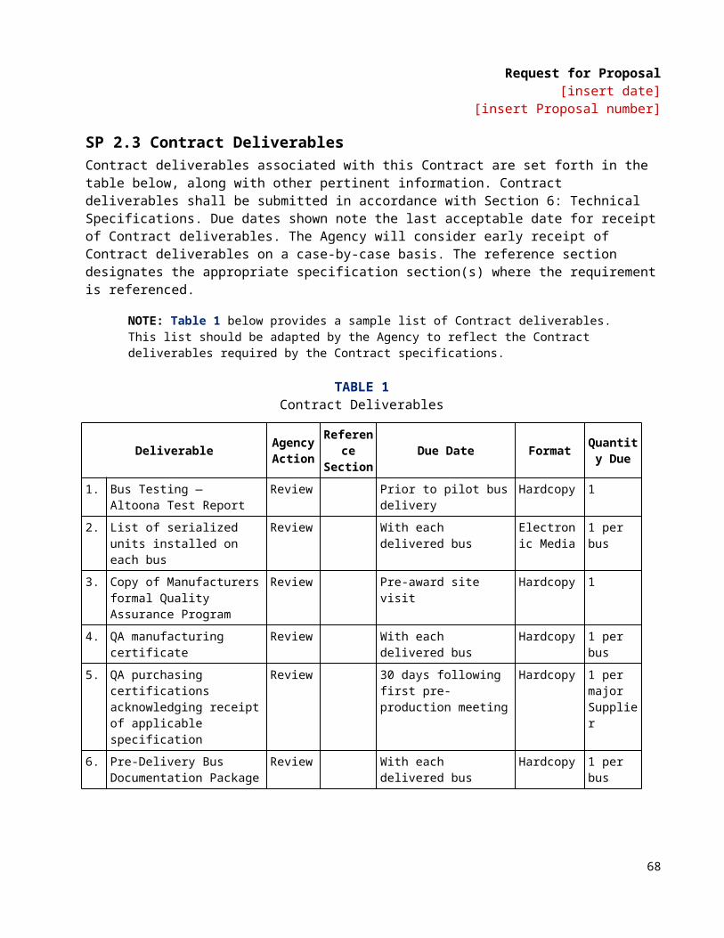
Request for Proposal[insert date]
[insert Proposal number]
Service Pressure. The settled pressure at a uniform gas temperature of 21 °C (70 °F) and full gas content. It is the pressure for which the equipment has been constructed, under normal conditions. Also referred to as the nominal service pressure or working pressure.
Settled Pressure. The gas pressure when a given settled temperature, usually 21 °C (70 °F), is reached.
Settled Temperature. The uniform gas temperature after any change in temperature caused by filling has dissipated.
Solid State Alternator. A module that converts high-voltage DC to low-voltage DC (typically 12/24 volt systems).
Sources of Ignition. Devices or equipment that because of their modes of use or operation, are capable of providing sufficient thermal energy to ignite flammable compressed natural gas-air mixtures when introduced into such a mixture, or when such a mixture comes into contact with them
Special Tools. Tools not normally stocked by the Agency.
Specification. A particular or detailed statement, account, or listing of the various elements, materials, dimensions, etc. involved in the manufacturing and construction of a product.
Standard. A firm guideline from a consensus group.
Standards. Standards referenced in “Part 5: Technical Specifications” are the latest revisions unless otherwise stated.
Standee Line. A line marked across the bus aisle to designate the forward area that passengers may not occupy when the bus is moving.
State of Charge (SOC). Quantity of electric energy remaining in the battery relative to the maximum rated Amp hour (Ah) capacity of the battery expressed in percent. This is a dynamic measurement used for the energy storage system. A full SOC indicates that the energy storage system cannot accept further charging from the engine driven generator or the regenerative braking system.
Stress Loops. The “pig-tails” commonly used to absorb flexing in piping.
Structure. The structure shall be defined as the basic body, including floor deck material and installation, load bearing external panels, structural components, axle mounting provisions and suspension beams and attachment points.
Thermally Activated Gas Relief Device. A relief device that is activated by high temperatures and generally contains a fusible material.
NOTE: Since this is a thermally activated device, it does not protect against over-pressure from improper charging practices.
Wheelchair. A mobility aid belonging to any class of three- or four-wheeled devices, usable indoors, designed for and used by individuals with mobility impairments, whether operated manually or powered.
70
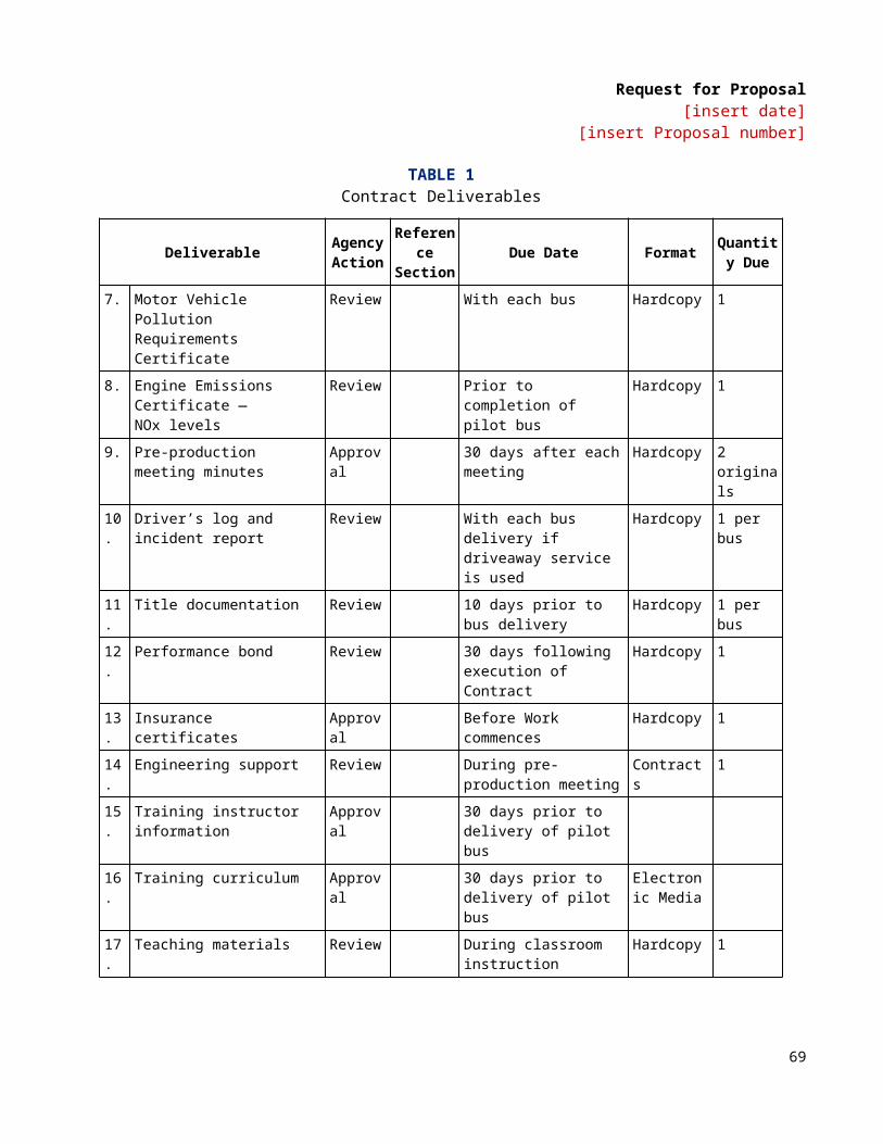
Request for Proposal[insert date]
[insert Proposal number]
A “common wheelchair” is such a device that does not exceed 30 in. in width and 48 in. in length measured 2 in. above the ground, and does not weigh more than 600 lbs when occupied.
TS 3. Referenced Publications The documents or portions thereof referenced within this specification shall be considered part of the requirements of the specification. The edition indicated for each referenced document is the current edition, as of the date of the APTA issuance of this specification.
TS 4. Legal Requirements The Contractor shall comply with all applicable federal, state and local regulations. These shall include but not be limited to ADA, as well as state and local accessibility, safety and security requirements. Local regulations are defined as those below the state level.
Buses shall meet all applicable FMVSS and shall accommodate all applicable FMCSR regulations in effect at location of the Agency and the date of manufacture.
In the event of any conflict between the requirements of these specifications and any applicable legal requirement, the legal requirement shall prevail. Technical requirements that exceed the legal requirements are not considered to conflict.
TS 5. Overall Requirements The Contractor shall ensure that the application and installation of major bus subcomponents and systems are compliant with all such subcomponent vendors’ requirements and recommendations. Contractor and Agency shall identify subcomponent vendors that shall submit installation/application approval documents with the completion of a pilot or lead bus. Components used in the vehicle shall be of heavy-duty design and proven in transit service.
TS 5.1 WeightIt shall be a design goal to construct each bus as light in weight as possible without degradation of safety, appearance, comfort, traction or performance.
Buses at a capacity load shall not exceed the tire factor limits, brake test criteria or structural design criteria.
TS 5.2 Capacity The vehicle shall be designed to carry the gross vehicle weight, which shall not exceed the bus GVWR.
TS 5.3 Service Life The minimum useful design life of the bus in transit service shall be at least twelve (12) years or 500,000 miles. It shall be capable of operating at least 40,000 miles per year, including the 12th year.
TS 5.4 Maintenance and Inspection Scheduled maintenance tasks shall be related and shall be, in accordance with the manufacturer’s recommended preventative maintenance schedule (along with routine daily service performed during the fueling operations).
71

Request for Proposal[insert date]
[insert Proposal number]
Test ports, as required, shall be provided for commonly checked functions on the bus, such as air intake, exhaust, hydraulic, pneumatic, charge-air and engine cooling systems.
The coach manufacturer shall give prime consideration to the routine problems of maintaining the vehicle. All coach components and systems, both mechanical and electrical, which will require periodic physical Work or inspection processes shall be installed so that a minimum of time is consumed in gaining access to the critical repair areas. It shall not be necessary to disassemble portions of the coach structure and/or equipment such as seats and flooring under seats in order to gain access to these areas. Each coach shall be designed to facilitate the disassembly, reassembly, servicing or maintenance, using tools and equipment that are normally available as standard commercial items.
Requirements for the use of unique specialized tools will be minimized. The body and structure of the coach shall be designed for ease of maintenance and repair. Individual panels or other equipment which may be damaged in normal service shall be repairable or replaceable. Ease of repair shall be related to the vulnerability of the item to damage in service.
Contractor shall provide a list of all special tools and pricing required for maintaining this equipment. Said list shall be submitted as a supplement to the Pricing Schedule.
NOTE: Tools such as compartment door keys, bellows gauges and other tools that are required for daily maintenance and inspections shall not be included in the special tool list and shall be furnished for each coach.
TS 5.5 InterchangeabilityUnless otherwise agreed, all units and components procured under this Contract, whether provided by Suppliers or manufactured by the Contractor, shall be duplicates in design, manufacture and installation to ensure interchangeability among buses in each order group in this procurement. This interchangeability shall extend to the individual components as well as to their locations in the buses. These components shall include, but are not limited to, passenger window hardware, interior trim, lamps, lamp lenses and seat assemblies. Components with non-identical functions shall not be, or appear to be, interchangeable.
Any one component or unit used in the construction of these buses shall be an exact duplicate in design, manufacture and assembly for each bus in each order group in this Contract. Contractor shall identify and secure approval for any changes in components or unit construction provided within a Contract.
In the event that the Contractor is unable to comply with the interchangeability requirement, the Contractor must notify the Agency and obtain the Agency’s prior written approval, including any changing in pricing.
Agency shall review proposed product changes on a case-by-case basis and shall have the right to require extended warranties to ensure that product changes perform as least as well as the originally supplied products.
TS 5.6 Training
NOTE: The following is illustrative; the Agency should carefully specify its training requirements.
The Contractor shall have at least one qualified instructor who shall be available at the Agency’s property for [insert number] calendar days between the hours of [insert starting time] and [insert closing time] per month for [insert number] months prior to, and [insert number] months after, acceptance of the first bus. Instructor(s)
72
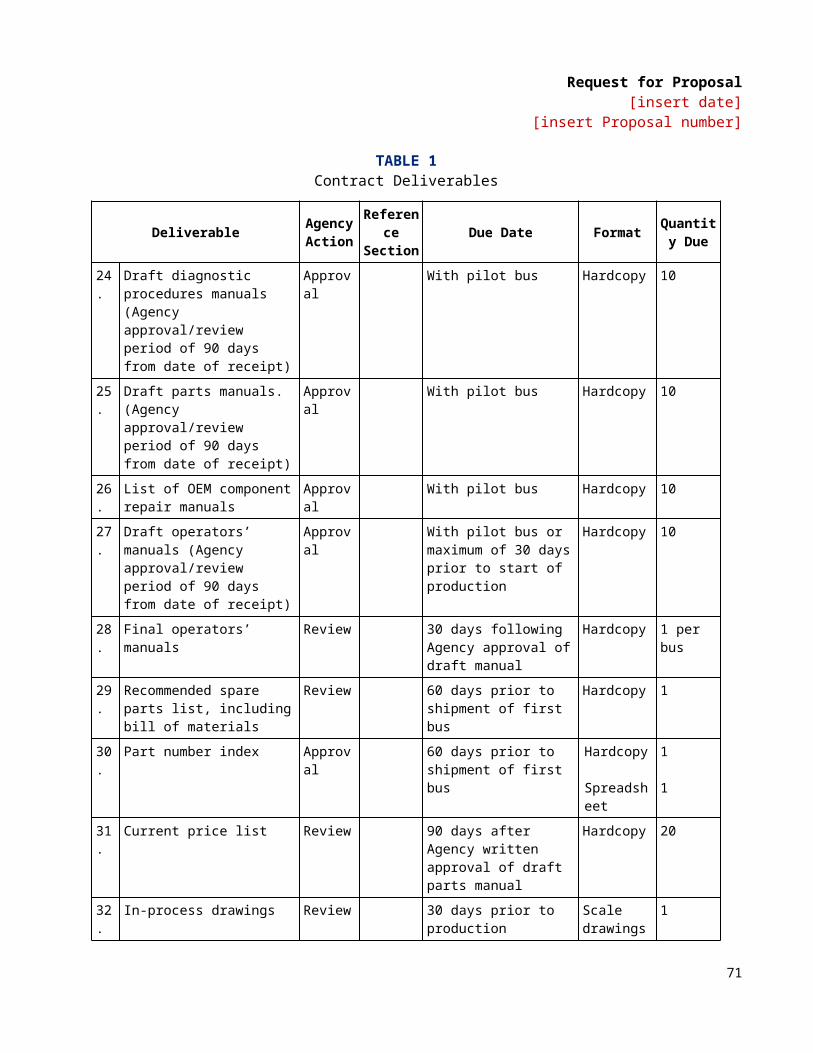
Request for Proposal[insert date]
[insert Proposal number]
shall conduct schools and advise the personnel of the Agency on the proper operation and maintenance of the equipment. The Contractor also shall provide visual and other teaching aids (such as manuals, slide presentations and literature) for use by the Agency’s own training staff and which become the property of the Agency.
NOTE: The Agency should insert language that specifies the hours when it wants the training to occur, the total number of hours of instruction it wants to be provided, what items it expects the curriculum to cover and the format in which it expects the training and teaching aids to be provided (print, DVD, etc.).
Technical/Service Representatives The Contractor shall, at its own expense, have one or more competent technical service representatives available on request to assist the Agency in the solution of engineering or design problems within the scope of the specifications that may arise during the warranty period. This does not relieve the Contractor of responsibilities under the provisions of “Section 7: Warranty Requirements.”
TS 5.7 Operating Environment The bus shall achieve normal operation in ambient temperature ranges of 10 ºF to 115 ºF, at relative humidity between 5 percent and 100 percent, and at altitudes up to 3000 feet above sea level. Degradation of performance due to atmospheric conditions shall be minimized at temperatures below 10 °F, above 115 °F or at altitudes above 3000 feet. Altitude requirements above 3000 feet will need separate discussions with the engine manufacturer to ensure that performance requirements are not compromised. Speed, gradability and acceleration performance requirements shall be met at, or corrected to, 77 °F, 29.31 in. Hg, dry air per SAE J1995.
TS 5.8 NoiseInterior NoiseThe combination of inner and outer panels and any material used between them shall provide sufficient sound insulation so that a sound source with a level of 80 dBA measured at the outside skin of the bus shall have a sound level of 65 dBA or less at any point inside the bus. These conditions shall prevail with all openings, including doors and windows, closed and with the engine and accessories switched off.
The bus-generated noise level experienced by a passenger at any seat location in the bus shall not exceed 80 dBA. The driver area shall not experience a noise level of more than 75 dBA.
An exception shall be made for the turntable area, which shall be considered a separate environment.
Exterior NoiseAirborne noise generated by the bus and measured from either side shall not exceed 80 dBA under full power acceleration when operated 0 to 35 mph at curb weight. The maximum noise level generated by the bus pulling away from a stop at full power shall not exceed 83 dBA. The bus-generated noise at curb idle shall not exceed 65 dBA. If the noise contains an audible discrete frequency, a penalty of 5 dBA shall be added to the sound level measured. The Contractor shall comply with the exterior noise requirements defined in local laws and ordinances identified by the Agency and SAE J366.
ALTERNATIVEAgency to state what noise should be required
73
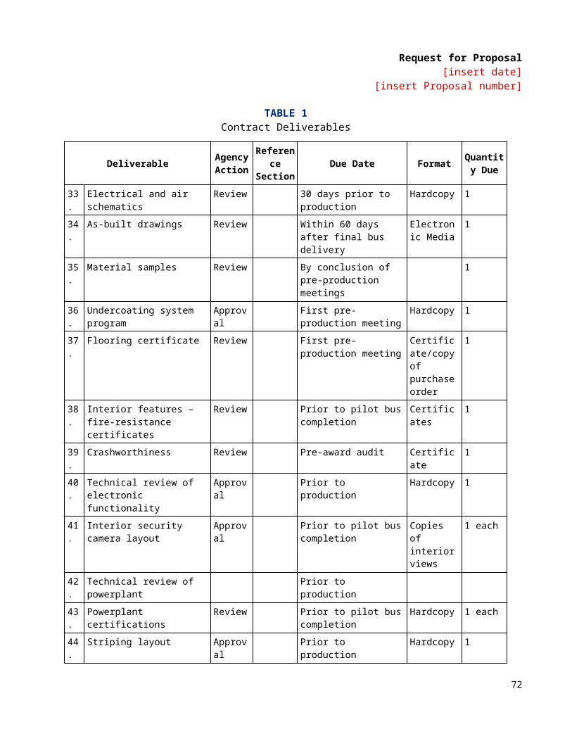
Request for Proposal[insert date]
[insert Proposal number]
TS 5.9 Fire Safety DEFAULTThe bus shall be designed and manufactured in accordance with all applicable fire safety and smoke emission regulations. These provisions shall include the use of fire-retardant/low-smoke materials, fire detection systems, bulkheads and facilitation of passenger evacuation.
ALTERNATIVENo fire suppression system
DEFAULTAll materials used in the construction of the passenger compartment of the bus shall be in accordance with the Recommended Fire Safety Practices defined in FMVSS 302, dated October 20, 1993. Materials entirely enclosed from the passenger compartment, such as insulation within the sidewalls and sub-floor, need not comply. In addition, smaller components and items, such as seat grab rails, switch knobs and small light lenses, shall be exempt from this requirement.
ALTERNATIVEAll materials used in the construction of the passenger compartment of the bus shall be in accordance with the Recommended Fire Safety Practices defined in FTA Docket 90, dated October 20, 1993. Materials entirely enclosed from the passenger compartment, such as insulation within the sidewalls and sub-floor, need not comply. In addition, smaller components and items, such as seat grab rails, switch knobs and small light lenses, shall be exempt from this requirement.
TS 5.10 Respect for the EnvironmentIn the design and manufacture of the bus, the Contractor shall make every effort to reduce the amount of potentially hazardous waste. In accordance with Section 6002 of the Resource Conservation and Recovery Act, the Contractor shall use, whenever possible and allowed by the specifications, recycled materials in the manufacture of the bus.
74
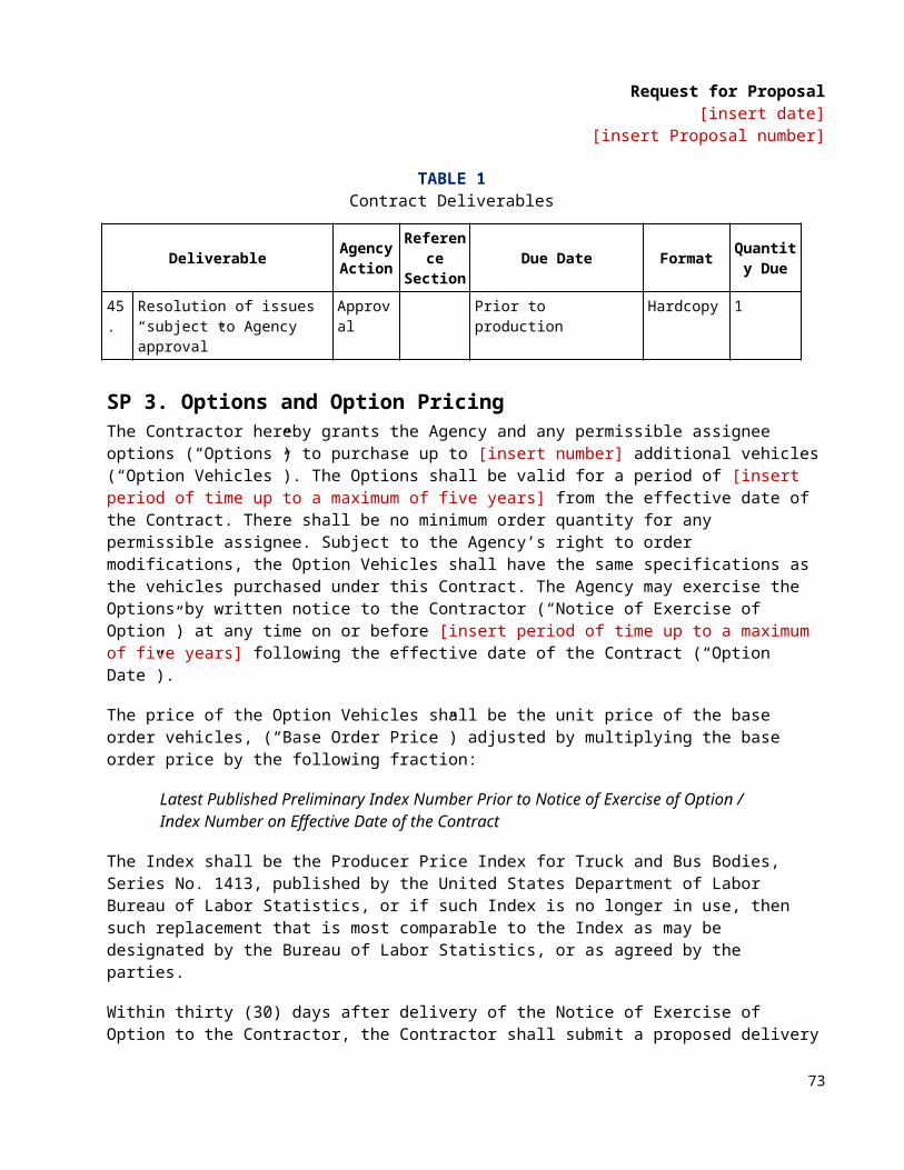
Request for Proposal[insert date]
[insert Proposal number]
DIMENSIONSTS 6. Physical SizeWith exceptions such as exterior mirrors, marker and signal lights, bumpers, fender skirts, washers, wipers, ad frames, cameras, object detection systems, bicycle racks, feelers and rub rails, the bus shall have the following overall dimensions as shown in Figure 1 at static conditions and design height.
FIGURE 1Transit Bus Exterior Dimensions
TS 6.1 Bus LengthFor ease of use, the following tolerances will be allowable for each given bus length. Bus length is determined as the measurement from bumper to bumper.
• 30-ft bus: 29 ft, 11 in. to 34 ft, 11 in.• 35-ft bus: 35 ft to 39 ft, 11 in.• 40-ft bus: 40 ft to 44 ft, 11 in.• 45-ft bus: 45 to 47 ft• 60-foot (articulated): 59 to 65 ft
75
Request for Proposal[insert date]
[insert Proposal number]
TS 6.2 Bus WidthDEFAULT102-in. Width BusBody width shall be 102 in. (+0, -1 in.).
ALTERNATIVE96-in. Width BusBody width shall be 96 in. (+0, -1 in.).
TS 6.3 Bus HeightDEFAULT Maximum Overall HeightMaximum overall height shall be 140 in., including all rigid, roof-mounted items such as A/C, exhaust, fuel system and cover, etc.
ALTERNATIVEMaximum HeightMaximum height shall be specified by Agency.
TS 6.4 Step HeightDEFAULTThe step height shall not exceed 16.5 in. at either doorway without kneeling and shall not exceed 15.5 in. at the step. A maximum of two steps is allowed to accommodate a raised aisle floor in the rear of the bus.
ALTERNATIVE Center door on articulated bus may have more than two steps.
ALTERNATIVEHigh floor bus floor height shall not exceed 35 in. at either doorway, without kneeling.
TS 6.5 Underbody ClearanceThe bus shall maintain the minimum clearance dimensions as shown in Figure 2 and defined in SAE Standard J689, regardless of load up to the gross vehicle weight rating.
TS 6.6 Ramp ClearancesThe approach angle is the angle measured between a line tangent to the front tire static loaded radius arc and the initial point of structural interference forward of the front tire to the ground.
The departure angle is the angle measured between a line tangent to the rear tire static loaded radius arc and the initial point of structural interference rearward of the rear tire to the ground.
76
Request for Proposal[insert date]
[insert Proposal number]
The breakover angle is the angle measured between two lines tangent to the front and rear tire static loaded radius and intersecting at a point on the underside of the vehicle that defines the largest ramp over which the vehicle can roll.
TABLE 2Breakover Angle
Angle 30- to 45-ft Bus 60-ft BusApproach 8.6 degrees (min.) 9 degrees (min.)Front breakover 8 degrees (min.) 10.2 degrees (min.)Rear breakover (articulated only) n/a 8.7 degrees (min.)Departure 8.7 degrees (min.) 9 degrees (min.)
TS 6.7 Ground ClearanceGround clearance shall be no less than 9 in., (8 in. at jacking pad) except within the axle zone and wheel area.
Axle zone clearance, which is the projected area between tires and wheels on the same axial centerline, shall be no less than 5.4 in.
Wheel area clearance shall be no less than 8 in. for parts fixed to the bus body and 6 in. for parts that move vertically with the axles.
77

Request for Proposal[insert date]
[insert Proposal number]
FIGURE 2Transit Bus Minimum Road Clearance
TS 6.8 Floor HeightHeight of the step above the street shall be no more than 16 in. measured at the centerline of the front and rear doorway. The floor may be inclined along the longitudinal axis of the bus, and the incline shall not exceed 3.5 degrees off the horizontal except locally at the doors where 2 degree slope toward the door is allowed. All floor measurements shall be with the bus at the design running height and on a level surface and with the standard installed tires. A maximum of two steps is allowed to accommodate a raised aisle floor in the rear of the bus.
TS 6.9 Interior Headroom Headroom above the aisle and at the centerline of the aisle seats shall be no less than 78 in. in the forward half of the bus tapering to no less than 74 in. forward of the rear settee. At the centerline of the window seats, headroom shall be no lower than 65 in., except for parcel racks and reading lights, if specified. Headroom at the back of the rear bench seat may be reduced to a minimum of 56 in., but it shall increase to the ceiling height at the front of the seat cushion. In any area of the bus directly over the head of a seated passenger and positioned where a passenger entering or leaving the seat is prone to strike his or her head, padding shall be provided on the overhead paneling.
78
Request for Proposal[insert date]
[insert Proposal number]
TS 6.10 Aisle WidthThe minimum clear aisle width between pairs of transverse seats with all attached hardware shall be at least 22 in.
The aisle width between the front wheelhouses shall be at least 35.5 in., and the entire area between the front wheelhouses shall be available for passengers and mobility aid devices.
VEHICLE PERFORMANCE TS 7. Power Requirements The propulsion system shall be sized to provide sufficient power to enable the bus to meet the defined acceleration, top speed, and gradability requirements, and operate all propulsion-driven accessories using actual road test results and computerized vehicle performance data.
TS 7.1 Top Speed The bus shall be capable of achieving a top speed of 65 mph on a straight, level road at GVWR with all accessories operating. The bus shall be capable of safely maintaining the vehicle speed according to the recommendations by the tire manufacturer.
NOTE: Values are assumed to be sustained. Manufacturer shall supply Agency with data if there is a variance between peak performance and sustained vehicle performance.
TS 7.2 Gradability Gradability requirements shall be met on grades with a dry commercial asphalt or concrete pavement at GVWR with all accessories operating.
DEFAULTThe propulsion system and drivetrain shall enable the bus to achieve and maintain a speed of 40 mph on a 2½ percent ascending grade and 15 mph on a 10 percent ascending grade continuous.
ALTERNATIVE[Agency will provide operating profile information to the Contractor.]
NOTE: Values are assumed to be sustained. Manufacturer shall supply Agency with data if there is a variance between peak performance and sustained vehicle performance.
TS 7.3 Acceleration The acceleration shall meet the requirements below and shall be sufficiently gradual and smooth to prevent throwing standing passengers off-balance. Acceleration measurement shall commence when the accelerator is depressed.
TABLE 3Maximum Start Acceleration Times on a Level Surface1
Speed (mph) Maximum time(seconds)
10 5
79
Request for Proposal[insert date]
[insert Proposal number]
20 1030 1840 3050 60
Top speed1. Vehicle weight = GVWR
HybridThe propulsion and braking systems shall meet the performance requirements of the Duty Cycle.
Braking application and performance shall remain consistent regardless of hybrid system State of Charge (SOC) or other variances related to regenerative braking.
DEFAULTThe system shall be programmable to allow optimization of acceleration and deceleration rate. Performance may be affected when reprogramming. The manufacturer shall supply the new performance data.
TS 7.4 Operating Range The operating range of the coach shall be designed to meet the operating profile as stated in the “Design Operating Profile” section.
TS 7.4.1 DieselDEFAULTThe operating range of the coach when run on the Altoona Test cycle shall be at least 350 mi (560 km) or 20 hrs with full fuel capacity.
ALTERNATIVEAgency to designate operating range.
TS 7.4.2 CNGDEFAULTThe operating range of the coach when run on the Altoona Test cycle shall be at least 350 mi or 20 hrs with an initial gas settled pressure of 3600 psi at 70 °F.
ALTERNATIVEAgency to designate operating range.
TS 7.4.3 HybridDEFAULTThe operating range of the coach when run on the design operating profile “Design Operating Profile” shall be at least 350 mi on a full tank of fuel.
80
Request for Proposal[insert date]
[insert Proposal number]
ALTERNATIVEAgency to designate operating range. [Add alternative hybrid system to provide an all electric range and operation to be defined by the Agency.]
TS 8. Fuel Economy (Design Operating Profile)Test results from the Altoona fuel economy tests or other applicable test procedures shall be provided to the Agency. Results shall include vehicle configuration and test environment information. Fuel economy data shall be provided for each design operating profile. The design operating profile is assumed to be defined by the Altoona fuel duty cycle.
Fuel economy tests shall be run on these four duty cycles.
Duty Cycles (avg speed)Manhattan: 6.8 mphOrange County: 12.7 mphUDDS: 19 mphIdle time
Procuring Agency will provide a percentage of each duty cycle that is representative of agency’s service.
0
10
20
30
40
50
0 200 400 600 800 1000 1200 1400 1600 1800 2000
Time (sec)
Vehi
cle
Spee
d (m
ph)
End of Test (1950 seconds)
Orange County Bus Cycle
81

Request for Proposal[insert date]
[insert Proposal number]
0
5
10
15
20
25
30
0 500 1000 1500 2000
Time (sec)
Vehi
cle
Spee
d (m
ph)
End of Test (2178 seconds)
Double Manhattan Bus Cycle
TS 8.1 HybridEnergy storage system state of charge correction methods stated in SAE J2711 shall be utilized.
POWERPLANTTS 9. EngineThe engine shall comply with applicable local, state, and/or federal emissions and useful life requirements. Components of the fuel management and/or control system shall have a design life of not less than 150,000 miles without replacement or major service. The lifetime estimate is based on the design operating profile.
The engine shall be equipped with an electronically controlled management system, compatible with either 12- or 24-volt power distribution. The engine control system shall be capable of transmitting and receiving electronic inputs and data from other drivetrain components and broadcasting that data to other vehicle systems. Communication between electronic drivetrain components and other vehicle systems shall be made using the communications networks. The engine’s electronic management system shall monitor operating conditions and provide instantaneous adjustments to optimize both engine and bus performance. The system shall be programmable to allow optimization of programmable features.
82

Request for Proposal[insert date]
[insert Proposal number]
The engine starting system shall be protected by an interlock that prevents its engagement when the engine is running. Special equipment or procedures may be employed to start the bus when exposed to temperatures less than 30 °F for a minimum of four hours without the engine in operation. All cold weather starting aids, engine heating devices and procedures shall be of the type recommended by the engine manufacturer and approved by the Agency. The integration of all systems on the vehicle relative to engine idle speed shall be the responsibility of the vehicle manufacturer to meet the requirements of the transit property.
The engine control system shall protect the engine against progressive damage. The system shall monitor conditions critical for safe operation and automatically derate power and/or speed and initiate engine shutdown as needed.
DEFAULTAutomatic Engine Protection/Shutdown Override FeatureA control shall be available to the operator/driver that when constantly depressed and released will delay the engine shutdown or allow the bus to be moved. Override action shall be recorded. This data shall be retrievable by the Agency.
ALTERNATIVENo requirement for an automatic engine protection/shutdown override feature.
TS 9.1 Engine (CNG)The engine shall meet all regulatory requirements when operating on fuel equal to CARB Specifications for Compressed Natural Gas #2292.5. The four predominant characteristics that must be met are Methane, Ethane, Butane, and Propane.
TS 9.2 Propulsion System (Hybrid)Propulsion System DescriptionThe bus shall be powered by a hybrid propulsion system. Function and operation of the bus shall be transparent to the Bus Operator and passengers. The OEM shall assure that the bus structure can successfully accept the installation of the propulsion system and be operated on the stated duty-cycle for a period of 12 years without a structural failure. At a minimum, propulsion system shall comply with applicable local, state, and/or federal emissions and useful life requirements. The propulsion system shall comply with local, state, and federal (maintenance) and other applicable sections.
The Hybrid Drive System shall be rated for the GVWR or greater of the bus.
Propulsion System ServiceThe propulsion system shall be arranged so that accessibility for all routine maintenance is assured. No special tools, other than dollies and hoists, shall be required to remove the propulsion system or any subsystems. However, the Agency shall recognize that properly rated test equipment and safe electrical work practices are essential when servicing high voltage hybrid components. The exhaust system, air cleaner, air compressor, starter (if used), alternator, radiator, all engine accessories, and any other component requiring service or replacement shall be easily removable. Contractor shall provide all specialty tools and diagnostic equipment required for maintaining the Propulsion System in accordance with Special Tools List.
83
Request for Proposal[insert date]
[insert Proposal number]
Primary Propulsion Unit and Traction MotorThe PPU and traction motor may be configured in a variety of methods dependent upon type of drive, series and/or parallel. The definition of motor in the context of this specification assumes the device can provide or consume energy as well as provide or retard mechanical motion.
Energy Storage and ControllerDesign and performance shall be provided to the Agency. Energy storage shall be of a commercial design capable of operating in the Agency transit environment. The primary charging of the energy storage system shall be accomplished by the on-board PPU and regenerative braking.
Thermal management will be provided to ensure optimal life and performance of the ESS over the environmental operating range.
Hybrid System Controller (HSC)The HSC regulates energy flow throughout hybrid system components in order to provide motive performance and accessory loads, as applicable, while maintaining critical system parameters (e.g., voltages, currents, temperatures, etc.) within specified operating ranges.
The controller shall monitor and process inputs and execute outputs as appropriate to control the operation of all propulsion system components.
Prime Power Unit (PPU)The PPU and related emission systems shall meet all applicable emissions and design/durability guidelines and standards.
Contractor shall provide Agency with expected durability of the PPU and related emission systems.
NOTE: Agency will provide desired fuel type.
DEFAULTSupplier shall recommend powerplant.
ALTERNATIVEAgency shall define required powerplant.
The PPU shall be equipped with an electronically controlled management system, compatible with multiplex wiring systems and either 12- or 24-volt electrical systems.
The engine shall have on-board diagnostic capabilities, able to monitor vital functions, store out-of-parameter conditions in memory, and communicate faults and vital conditions to service personnel. Diagnostic reader device connector ports, suitably protected against dirt and moisture, shall be provided in operator’s area and near or inside engine compartment. The on-board diagnostic system shall inform the operator via visual and/or audible alarms when out-of-parameter conditions exist for vital engine functions.
The engine starting system shall be protected by an interlock that prevents its engagement when the engine is running. Special equipment or procedures may be employed to start the engine when exposed to temperatures less than 30° F for a minimum of four hours without the engine in operation. All cold weather starting aids,
84

Request for Proposal[insert date]
[insert Proposal number]
engine heating devices and procedures shall be of the type recommended by the engine manufacturer and approved by the Agency.
DEFAULTStandard Requirements for a Fast Idle DeviceThe engine shall be equipped with an operator-controlled fast idle device. The fast idle control shall be a two-way switch mounted on the dash or side console and shall activate only with the transmission in neutral and the parking brake applied. ALTERNATIVEAutomatically Activated Fast Idle as RequiredThe fast idle device shall be activated and controlled automatically by the control system.
TS 10. Cooling SystemsThe cooling systems shall be of sufficient size to maintain all engine and transmission fluids and engine intake air at safe, continuous operating temperatures during the most severe operations possible and in accordance with engine and transmission manufacturers’ cooling system requirements. The cooling system fan controls should sense the temperatures of the operating fluids and the intake air, and if either is above safe operating conditions the cooling fan should be engaged. The fan control system shall be designed with a fail-safe mode of “fan on.” The cooling system shall meet the requirements stated in the operating environment.
TS 10.1 Engine CoolingA means of determining satisfactory engine coolant level shall be provided. A spring-loaded, push-button type valve or lever shall be provided to safely release pressure or vacuum in the cooling system with both it and the water filler no more than +/- 60 in. above the ground. Both shall be accessible through the same access door.
DEFAULTThe radiator and charge air cooler shall be of durable, corrosion-resistant construction with non-removable tanks.
ALTERNATIVEThe radiator and charge air cooler shall be of durable, corrosion-resistant construction with non-removable radiator headers.
ALTERNATIVEFor roof mounted radiators, a pressure filler will be provided in the engine compartment no more than +/- 60 in. above the ground.
DEFAULTNo screen in front of radiator
85
Request for Proposal[insert date]
[insert Proposal number]
ALTERNATIVEScreen in Front of Radiator The radiator input shall be protected by an easily cleanable screen designed to collect large debris. Radiators with a fin density greater than 12 fins per in. or a louvered slit design shall not be used. No heat-producing components or climate control system components shall be mounted between the engine cooling air intake aperture and the radiator. The radiator and charge air cooler shall be designed to withstand thermal fatigue and vibration associated with the installed configuration. The radiator and charge air cooler cores shall be easily cleaned (to include engine side core surface) with standard pressure-washing equipment.
DEFAULTStandard Requirement for Coolant FiltrationThe engine cooling system shall be equipped with a properly sized water filter with a spin-on element and an automatic system for releasing supplemental coolant additives as needed to replenish and maintain protection properties. When replacing the water filter, only the water in the filter will be lost.
ALTERNATIVENo requirement for coolant filtration
ALTERNATIVECoolant Filtration without Supplemental AdditivesThe engine cooling system shall be equipped with a properly sized water filter with a spin-on element. The filter shall not release or contain supplemental coolant additives.
DEFAULTStandard Control and Drive DesignControl and drive of the radiator and charge air cooler fan(s) shall be the Contractor’s standard design.
ALTERNATIVESelf-CleaningRadiator and charge air cooler fan(s) shall be electrically driven and capable of automated reverse operations for periodic self-cleaning of the radiator and charge air cooler.
DEFAULTStandard Mounting DesignMounting location of radiator and charge air cooler shall be the Contractor’s standard design.
ALTERNATIVEHigher Mounting DesignThe lower edge of the radiator and charge air cooler core(s) shall be mounted at a height no less than 3 ft above street level to minimize core fouling caused by dirt, debris, leaves, etc.
86

Request for Proposal[insert date]
[insert Proposal number]
DEFAULTCooling Fan ControlsThe cooling fan shall be temperature controlled, allowing the engine to reach operating temperature quickly.
TS 10.2 Charge Air CoolingDEFAULTThe charge air cooling system also referred to as after-coolers or inter-coolers shall provide maximum air intake temperature reduction with minimal pressure loss. The charge air radiator shall be sized and positioned to meet engine manufacturer’s requirements. The charge air radiator shall not be stacked ahead of or behind the engine radiator and shall be positioned as close to the engine as possible unless integrated with the radiator. Air ducting and fittings shall be protected against heat sources and shall be configured to minimize restrictions and maintain sealing integrity.
ALTERNATIVEIf roof mounted over vestibule area; the radiator, charge air cooler and oil cooler shall be stacked horizontally provided specified operating temperatures are maintained during the design operating profile at the temperature ranges outlined in the Design Operating Environment.
TS 10.3 Transmission CoolingThe transmission shall be cooled by a dedicated heat exchanger sized to maintain operating fluid within the transmission manufacturer’s recommended parameters of flow, pressure and temperature.. The transmission cooling system shall be matched to retarder and engine cooling systems to ensure that all operating fluids remain within recommended temperature limits established by each component manufacturer. The engine cooling system should provide coolant bypass flow to the transmission cooling system with the engine thermostats closed.
TS 10.4 Hybrid Drive System CoolingThermal management system shall maintain hybrid system components within design operating temperature limits.
TS 11. Transmission (Conventional Powertrain)The transmission shall be multiple speed, automatic shift with torque converter, retarder and electronic controls. Gross input power, gross input torque and rated input speed shall be compatible with the engine. The transmission shall be designed to operate for not less than 300,000 miles on the design operating profile without replacement or major service. The transmission should be easily removable without disturbing the engine and accessible for service.
The electronic controls shall be capable of transmitting and receiving electronic inputs and data from other drivetrain components and broadcasting that data to other vehicle systems. Communication between electronic drivetrain components and other vehicle systems shall be made using the communications networks. Electronic controls shall be compatible with either 12- or 24-volt power distribution, provide consistent shift quality and compensate for changing conditions such as variations in vehicle weight and engine power.
87

Request for Proposal[insert date]
[insert Proposal number]
DEFAULTA nominal brake pedal application of 6 to 10 psi shall be required by the driver to engage forward or reverse range from the neutral position to prevent sudden acceleration of the bus from a parked position.
ALTERNATIVEA nominal brake pedal application of 15 to 20 psi shall be required by the driver to engage forward or reverse range from the neutral position to prevent sudden acceleration of the bus from a parked position.
The electronically controlled transmission shall have on-board diagnostic capabilities, be able to monitor functions, store and time stamp out-of-parameter conditions in memory, and communicate faults and vital conditions to service personnel. The transmission shall contain built-in protection software to guard against severe damage. The on-board diagnostic system shall trigger a visual alarm to the driver when the electronic control unit detects a malfunction.
An electronic transmission fluid level monitoring and protection system shall be provided.
DEFAULTA brake pedal application of 6 to 10 psi shall be required by the driver to engage forward or reverse range from the neutral position to prevent sudden acceleration of the bus from a parked position.
ALTERNATIVEA brake pedal application of 15 to 20 psi shall be required by the driver to engage forward or reverse range from the neutral position to prevent sudden acceleration of the bus from a parked position.
DEFAULTNo Automatic Neutral FunctionThe transmission shall not incorporate an automatic neutral shift function.
ALTERNATIVEAutomatic Neutral Function with Manual Re-engagementThe transmission shall automatically shift to neutral whenever the door brake interlock is applied for five minutes. The driver shall be required to apply the service brake to re-engage forward range.
ALTERNATIVEAutomatic Neutral Function with Automatic Re-engagementThe transmission, when in forward direction, shall automatically shift the transmission to neutral when the vehicle registers zero road speed, engine is idle and service brakes are applied. If the status of any one or more of the three signals changes, the transmission immediately and automatically resumes forward mode operation.
88

Request for Proposal[insert date]
[insert Proposal number]
TS 12. RetarderThe powertrain shall be equipped with a retarder designed to extend brake lining service life. The application of the retarder shall cause a smooth blending of both retarder and service brake function and shall not activate the brake lights
Actuation of ABS and/or automatic traction control (ATC) shall override the operation of the brake retarder.
ALTERNATIVEBrake lights shall illuminate when the retarder is activated.
DEFAULTStandard Requirement for Retarder ActivationThe retarder shall be adjustable within the limits of the powertrain and activated when the brake pedal is depressed. The Agency will work with the OEM/drive system manufacturer to determine retarder performance settings.
ALTERNATIVEThrottle Pedal Activation of the RetarderThe retarder shall become partially engaged (approximately one-third of its total application, with a resulting deceleration of no greater than 0.077g) when the throttle pedal is completely released. Maximum retarder shall be achieved when brake pedal is depressed prior to engagement of service brakes, with a maximum resulting deceleration of approximately 0.20g in an empty bus. The resulting decelerations specified include the effects of engine braking, wind resistance and rolling resistance.
The thermostatically controlled cooling fan shall be activated when the retarder is engaged and the coolant temperature reaches the maximum operating temperature established by the engine and transmission manufacturers.
DEFAULTAccessible Retarder Disable Switch The retarder disable switch shall be accessible to the seated driver.
ALTERNATIVERetarder Disable Switch Not AccessibleThe retarder disable switch is not required to be accessible to the seated driver.
ALTERNATIVEDisabling retarder shall be recorded for Agency data collection.
ALTERNATIVEUnless specified by the transmission manufacturer, a retarder disable switch will not be supplied.
89
Request for Proposal[insert date]
[insert Proposal number]
TS 13. MountingAll powerplant mounting shall be mechanically isolated to minimize transfer of vibration to the body structure and provide a minimum clearance of 0.75 in. Mounts shall control the movement of the powerplant so as not to affect performance of belt-driven accessories or cause strain in piping and wiring connections to the powerplant.
TS 13.1 ServiceThe propulsion system shall be arranged for ease of access and maintenance. The Contractor shall list all special tools, fixtures or facility requirements recommended for servicing. The muffler, exhaust system, air cleaner, air compressor, starter, alternator, radiator, all accessories and any other component requiring service or replacement shall be easily removable and independent of the engine and transmission removal. An engine oil pressure gauge and coolant temperature gauge shall be provided in the engine compartment. These gauges shall be easily read during service and mounted in an area where they shall not be damaged during minor or major repairs.
DEFAULTEngine oil and the radiator filler caps shall be hinged to the filler neck and closed with spring pressure or positive locks to prevent leakage. All fluid fill locations shall be properly labeled to help ensure that correct fluid is added. All fillers shall be easily accessible with standard funnels, pour spouts and automatic dispensing equipment. All lubricant sumps shall be fitted with magnetic-type drain plugs.
ALTERNATIVEUnique Fluid (Lubricant) FillersThe engine, transmission and hydraulic reservoir shall each incorporate a unique lubricant fill fitting to prevent cross-contamination of lubricant types. Fitting types shall be specified by the Agency.
The engine and transmission shall be equipped with sufficient heavy-duty fuel and oil filters for efficient operation and to protect the engine and transmission between scheduled filter changes. All filters shall be easily accessible and the filter bases shall be plumbed to ensure correct reinstallation.
DEFAULTNo engine bypass oil filter.
ALTERNATIVECentrifugal, non-disposable engine bypass oil filter. DEFAULTEngine Oil Pressure and Coolant Temperature GaugesEngine oil pressure and coolant temperature gauges required in engine compartment.
ALTERNATIVEOil Pressure and Coolant Temperature GaugesNo engine oil pressure and coolant temperature gauges required in engine compartment.
90
Request for Proposal[insert date]
[insert Proposal number]
DEFAULTEngine Air CleanerAn air cleaner with a dry filter element and a graduated air filter restriction indicator shall be provided. The location of the air intake system shall be designed to minimize the entry of dust and debris and to maximize the life of the air filter. The engine air duct shall be designed to minimize the entry of water into the air intake system. Drainage provisions shall be included to allow any water/moisture to drain prior to entry into air filter.
TS 14. Hydraulic SystemsHydraulic system service tasks shall be minimized and scheduled no more frequently than those of other major coach systems. All elements of the hydraulic system shall be easily accessible for service or unit replacement. Critical points in the hydraulic system shall be fitted with service ports so that portable diagnostic equipment may be connected or sensors for an off-board diagnostic system permanently attached to monitor system operation when applicable. A tamper-proof priority system shall prevent the loss of power steering during operation of the bus if other devices are also powered by the hydraulic system.
The hydraulic system shall operate within the allowable temperature range as specified by the lubricant manufacturer.
DEFAULTNo requirement for hydraulic system sensors.
ALTERNATIVEHydraulic System SensorsSensors in the main hydraulic system, excluding those in the power steering system, shall indicate on the driver’s on-board diagnostic panel conditions of low hydraulic fluid level.
TS 14.1 Fluid LinesAll lines shall be rigidly supported to prevent chafing damage, Fatigue Failures, degradation and tension strain. Lines should be sufficiently flexible to minimize mechanical loads on the components. Lines passing through a panel, frame or bulkhead shall be protected by grommets (or similar devices) that fit snugly to both the line and the perimeter of the hole that the line passes through to prevent chafing and wear. Pipes and fluid hoses shall not be bundled with or used to support electrical wire harnesses.
Lines shall be as short as practicable and shall be routed or shielded so that failure of a line shall not allow the contents to spray or drain onto any component operable above the auto-ignition temperature of the fluid.
All hoses, pipes, lines and fittings shall be specified and installed per the manufacturer’s recommendations.
TS 14.2 Fittings and ClampsAll clamps shall maintain a constant tension at all times, expanding and contracting with the line in response to temperature changes and aging of the line material. The lines shall be designed for use in the environment where they are installed. For example, high-temperature resistant in the engine compartment, resistant to road salts near the road surface, and so on.
91

Request for Proposal[insert date]
[insert Proposal number]
Compression fittings shall be standardized to prevent the intermixing of components. Compression fitting components from more than one manufacturer shall not be mixed, even if the components are known to be interchangeable.
TS 14.3 Charge Air PipingCharge air piping and fittings shall be designed to minimize air restrictions and leaks. Piping shall be as short as possible, and the number of bends shall be minimized. Bend radii shall be maximized to meet the pressure drop and temperature rise requirements of the engine manufacturer. The cross-section of all charge air piping shall not be less than the cross-section of the intake manifold inlet. Any changes in pipe diameter shall be gradual to ensure a smooth passage of air and to minimize restrictions. Piping shall be routed away from heat sources as practicable and shielded as required to meet the temperature rise requirements of the engine manufacturer.
Charge air piping shall be constructed of stainless steel, aluminized steel or anodized aluminum, except between the air filter and turbocharger inlet, where piping may be constructed of fiberglass. Connections between all charge air piping sections shall be sealed with a short section of reinforced hose and secured with stainless steel constant tension clamps that provide a complete 360-degree seal.
TS 15. RadiatorRadiator piping shall be stainless steel or brass tubing, and if practicable, hoses shall be eliminated. Necessary hoses shall be impervious to all bus fluids. All hoses shall be secured with stainless steel clamps that provide a complete 360-degree seal. The clamps shall maintain a constant tension at all times, expanding and contracting with the hose in response to temperature changes and aging of the hose material.
TS 16. Oil and Hydraulic LinesOil and hydraulic lines shall be compatible with the substances they carry. The lines shall be designed and intended for use in the environment where they are installed. For example, high–temperature resistant in the engine compartment, resistant to road salts near the road surface, and so on. Lines within the engine compartment shall be composed of steel tubing where practicable, except in locations where flexible lines are required.
Hydraulic lines of the same size and with the same fittings as those on other piping systems of the bus, but not interchangeable, shall be tagged or marked for use on the hydraulic system only.
TS 17. Fuel TS 17.1 Fuel LinesFuel lines shall be securely mounted, braced and supported as designed by the bus manufacturer to minimize vibration and chafing and shall be protected against damage, corrosion or breakage due to strain or wear.
Manifolds connecting fuel containers shall be designed and fabricated to minimize vibration and shall be installed in protected locations to prevent line or manifold damage from unsecured objects or road debris.
Fuel hose and hose connections, where permitted, shall be made from materials resistant to corrosion and fuel and protected from fretting and high heat. Fuel hoses shall be accessible for ease of serviceability.
92
Request for Proposal[insert date]
[insert Proposal number]
DEFAULTFuel of choice.
ALTERNATIVE[Agency to specify fuel type.]
Fuel Lines, DieselFuel lines shall be capable of carrying the type of fuel specified by the Agency (i.e., up to B20 type fuel).
Fuel Lines, CNGFuel lines shall comply with NFPA-52. All tubing shall be a minimum of seamless Type 304 stainless steel (ASTM A269 or equivalent). Fuel lines and fittings shall not be fabricated from cast iron, galvanized pipe, aluminum, plastic, or copper alloy with content exceeding 70 percent copper. Pipe fittings and hoses shall be clear and free from cuttings, burrs or scale. Pipe thread joining material that is impervious to CNG shall be utilized as required. Fuel lines shall be identifiable as fuel lines only.
High-pressure CNG lines shall be pressure tested to a minimum of 125 percent of system working pressure prior to fueling. CNG, nitrogen or clean, dry air shall be used to pressure test the lines/assembly. The bus manufacturer shall have a documented procedure for testing the high pressure line assembly.
Fuel lines shall be securely mounted, braced and supported using “split-block” type or stainless steel P clamps; all mounting clamps shall be mounted to a rigid structure to minimize vibration and shall be protected against damage, corrosion or breakage due to strain, rubbing, or wear. “Floating clamps” (not mounted to a rigid structure) shall not be permitted. Fuel lines shall not be used to secure other components (wires, air lines, etc).
Manifolds connecting fuel containers shall be designed and fabricated to minimize vibration and shall be installed in protected location(s) to prevent line or manifold damage from unsecured objects or road debris.
Fuel hose connections, where permitted, shall be less than 48 in. in length, made from materials resistant to corrosion and action of natural gas, and protected from fretting and high heat and shall be supported approximately every 12 in.
TS 17.2 Design and Construction TS 17.2.1 Design and Construction, DieselFuel Tank(s)
DEFAULTThe fuel tank(s) shall be made of corrosion resistant steel
ALTERNATIVEThe fuel tank(s) shall be made of corrosion resistant stainless steel. The fuel tank shall be made of sufficiently heavy gauge 300 series or ASTM Spec. A240 stainless steel.
93
Request for Proposal[insert date]
[insert Proposal number]
ALTERNATIVEThe fuel tank(s) shall be made of aluminum material.
ALTERNATIVEThe fuel tank(s) shall be made of high-density cross-linked polyethylene plastic material.
ALTERNATIVEProtective shield mounted fully underneath the tank(s).
InstallationThe fuel tank(s) shall be securely mounted to the bus to prevent movement during bus maneuvers.
The fuel tank(s) shall be equipped with an external, hex head, drain plug. It shall be at least a ⅜-inch size and shall be located at the lowest point of the tank(s). The fuel tank(s) shall have an inspection plate or easily removable filler neck to permit cleaning and inspection of the tank(s) without removal from the bus. The tank(s) shall be baffled internally to prevent fuel-sloshing noise regardless of fill level. The baffles or fuel pickup location shall assure continuous full power operation on a 6 percent upgrade for 15 minutes starting with no more than 25 gallons of fuel over the unusable amount in the tank(s). The bus shall operate at idle on a 6 percent downgrade for 30 minutes starting with no more than 10 gallons of fuel over the unusable amount in the tank(s).
The materials used in mounting shall withstand the adverse effects of road salts, fuel oils, and accumulation of ice and snow for the life of the bus.
LabelingThe capacity, date of manufacture, manufacturer name, location of manufacture, and certification of compliance to Federal Motor Carrier Safety Regulation shall be permanently marked on the fuel tank(s). The markings shall be readily visible and shall not be covered with an undercoating material.
Fuel FillerThe fuel filler shall be located 7 to 32 feet behind the centerline of the front door on the curbside of the bus. The filler cap shall be retained to prevent loss and shall be recessed into the body so that spilled fuel will not run onto the outside surface of the bus.
The fuel lines forward of the engine bulkhead shall be in conformance to SAE Standards.
DEFAULTDry-break fuel fillerThe fuel filler shall accommodate a nozzle that forms a locked and sealed connection during the refueling process to eliminate spills. Fuel shall not be allowed to flow into the tank unless the nozzle has been properly coupled, locked and sealed to the filler. With the nozzle open, fuel shall enter the tank at a fill rate of not less than 40 gallons per minute of foam-free fuel without causing the nozzle to shut off before the tank is full. The nozzle shall automatically shut off when the tank is essentially full. Once disconnected, fuel shall not be allowed to flow through the nozzle at any time. Any pressure over 3 psi shall be relieved from the fuel tank
94
Request for Proposal[insert date]
[insert Proposal number]
automatically. An audible signal shall indicate when the tank is essentially full. The dry break system shall be compatible with the Agency’s system. The fuel filler cap shall be hinged.
ALTERNATIVEThe fuel filler shall accommodate a standard fuel nozzle. The nozzle shall automatically shut off when the tank is essentially full. An audible signal shall indicate when the tank is essentially full. The fuel filler cap shall be a screw on cap.
ALTERNATIVEThe fuel filler cap shall be hinged.
TS 17.2.2 Design and Construction, CNGFuel Containers/CylindersCNG fuel containers/cylinders must be designed, constructed, manufactured, and tested in accordance with at least one of the following:
U.S. Applications:• NFPA 52-Standard for Compressed Natural Gas (CNG) Vehicular Fuel Systems• FMVSS 304• Any local standard(s) specifically intended for CNG fuel containers
The design and construction of the fuel system supplied by the OEM shall comply with federal and local regulations.
Installation Fuel cylinders shall be installed in accordance with ANSI/IAS NGV2 - 1998, Basic Requirements for Compressed Natural Gas Vehicles (NGV) Fuel Containers and NFPA 52, Compressed Natural Gas (CNG) Vehicular Fuel Systems Code, 1998 edition Section 303. In the case of a low floor transit bus, the placement of tanks shall be limited to the roof of the vehicle or in the compartment above the engine of the vehicle.
Fuel cylinders, attached valves, pressure relief devices, and mounting brackets should be installed and protected so that their operation is not affected by bus washers and environmental agents such as rain, snow, ice or mud. These components should be protected from significant damage caused by road debris or collision.
The roof and above the engine mounted tanks shall be contained within a skeletal structure resembling a roll cage and contained within an enclosure. The enclosure shall incorporate a hinged clamshell type access. The access panels shall be designed to offer protection from weather and to be sacrificial as a means of providing an escape path to atmosphere upon rapid enclosure pressure rise. The latching method shall utilize quick release captive hardware that can be demonstrated to last the life of the bus. Additional shielding shall be provided surrounding end fittings and valves as needed. Shields shall be attached to the bus structure hinged in a manner that permits one mechanic to unlatch and swing the shield open for routine inspections. As practical, electrical components shall not be located within the roof enclosure and if unavoidable, they shall be intrinsically safe.
95
Request for Proposal[insert date]
[insert Proposal number]
CNG fueled buses shall be equipped with an active automatic gas detection system which shall annunciate unsafe levels of methane. The automatic gas detection system shall be integrated with an onboard fire suppression system.
ALTERNATIVEThe access panels shall also be interlocked via proximity sensors, such that, if other than in their fully closed/locked position, an interlock will prevent engine starter engagement, prevent selection of forward or reverse transmission and shall apply the brake interlock at speeds less than 3 mph.
Labeling CNG fuel systems shall be labeled in accordance with NFPA 52, “Compressed Natural Gas (CNG) Vehicular Fuel Systems Code,” 1998 edition.
Pressure Relief Devices (PRDs)PRDs must be designed, constructed, manufactured and tested in accordance with ANIS/IAS PRD1 - 1998, “Pressure Relief Devices for Natural Gas Vehicle (NGV) Fuel Containers” and ANSI/IAS NGV2-1998, “Basic Requirements for Compressed Natural Gas Vehicle (NGV) Fuel Containers.” All natural gas fuel system piping, including the PRD vent line, shall be stainless steel. All PRDs must be vented to outside.
Valves Valves must be installed in accordance with ANIS/IAS NGV2 - 1998, “Basic Requirements for Compressed Natural Gas Vehicle (NGV) Fuel Containers” and NFPA 52, “Standard for Compressed Natural Gas (CNG) Vehicular Fuel Systems.”
Fuel Filler The fuel filler shall be located 7 to 38 feet (on a 30-, 35- and 40-foot coach) behind the centerline of the front door on a side determined by the Agency. The filler cap shall be retained to prevent loss and shall be recessed into the body.
The fill and vent receptacles shall be located within an enclosure on the right side of the bus. The access door shall be sized to allow full viewing of gauges, ease of hookups and maneuver of fuel nozzle.
The fuel fill receptacle and vent receptacle attachment shall be robust and capable of routine fueling connects/disconnects without deflection or metal fatigue, and capable of withstanding mechanical loads induced by a fueling drive away incident without attachment failure.
ALTERNATIVEThe access door interlock shall also power “on” the fuel level gauges/illumination when in the open position.
ALTERNATIVEA static ground plug shall be installed near the fueling receptacle for grounding during refueling operations.
Fueling SystemThe CNG fueling port receptacle shall be an ANSI/AGA NGV1 or NGV2 certified receptacle as designated by the Agency. The coach shall be capable of being fueled by a nozzle determined by the Agency. The fueling port receptacle location shall be such that connection by fueling personnel can be performed without
96

Request for Proposal[insert date]
[insert Proposal number]
physical strain or interference. A dust cap shall be permanently “tethered” to the fueling port receptacle. The fueling port receptacle access door shall be equipped with an interlock sensor that disables the engine starting system when the access door is open, to prevent drive-aways. The interlock shall be of the type such that if the sensor fails, the coach will not start.
Fueling site characteristics such as pressure, flow rate, and temperature shall be provided by the Agency.
Defueling System The CNG defueling port shall be an NGV-3.1/CGA-12.3 certified receptacle. The CNG defueling port shall be located on the curbside of the coach, in a location that is compatible with the Agency’s defueling station operation. The de-fueling system shall incorporate the following characteristics:
• Dust cap permanently “tethered” to the defueling port.• Device(s) to prevent inadvertent defueling. Specifications to be provided by Agency.• Components compatible with Agency’s defueling operation.• The piping and fittings onboard the bus shall be sized to allow the fueling station to meet the
following operating parameters:
DEFAULTFuel system sized to allow a bus with 20,000 scf on board to defuel within 2.5 hours.
ALTERNATIVEThe atmospheric-vent system shall allow a bus with 20,000 scf of onboard CNG storage to defuel to atmospheric pressure within 80 minutes.
ALTERNATIVELocation/method of attaching CNG fuel system to earth ground.
TS 18. Emissions and ExhaustTS 18.1 Exhaust EmissionsThe engine and related systems shall meet all applicable emission and engine design guidelines and standards.
TS 18.2 Exhaust SystemExhaust gases and waste heat shall be discharged from the roadside rear corner of the roof. The exhaust pipe shall be of sufficient height to prevent exhaust gases and waste heat from discoloring or causing heat deformation to the bus. The entire exhaust system shall be adequately shielded to prevent heat damage to any bus component, including the exhaust after-treatment compartment area. The exhaust outlet shall be designed to minimize rain, snow or water generated from high-pressure washing systems from entering into the exhaust pipe and causing damage to the after-treatment.
TS 18.3 Exhaust Aftertreatment An exhaust aftertreatment system will be provided to ensure compliance to all applicable EPA regulations in effect.
97
Request for Proposal[insert date]
[insert Proposal number]
Diesel Exhaust Fluid InjectionIf required by the engine manufacturer to meet NOx level requirements specified by EPA, a DEF injection system will be provided. The DEF system will minimally include a tank, an injector, a pump, an ECM and a selective catalytic converter. The tanks shall be designed to store DEF in the operating environment described in the “Operating Environment” section. The DEF fluid lines shall be designed to prevent the DEF from freezing. The DEF injection system shall not be damaged from a cold soak at 10 °F.
TS 18.4 Particulate Aftertreatment If required by the engine manufacturer to meet particulate level requirements specified by EPA, a particulate trap will be provided. The particulate trap shall regenerate itself automatically if it senses clogging. Regeneration cycles and conditions will be defined by the engine manufacturer.
STRUCTURETS 19. General TS 19.1 DesignThe structure of the bus shall be designed to withstand the transit service conditions typical of an urban duty cycle throughout its service life. The vehicle structural frame shall be designed to operate with minimal maintenance throughout the 12-year design operating profile. The design operating profile specified by the Agency shall be considered for this purpose.
TS 20. Altoona TestingPrior to acceptance of first bus, the vehicle must have completed any FTA-required Altoona testing. Any items that required repeated repairs or replacement must undergo the corrective action with supporting test and analysis. A report clearly describing and explaining the failures and corrective actions taken to ensure any and all such failures will not occur shall be submitted to the Agency.
DEFAULTIf available, the Altoona Test Report shall be provided to the Agency with the Proposal submittal. If not available, then the report shall be provided prior to first acceptance of bus.
ALTERNATIVEAltoona Test Report Provided to Agency Prior to Start of Bus ProductionPrior to the start of any bus manufacturing or assembly processes, the structure of the proposed bus model shall have undergone appropriate structural testing and/or analysis, including the complete regimen of FTA required Altoona tests. Prior to assembly of the first bus, the OEM shall provide the Agency with a completed report of Altoona testing for the proposed bus model along with a plan of corrective action to address deficiencies, breakdowns and other issues identified during Altoona testing. The bus model tested shall match the bus model proposed for procurement, including structure, axles and drive-train. Base model and partial Altoona test reports are acceptable when the combination of these tests adequately represents the proposed bus model.
98
Request for Proposal[insert date]
[insert Proposal number]
TS 20.1 Structural ValidationDEFAULT Baseline Structural AnalysisThe structure of the bus shall have undergone appropriate structural testing and/or analysis. At minimum, appropriate structural testing and analysis shall include Altoona testing or Finite Element Analysis (FEA).
ALTERNATIVEDetailed Structural AnalysisThe structure of the proposed bus model shall have undergone structural testing prior to assembly of the first bus. The OEM shall provide the Agency with completed reports of other structural tests as specified by the Agency.
TS 21. Distortion The bus, loaded to GVWR and under static conditions, shall not exhibit deflection or deformation that impairs the operation of the steering mechanism, doors, windows, passenger escape mechanisms or service doors. Static conditions shall include the vehicle at rest with any one wheel or dual set of wheels on a 6 in. curb or in a 6 in. deep hole.
TS 22. Resonance and Vibration All structure, body and panel-bending mode frequencies, including vertical, lateral and torsional modes, shall be sufficiently removed from all primary excitation frequencies to minimize audible, visible or sensible resonant vibrations during normal service.
TS 22.1 Engine Compartment BulkheadsThe passenger and engine compartment shall be separated by fire-resistant bulkheads. The engine compartment shall include areas where the engine and exhaust system are housed. This bulkhead shall preclude or retard propagation of an engine compartment fire into the passenger compartment and shall be in accordance with the Recommended Fire Safety Practices defined in FTA Docket 90A, dated October 20, 1993. Only necessary openings shall be allowed in the bulkhead, and these shall be fire-resistant. Any passageways for the climate control system air shall be separated from the engine compartment by fire-resistant material. Piping through the bulkhead shall have fire-resistant fittings sealed at the bulkhead. Wiring may pass through the bulkhead only if connectors or other means are provided to prevent or retard fire propagation through the bulkhead. Engine access panels in the bulkhead shall be fabricated of fire-resistant material and secured with fire-resistant fasteners. These panels, their fasteners and the bulkhead shall be constructed and reinforced to minimize warping of the panels during a fire that will compromise the integrity of the bulkhead.
TS 22.2 CrashworthinessThe bus body and roof structure shall withstand a static load equal to 150 percent of the curb weight evenly distributed on the roof with no more than a 6 in. reduction in any interior dimension. Windows shall remain in place and shall not open under such a load. These requirements must be met without the roof-mounted equipment installed.
99

Request for Proposal[insert date]
[insert Proposal number]
The bus shall withstand a 25 mph impact by a 4000-pound automobile at any side, excluding doorways, along either side of the bus with no more than 3 in. of permanent structural deformation at seated passenger hip height. This impact shall not result in sharp edges or protrusions in the bus interior.
Exterior panels below 35 in. from ground level shall withstand a static load of 2000 lbs applied perpendicular to the bus by a pad no larger than 5 sq in. This load shall not result in deformation that prevents installation of new exterior panels to restore the original appearance of the bus.
TS 23. CorrosionThe bus flooring, sides, roof, understructure and axle suspension components shall be designed to resist corrosion or deterioration from atmospheric conditions and de-icing materials for a period of 12 years or 500,000 miles, whichever comes first. It shall maintain structural integrity and nearly maintain original appearance throughout its service life, with the Agency’s use of proper cleaning and neutralizing agents.
All materials that are not inherently corrosion resistant shall be protected with corrosion-resistant coatings. All joints and connections of dissimilar metals shall be corrosion resistant and shall be protected from galvanic corrosion. Representative samples of all materials and connections shall withstand a two-week (336-hour) salt spray test in accordance with ASTM Procedure B-117 with no structural detrimental effects to normally visible surfaces and no weight loss of over 1 percent.
DEFAULTCorrosion-Resistance Requirements for Exposed and Interior Surfaces of Tubing Below Lower Window LevelAll exposed surfaces and the interior surfaces of tubing and other enclosed members below lower window line shall be corrosion resistant through application of a corrosion protection system.
ALTERNATIVECorrosion Resistance Requirements for Exposed and Interior Surfaces of Tubing Throughout Entire VehicleAll exposed surfaces and the interior surfaces of tubing and other enclosed members shall be corrosion resistant through application of a corrosion protection system.
ALTERNATIVEAdditional Corrosion Resistance RequirementsThe vehicle shall be constructed using only inherently corrosion-resistant materials and fasteners such as stainless steel or composites to minimize deterioration. The structure shall not require corrosion-preventive coatings or after-treatments, either during construction or throughout the service life of the vehicle.
TS 24. TowingEach towing device shall withstand, without permanent deformation, tension loads up to 1.2 times the curb weight of the bus within 20 degrees of the longitudinal axis of the bus. If applicable, the rear towing device(s) shall not provide a toehold for unauthorized riders. The method of attaching the towing device shall not require the removal, or disconnection, of front suspension or steering components. Removal of the bike rack is permitted for attachment of towing devices.
A plug connector permanently mounted at the front of the bus shall provide for bus tail lamp, marker, stop and turn signal lamp operation as controlled from the towing vehicle. The connector shall include a spring-
100

Request for Proposal[insert date]
[insert Proposal number]
loaded dust- and water-resistant cap. Shop air connectors shall be provided at the front and rear of the bus and shall be capable of supplying all pneumatic systems of the bus with externally sourced compressed air. The location of these shop air connectors shall facilitate towing operations.
ALTERNATIVEProvision of Glad-Hand Type Connectors for TowingGlad-hand type connectors shall be provided at the front of the bus to allow the towing vehicle to control and operate the bus braking system during a towing operation.
DEFAULTLifted (Supported) Front Axle and Flat Towing CapabilityThe front towing devices shall allow attachment of adapters for a rigid tow bar and shall permit the lifting of the bus until the front wheels are clear off the ground in order to position the bus on the towing equipment by the front wheels. These devices shall also permit common flat towing.
ALTERNATIVELifted (Unsupported) Front Axle and Flat Towing CapabilityThe front towing devices shall allow attachment of adapters for a rigid tow bar and shall permit the lifting and towing of the bus, at curb weight, while the front wheels are clear off the ground. These devices shall also permit common flat towing.
Two rear recovery devices/tie downs shall permit lifting and towing of the bus for a short distance, such as in cases of an emergency, to allow access to provisions for front towing of bus. The method of attaching the tow bar or adapter shall require the specific approval of the Agency. Any tow bar or adapter exceeding 50 lbs should have means to maneuver or allow for ease of use and application. Each towing device shall accommodate a crane hook with a 1 in. throat.
TS 25. JackingIt shall be possible to safely jack up the bus, at curb weight, with a common 10-ton floor jack with or without special adapter, when a tire or dual set is completely flat and the bus is on a level, hard surface, without crawling under any portion of the bus. Jacking from a single point shall permit raising the bus sufficiently high to remove and reinstall a wheel and tire assembly. Jacking pads located on the axle or suspension near the wheels shall permit easy and safe jacking with the flat tire or dual set on a 6 in. high run-up block not wider than a single tire. The bus shall withstand such jacking at any one or any combination of wheel locations without permanent deformation or damage.
DEFAULTYellow PadsJacking pads shall be painted safety yellow.
ALTERNATIVEDecalsApply decals to identify location of jacking pads.
101
Request for Proposal[insert date]
[insert Proposal number]
ALTERNATIVEAlternate Color Pads[Jacking pad color to be specified by Agency.]
TS 26. HoistingThe bus axles or jacking plates shall accommodate the lifting pads of a two-post (or three-post if 60 ft articulated bus) hoist system. Jacking plates, if used as hoisting pads, shall be designed to prevent the bus from falling off the hoist. Other pads or the bus structure shall support the bus on jack stands independent of the hoist.
TS 27. FloorTS 27.1 DesignThe floor shall be essentially a continuous plane, except at the wheel housings and platforms. Where the floor meets the walls of the bus, as well as other vertical surfaces such as platform risers, the surface edges shall be blended with a circular section of radius not less than ¼ in. or installed in a fully sealed butt joint. Similarly, a molding or cover shall prevent debris accumulation between the floor and wheel housings. The vehicle floor in the area of the entrance and exit doors shall have a lateral slope not exceeding 2 degrees to allow for drainage.
DEFAULTBi-level Floor DesignThe floor design shall consist of two levels (bi-level construction). Aft of the rear door extending to the rear settee riser, the floor height may be raised to a height no more than 21 in. above the lower level, with equally spaced steps. An increase slope shall be allowed on the upper level, not to exceed 3.5 degrees off the horizontal.
ALTERNATIVESloped Floor DesignThe floor of the bus shall be of a sloped low floor design. Aft of the rear door extending to the rear settee riser, the floor may be sloped but shall not exceed 5.5 degrees off the horizontal.
ALTERNATIVEFloor DrainA floor drain of noncorrosive materials shall be provided on the bus behind the front, curbside wheelhouse near the wall to help drain any water that may accumulate due to ice, snow, rain, etc. The drain pipe shall be approximately 1½ in. in diameter and shall extend no more than 5 in. below the floor. The drain pipe shall be fitted with a rubber drain spout to minimize or prevent air drafts to the interior of the bus. The strainer shall be firmly retained but also removable to allow flushing of any accumulated debris.
TS 27.2 StrengthThe floor deck may be integral with the basic structure or mounted on the structure securely to prevent chafing or horizontal movement and designed to last the life of the bus. Sheet metal screws shall not be used to retain the floor, and all floor fasteners shall be serviceable from one side only. Any adhesives, bolts or screws used to secure the floor to the structure shall last and remain effective throughout the life of the coach.
102
Request for Proposal[insert date]
[insert Proposal number]
Tapping plates, if used for the floor fasteners, shall be no less than the same thickness as a standard nut, and all floor fasteners shall be secured and protected from corrosion for the service life of the bus.
The floor deck shall be reinforced as needed to support passenger loads. At GVWR, the floor shall have an elastic deflection of no more than 0.60 in. from the normal plane. The floor shall withstand the application of 2.5 times gross load weight without permanent detrimental deformation. The floor, with coverings applied, shall withstand a static load of at least 150 lbs applied through the flat end of a ½ in. diameter rod, with 1/32-inch radius, without permanent visible deformation.
TS 27.3 ConstructionThe floor shall consist of the subfloor and the floor covering that will last the life of the bus. The floor as assembled, including the sealer, attachments and covering, shall be waterproof, non-hygroscopic and resistant to mold growth. The subfloor shall be resistant to the effects of moisture, including decay (dry rot). It shall be impervious to wood-destroying insects such as termites.
DEFAULTPressure-Preserved Plywood Panel Plywood shall be certified at the time of manufacturing by an industry-approved third-party inspection agency such as APA – The Engineered Wood Association (formerly the American Plywood Association). Plywood shall be of a thickness adequate to support design loads, manufactured with exterior glue, satisfy the requirements of a Group I Western panel as defined in PS 1-95 (Voluntary Product Standard PS 1-95, “Construction and Industrial Plywood”) and be of a grade that is manufactured with a solid face and back. Plywood shall be installed with the highest-grade, veneer side up. Plywood shall be pressure-treated with a preservative chemical and process such as alkaline copper quaternary (ACQ) that prevents decay and damage by insects. Preservative treatments shall utilize no EPA-listed hazardous chemicals. The concentration of preservative chemicals shall be equal to or greater than required for an above ground level application. Treated plywood will be certified for preservative penetration and retention by a third party inspection agency. Pressure-preservative treated plywood shall have a moisture content at or below 15 percent.
ALTERNATIVEComposite flooring.
ALTERNATIVEFlooring with manufactured noise-reduction characteristics.
TS 28. Platforms TS 28.1 Driver’s AreaThe covering of platform surfaces and risers, except where otherwise indicated, shall be the same material as specified for floor covering. Trim shall be provided along top edges of platforms unless integral nosing is provided.
DEFAULTNo specific trim material specified.
103
Request for Proposal[insert date]
[insert Proposal number]
ALTERNATIVESpecific trim required [specify].
TS 28.2 Driver’s PlatformThe driver’s platform shall be of a height such that, in a seated position, the driver can see an object located at an elevation of 42 in. above the road surface, 24 in. from the leading edge of the bumper. Notwithstanding this requirement, the platform height shall not position the driver such that the driver’s vertical upward view is less than 15 degrees. A warning decal or sign shall be provided to alert the driver to the change in floor level. Figure 3 illustrates a means by which the platform height can be determined, using the critical line of sight.
FIGURE 3Determining Platform Height
TS 28.3 FareboxFarebox placement should minimize impact to passenger access and minimize interference with the driver’s line of sight.
DEFAULTDriver Interface Required; Platform Needed to Bring Height to Driver Access If the driver’s platform is higher than 12 in., then the farebox is to be mounted on a platform of suitable height to provide accessibility for the driver without compromising passengers’ access.
104

Request for Proposal[insert date]
[insert Proposal number]
ALTERNATIVENo interface, no platform.
ALTERNATIVEStanchions Stanchions shall be located around the farebox.
TS 28.4 Rear Step Area to Rear AreaIf the vehicle is of a bi-level floor design, a rear step area shall be provided along the center aisle of the bus to facilitate passenger traffic between the upper and lower floor levels. This step area shall be cut into the rear platform and shall be approximately the aisle width, a minimum 12 in. deep and approximately half the height of the upper level relative to the lower level. The horizontal surface of this platform shall be covered with skid-resistant material with a visually contrasting nosing and shall be sloped slightly for drainage. A warning decal or sign shall be provided at the immediate platform area to alert passengers to the change in floor level.
TS 29. Wheel Housing TS 29.1 Design and ConstructionSufficient clearance and air circulation shall be provided around the tires, wheels and brakes to preclude overheating when the bus is operating on the design operating profile. Wheel housings shall be constructed of corrosion-resistant and fire-resistant material.
Interference between the tires and any portion of the bus shall not be possible in maneuvers up to the limit of tire adhesion with weights from curb weight to GVWR. Wheel housings shall be adequately reinforced where seat pedestals are installed. Wheel housings shall have sufficient sound insulation to minimize tire and road noise and meet all noise requirements of this specification.
Design and construction of front wheel housings shall allow for the installation of a radio or electronic equipment storage compartment on the interior top surface, or its use as a luggage rack.
The finish of the front wheel housings shall be scratch-resistant and complement interior finishes of the bus to minimize the visual impact of the wheel housing. If fiberglass wheel housings are provided, then they shall be color-impregnated to match interior finishes. The lower portion extending to approximately 10 to 12 in. above floor shall be equipped with scuff-resistant coating or stainless steel trim.
Wheel housings, as installed and trimmed, shall withstand impacts of a 2 in. steel ball with at least 200 ft-lbs of energy without penetration.
Wheel housings not equipped with seats or equipment enclosure shall have a horizontal assist mounted on the top portion of the housing no more than 4 in. higher than the wheel well housing.
ALTERNATIVEAbility to chain buses.
105
Request for Proposal[insert date]
[insert Proposal number]
TS 29.2 Articulated JointBuses shall be equipped with a turntable that permanently joins the lead unit and trailing unit sections, allows relative motion between the sections about the pitch and yaw axes, and allows a small amount of relative roll between the sections without damage. A rotating turntable connection shall be provided between the lead unit and trailing unit to serve as a floor and allow passenger access between the sections of the bus under all operating conditions. The turntable design shall provide for all horizontal and vertical turns that the bus is capable of making without introducing discontinuities between the turntable and adjacent vehicle floors.
The structures and finishes in the interconnecting section shall be designed to prevent passenger injury under all conditions. The turntable floor cover plate shall be supported so that there will be no honing of the floor plate, making it sharp at the outer edge. The gap between the floor and the turntable shall be minimized in order to prevent a tripping hazard. It shall be designed for ease of access for inspection and repairs of all devices that are part of it or devices that pass through the turntable area. Under-floor turntable components shall be easily accessible. Floor plates must be easily lifted and secured in the open position by one person for inspection and repairs. Turntable seats shall be quickly and easily removable by one person. The under-floor turntable area shall be completely enclosed by the bellows and bulkheads on the lead and trailing units to prevent drafts into the passenger compartment. The area between the turntable floor and the bellows shall be closed to prevent collection of trash in the bottom of the bellows. Closeouts shall be attached with removable fasteners. An access hatch shall be provided for routine maintenance (i.e., greasing, adjusting potentiometer, maintenance items).
An anti-jackknife joint shall be provided. This joint — by sensing vehicle speed, relative angle between the lead and trailing sections, throttle and braking actions, and any other necessary inputs — will control the degree of stiffness in the joint to ensure that the bus does not jackknife or operate in a dangerous or unsafe condition. The Agency shall approve the anti-jackknife joint. The interconnecting structure shall be designed to prevent separation of the lead and trailing units as a result of a road accident with a commercial or private vehicle. A means shall be provided so that the driver can override the control or recover from the situation. The bus shall be equipped with a reverse speed governor that shall apply the brake and accelerator interlocks when bus speed in reverse gear exceeds 1.5 mph, but the bus shall have sufficient power in reverse to back out of wheel locator depressions at a floor hoist. The proposed configuration of these devices and the reverse speed requirements shall be submitted for approval of the Agency.
Easy access shall be provided to overhead lines (electric, air, hydraulic, refrigerant) passing through the turntable. Hydraulic fittings shall be suitable for the given application and must be compatible with other fittings throughout the vehicle.
In order to prevent damage to the structure and electrical, air, hydraulic and refrigerant lines when the vertical or horizontal bending capabilities of the hinge are exceeded, the bus shall be provided with appropriate warning devices, brake interlocks and positive mechanical stops. These devices shall operate when the maximum bend angle is being approached in either plane.
TS 29.3 RacewayA raceway shall be provided through the turntable area to accommodate to maximum deflection of the turntable. The raceway shall prevent chafing, binding, rubbing, crimping or leakage of all hydraulic, air, fuel and system support lines, as well as all electrical and electronic cabling through or to the turntable area. Lines shall be secured, separated and labeled at the lead and trailing unit bulkheads. Separation shall be maintained on the flexible portion of all lines through the use of a raceway. All electrical terminations and hose fittings
106
Request for Proposal[insert date]
[insert Proposal number]
shall be easily visible and easily tightened or removed without removing any other component. Lines, routing, securement and labeling shall be approved by the Agency.
Bulkhead fitting shall be provided for all lines: air coolant, electrical and AC at both ends of the raceway. The bulkhead area shall be easily accessible for servicing.
TS 29.4 BellowsReplacement fabric type bellows with draft-free, no-sag bottom closure and water drains shall be provided between the lead and trailing sections to seal the bus interior and keep it free of water, dirt and drafts. Bellows hardware shall be corrosion resistant, and the under-floor area of the bellows shall be easy to clean when necessary. The passageway between the lead unit and trailing unit shall have an inside cross section that is as nearly equal as possible to the inside cross section of the bus bodies, with no tripping or pinching hazards created by the turntable cross section or closeouts. The bellows shall be durable, and its supporting structure and stiffeners shall support the bellows material in a neat, sag-free manner. The Contractor shall supply information on the actual service life achieved by the type of bellows being proposed. A sample of the bellows and attaching hardware may be requested for evaluation at the Agency’s option. Bellows shall be approved by the Agency.
ALTERNATIVEBellows liner.
CHASSISTS 30. SuspensionTS 30.1 General RequirementsThe front, rear and mid (if articulated) suspensions shall be pneumatic type. The basic suspension system shall last the service life of the bus without major overhaul or replacement. Adjustment points shall be minimized and shall not be subject to a loss of adjustment in service. Routine adjustments shall be easily accomplished by limiting the removal or disconnecting the components.
TS 30.2 AlignmentAll axles should be properly aligned so the vehicle tracks accurately within the size and geometry of the vehicle.
TS 30.3 Springs and Shock AbsorbersTS 30.3.1 Suspension TravelThe suspension system shall permit a minimum wheel travel of 2.75 in. jounce-upward travel of a wheel when the bus hits a bump (higher than street surface), and 2.75 in. rebound-downward travel when the bus comes off a bump and the wheels fall relative to the body. Elastomeric bumpers shall be provided at the limit of jounce travel. Rebound travel may be limited by elastomeric bumpers or hydraulically within the shock absorbers. Suspensions shall incorporate appropriate devices for automatic height control so that regardless of load the bus height relative to the centerline of the wheels does not change more than ½ in. at any point from the height required. The safe operation of a bus cannot be impacted by ride height up to 1 in. from design normal ride height.
107
Request for Proposal[insert date]
[insert Proposal number]
TS 30.3.2 DampingVertical damping of the suspension system shall be accomplished by hydraulic shock absorbers mounted to the suspension arms or axles and attached to an appropriate location on the chassis. Damping shall be sufficient to control coach motion to three cycles or less after hitting road perturbations. The shock absorber bushing shall be made of elastomeric material that will last the life of the shock absorber. The damper shall incorporate a secondary hydraulic rebound stop.
TS 30.3.3 LubricationDEFAULTStandard Grease FittingsAll elements of steering, suspension and drive systems requiring scheduled lubrication shall be provided with grease fittings conforming to SAE Standard J534. These fittings shall be located for ease of inspection and shall be accessible with a standard grease gun from a pit or with the bus on a hoist. Each element requiring lubrication shall have its own grease fitting with a relief path. The lubricant specified shall be standard for all elements on the bus serviced by standard fittings and shall be required no less than every 6000 miles.
ALTERNATIVEAuto lube.
ALTERNATIVERemote grease manifold.
TS 30.3.4 KneelingDEFAULT A kneeling system shall lower the entrance(s) of the bus a minimum of 2.5 in. during loading or unloading operations regardless of load up to GVWR, measured at the longitudinal centerline of the entrance door(s) by the driver. The kneeling control shall provide the following functions:
• Downward control must be held to allow downward kneeling movement.• Release of the control during downward movement must completely stop the lowering motion and
hold the height of the bus at that position. • Upward control actuation must allow the bus to return to normal floor height without the driver
having to hold the control.
The brake and throttle interlock shall prevent movement when the bus is kneeled. The kneeling control shall be disabled when the bus is in motion. The bus shall kneel at a maximum rate of 1.25 in. per second at essentially a constant rate. After kneeling, the bus shall rise within 3 seconds to a height permitting the bus to resume service and shall rise to the correct operating height within 7 seconds regardless of load up to GVWR. During the lowering and raising operation, the maximum vertical acceleration shall not exceed 0.2g, and the jerk shall not exceed 0.3g/second.
An indicator visible to the driver shall be illuminated until the bus is raised to a height adequate for safe street travel. An audible warning alarm will sound simultaneously with the operation of the kneeler to alert passengers and bystanders. A warning light mounted near the curbside of the front door, a minimum 2.5 in.
108
Request for Proposal[insert date]
[insert Proposal number]
diameter amber lens, shall be provided that will blink when the kneel feature is activated. Kneeling shall not be operational while the wheelchair ramp is deployed or in operation.
ALTERNATIVE Allow upward kneel actuation with ramp deployed.
ALTERNATIVE Full right-side kneel capabilities.
TS 31. Wheels and TiresTS 31.1 WheelsAll wheels shall be interchangeable and shall be removable without a puller. Wheels shall be compatible with tires in size and load-carrying capacity. Front wheels and tires shall be balanced as an assembly per SAE J1986.
DEFAULTPainted SteelWheels and rims shall be hub-piloted with powder coated steel (maximum 3.5 mil) and shall resist rim flange wear.
ALTERNATIVEBrushed aluminum. ALTERNATIVEOne-sided polished aluminum. ALTERNATIVETwo-sided polished aluminum rims.
ALTERNATIVETire-pressure monitoring system.
TS 31.2 TiresTires shall be suitable for the conditions of transit service and sustained operation at the maximum speed capability of the bus. Load on any tire at GVWR shall not exceed the tire Supplier’s rating.
ALTERNATIVEThe tires shall be provided under a lease agreement between the Agency and the tire Supplier.
109
Request for Proposal[insert date]
[insert Proposal number]
ALTERNATIVEThe tires shall be supplied by the Contractor.
[The Agency should designate preferences for the tire size.]
TS 32. Steering DEFAULT Hydraulically assisted steering shall be provided. The steering gear shall be an integral type with the number and length of flexible lines minimized or eliminated. Engine driven hydraulic pump shall be provided for power steering.
ALTERNATIVEPower steering hydraulic pump shall be electrically driven.
ALTERNATIVEElectrically assisted steering shall be provided to reduce steering effort.
TS 32.1 Steering Axle DEFAULTSolid Beam Axle and Grease-Type Front Bearings and SealsThe front axle shall be solid beam, non-driving with a load rating sufficient for the bus loaded to GVWR and shall be equipped with grease type front wheel bearings and seals.
ALTERNATIVEOiled-Type Front BearingsThe front axle shall be non-driving with a load rating sufficient for the bus loaded to GVWR and shall be equipped with sealed, oiled-type front wheel bearings.
ALTERNATIVEIndependent Suspension AxleThe front axle shall be of an independent suspension design, non-driving, with a load rating sufficient for the bus loaded to GVWR and shall be equipped with grease type front wheel bearings and seals.
All friction points on the front axle shall be equipped with replaceable bushings or inserts and, if needed, lubrication fittings easily accessible from a pit or hoist.
The steering geometry of the outside (frontlock) wheel shall be within 2 degrees of true Ackerman up to 50 percent lock measured at the inside (backlock) wheel. The steering geometry shall be within 3 degrees of true Ackerman for the remaining 100 percent lock measured at the inside (backlock) wheel.
110
Request for Proposal[insert date]
[insert Proposal number]
TS 32.2 Wheel TS 32.2.1 Turning EffortSteering effort shall be measured with the bus at GVWR, stopped with the brakes released and the engine at normal idling speed on clean, dry, level, commercial asphalt pavement and the tires inflated to recommended pressure.
Under these conditions, the torque required to turn the steering wheel 10 degrees shall be no less than 5 ft-lbs and no more than 10 ft-lbs. Steering torque may increase to 70 ft-lbs when the wheels are approaching the steering stops, as the relief valve activates.
Power steering failure shall not result in loss of steering control. With the bus in operation, the steering effort shall not exceed 55 lbs at the steering wheel rim, and perceived free play in the steering system shall not materially increase as a result of power assist failure. Gearing shall require no more than seven turns of the steering wheel lock-to-lock.
Caster angle shall be selected to provide a tendency for the return of the front wheels to the straight position with minimal assistance from the driver.
TS 32.2.2 Steering Wheel, GeneralThe steering wheel diameter shall be approximately 18-20 in.; the rim diameter shall be ⅞ in. to 1¼ in. and shaped for firm grip with comfort for long periods of time.
Steering wheel spokes and wheel thickness shall ensure visibility of the dashboard so that vital instrumentation is clearly visible at center neutral position (within the range of a 95th-percentile male, as described in SAE 1050a, Sections 4.2.2 and 4.2.3). Placement of steering column must be as far forward as possible, but either in line with or behind the instrument cluster.
TS 32.2.3 Steering Column Tilt The steering column shall have full tilt capability with an adjustment range of no less than 40 degrees from the vertical and easily adjustable by the driver.
TS 32.2.4 Steering Wheel Telescopic AdjustmentThe steering wheel shall have full telescoping capability and have a minimum telescopic range of 2 in. and a minimum low-end adjustment of 29 in., measured from the top of the steering wheel rim in the horizontal position to the cab floor at the heel point.
111
Request for Proposal[insert date]
[insert Proposal number]
TABLE 5Steering Wheel Height1 Relative to Angle of Slope
At Minimum Telescopic Height Adjustment (29 in.) At Maximum Telescopic Height Adjustment (5 in.)Angle of Slope Height Angle of Slope Height
0 degrees 29 in. 0 degrees 34 in.15 degrees 26.2 in. 15 degrees 31.2 in.25 degrees 24.6 in. 25 degrees 29.6 in.35 degrees 22.5 in. 35 degrees 27.5 in.
1. Measured from bottom portion closest to driver.
TS 33. Drive Axle The bus shall be driven by a heavy-duty axle with a load rating sufficient for the bus loaded to GVWR. The drive axle shall have a design life to operate for not less than 300,000 miles on the design operating profile without replacement or major repairs. The lubricant drain plug shall be magnetic type. If a planetary gear design is employed, the oil level in the planetary gears shall be easily checked through the plug or sight gauge. The axle and driveshaft components shall be rated for both propulsion and retardation modes with respect to duty cycle.
NOTE: The retardation duty cycle can be more aggressive than propulsion.
The drive shaft shall be guarded to prevent hitting any critical systems, including brake lines, coach floor or the ground, in the event of a tube or universal joint failure.
TS 33.1 Non-Drive Axle The non-drive axle is the drive axle without the drive gear with a load rating sufficient for the load to GVWR.
TS 34. Turning Radius TABLE 4
Maximum Turning Radius
Bus Length(approximate)
Maximum Turning Radius(see Figure 4) Agency Requirement
30 ft 31 ft (TR0)35 ft 39 ft (TR0)40 ft 44 ft (TR0)45 ft 49 ft (TR0)
60 ft 43 ft (outside front axle, TR0)17 ft (inside rearmost axle, TR4)
112

Request for Proposal[insert date]
[insert Proposal number]
FIGURE 4Turning Radius
TS 35. BrakesTS 35.1 Service Brake DEFAULTBrakes shall be self-adjusting. Brake wear indicators (visible brake sensors) shall be provided on exposed push rods.
ALTERNATIVEVisible stroke indicators may be combined with electronic brake monitoring system and vehicle brake warning system to notify driver and maintenance of unsafe brake conditions.
TS 35.2 ActuationDEFAULTAir-Actuated BrakesService brakes shall be controlled and actuated by a compressed air system. Force to activate the brake pedal control shall be an essentially linear function of the bus deceleration rate and shall not exceed 70 lbs at a point 7 in. above the heel point of the pedal to achieve maximum braking. The heel point is the location of the driver’s heel when his or her foot is rested flat on the pedal and the heel is touching the floor or heel pad of the pedal. The ECU for the ABS system shall be protected, yet in an accessible location to allow for ease of service.
The total braking effort shall be distributed between all wheels in such a ratio as to ensure equal friction material wear rate at all wheel locations. Manufacturer shall demonstrate compliance by providing a copy of a thermo dynamic brake balance test upon request.
113
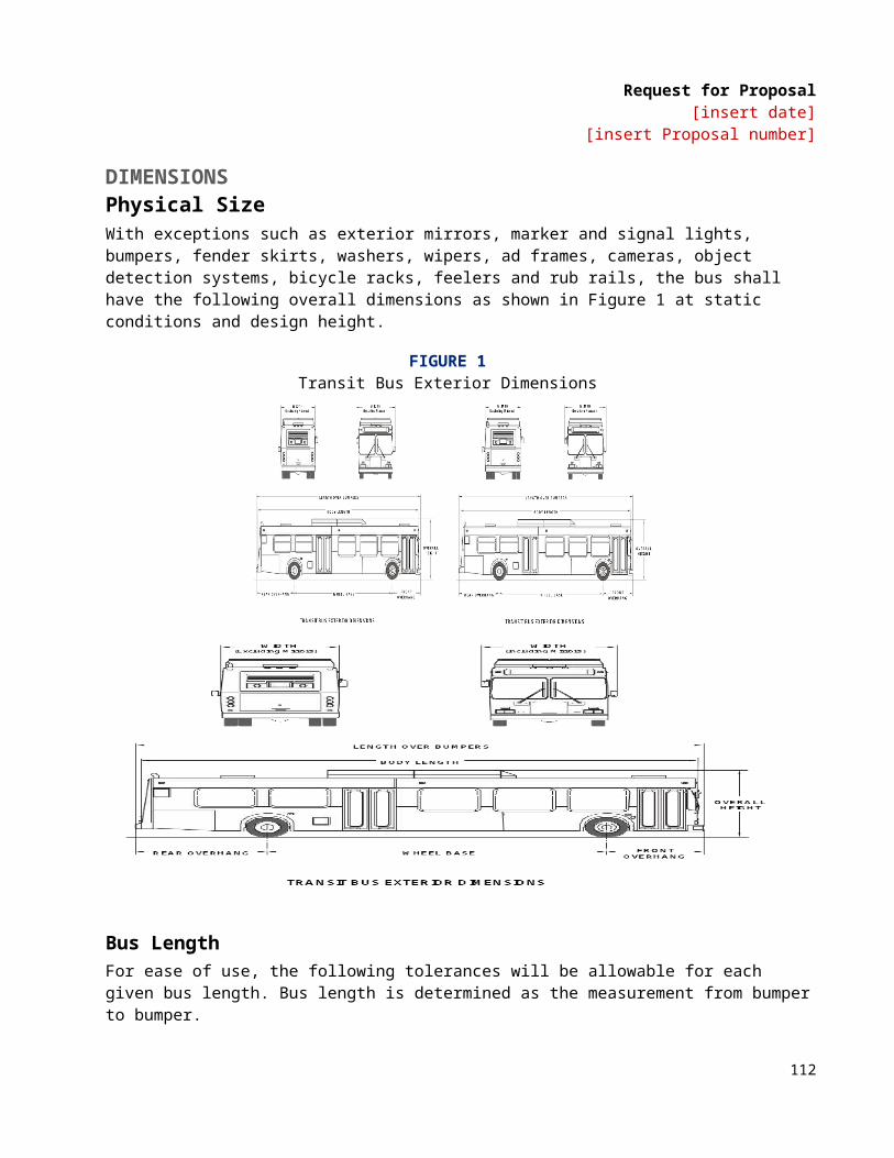
Request for Proposal[insert date]
[insert Proposal number]
ALTERNATIVEAir or hydraulic brakes.
DEFAULTNo automatic traction control. ALTERNATIVEAutomatic Traction Control Microprocessor controlled automatic traction control (ATC) shall be provided.
TS 35.3 Friction MaterialThe brake linings shall be made of non-asbestos material. In order to aid maintenance personnel in determining extent of wear, a provision such as a scribe line or chamfer indicating the thickness at which replacement becomes necessary shall be provided on each brake lining. The complete brake lining wear indicator shall be clearly visible from the hoist or pit without removing backing plates.
ALTERNATIVERemote brake wear indicator.
TS 35.4 Hubs and DrumsReplaceable wheel bearing seals shall run on replaceable wear surfaces or be of an integral wear surface sealed design. Wheel bearing and hub seals and unitized hub assemblies shall not leak or weep lubricant when operating on the design operating profile for the duration of the initial manufacturer’s warranty.
DEFAULTDrum BrakesThe bus shall be equipped with brake drums. Brake drums shall allow machining for oversized linings per manufacturers specifications.
ALTERNATIVEDisc Brakes on Front AxleThe bus shall be equipped with brake drums on the rear axle and disc brakes on the front axle. The brake drums shall allow machining for oversize linings per manufacturer’s specifications, and brake discs shall allow machining of each side of the disc to obtain smooth surfaces per manufacturer’s specifications.
ALTERNATIVEDisc Brakes on All AxlesThe bus shall be equipped with disc brakes on all axles, and the brake discs shall allow machining of each side of the disc to obtain smooth surfaces per manufacturer’s specifications.
114
Request for Proposal[insert date]
[insert Proposal number]
The brake system material and design shall be selected to absorb and dissipate heat quickly so that the heat generated during braking operation does not glaze brake linings.
TS 35.5 Parking/Emergency Brake DEFAULTAir BrakesThe parking brake shall be a spring-operated system, actuated by a valve that exhausts compressed air to apply the brakes. The parking brake may be manually enabled when the air pressure is at the operating level per FMVSS 121.
ALTERNATIVEEmergency BrakeAn emergency brake release shall be provided to release the brakes in the event of automatic emergency brake application. The driver shall be able to manually depress and hold down the emergency brake release valve to release the brakes and maneuver the bus to safety. Once the driver releases the emergency brake release valve, the brakes shall engage to hold the bus in place.
ALTERNATIVEHydraulic BrakesIf the bus is equipped with hydraulic brakes, the braking system must comply with FMVSS 105, including both service and parking brake features.
TS 36. InterlocksTS 36.1 Passenger Door InterlocksTo prevent opening mid and rear passenger doors while the bus is in motion, a speed sensor shall be integrated with the door controls to prevent the mid/rear doors from being enabled or opened unless the bus speed is less than 2 mph.
To preclude movement of the bus, an accelerator interlock shall lock the accelerator in the closed position, and a brake interlock shall engage the service brake system to stop movement of the bus when the driver’s door control is moved to a mid/rear door enable or open position, or a mid or rear door panel is opened more than 3 in. from the fully closed position (as measured at the leading edge of the door panel). The interlock engagement shall bring the bus to a smooth stop and shall be capable of holding a fully loaded bus on a 6 percent grade, with the engine at idle and the transmission in gear, until the interlocks are released. These interlock functions shall be active whenever the vehicle Master Run Switch is in any run position.
All door systems employing brake and accelerator interlocks shall be supplied with supporting failure mode effects analysis (FEMA) documentation, which demonstrates that failure modes are of a failsafe type, thereby never allowing the possibility of release of interlock while an interlocked door is in and unsecured condition, unless the door master switch has been actuated to intentionally release the interlocks.
DEFAULTNon-adjustable brake interlock regulator.
115
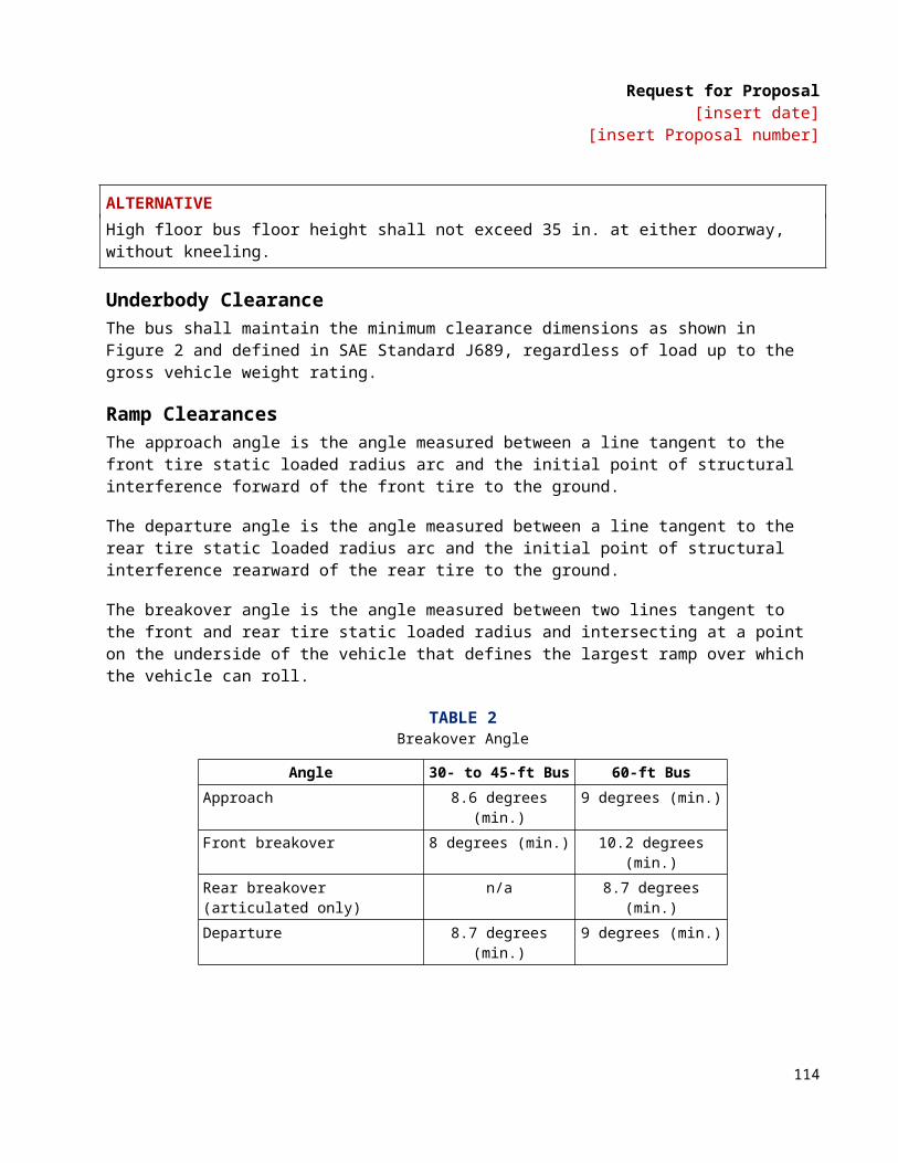
Request for Proposal[insert date]
[insert Proposal number]
ALTERNATIVEBraking effort adjustable with hand tools.
DEFAULTNo requirements for accelerator and brake interlocks whenever front doors are open.
ALTERNATIVERequiring Accelerator Interlock Whenever Front Doors Are OpenAn accelerator interlock shall lock the accelerator in the closed position, and a brake interlock shall engage the service brake system to stop movement of the bus whenever front doors are open.
TS 37. Pneumatic System TS 37.1 General The bus air system shall operate the air-powered accessories and the braking system with reserve capacity. New buses shall not leak down more than 5 psi over a 15-minute period of time as indicated on the dash gauge.
Provision shall be made to apply shop air to the bus air systems. A quick disconnect fitting shall be easily accessible and located in the engine compartment and near the front bumper area for towing. Retained caps shall be installed to protect fitting against dirt and moisture when not in use. Air for the compressor shall be filtered. The air system shall be protected per FMVSS 121.
TS 37.2 Air Compressor DEFAULTThe engine-driven air compressor shall be sized to charge the air system from 40 psi to the governor cut-off pressure in less than 4 minutes while not exceeding the fast idle speed setting of the engine.
ALTERNATIVEThe electrically driven air compressor shall be sized to charge the air system from 40 psi to the governor cut-off pressure in less than 4 minutes while not exceeding the fast idle speed setting of the engine.
TS 37.3 Air Lines and Fittings Air lines, except necessary flexible lines, shall conform to the installation and material requirements of SAE Standard J1149 for copper tubing with standard, brass, flared or ball sleeve fittings, or SAE Standard J844 for nylon tubing if not subject to temperatures over 200 oF. The air on the delivery side of the compressor where it enters nylon housing shall not be above the maximum limits as stated in SAE J844. Nylon tubing shall be installed in accordance with the following color-coding standards:
• Green: Indicates primary brakes and supply.• Red: Indicates secondary brakes.• Brown: Indicates parking brake• Yellow: Indicates compressor governor signal.• Black: Indicates accessories.
116
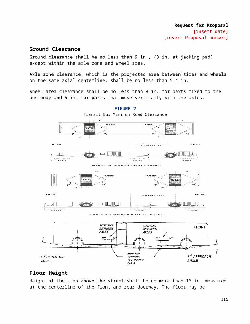
Request for Proposal[insert date]
[insert Proposal number]
Line supports shall prevent movement, flexing, tension, strain and vibration. Copper lines shall be supported to prevent the lines from touching one another or any component of the bus. To the extent practicable and before installation, the lines shall be pre-bent on a fixture that prevents tube flattening or excessive local strain. Copper lines shall be bent only once at any point, including pre-bending and installation. Rigid lines shall be supported at no more than 5-ft intervals. Nylon lines may be grouped and shall be supported at 30 in. intervals or less.
The compressor discharge line between powerplant and body-mounted equipment shall be flexible convoluted copper or stainless steel line, or may be flexible Teflon hose with a braided stainless steel jacket. Other lines necessary to maintain system reliability shall be flexible Teflon hose with a braided stainless steel jacket. End fittings shall be standard SAE or JIC brass or steel, flanged, swivel-type fittings. Flexible hoses shall be as short as practicable and individually supported. They shall not touch one another or any part of the bus except for the supporting grommets. Flexible lines shall be supported at 2-ft intervals or less.
Air lines shall be clean before installation and shall be installed to minimize air leaks. All air lines shall be routed to prevent water traps to the extent possible. Grommets or insulated clamps shall protect the air lines at all points where they pass through understructure components.
TS 37.4 Air Reservoirs All air reservoirs shall meet the requirements of FMVSS Standard 121 and SAE Standard J10 and shall be equipped with drain plugs and guarded or flush type drain valves. Major structural members shall protect these valves and any automatic moisture ejector valves from road hazards. Reservoirs shall be sloped toward the drain valve. All air reservoirs shall have drain valves that discharge below floor level with lines routed to eliminate the possibility of water traps and/or freezing in the drain line.
TS 37.5 Air System Dryer An air dryer shall prevent accumulation of moisture and oil in the air system. The air dryer system shall include one or more replaceable desiccant cartridges.
DEFAULTNo requirements for additional oil separator provision.
ALTERNATIVERequirement for Additional Oil Separator ProvisionA provision shall be included to collect/remove oil from the air system to prevent affecting function and/or damaging pneumatic system components.
ALTERNATIVEThe air system shall be equipped with an air dryer located before the no. 1 air tank and as far from the compressor as possible to allow air to cool prior to entering the air dryer.
ELECTRICAL, ELECTRONIC AND DATA COMMUNICATION SYSTEMSTS 38. Overview The electrical system will consist of vehicle battery systems and components that generate, distribute and store power throughout the vehicle. (e.g., generator, voltage regulator, wiring, relays, and connectors).
117
Request for Proposal[insert date]
[insert Proposal number]
Electronic devices are individual systems and components that process and store data, integrate electronic information or perform other specific functions.
The data communication system consists of the bi-directional communications networks that electronic devices use to share data with other electronic devices and systems. Communication networks are essential to integrating electronic functions, both onboard the vehicle and off.
Information level systems that require vehicle information for their operations or provide information shall adhere to J1939 data standard.
Data communications systems are divided into three levels to reflect the use of multiple data networks:
• Drivetrain level: Components related to the drivetrain including the propulsion system components (engine, transmission and hybrid units), and anti-lock braking system (ABS), which may include traction control.
• Information level: Components whose primary function is the collection, control or display of data that is not necessary to the safe drivability of the vehicle (i.e., the vehicle will continue to operate when those functions are inoperable). These components typically consist of those required for automatic vehicle location (AVL) systems, destination signs, fare boxes, passenger counters, radio systems, automated voice and signage systems, video surveillance and similar components.
• Multiplex level: Electrical or electronic devices controlled through input/output signals such as discrete, analog and serial data information (i.e., on/off switch inputs, relay or relay control outputs). Multiplexing is used to control components not typically found on the drivetrain or information levels, such as lights; wheelchair lifts; doors; heating, ventilation and air conditioning (HVAC) systems; and gateway devices.
FIGURE 5Data Communications Systems Levels
Information level
Multiplex level
Drivetrain level
TS 38.1 Modular DesignDesign of the electrical, electronic and data communication systems shall be modular so that each electronic device, apparatus panel, or wiring bundle is easily separable from its interconnect by means of connectors.
Powerplant wiring shall be an independent wiring harness. Replacement of the engine compartment wiring harness(es) shall not require pulling wires through any bulkhead or removing any terminals from the wires.
118
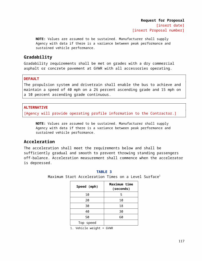
Request for Proposal[insert date]
[insert Proposal number]
TS 39. Environmental and Mounting RequirementsThe electrical system and its electronic components shall be capable of operating in the area of the vehicle in which they will be installed, as recommended in SAE J1455.
Electrical and electronic equipment shall not be located in an environment that will reduce the performance or shorten the life of the component or electrical system when operating within the design operating profile. As a recommendation, no vehicle component shall generate, or be affected by, electromagnetic interference or radio frequency interference (EMI/RFI) that can disturb the performance of electrical/electronic equipment as defined in SAE J1113 and UNECE Council Directive 95/54 (R 10).
The Agency shall follow recommendations from bus manufacturers and subsystem Suppliers regarding methods to prevent damage from voltage spikes generated from welding, jump starts, shorts, etc.
TS 39.1 Hardware Mounting The mounting of the hardware shall not be used to provide the sole source ground, and all hardware shall be isolated from potential EMI/RFI, as referenced in SAE J1113.
All electrical/electronic hardware mounted in the interior of the vehicle shall be inaccessible to passengers and hidden from view unless intended to be viewed. The hardware shall be mounted in such a manner as to protect it from splash or spray.
All electrical/electronic hardware mounted on the exterior of the vehicle that is not designed to be installed in an exposed environment shall be mounted in a sealed enclosure.
All electrical/electronic hardware and its mounting shall comply with the shock and vibration requirements of SAE J1455.
TS 40. General Electrical RequirementsTS 40.1 Batteries TS 40.1.1 Low-Voltage Batteries (24V)DEFAULTFour Group 31 Maintenance-Free BatteriesFour Group 31 Series deep cycling maintenance-free battery units shall be provided. Each battery shall have a minimum of 700 cold cranking amps. Each battery shall have a purchase date no more than one year from the date of release for shipment to the Agency.
ALTERNATIVETwo 8D Battery UnitsTwo 8D battery units conforming to SAE Standard J537 shall be provided. Each battery shall have a minimum of 1150 cold cranking amps. Each battery shall have a purchase date no more than 120 days from the date of release, and shall be fully maintained prior to shipment to the Agency. The battery compartment must be well-ventilated to prevent hydrogen buildup while protecting the compartment from road spray, water intrusion and de-icing chemicals.
119
Request for Proposal[insert date]
[insert Proposal number]
ALTERNATIVETwo 8D Maintenance-Free BatteriesEach battery shall have a purchase date no more than 120 days from date of release, and shall be fully maintained prior to shipment to the Agency. Battery compartment must be well ventilated to prevent hydrogen buildup while protecting the compartment from road spray, water intrusion and de-icing chemicals.
DEFAULTSame Size Terminal EndsPositive and negative terminal ends shall be the same size.
ALTERNATIVEDifferent Size Terminal EndsPositive and negative terminal ends shall be different sizes.
ALTERNATIVECapacitor Start SystemA capacitor start system will be provided to assist with starting the bus. This system will be isolated from the regular starting system to prevent the capacitors from draining during regular operation or long periods of down time.
TS 40.1.2 Battery CablesThe battery terminal ends and cables shall be color-coded with red for the primary positive, black for negative and another color for any intermediate voltage cables. Positive and negative battery cables shall not cross each other if at all possible, be flexible and sufficiently long to reach the batteries with the tray in the extended position without stretching or pulling on any connection and shall not lie directly on top of the batteries. Except as interrupted by the master battery switch, battery and starter wiring shall be continuous cables with connections secured by bolted terminals and shall conform to specification requirements of SAE Standard J1127 – Type SGT, SGX or GXL and SAE Recommended Practice J541.
2100 strand 4/0 cable or greater recommended.
ALTERNATIVEColor code each voltage.
TS 40.1.3 Jump Start DEFAULTNo requirements for jump-start connector.
ALTERNATIVEJump-Start ConnectorA jump-start connector, red for 24V and blue for 12V, shall be provided in the engine compartment, equipped with dust cap and adequately protected from moisture, dirt and debris.
120
Request for Proposal[insert date]
[insert Proposal number]
ALTERNATIVEJump-Start ConnectorA jump-start connector is located next to the battery disconnect switch.
TS 40.1.4 Battery CompartmentThe battery compartment shall prevent accumulation of snow, ice and debris on top of the batteries and shall be vented and self-draining. It shall be accessible only from the outside of the vehicle. All components within the battery compartment, and the compartment itself, shall be protected from damage or corrosion from the electrolyte. The inside surface of the battery compartment’s access door shall be electrically insulated, as required, to prevent the battery terminals from shorting on the door if the door is damaged in an accident or if a battery comes loose.
The vehicle shall be equipped with a 12VDC and 24VDC quick disconnect switch(es). The battery compartment door shall conveniently accommodate operation of the 12VDC and 24VDC quick disconnect switch(es).
The battery quick disconnect access door shall be identified with a decal. The decal size shall not be less than 3.5 × 5 in. (8.89 × 12.7 cm).
The battery hold-down bracket shall be constructed of a non-metallic material (plastic or fiberglass).
This access door shall not require any special locking devices to gain access to the switch, and it shall be accessible without removing or lifting the panel. The door shall be flush-fitting and incorporate a spring tensioner or equal to retain the door in a closed position when not in use.
The batteries shall be securely mounted on a stainless steel or equivalent tray that can accommodate the size and weight of the batteries. The battery tray shall pull out easily and properly support the batteries while they are being serviced. The tray shall allow each battery cell to be easily serviced and filled. A locking device shall retain the battery tray to the stowed position.
If not located in the engine compartment, the same fire-resistant properties must apply to the battery compartment. No sparking devices should be located within the battery box.
TS 40.1.5 Auxiliary Electronic Power SupplyIf required, gel-pack, or any form of sealed (non-venting) batteries used for auxiliary power are allowed to be mounted on the interior of the vehicle if they are contained in an enclosed, non-airtight compartment and accessible only to maintenance personnel. This compartment shall contain a warning label prohibiting the use of lead-acid batteries.
TS 40.1.6 Master Battery SwitchA single master switch shall be provided near the battery compartment for the disconnecting of all battery positives (12V and 24V), except for safety devices such as the fire suppression system and other systems as specified. The location of the master battery switch shall be clearly identified on the exterior access panel, be accessible in less than 10 seconds for deactivation and prevent corrosion from fumes and battery acid when the batteries are washed off or are in normal service.
121
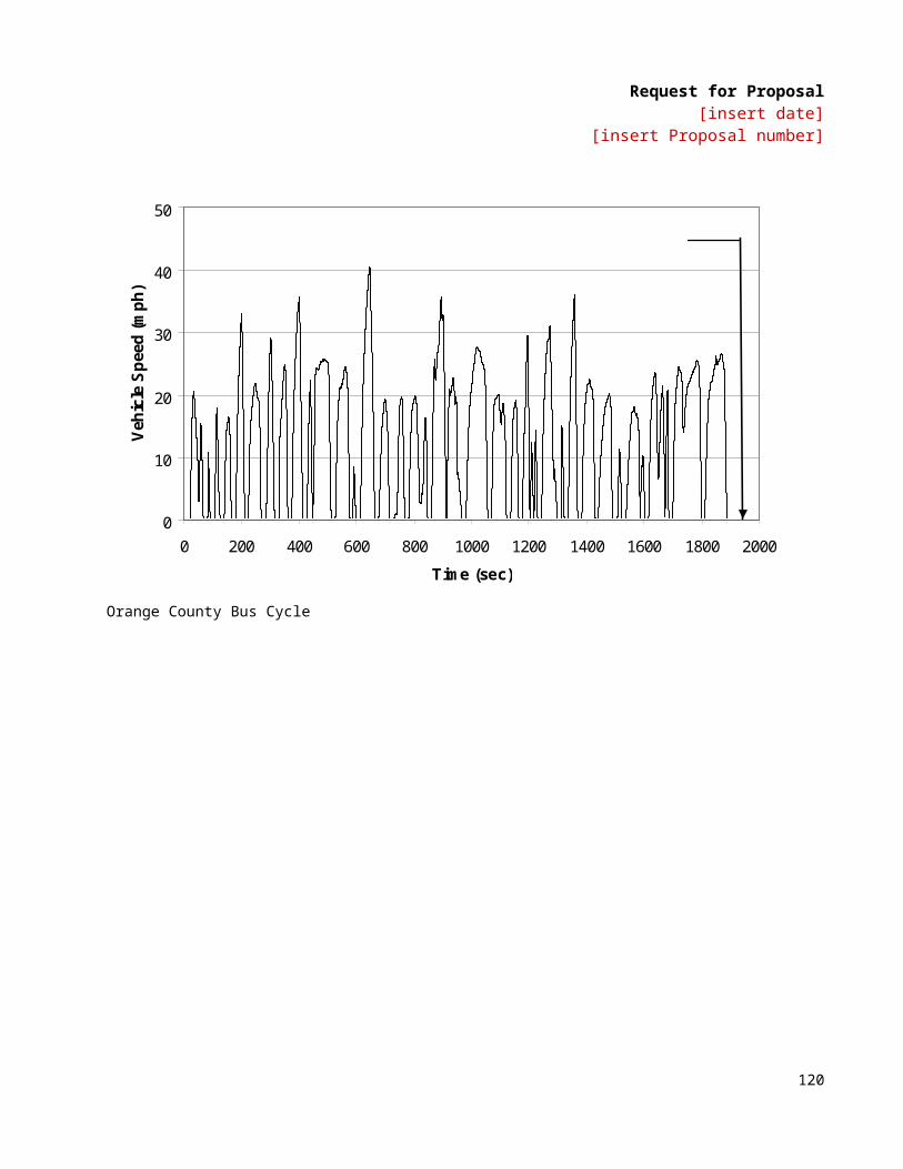
Request for Proposal[insert date]
[insert Proposal number]
Turning the master switch off with the powerplant operating shall shut off the engine and shall not damage any component of the electrical system. The master switch shall be capable of carrying and interrupting the total circuit load.
DEFAULTSingle SwitchThe batteries shall be equipped with a single switch for disconnecting both 12V and 24V power.
ALTERNATIVESeparate SwitchesThe batteries shall be equipped with separate switches for disconnecting 12V and 24V power.
ALTERNATIVESolenoid Battery Cutoff A multiplex system activated battery cutoff solenoid to disconnect battery except critical items.
ALTERNATIVEMaster Battery Switch Access Panel Door Lock Lock should be accessed with a standard square key.
TS 40.1.7 Low-Voltage Generation and DistributionThe low-voltage generating system shall maintain the charge on fully charged batteries, except when the vehicle is at standard idle with a total low voltage generator load exceeding 70 percent of the low voltage generator nameplate rating.
Voltage monitoring and over-voltage output protection (recommended at 32V) shall be provided.
Dedicated power and ground shall be provided as specified by the component or system manufacturer. Cabling to the equipment must be sized to supply the current requirements with no greater than a 5 percent volt drop across the length of the cable.
TS 40.1.8 Circuit ProtectionAll branch circuits, except battery-to-starting motor and battery-to-generator/alternator circuits, shall be protected by current-limiting devices such as circuit breakers, fuses or solid state devices sized to the requirements of the circuit. Electronic circuit protection for the cranking motor shall be provided to prevent engaging of the motor for more than 30 seconds at a time to prevent overheating. The circuit breakers or fuses shall be easily accessible for authorized personnel. Fuses shall be used only where it can be demonstrated that circuit breakers are not practicable. This requirement applies to in-line fuses supplied by either the Contractor or a Supplier. Fuse holders shall be constructed to be rugged and waterproof. All manual reset circuit breakers critical to the operation of the bus shall be mounted in a location convenient to the Agency mechanic with visible indication of open circuits. The Agency shall consider the application of automatic reset circuit breakers on a case-by-case basis. The Contractor shall show all in-line fuses in the final harness drawings. Any manually resettable circuit breakers shall provide a visible indication of open circuits. Any manually resettable circuit breakers shall provide a visible indication of open circuits.
122

Request for Proposal[insert date]
[insert Proposal number]
Circuit breakers or fuses shall be sized to a minimum of 15 percent larger than the total circuit load. The current rating for the wire used for each circuit must exceed the size of the circuit protection being used.
TS 40.2 Grounds The battery shall be grounded to the vehicle chassis/frame at one location only, as close to the batteries as possible. When using a chassis ground system, the chassis shall be grounded to the frame in multiple locations, evenly distributed throughout the vehicle to eliminate ground loops. No more than four ground ring/spade terminal connections shall be made per ground stud. Electronic equipment requiring an isolated ground to the battery (i.e., electronic ground) shall not be grounded through the chassis.
TS 40.3 Low Voltage/Low Current Wiring and Terminals All power and ground wiring shall conform to specification requirements of SAE Recommended Practice J1127, J1128 and J1292. Double insulation shall be maintained as close to the junction box, electrical compartment or terminals as possible. The requirement for double insulation shall be met by wrapping the harness with plastic electrical tape or by sheathing all wires and harnesses with non-conductive, rigid or flexible conduit.
Wiring shall be grouped, numbered and/or color-coded. Wiring harnesses shall not contain wires of different voltage classes unless all wires within the harness are insulated for the highest voltage present in the harness. Kinking, grounding at multiple points, stretching, and exceeding minimum bend radius shall be prevented.
Strain-relief fittings shall be provided at all points where wiring enters electrical compartments. Grommets or other protective material shall be installed at points where wiring penetrates metal structures outside of electrical enclosures. Wiring supports shall be protective and non-conductive at areas of wire contact and shall not be damaged by heat, water, solvents or chafing.
To the extent practicable, wiring shall not be located in environmentally exposed locations under the vehicle. Wiring and electrical equipment necessarily located under the vehicle shall be insulated from water, heat, corrosion and mechanical damage. Where feasible, front to rear electrical harnesses should be installed above the window line of the vehicle.
All wiring harnesses over 5 ft long and containing at least five wires shall include 10 percent (minimum one wire) excess wires for spares. This requirement for spare wires does not apply to data links and communication cables. Wiring harness length shall allow end terminals to be replaced twice without pulling, stretching or replacing the wire. Terminals shall be crimped to the wiring according to the connector manufacturer’s recommendations for techniques and tools. All cable connectors shall be locking type, keyed and sealed, unless enclosed in watertight cabinets or vehicle interior. Pins shall be removable, crimp contact type, of the correct size and rating for the wire being terminated. Unused pin positions shall be sealed with sealing plugs. Adjacent connectors shall either use different inserts or different insert orientations to prevent incorrect connections.
Terminals shall be crimped, corrosion-resistant and full ring type or interlocking lugs with insulating ferrules. When using pressure type screw terminal strips, only stranded wire shall be used. Insulation clearance shall ensure that wires have a minimum of “visible clearance” and a maximum of two times the conductor diameter or 1/16 in., whichever is less. When using shielded or coaxial cable, upon stripping of the insulation, the metallic braid shall be free from frayed strands that can penetrate the insulation of the inner wires.
123
Request for Proposal[insert date]
[insert Proposal number]
Ultra-sonic and T-splices may be used with 7 AWG or smaller wire. When a T-splice is used, it shall meet these additional requirements:
• It shall include a mechanical clamp in addition to solder on the splice. • The wire shall support no mechanical load in the area of the splice. • The wire shall be supported to prevent flexing.
All splicing shall be staggered in the harness so that no two splices are positioned in the same location within the harness.
Wiring located in the engine compartment shall be routed away from high-heat sources or shielded and/or insulated from temperatures exceeding the wiring and connector operating requirements.
The instrument panel and wiring shall be easily accessible for service from the driver’s seat or top of the panel. The instrument panel shall be separately removable and replaceable without damaging the instrument panel or gauges. Wiring shall have sufficient length and be routed to permit service without stretching or chafing the wires.
TS 40.4 Electrical ComponentsAll electrical components, including switches, relays, flashers and circuit breakers, shall be heavy-duty designs with either a successful history of application in heavy-duty vehicles or design specifications for an equivalent environment.
All electric motors shall be heavy-duty brushless type where practical, and have a continuous duty rating of no less than 40,000 hours (except cranking motors, washer pumps and wiper motors). All electric motors shall be easily accessible for servicing.
TS 40.5 Electrical CompartmentsAll relays, controllers, flashers, circuit breakers and other electrical components shall be mounted in easily accessible electrical compartments. All compartments exposed to the outside environment shall be corrosion-resistant and sealed. The components and their functions in each electrical compartment shall be identified and their location permanently recorded on a drawing attached to the inside of the access panel or door. The drawing shall be protected from oil, grease, fuel and abrasion.
The front compartment shall be completely serviceable from the driver’s seat, vestibule or from the outside. “Rear start and run” controls shall be mounted in an accessible location in the engine compartment and shall be protected from the environment.
TS 41. General Electronic RequirementsIf an electronic component has an internal real-time clock, it shall provide its own battery backup to monitor time when battery power is disconnected, and/or it may be updated by a network component. If an electronic component has an hour meter, it shall record accumulated service time without relying on battery backup.
All electronic component Suppliers shall ensure that their equipment is self-protecting in the event of shorts in the cabling, and also in over-voltage (over 32V DC on a 24V DC nominal voltage rating with a maximum of 50V DC) and reverse polarity conditions. If an electronic component is required to interface with other components, it shall not require external pull-up and/or pull-down resistors. Where this is not possible, the use of a pull-up or pull-down resistor shall be limited as much as possible and easily accessible and labeled.
124

Request for Proposal[insert date]
[insert Proposal number]
TS 41.1 Wiring and TerminalsKinking, grounding at multiple points, stretching and reducing the bend radius below the manufacturer’s recommended minimum shall not be permitted.
TS 41.1.1 Discrete I/O (Inputs/Outputs)All wiring to I/O devices, either at the harness level or individual wires, shall be labeled, stamped or color-coded in a fashion that allows unique identification at a spacing not exceeding 4 in. Wiring for each I/O device shall be bundled together. If the I/O terminals are the same voltages, then jumpers may be used to connect the common nodes of each I/O terminal.
TS 41.1.2 ShieldingAll wiring that requires shielding shall meet the following minimum requirements. A shield shall be generated by connecting to a ground, which is sourced from a power distribution bus bar or chassis. A shield shall be connected at one location only, typically at one end of the cable. However certain standards or special requirements, such as SAE J1939 or RF applications, have separate shielding techniques that also shall be used as applicable.
NOTE: A shield grounded at both end forms a ground loop, which can cause intermittent control or faults.
When using shielded or coaxial cable, upon stripping of the insulation, the metallic braid shall be free from frayed strands, which can penetrate the insulation of the inner wires. To prevent the introduction of noise, the shield shall not be connected to the common side of a logic circuit.
TS 41.1.3 CommunicationsThe data network cabling shall be selected and installed according to the selected protocol requirements. The physical layer of all network communication systems shall not be used for any purpose other than communication between the system components, unless provided for in the network specifications.
Communications networks that use power line carriers (e.g., data modulated on a 24V-power line) shall meet the most stringent applicable wiring and terminal specifications.
TS 41.1.4 Radio Frequency (RF)RF components, such as radios, video devices, cameras, global positioning systems (GPS), etc., shall use coaxial cable to carry the signal. All RF systems require special design consideration for losses along the cable. Connectors shall be minimized, since each connector and crimp has a loss that will attribute to attenuation of the signal. Cabling should allow for the removal of antennas or attached electronics without removing the installed cable between them. If this cannot be done, then a conduit of sufficient size shall be provided for ease of attachment of antenna and cable assembly. The corresponding component vendors shall be consulted for proper application of equipment, including installation of cables.
TS 41.1.5 AudioCabling used for microphone level and line level signals shall be 22 AWG minimum with shielded twisted pair. Cabling used for amplifier level signals shall be 18 AWG minimum.
125

Request for Proposal[insert date]
[insert Proposal number]
TS 42. MultiplexingTS 42.1 GeneralThe primary purpose of the multiplexing system is control of components necessary to operate the vehicle. This is accomplished by processing information from input devices and controlling output devices through the use of an internal logic program.
Versatility and future expansion shall be provided for by expandable system architecture. The multiplex system shall be capable of accepting new inputs and outputs through the addition of new modules and/or the utilization of existing spare inputs and outputs. All like components in the multiplex system shall be modular and interchangeable with self-diagnostic capabilities. The modules shall be easily accessible for troubleshooting electrical failures and performing system maintenance. Multiplex input/output modules shall use solid-state devices to provide extended service life and individual circuit protection.
DEFAULTTen percent of the total number of inputs and outputs, or at least one each for each voltage type utilized (0V, 12V, 24V), at each module location shall be designated as spares.
ALTERNATIVENo spares shall be designated.
TS 42.2 System ConfigurationMultiplexing may either be distributed or centralized. A distributed system shall process information on multiple control modules within the network. A centralized system shall process the information on a single control module. Either system shall consist of several modules connected to form a control network.
TS 42.2.1 I/O SignalsThe input/output for the multiplex system may contain three types of electrical signals: discrete, analog or serial data.
Discrete signals shall reflect the on/off status of switches, levers, limit switches, lights, etc. Analog signals shall reflect numerical data as represented by a voltage signal (0-12V, 10-24V, etc.) or current signal (4-20 mA). Both types of analog signals shall represent the status of variable devices such as rheostats, potentiometers, temperature probes, etc. Serial data signals shall reflect ASCII or alphanumeric data used in the communication between other on-board components.
TS 43. Data CommunicationsTS 43.1 GeneralAll data communication networks shall be either in accordance with a nationally recognized interface standard, such as those published by SAE, IEEE or ISO, or shall be published to the Agency with the following minimum information:
• Protocol requirements for all timing issues (bit, byte, packet, inter-packet timing, idle line timing, etc.) packet sizes, error checking and transport (bulk transfer of data to/from the device).
• Data definition requirements that ensure access to diagnostic information and performance characteristics.
126

Request for Proposal[insert date]
[insert Proposal number]
• The capability and procedures for uploading new application or configuration data.• Access to revision levels of data, application software and firmware.• The capability and procedures for uploading new firmware or application software.• Evidence that applicable data shall be broadcast to the network in an efficient manner such that the
overall network integrity is not compromised.
Any electronic vehicle components used on a network shall be conformance tested to the corresponding network standard.
TS 43.2 Drivetrain LevelDrivetrain components, consisting of the engine, transmission, retarder, anti-lock braking system and all other related components, shall be integrated and communicate fully with respect to vehicle operation with data using SAE Recommended Communications Protocols such as J1939 and/or J1708/J1587 with forward and backward compatibilities or other open protocols.
TS 43.2.1 Diagnostics, Fault Detection and Data AccessDrivetrain performance, maintenance and diagnostic data, and other electronic messages shall be formatted and transmitted on the communications networks.
The drivetrain level shall have the ability to record abnormal events in memory and provide diagnostic codes and other information to service personnel. At a minimum, this network level shall provide live/fail status, current hardware serial number, software/data revisions and uninterrupted timing functions.
TS 43.2.2 Programmability (Software)The drivetrain level components shall be programmable by the Agency with limitations as specified by the sub-system Supplier.
TS 43.3 Multiplex LevelTS 43.3.1 Data AccessAt a minimum, information shall be made available via a communication port on the multiplex system. The location of the communication port shall be easily accessible. A hardware gateway and/or wireless communications system are options if requested by the Agency. The communication port(s) shall be located as specified by the Agency.
TS 43.3.2 Diagnostics and Fault DetectionThe multiplex system shall have a proven method of determining its status (system health and input/output status) and detecting either active (online) or inactive (offline) faults through the use of on-board visual/audible indicators.
In addition to the indicators, the system shall employ an advanced diagnostic and fault detection system, which shall be accessible via either a personal computer or a handheld unit. Either unit shall have the ability to check logic function. The diagnostic data can be incorporated into the information level network or the central data access system.
DEFAULTNo requirement for mock-up board.
127
Request for Proposal[insert date]
[insert Proposal number]
ALTERNATIVEProvide Mock-Up BoardA mock-up board, where key components of the multiplexing system are replicated on a functional model, shall be provided as a tool for diagnostic, design verification and training purposes. If required, the mock-up board should priced separately in the Pricing Schedule.
TS 43.3.3 Programmability (Software)The multiplex system shall have security provisions to protect its software from unwanted changes. This shall be achieved through any or all of the following procedures:
• password protection• limited distribution of the configuration software• limited access to the programming tools required to change the software• hardware protection that prevents undesired changes to the software
Provisions for programming the multiplex system shall be possible through a PC or laptop. The multiplex system shall have proper revision control to ensure that the hardware and software are identical on each vehicle equipped with the system. Revision control shall be provided by all of the following:
• hardware component identification where labels are included on all multiplex hardware to identify components
• hardware series identification where all multiplex hardware displays the current hardware serial number and firmware revision employed by the module
• software revision identification where all copies of the software in service displays the most recent revision number
• a method of determining which version of the software is currently in use in the multiplex system
DEFAULTRevision control labels shall be electronic.
ALTERNATIVERevision control labels shall be physically located near the programming port.
TS 43.4 Electronic Noise ControlElectrical and electronic sub-systems and components on all buses shall not emit electromagnetic radiation that will interfere with on-board systems, components or equipment, telephone service, radio or TV reception or violate regulations of the Federal Communications Commission.
Electrical and electronic sub-systems on the coaches shall not be affected by external sources of RFI/EMI. This includes, but is not limited to, radio and TV transmission, portable electronic devices including computers in the vicinity of or onboard the buses, ac or dc power lines and RFI/EMI emissions from other vehicles.
128

Request for Proposal[insert date]
[insert Proposal number]
DRIVER PROVISIONS, CONTROLS AND INSTRUMENTATIONTS 44. Driver’s Area ControlsTS 44.1 GeneralIn general when designing the driver’s area, it is recommended that SAE J833, “Human Physical Dimensions,” be used.
Switches and controls shall be divided into basic groups and assigned to specific areas, in conformance with SAE Recommended Practice J680, Revised 1988, “Location and Operation of Instruments and Controls in Motor Truck Cabs,” and be essentially within the hand reach envelope described in SAE Recommended Practice J287, “Driver Hand Control Reach.”
TS 44.2 Glare The driver’s work area shall be designed to minimize glare to the extent possible. Objects within and adjacent to this area shall be matte black or dark gray in color wherever possible to reduce the reflection of light onto the windshield. The use of polished metal and light-colored surfaces within and adjacent to the driver’s area shall be avoided.
TS 44.3 Visors/Sun ShadesDEFAULTFront and Side Sun Shade/VisorAdjustable sun visor(s) shall be provided for the driver’s windshield and the driver’s side window. Visors shall be shaped to minimize light leakage between the visor and windshield pillars. Visors shall store out of the way and shall not obstruct airflow from the climate control system or interfere with other equipment, such as the radio handset or the destination control. Deployment of the visors shall not restrict vision of the rearview mirrors. Visor adjustments shall be made easily by hand with positive locking and releasing devices and shall not be subject to damage by over-tightening. Sun visor construction and materials shall be strong enough to resist breakage during adjustments. Visors may be transparent, but shall not allow a visible light transmittance in excess of 10 percent. Visors, when deployed, shall be effective in the driver’s field of view at angles more than 5 degrees above the horizontal.
ALTERNATIVEDriver’s Window SunscreensAn adjustable roller type sunscreen shall be provided over the driver’s windshield and/or the driver’s side window. The sunscreen shall be capable of being lowered to the midpoint of the driver’s window. When deployed, the screen shall be secure, stable and shall not rattle, sway or intrude into the driver’s field of view due to the motion of the coach or as a result of air movement. Once lowered, the screen shall remain in the lowered position until returned to the stowed position by the driver. Sunscreen shall be shaped to minimize light leakage between the visor and windshield pillars to the extent possible
TS 44.4 Driver’s ControlsFrequently used controls must be in easily accessible locations. These include the door control, kneel control, windshield wiper/washer controls, ramp, and lift and run switch. Any switches and controls necessary for the safe operation of the bus shall be conveniently located and shall provide for ease of operation. They shall be identifiable by shape, touch and permanent markings. Controls also shall be located so that passengers may not easily tamper with control settings.
129
Request for Proposal[insert date]
[insert Proposal number]
All panel-mounted switches and controls shall be marked with easily read identifiers. Graphic symbols shall conform to SAE Recommended Practice J2402, “Road Vehicles – Symbols For Controls, Indicators, and Tell Tales,” where available and applicable. Color of switches and controls shall be dark with contrasting typography or symbols.
Mechanical switches and controls shall be replaceable, and the wiring at these controls shall be serviceable from a convenient location. Switches, controls and instruments shall be dust- and water-resistant.
TS 44.5 Normal Bus Operation Instrumentation and ControlsThe following list identifies bus controls used to operate the bus. These controls are either frequently used or critical to the operation of the bus. They shall be located within easy reach of the operator. The operator shall not be required to stand or turn to view or actuate these controls unless specified otherwise.
Systems or components monitored by onboard diagnostics system shall be displayed in clear view of the operator and provide visual and/or audible indicators. The intensity of indicators shall permit easy determination of on/off status in bright sunlight but shall not cause a distraction or visibility problem at night. All indicators shall be illuminated using backlighting.
The indicator panel shall be located in Area 1 or Area 5, within easy view of the operator instrument panel. All indicators shall have a method of momentarily testing their operation. The audible alarm shall be tamper-resistant and shall have an outlet level between 80 and 83 dBA when measured at the location of the operator’s ear.
On-board displays visible to the operator shall be limited to indicating the status of those functions described herein that are necessary for the operation of the bus. All other indicators needed for diagnostics and their related interface hardware shall be concealed and protected from unauthorized access. Table 3 represents instruments and alarms. The intent of the overall physical layout of the indicators shall be in a logical grouping of systems and severity nature of the fault.
Consideration shall be provided for future additions of spare indicators as the capability of onboard diagnostic systems improves. Blank spaces shall contain LEDs.
TABLE 6Transit Bus Instruments and Alarms
Device Description Location Function Visual/ AudibleMaster run switch Rotary, four-position detent Side console Master control for bus, off, day run,
night run and clearance ID lights
Engine start, front Approved momentary switch Side console Activates engine starter motor
Engine start, rear Approved momentary switch Engine
compartment Activates engine starter motor
Engine run, rear Three-position toggle switch Engine
compartmentPermits running engine from rear start, normal front run position and off Amber light
Drive selector Touch panel switch Side console Provides selection of propulsion:
forward, reverse and neutral Gear selection
130

Request for Proposal[insert date]
[insert Proposal number]
TABLE 6Transit Bus Instruments and Alarms
Device Description Location Function Visual/ Audible
HVAC Switch or switches to control HVAC Side console
Permits selection of passenger ventilation: off, cool, heat, low fan, high fan or full auto with on/off only
Driver’s ventilation Rotary, three-position detent Side console or
Dash left wingPermits supplemental ventilation: fan off, low or high
Defroster fan Rotary, three-position detent Side console or Dash left wing
Permits defroster: fan off, low, medium or high
Defroster temperature Variable position Side console or
Dash left wingAdjusts defroster water flow and temperature
Windshield wiper
One-variable rotary position operating both wipers Dash left wing Variable speed control of left and right
windshield wipers
Windshield washer Push button Dash left wing Activates windshield washers
Dash panel lights
Rotary rheostat or stepping switch
Side Console or Dash left wing
Provides adjustment for light intensity in night run position
Interior lights Three-position switch Side console Selects mode of passenger compartment lighting: off, on, normal
Fast idle Two-position switch Side console Selects high idle speed of engine
WC ramp/kneel enable Two-position switch1 Side console or
Dash right wingPermits operation of ramp and kneel operations at each door remote panel Amber light
Front door ramp/kneel enable
Two-position keyed switch1Front door remote or Dash right wing
Permits ramp and kneel activation from front door area, key required1 Amber light
Front door ramp
Three-position momentary switch
Right side of steering wheel Permits deploy and stow of front ramp Red light
Front kneel Three-position momentary switch
Front door remote
Permits kneeling activation and raise and normal at front door remote location
Amber or red dash indicator. Ext alarm and Amber light
Rear door ramp/kneel enable
Two-position keyed switch1 Rear door remote
Permits ramp and kneel activation from rear door area, key required1 Red light
Rear door ramp
Three-position momentary switch
Rear door remote Permits deploy and stow of rear ramp
Rear kneel Three-position momentary switch
Rear door remote
Permits kneeling activation and raise and normal at rear door remote location
Silent alarm Recessed push button, NO and NC contacts momentary Side console
Activates emergency radio alarm at dispatch and permits covert microphone and/or enables destination sign emergency message
Video system event switch
Momentary on/off momentary switch with plastic guard
Side console Triggers event equipment, triggers event light on dash Amber light
131
Request for Proposal[insert date]
[insert Proposal number]
TABLE 6Transit Bus Instruments and Alarms
Device Description Location Function Visual/ AudibleLeft remote mirror Four-position toggle type Side console Permits two-axis adjustment of left
exterior mirror
Right remote mirror Four-position toggle type Side console Permits two-axis adjustment of right
exterior mirror
Mirror heater Switch or temperature activated Side console Permits heating of outside mirrors
when required
Passenger door control
Five-position handle type detent or two momentary push buttons
Side console, forward
Permits open/close control of front and rear passenger doors Red light
Rear door override
Two-position switch in approved location
Side console, forward
Allows driver to override activation of rear door passenger tape switches
Engine shutdown override
Momentary switch with operation protection Side console Permits driver to override auto engine
shutdown
Hazard flashers Two-position switch Side console or
Dash right wing Activates emergency flashers Two green lights
Fire suppression
Red push button with protective cover
Dash left wing or dash center
Permits driver to override and manually discharge fire suppression system
Red light
Mobile data terminal
Mobile data terminal coach operator interface panel
Above right dash wing
Facilitates driver interaction with communication system and master log-on
LCD display with visual status and text messages
Farebox interface
Farebox coach operator interface panel Near farebox Facilitates driver interaction with
farebox system LCD display
Destination sign interface
Destination sign interface panel
in approved location
Facilitates driver interaction with destination sign system, manual entry LCD display
Turn signalsMomentary push button (two required) raised from other switches
Left foot panel Activates left and right turn signalsTwo green lights and optional audible indicator
PA manual Momentary push button In approved location
Permits driver to manually activate public address microphone
Low profilemicrophone
Low-profile discreteMounting Steering column
Permits driver to make announcements with both hands on the wheel and focusing on road conditions
High beam Detented push button In approved location
Permits driver to toggle between low and high beam Blue light
Parking brake Pneumatic PPV Side console or
Dash left wingPermits driver to apply and release parking brake Red light
Park brake release Pneumatic PPV
Vertical side of the side console or dash center
Permits driver to push and hold to release brakes
132
Request for Proposal[insert date]
[insert Proposal number]
TABLE 6Transit Bus Instruments and Alarms
Device Description Location Function Visual/ Audible
Hill holder Two-position momentary switch Side console Applies brakes to prevent bus from
rolling
Remote engine speed
Rotary rheostat Engine compartment
Permits technician to raise and lower engine RPM from engine compartment
Master door/interlock Multi-pole toggle, detented Out of operator’s
reachPermits driver override to disable door and brake/throttle interlock Red light
Warning interlocks deactivated
Red indicator light Dash panel center
Illuminates to warn drive that interlocks have been deactivated. Red light
Retarder disable Multi-pole switch detented
Within reach of Operator or approved location
Permits driver override to disable brake retardation/regeneration Red light
Alarm acknowledge
Push button momentary Approved location
Permits driver to acknowledge alarm condition
Rear door passenger sensor disable
Multi-pole toggle, detented
In sign compartment or Driver’s barrier compartment
Permits driver to override rear door passenger sensing system
Indicator/alarm test button
Momentary switch or programming1
Dash center panel
Permits driver to activate test of sentry, indicators and audible alarms
All visuals and audibles
Auxiliary power 110-volt power receptacle Approved
locationProperty to specify what function to supply
Speedometer
Speedometer, odometer, and diagnostic capability, 5-mile increments
Dash center panel
Visual indication of speed and distance traveled, accumulated vehicle mileage, fault condition display
Visual
Air pressure gauge
Primary and secondary,5 psi increments
Dash center panel
Visual indication of primary and secondary air systems Red light and buzzer
Fire detection Coach operator display Property specific
or dash centerIndication of fire detection activation by zone/location Buzzer and red light
Door obstruction Sensing of door obstruction Dash center Indication of rear door sensitive edge
activation Red light and buzzer
Door ajar Door not properly closed Property specific or dash center
Indication of rear door not properly closed
Buzzer or alarm and red light
Low system air pressure
Sensing low primary and secondary air tank pressure Dash center Indication of low air system pressure Buzzer and red light
Methane detection function
Detection of system integrity Property specific or dash center Detects system failure No start condition,
amber light
Methane detection
Indication of 20% LED emergency light (LEL)
Property specific or dash center Detects levels of methane Flashing red at 20%
LEL
133

Request for Proposal[insert date]
[insert Proposal number]
TABLE 6Transit Bus Instruments and Alarms
Device Description Location Function Visual/ AudibleMethane detection Indication of 50% LEL Property specific
or dash center Detects levels of methane Solid red at 50% LEL
Engine coolant indicator
Low coolant indicator may be supplied as audible alert and visual and/or text message
Within driver’s sight Detects low coolant condition Amber light
Hot engine indicator
Coolant temperature indicator may be supplied as audible alert and visual and/or text message
Within driver’s sight
Detects hot engine condition and initiates time delay shutdown Red light
Low engine oil pressure indicator
Engine oil pressure indicator may be supplied as audible alert and visual and/or text message
Within driver’s sight
Detects low engine oil pressure condition and initiates time-delayed shutdown
Red light
ABS indicator Detects system status Dash center Displays system failure Amber light
HVAC indicator Detects system status Dash center Displays system failure Amber or red light
Charging system indicator (12/24 V)
Detect charging system status Dash center
Detects no charge condition and optionally detects battery high, low, imbalance, no charge condition, and initiates time-delayed shutdown
Red light flashing or solid based on condition
Bike rack deployed indicator
Detects bike rack position Dash center Indication of bike rack not being in fully stowed position Amber or red light
Fuel tank level
Analog gauge, graduated based on fuel type Dash center Indication of fuel tank level/pressure
DEF gauge Level Indicator Center dash Displays level of DEF tank and indicates with warning light when low Red light
Active regeneration Detects Status Dash center Indication of electric regeneration Amber or red light
Turntable Detects Status Dash Center Warning indication for hinge lockingAudible and amber warning and red light if locked
Turntable Interlock momentary switch Side console Momentarily release interlock brakes due to overangled condition
1. Indicate area by drawing. Break up switches control from indicator lights.
TS 44.6 Driver Foot ControlsAccelerator and brake pedals shall be designed for ankle motion. Foot surfaces of the pedals shall be faced with wear-resistant, nonskid, replaceable material.
TS 44.6.1 Pedal AngleThe vertical angle of the accelerator and brake pedals shall be determined from a horizontal plane regardless of the slope of the cab floor. The accelerator and brake pedals shall be positioned at an angle of 37 to 50
134
Request for Proposal[insert date]
[insert Proposal number]
degrees at the point of initiation of contact and extend downward to an angle of 10 to 18 degrees at full throttle.
The location of the brake and accelerator pedals shall be determined by the manufacturer, based on space needs, visibility, lower edge of windshield, and vertical H-point.
TS 44.6.2 Pedal Dimensions and PositionThe floor-mounted accelerator pedal shall be 10 to 12 in. long and 3 to 4 in. wide. Clearance around the pedal must allow for no interference precluding operation.
DEFAULT1 to 2 in. Between Brake and Accelerator PedalsThe accelerator and brake pedals shall be positioned such that the spacing between them, measured at the heel of the pedals, is between 1 and 2 in. Both pedals should be located approximately on the same plane coincident to the surface of the pedals.
TS 44.7 Brake and Accelerator PedalsDEFAULTBrake PedalNon-adjustable brake pedal.
ALTERNATIVEAdjustable Brake and Accelerator PedalsBoth pedals shall be adjustable forward and rearward a minimum of 3 in. The adjustment shall be made by use of a dash-mounted toggle or rocker switch. The switch shall be clearly labeled to identify it as pedal adjustment and shall be within easy reach of the driver. Pedal adjustment shall be enabled only when the bus is stationary and the parking brake engaged.
TS 44.8 Driver Foot SwitchesFloor-Mounted Foot Control PlatformThe angle of the turn signal platform shall be determined from a horizontal plane, regardless of the slope of the cab floor. The turn signal platform shall be angled at a minimum of 10 degrees and a maximum of 37 degrees. It shall be located no closer to the seat front than the heel point of the accelerator pedal.
Turn Signal ControlsTurn signal controls shall be floor-mounted, foot-controlled, water-resistant, heavy-duty, momentary contact switches.
ALTERNATIVE Adjustable turn signal platform.
135
Request for Proposal[insert date]
[insert Proposal number]
DEFAULTFoot Switch ControlThe control switches for the turn signals shall be mounted on an inclined, floor-mounted stainless steel enclosure or metal plate mounted to an incline integrated into the driver’s platform, located to the left of the steering column. The location and design of this enclosure shall be such that foot room for the operator is not impeded. The inclined mounting surface shall be skid-resistant. All other signals, including high beam and public address system shall be in approved location.
The foot switches shall be UL-listed, heavy-duty type, of a rugged, corrosion-resistant metal construction. The foot switches for the directionals shall be momentary type, while those for the PA system and the high beam shall be latching type. The spacing of the switches shall be such that inadvertent simultaneous deflection of switches is prevented. ALTERNATIVEOther Floor-Mounted ControlsThe following may be floor mounted, momentary or latching, as identified by the Agency.
• hazard• silent alarm• PA system
ALTERNATIVESteering wheel mounted (self-canceling)
TS 45. Driver’s AmenitiesTS 45.1 Coat HangerDEFAULTCoat HangerA suitable hanger shall be installed in a convenient, approved location for the driver’s coat.
ALTERNATIVECoat HookA hook and loop shall be provided to secure the driver’s coat.
TS 45.2 Drink HolderDEFAULTNo drink holder.
136
Request for Proposal[insert date]
[insert Proposal number]
ALTERNATIVEDrink HolderA device shall be provided to securely hold the driver’s drink container, which may vary widely in diameter. It must be mounted within easy reach of the driver and must have sufficient vertical clearance for easy removal of the container. When the container is in the device, the driver’s view of the road must not be obstructed, and leakage from the container must not fall on any switches, gauges or controls.
TS 45.3 Storage BoxDEFAULTStorage BoxAn enclosed driver storage area shall be provided with a positive latching door and/or lock. The minimum size is 2750 cubic in.
ALTERNATIVENo storage box.
TS 46. Windshield Wipers and WashersTS 46.1 Windshield WipersThe bus shall be equipped with a windshield wiper for each half of the windshield. At 60 mph, no more than 10 percent of the wiped area shall be lost due to windshield wiper lift. For two- piece windshields, both wipers shall park along the center edges of the windshield glass. For single-piece windshields, wipers shall park along the bottom edge of the windshield. Windshield wiper motors and mechanisms shall be easily accessible for repairs or service. The fastener that secures the wiper arm to the drive mechanism shall be corrosion-resistant.
DEFAULTSingle-control, electric two-speed intermittent wiper.
ALTERNATIVEWiper Powered by Compressed Air If powered by air, exhaust from the wiper motors shall be muffled or piped under the floor of the bus.
DEFAULTSingle control for air-operated system.
ALTERNATIVEDual controls for air-operated system.
137

Request for Proposal[insert date]
[insert Proposal number]
ALTERNATIVEIntermittent Wiper with Variable ControlA variable-speed feature shall be provided to allow adjustment of wiper speed for each side of the windshield between approximately five (5) and twenty-five (25) cycles per minute.
ALTERNATIVEMultiple wiper systems and controls.
ALTERNATIVENon-Synchronized Wipers For non-synchronized wipers, separate controls for each side shall be supplied.
TS 46.2 Windshield WashersThe windshield washer system, when used with the wipers, shall deposit washing fluid evenly and completely wet the entire wiped area.
The windshield washer system shall have a minimum 3-gallon reservoir, located for easy refilling from outside of the bus. Reservoir pumps, lines and fittings shall be corrosion-resistant and must include a means to determine fluid level.
TS 47. Driver’s SeatFIGURE 6
Driver’s Seat
138
Head rest
Seat back
Arm rest
Seat belt
Seat pan cushion Seat base
Seat back lumbar support

Request for Proposal[insert date]
[insert Proposal number]
TS 47.1 DimensionsThe driver’s seat shall be comfortable and adjustable so that people ranging in size from a 95th-percentile male to a 5th-percentile female may operate the bus.
TS 47.1.1 Seat Pan Cushion LengthMeasurement shall be from the front edge of the seat pan to the rear at its intersection with the seat back. The adjustment of the seat pan length shall be no less than 16.5 in. at its minimum length and no more than 20.5 in. at its maximum length.
SP 12.1.1 Seat Pan Cushion HeightDEFAULT DimensionsMeasurement shall be from the cab floor to the top of the level seat at its center midpoint. The seat shall adjust in height from a minimum of 14 in., with a minimum 6 in. vertical range of adjustment.
ALTERNATIVE H-PointThe reference point for seat height shall be determined by establishing the H-point.
TS 47.1.2 Seat Pan Cushion SlopeMeasurement is the slope of the plane created by connecting the two high points of the seat, one at the rear of the seat at its intersection with the seat back and the other at the front of the seat just before it waterfalls downward at the edge. The slope can be measured using an inclinometer and shall be stated in degrees of incline relative to the horizontal plane (0 degrees). The seat pan shall adjust in its slope from no less than plus 12 degrees (rearward “bucket seat” incline), to no less than minus 5 degrees (forward slope).
TS 47.1.3 Seat Base Fore/Aft AdjustmentMeasurement is the horizontal distance from the heel point to the front edge of the seat. The minimum and maximum distances shall be measured from the front edge of the seat when it is adjusted to its minimum seat pan depth (approximately 15 in.). On all low-floor buses, the seat-base shall travel horizontally a minimum of 9 in. It shall adjust no closer to the heel point than 6 in. On all high-floor buses, the seat base shall travel a minimum of 9 in. and adjust no closer to the heel-point than 6 in.
TS 47.1.4 Seat Pan Cushion Width Measurement is the horizontal distance across the seat cushion. The seat pan cushion shall be 17 to 21 in. across at the front edge of the seat cushion and 20 to 23 in. across at the side bolsters.
TS 47.1.5 Seat SuspensionThe driver’s seat shall be appropriately dampened to support a minimum weight of 380 lbs. The suspension shall be capable of dampening adjustment in both directions.
Rubber snubbers shall be provided to prevent metal-to-metal contact.
139
Request for Proposal[insert date]
[insert Proposal number]
TS 47.1.6 Seat Back WidthMeasurement is the distance between the outermost points of the front of the seat back, at or near its midpoint in height. The seat back width shall be no less than 19 in. Seat back will include dual recliner gears on both sides of the seat.
HeightDEFAULTStandard height seat back.
TS 47.1.7 HeadrestsDEFAULTAdjustable headrest.
ALTERNATIVENo headrest.
TS 47.1.8 Seat Back Lumbar SupportMeasurement is from the bottom of the seat back at its intersection with the seat pan to the top of the lumbar cushioning. The seat back shall provide adjustable depth lumbar back support with three individual operating lumbar cells within a minimum range of 7 to 11 in.
TS 47.1.9 Seat Back Angle AdjustmentThe seat back angle shall be measured relative to a level seat pan, where 90 degrees is the upright position and 90 degrees-plus represents the amount of recline.
The seat back shall adjust in angle from a minimum of no more than 90 degrees (upright) to at least 105 degrees (reclined), with infinite adjustment in between.
TS 47.2 Seat Belt The belt assembly should be an auto-locking retractor (ALR). All seat belts should be stored in automatic retractors. The belts shall be mounted to the seat frame so that the driver may adjust the seat without resetting the seat belt.
The seat and seat belt assemblies as installed in the bus shall withstand static horizontal forces as required in FMVSS 207 and 210.
DEFAULTLap seat belt only.
DEFAULTSeatbelt webbing shall be black in color.
140

Request for Proposal[insert date]
[insert Proposal number]
ALTERNATIVELap and Shoulder (Three-Point) Seat BeltSeat belts shall be provided across the driver’s lap and diagonally across the driver’s chest. The driver shall be able to use both belts by connecting a single buckle on the right side of the seat cushion. 3-pt seatbelts must be emergency locking retractor (ELR) in design.
ALTERNATIVEAdjustable-height D-ring.
ALTERNATIVEAll seatbelt assemblies shall come equipped with a warning switch device to remind operators to buckle up.
ALTERNATIVEOrange three-point seatbelt webbing.
Lap Belt LengthDEFAULT72 in. The lap belt assembly shall be a minimum of 72 in. in length.
ALTERNATIVE72 in. with ExtensionThe lap belt assembly shall be 72 in. in length with an 8-in. extension
TS 47.3 Adjustable ArmrestDEFAULTNo armrests.
ALTERNATIVEOne armrest, right side.
ALTERNATIVEOne armrest, left side.
ALTERNATIVETwo armrests.
141
Request for Proposal[insert date]
[insert Proposal number]
TS 47.4 Seat Control LocationsWhile seated, the driver shall be able to make seat adjustments by hand without complexity, excessive effort or being pinched. Adjustment mechanisms shall hold the adjustments and shall not be subject to inadvertent changes.
TS 47.5 Seat Structure and MaterialsCushionsCushions shall be fully padded with at least 3 in. of materials in the seating areas at the bottom and back.
Cushion MaterialsDEFAULTClosed-cell polyurethane (FMVSS 302).
ALTERNATIVEFoam and fabric that meets FTA Docket 90A.
TS 47.6 PedestalDEFAULTPowder-coated steel.
ALTERNATIVEStainless steel.
TS 47.7 Seat OptionsALTERNATIVE
• heated seat• seat alarm• fabric options• seat air vent• side bolsters adjustments• LiquiCell
TS 47.8 Mirrors TS 47.8.1 Exterior MirrorsThe bus shall be equipped with a corrosion-resistant, outside rearview mirrors mounted with stable supports to minimize vibration. Mirrors shall be firmly attached to the bus to minimize vibration and to prevent loss of adjustment with a breakaway mounting system. Mirrors shall permit the driver to view the roadway along the sides of the bus, including the rear wheels. Mirrors should be positioned to prevent blind spots.
Mirrors shall retract or fold sufficiently to allow bus washing operations but avoid contact with windshield.
142
Request for Proposal[insert date]
[insert Proposal number]
ALTERNATIVEBreakaway mounting system.
ALTERNATIVESpring loaded mirror heads auto return.
DEFAULTFlat Mirrors on Both SidesThe bus shall be equipped with two flat outside mirrors, each with not less than 50 sq in. of reflective surface. The mirrors shall be located so as to provide the driver a view to the rear along both sides of the bus and shall be adjustable both in the horizontal and vertical directions to view the rearward scene. The roadside rearview mirror shall be positioned so that the driver’s line of sight is not obstructed.
ALTERNATIVECombination of flat and convex mirrors referred to as transit-specific.
ALTERNATIVECombination of Mirrors and CCTV CamerasThe bus shall be equipped with a combination of mirrors and CCTV cameras. The configuration will be transit-Agency specific.
Curbside MirrorsThe curbside rearview mirror shall be mounted so that its lower edge is no less than 76 in. above the street surface. A lower mount may be required due to requested mirror configuration requests
DEFAULTRemote Adjustment of Curbside MirrorThe driver shall be able to adjust the curbside mirror remotely while seated in the driving position. The control for remote positioning of the mirror shall be a single switch or device.
ALTERNATIVEStandard mirror, not heated, not remote adjustment.
ALTERNATIVEHeated and Remote MirrorsThe heaters shall be energized whenever the driver’s heater and/or defroster is activated or activated independently.
Street-Side Mirrors DEFAULTStandard mirror, not heated, not remote adjustment.
143

Request for Proposal[insert date]
[insert Proposal number]
ALTERNATIVERemote Adjustment of Curbside MirrorThe driver shall be able to adjust the street-side mirror remotely while seated in the driving position. The control for remote positioning of the mirror shall be a single switch or device.
ALTERNATIVEHeated Street-Side MirrorsThe street-side mirrors shall have heaters that energize whenever the driver’s heater and/or defroster is activated, or can be activated independently.
ALTERNATIVEMirrors with integrated turn signal, one side.
ALTERNATIVEMirrors with integrated turn signal, both sides.
ALTERNATIVEMirrors with external mounted turn signal, one side.
ALTERNATIVEMirrors with external mounted turn signal, both sides.
TS 47.8.2 Interior MirrorsMirrors shall be provided for the driver to observe passengers throughout the bus without leaving the seat and without shoulder movement. The driver shall be able to observe passengers in the front/entrance and rear/exit areas, anywhere in the aisle, and in the rear seats.
WINDOWSTS 48. General ALTERNATIVE[Use with 30-ft length] A minimum of 6000 sq in. of window area, including operator and door windows, shall be required on each side of the standard configuration bus.
ALTERNATIVE[Use with 35-ft length] A minimum of 8000 sq in. of window area, including operator and door windows, shall be required on each side of the standard configuration bus.
144

Request for Proposal[insert date]
[insert Proposal number]
ALTERNATIVE[Use with 40-ft length] A minimum of 10,000 sq in. of window area, including operator and door windows, shall be required on each side of the standard configuration bus.
ALTERNATIVE[Use with 45-ft length] A minimum of 12,000 sq in. of window area, including operator and door windows, shall be required on each side of the standard configuration bus.
ALTERNATIVE[Use with 60-ft length] A minimum of 16,000 sq in. of window area, including operator and door windows, shall be required on each side of the standard configuration bus.
TS 49. Windshield The windshield shall permit an operator’s field of view as referenced in SAE Recommended Practice J1050. The vertically upward view shall be a minimum of 14 degrees, measured above the horizontal and excluding any shaded band. The vertically downward view shall permit detection of an object 3½ ft high no more than 2 ft in front of the bus. The horizontal view shall be a minimum of 90 degrees above the line of sight. Any binocular obscuration due to a center divider may be ignored when determining the 90-degree requirement, provided that the divider does not exceed a 3-degree angle in the operator’s field of view. Windshield pillars shall not exceed 10 degrees of binocular obscuration. The windshield shall be designed and installed to minimize external glare as well as reflections from inside the bus.
The windshield shall be easily replaceable by removing zip-locks from the windshield retaining moldings. Bonded-in-place windshields shall not be used. Winglets may be bonded.
TS 49.1 GlazingThe windshield glazing material shall have a ¼ in. nominal thickness laminated safety glass conforming to the requirements of ANSI Z26.1 Test Grouping 1A and the Recommended Practices defined in SAE J673.
DEFAULT Shaded BandThe upper portion of the windshield above the driver’s field of view shall have a dark, shaded band with a minimum luminous transmittance of 5 percent when tested in accordance to ASTM D-1003.
ALTERNATIVEPartial band required to allow view for camera and mirror viewing.
ALTERNATIVENo band required.
DEFAULT Two-piece windshield.
145
Request for Proposal[insert date]
[insert Proposal number]
ALTERNATIVEOne-piece windshield.
TS 50. Driver’s Side Window The driver’s side window shall be the sliding type, requiring only the rear half of sash to latch upon closing, and shall open sufficiently to permit the seated operator to easily adjust the street-side outside rearview mirror. When in an open position, the window shall not rattle or close during braking. This window section shall slide in tracks or channels designed to last the service life of the bus. The operator’s side window shall not be bonded in place and shall be easily replaceable. The glazing material shall have a single-density tint.
The driver’s view, perpendicular through operator’s side window glazing, should extend a minimum of 33 in. (840 mm) to the rear of the heel point on the accelerator, and in any case must accommodate a 95th percentile male operator. The view through the glazing at the front of the assembly should begin not more than 26 in. (560 mm) above the operator’s floor to ensure visibility of an under-mounted convex mirror. Driver’s window construction shall maximize ability for full opening of the window.
The driver’s side window glazing material shall have a ¼ in. nominal thickness laminated safety glass conforming with the requirements of ANSI Z26.1-1996 Test Grouping 2 and the Recommended Practices defined in SAE J673.
The design shall prevent sections from freezing closed in the winter. Light transmittance shall be 75 percent on the glass area below 53 in. from the operator platform floor. On the top fixed over bottom slider configuration, the top fixed area above 53 in. may have a maximum 5 percent light transmittance.
DEFAULTStandard Driver’s Side Window, Traditional Frame[Agency to choose from the following options.]
• full slider• egress• non-egress
• top fixed over bottom slider• egress• non-egress
ALTERNATIVEHidden Frame (Flush “Euro-look”) Driver’s Side Window[Agency to choose from the following options.]
• full slider• egress• non-egress
• top fixed over bottom slider• egress• non-egress
146
Request for Proposal[insert date]
[insert Proposal number]
ALTERNATIVEQuick Change Operator’s Side Window Glazing in the window assembly shall be replaced without removing the window from its installed position on the bus or manipulation of the rubber molding surrounding the glazing. The glazing shall be held in place mechanically by a formed metal extruded ring constructed to last the life of the vehicle.
ALTERNATIVEStandard Driver’s Side Window, Traditional Frame[Agency to choose from the following options.]
• full slider• egress• non-egress
• top fixed over bottom slider• egress• non-egress
TS 51. Side Windows TS 51.1 Configuration Side windows shall not be bonded in place, but shall be easily replaceable without disturbing adjacent windows and shall be mounted so that flexing or vibration from engine operation or normal road excitation is not apparent. All aluminum and steel material will be treated to prevent corrosion.
TS 51.2 Emergency Exit (Egress) ConfigurationDEFAULTMinimum EgressAll side windows shall be fixed in position, except as necessary to meet the emergency escape requirements.
ALTERNATIVEMaximum EgressEvery window shall be capable of being made an egress window.
DEFAULTStandard Passenger Side Window Configurations[Agency to choose from the following options.]
• traditional frame• full fixed• openable windows with inward-opening transom panels• openable windows with sliding transom panels• openable windows with a fixed transom panel and sliding lower panels• openable windows with full-height sliding panels
• hidden frame (flush “Euro-look”)• full fixed• openable windows with inward-opening transom panels.
147
Request for Proposal[insert date]
[insert Proposal number]
ALTERNATIVEQuick Change Passenger Side WindowsGlazing in the window assembly shall be replaced without removing the window from its installed position on the bus or manipulation of the rubber molding surrounding the glazing. The glazing shall be held in place mechanically by a formed metal extruded ring constructed to last the life of the vehicle.
DEFAULTTraditional Frame[Agency to choose from the following options.]
• full fixed• openable windows with inward-opening transom panels• openable windows with sliding transom panels• openable windows with a fixed transom panel and sliding lower panels• openable windows with full-height sliding panels
ALTERNATIVEHidden Frame (Seamless)[Agency to choose from the following options.]
• full fixed• openable windows with inward-opening transom panels
TS 51.3 Configuration ALTERNATIVE Fixed Side WindowsAll side windows shall be fixed in position, except as necessary to meet the emergency escape requirements.
ALTERNATIVEOperable Side Window ConfigurationsAll side windows, except windows in passenger doors and those smaller than 500 sq in., shall have window panels that are operable by passengers. Operable window panels shall be equipped with latches that secure the window in the fully open and fully closed positions.
[Agency shall then specify one of the following options.]
ALTERNATIVE Operable Windows with Inward-Opening Transom Panels (Fixed Bottom, Tip-In Top) Each operable side window shall incorporate an upper transom portion. The transom shall be between 25 and 35 percent of the total window area. The lower portion of the window shall be fixed. The transom portion shall be hinged along the lower edge and open inward.
148
Request for Proposal[insert date]
[insert Proposal number]
ALTERNATIVE Operable Windows with Sliding Transom PanelsEach operable side window shall incorporate an upper transom portion. The transom shall be between 25 and 35 percent of the total window area. The lower portion of the window shall be fixed. The transom portion shall consist of two horizontally sliding panels.
ALTERNATIVE Operable Windows with a Fixed Transom Panel and Sliding Lower Panels (Top Fixed, Bottom Slide)Each operable side window shall incorporate an upper transom side. The transom shall be between 25 and 35 percent of the total window area. The transom portion of the window shall be fixed. The lower portion shall consist of two horizontally sliding panels.
ALTERNATIVE Operable Windows with Operable Transom Panel and Sliding Lower PanelsEach operable side window shall incorporate an upper transom portion. The transom shall be between 25 and 35 percent of the total window area. The transom portion of the window shall be hinged at lower edge and open inward. The lower portion shall consist of two horizontally sliding panels.
ALTERNATIVE Operable Windows with Full-Height Sliding PanelsEach operable side window shall consist of two full-height horizontally sliding panels. All side windows shall be easily replaceable without disturbing adjacent windows and shall be mounted so that flexing or vibration from engine operation or normal road excitation is not apparent. The windows shall be designed and constructed to enable a mechanic to remove and replace one window in less than 15 minutes.
TS 51.4 MaterialsDEFAULTSafety Glass Glazing PanelsSide windows glazing material shall have a minimum of 3/16 in. nominal thickness tempered safety glass. The material shall conform to the requirements of ANSI Z26.1-1996 Test Grouping 2 and the Recommended Practices defined in SAE J673.
ALTERNATIVE Polycarbonate Glazing Panels Side window glazing material shall have a minimum 3/16 in. nominal thickness. The material shall conform with the requirements of ANSI Z26.1-1996, “Standard for Type AS-5 Safety Glazing Materials,” except for Test Number 17, which shall subject the specimens to 100 cycles with less than 4 percent hazing and 500 cycles with less than 12 percent hazing. Windows shall be polycarbonate sheet with an abrasion resistant coating on both sides of the window.
149
Request for Proposal[insert date]
[insert Proposal number]
ALTERNATIVE Acrylic Glazing Panels Side window glazing material shall have a minimum of 3/16 in. nominal thickness. The material shall conform with the requirements of ANSI Z26.1-1996, “Standard for Type AS-5 Safety Glazing Materials,” except for Test Number 17, which shall subject the specimens to 100 cycles with less than 4 percent hazing and 500 cycles with less than 12 percent hazing. Windows shall be cell cast acrylic sheet with an abrasion resistant coating on both sides of the window.
ALTERNATIVE Laminated Glazing Panels (Not Available on Hidden Frame [Seamless] Windows)Side windows glazing material shall have a minimum of 3/16 in. nominal thickness laminated safety glass. The material shall conform to applicable requirements of ANSI Z26.1-1996 and the Recommended Practices defined in SAE J673.
ALTERNATIVE Laminated and Tempered Safety Glazing with Anti-vandalism Polyester Sacrificial Film All glazing material that is aft of the standee line shall be equipped with 6 mm laminated polyester film. This material shall be easily installed and removed without the use of specialized tools. Polyester film shall adhere to the window and be resistant to peeling, curling and discoloration by ultraviolet rays. The film shall withstand normal cleaning operations.
ALTERNATIVE Anti-Vandalism Sacrificial Liner (“Quick Change”)All glazing material aft of the standee line shall be equipped with necessary bracketry, fasteners and clear acrylic liner that shall be easily removable in the event of vandalism. The acrylic liner shall be clear and shall have minimal effect on the transmittance of the underlying glazing. This material shall not be adversely affected by ultraviolet rays and shall withstand normal cleaning practices. The installation of the liner shall prevent clouding or fogging. This acrylic sacrificial liner must be replaced without removing the window from its installed position on the bus, without removing the tempered glazing from the sash, and without the removal or manipulation of the window assembly’s rubber molding.
Windows on the bus sides and in the rear door shall be tinted a neutral color, complementary to the bus exterior. The maximum solar energy transmittance shall not exceed 37 percent, as measured by ASTM E-424. Luminous transmittance shall be measured by ASTM D-1003. Windows over the destination signs shall not be tinted.
DEFAULT (LIGHT)55 percent luminous transmittance.
ALTERNATIVE (LIGHT)75 percent luminous transmittance.
150
Request for Proposal[insert date]
[insert Proposal number]
DEFAULT (DARK)27 percent luminous transmittance.
ALTERNATIVE Property to specify, but by no less than 12 percent.
DEFAULTSafety Glass Glazing PanelsSide windows glazing material shall have a minimum of 3/16 in. nominal thickness tempered safety glass. The material shall conform to the requirements of ANSI Z26.1 Test Grouping 2 and the Recommended Practices defined in SAE J673.
ALTERNATIVE Polycarbonate Glazing PanelsSide window glazing material shall have a minimum of 3/16 in. in. nominal thickness. The material shall conform to the requirements of ANSI Z26.1-1977, “Standard for Type AS-5 Safety Glazing Materials,” except for Test Number 17, which shall subject the specimens to 1000 cycles and the arithmetic mean of the percentages of light scattered shall not exceed 5 percent. Windows shall be polycarbonate sheet with an abrasion-resistant coating on both sides of the window.
ALTERNATIVE Acrylic Glazing PanelsSide window glazing material shall have a minimum of 3/16 in. in. nominal thickness. The material shall conform to the requirements of ANSI Z26.1-1977, “Standard for Type AS-5 Safety Glazing Materials,” except for Test Number 17, which shall subject the specimens to 1000 cycles and the arithmetic mean of the percentages of light scattered shall not exceed 5 percent. Windows shall be cell cast acrylic sheet with an abrasion-resistant coating on both sides of the window.
ALTERNATIVE Laminated Glazing Panels Side windows glazing material shall have a minimum of 3/16 in. in. nominal thickness laminated safety glass. The material shall conform to applicable requirements of ANSI Z26.1 and the Recommended Practices defined in SAE J673.
ALTERNATIVE Anti-Vandalism Polyester Sacrificial Film All glazing material that is aft of the standee line shall be equipped with 6 mm laminated polyester film. This material shall be easily installed and removed without the use of specialized tools. Polyester film shall adhere to the window and be resistant to peeling, curling and discoloration by ultraviolet rays. The film shall withstand normal cleaning operations.
151
Request for Proposal[insert date]
[insert Proposal number]
ALTERNATIVE Anti-Vandalism Sacrificial Liner (“Storm Window Type”)All glazing material aft of the standee line shall be equipped with necessary bracketry, fasteners and clear acrylic liner that shall be easily removable in the event of vandalism. The acrylic material shall be clear and shall have minimal effect the transmittance of the underlying glazing. This material shall not be adversely affected by ultraviolet rays and shall withstand normal cleaning practices. The installation of the liner shall prevent clouding or fogging. A mechanic shall be able to easily remove and replace the acrylic liner without the use of any specialized tools in 5 minutes or less.
Windows on the bus sides and in the rear door shall be tinted a neutral color, complementary to the bus exterior. The maximum solar energy transmittance shall not exceed 37 percent, as measured by ASTM E-424, and the luminous transmittance shall be no less than 16 percent, as measured by ASTM D-1003. Window at the destination/location sign shall not be tinted in the vicinity of the sign.
TS 51.5 Rear Window DEFAULTNo requirement for rear window.
ALTERNATIVE Rear Window Requirement[Note that requirement for a rear-mounted HVAC unit will preclude a rear window.] A rear window shall be provided. The rear window shall be glazed with same material (including anti-vandalism provision if required) and tint as side windows. The glazing shall be set in rubber channels or be push-out type to meet FMVSS 217. If push-out type, it shall be one-piece, rugged sash design, meeting specifications for side windows.
HEATING, VENTILATING AND AIR CONDITIONINGTS 52. Capacity and Performance The HVAC climate control system shall be capable of controlling the temperature and maintaining the humidity levels of the interior of the bus as defined in the following paragraphs.
DEFAULT HVAC equipped. [See below for configuration]
ALTERNATIVENo Requirements for CoolingAll requirements relevant to the HVAC cooling mode contained in this section, as well as throughout this specification, need not apply. All other requirements for heating and ventilation still apply.
DEFAULTAllow Either Roof- or Rear-Mounted HVAC UnitThe HVAC unit may either be roof or rear-mounted. [Note that a rear-mounted unit will preclude a rear window and that the term “roof-mounted unit” includes units mounted on top of or beneath the roof surface.]
152
Request for Proposal[insert date]
[insert Proposal number]
ALTERNATIVERequire Roof-Mounted HVAC UnitThe HVAC unit shall be roof-mounted. [Note that this includes units mounted on top of or beneath the roof surface.]
ALTERNATIVERequire Rear-Mounted HVAC UnitThe HVAC unit shall be rear-mounted.
ALTERNATIVERequire Under-Floor HVAC UnitThe HVAC unit shall be mounted under the floor.
ALTERNATIVERequire roof- and rear-mounted HVAC unit (articulated buses)
ALTERNATIVE (HYBRID BUSES)Fully AC high-voltage electric-driven A/C system with full hermetic AC compressor, condenser fan and evaporator blower motors.
ALTERNATIVE (DIESEL OR CNG BUSES)Fully AC high-voltage electric-driven A/C system with full hermetic AC compressor, condenser fan, evaporator blower motors and brushless AC generators.
ALTERNATIVEAC Shore Power ConnectionAccessibility and serviceability of preventative maintenance components shall be provided, minimizing the maintenance personnel needed to work on the roof of the bus.
With the bus running at the design operating profile with corresponding door opening cycle, and carrying a number of passengers equal to 150 percent of the seated load, the HVAC system shall control the average passenger compartment temperature within a range between 65 and 80 °F, while maintaining the relative humidity to a value of 50 percent or less. The system shall maintain these conditions while subjected to any outside ambient temperatures within a range of 10 to 95 °F and at any ambient relative humidity levels between 5 and 50 percent.
When the bus is operated in outside ambient temperatures of 95 to 115 °F, the interior temperature of the bus shall be permitted to rise 0.5° for each degree of exterior temperature in excess of 95 °F.
When bus is operated in outside ambient temperatures in the range of -10 to 10 °F, the interior temperature of the bus shall not fall below 55 °F while the bus is running on the design operating profile.
153

Request for Proposal[insert date]
[insert Proposal number]
System capacity testing, including pull-down/warm-up, stabilization and profile, shall be conducted in accordance to the APTA’s “Recommended Instrumentation and Performance Testing for Transit Bus Air Conditioning System.”
The recommended locations of temperature probes are only guidelines and may require slight modifications to address actual bus design. Care must be taken to avoid placement of sensing devices in the immediate path of an air duct outlet. In general, the locations are intended to accurately represent the interior passenger area.
Additional testing shall be performed as necessary to ensure compliance to performance requirements stated herein.
DEFAULTCapacity and Performance RequirementsThe air-conditioning portion of the HVAC system shall be capable of reducing the passenger compartment temperature from 110 to 90 °F in less than 20 minutes after engine start-up. Engine temperature shall be within the normal operating range at the time of start-up of the cool-down test, and the engine speed shall be limited to fast idle, which may be activated by a driver-controlled device. During the cool-down period, the refrigerant pressure shall not exceed safe high-side pressures, and the condenser discharge air temperature, measured 6 in. from the surface of the coil, shall be less than 45 °F above the condenser inlet air temperature. The appropriate solar load as recommended in the APTA “Recommended Instrumentation and Performance Testing for Transit Bus Air Conditioning System,” representing 4 p.m. on August 21, shall be used. There shall be no passengers on board, and the doors and windows shall be closed.
ALTERNATIVEHotter Ambient ConditionsThe air conditioning portion of the HVAC system shall be capable of reducing the passenger compartment temperature from 110 °F to 70 °F +/-3 °F in less than 30 minutes after system engagement for 30, 35 and 40-foot buses. Engine temperature shall be within the normal operating range at the time of start-up of the cool-down test, and the engine speed shall be limited to fast idle at ¾ max governed speed that may be activated by a driver-controlled device. During the cool-down period, the refrigerant pressure shall not exceed safe high-side pressures, and the condenser discharge air temperature, measured 6 in. from the surface of the coil, shall be less than 45 °F above the condenser inlet air temperature. No simulated solar load shall be used. There shall be no passengers on board, and the doors and windows shall be closed.
ALTERNATIVEColder Ambient ConditionsThe pull-up requirements for the heating system shall be in accordance with Section 9 of APTA’s “Recommended Instrumentation and Performance Testing for Transit Bus Air Conditioning.” With ambient temperature at -20 °F, and vehicle cold soaked at that temperature, the bus heating system shall warm the interior passenger compartment to an average temperature of 70 °F ±2 °F within 70 minutes.
ALTERNATIVER134a The air conditioning system shall meet these performance requirements using R134a.
154
Request for Proposal[insert date]
[insert Proposal number]
NOTE: Selection of this refrigerant may impact pull-down performance.
ALTERNATIVE R407C The air conditioning system shall meet these performance requirements using R407C.
ALTERNATIVEOther The air conditioning system shall meet these performance requirements using [Agency to specify].
NOTE: Selection of this refrigerant may impact pull-down performance.
TS 53. Controls and Temperature UniformityThe HVAC system excluding the driver’s heater/defroster shall be centrally controlled with an advanced electronic/diagnostic control system with provisions for extracting/reading data. The system shall be compliant with J1939 Communication Protocol for receiving and broadcasting of data.
Hot engine coolant water shall be delivered to the HVAC system driver’s defroster/heater and other heater cores by means of an auxiliary coolant pump, sized for the required flow, which is brushless and sealless having a minimum maintenance free service life for both the brushless motor and the pump of at least 40,000 hours at full power.
DEFAULTManual Mode Selection of Climate Control SystemAfter manual selection and/or activation of climate control system operation mode, all interior climate control system requirements for the selected mode shall be attained automatically to within ±2 °F of specified temperature control set-point.
ALTERNATIVEFully Automatic Climate Control SystemThe climate control system shall be fully automatic and control the interior average temperature to within ±2 °F of specified temperature control set-point.
DEFAULTSingle Control Set Point at 70 °FThe temperature control set-point for the system shall be 70 °F.
ALTERNATIVEDual-Temperature Control Set PointThe temperature control set-point for the system in the cooling mode shall be [Agency to specify] °F and [Agency to specify] °F in the heating mode.
155
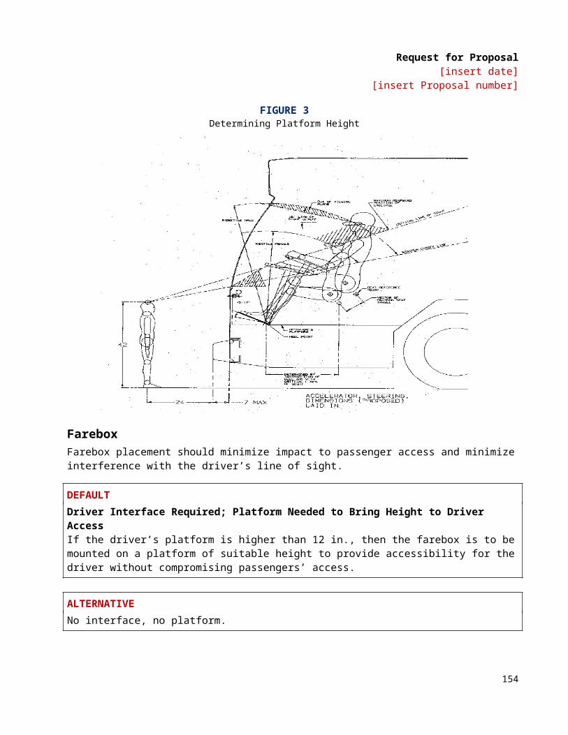
Request for Proposal[insert date]
[insert Proposal number]
ALTERNATIVEManually Adjustable Temperature Control Set PointThe climate control system shall have the provision to allow the driver to adjust the temperature control set-point at a minimum of between 68 and 72 °F. From then on, all interior climate control system requirements shall be attained automatically, unless re-adjusted by driver.
The driver shall have full control over the defroster and driver’s heater. The driver shall be able to adjust the temperature in the driver’s area through air distribution and fans. The interior climate control system shall switch automatically to the ventilating mode if the refrigerant compressor or condenser fan fails.
Interior temperature distribution shall be uniform to the extent practicable to prevent hot and/or cold spots. After stabilization with doors closed, the temperatures between any two points in the passenger compartment in the same vertical plane, and 6 to 72 in. above the floor, shall not vary by more than 5 °F with doors closed. The interior temperatures, measured at the same height above the floor, shall not vary more than ± 5 °F from the front to the rear from the average temperature determined in accordance with APTA’s “Recommended Instrumentation and Performance Testing for Transit Bus Air Conditioning System.” Variations of greater than ± 5 °F will be allowed for limited, localized areas provided the majority of the measured temperatures fall within the specified requirement.
TS 54. Air Flow TS 54.1 Passenger AreaThe cooling mode of the interior climate control system shall introduce air into the bus at or near the ceiling height at a minimum rate of 25 cubic ft per minute (cfm) per passenger based on the standard configuration bus carrying a number of passengers equal to 150 percent of the seated load. Airflow shall be evenly distributed throughout the bus, with air velocity not exceeding 100 ft per minute on any passenger. The ventilating mode shall provide air at a minimum flow rate of 20 cfm per passenger.
Airflow may be reduced to 15 cfm per passenger (150 percent of seated load) when operating in the heating mode. The fans shall not activate until the heating element has warmed sufficiently to ensure at least 70 °F air outlet temperature. The heating air outlet temperature shall not exceed 120 °F under any normal operating conditions.
The climate control blower motors and fan shall be designed such that their operation complies with the interior noise level requirements.
DEFAULTNo “Fresh Air” Requirements[To be used by agencies that have an operating profile where the door opening cycle results in effectively providing an adequate “fresh air” mixture.]
ALTERNATIVERequirement for 10 percent “Fresh Air” MixtureThe air shall be composed of no less than 10 percent outside air.
156
Request for Proposal[insert date]
[insert Proposal number]
ALTERNATIVEAir purification system.
ALTERNATIVE Ionization system.
ALTERNATIVE Ultraviolet system.
TS 54.2 Driver’s AreaThe bus interior climate control system shall deliver at least 100 cfm of air to the driver’s area when operating in the ventilating and cooling modes. Adjustable nozzles shall permit variable distribution or shutdown of the airflow. Airflow in the heating mode shall be reduced proportionally to the reduction of airflow into the passenger area. The windshield defroster unit shall meet the requirements of SAE Recommended Practice J382, “Windshield Defrosting Systems Performance Requirements,” and shall have the capability of diverting heated air to the driver’s feet and legs. The defroster or interior climate control system shall maintain visibility through the driver’s side window.
TS 54.3 Controls for the Climate Control System (CCS)The controls for the driver’s compartment for heating, ventilation and cooling systems shall be integrated and shall meet the following requirements:
• The heat/defrost system fan shall be controlled by a separate switch that has an “off” position and at least two positions for speed control. All switches and controls shall preclude the possibility of clothing becoming entangled, and shields shall be provided, if required. If the fans are approved by the Agency, an “on-off” switch shall be located to the right of or near the main defroster switch.
• A manually operated control valve shall control the coolant flow through the heater core.• If a cable-operated manual control valve is used, the cable length shall be kept to a minimum to
reduce cable seizing. Heater water control valves shall be “positive” type, closed or open. The method of operating remote valves shall require the concurrence of the Agency project manager.
TS 54.4 Driver’s Compartment RequirementsA separate heating, ventilation and defroster system for the driver’s area shall be provided and shall be controlled by the driver. The system shall meet the following requirements:
• The heater and defroster system shall provide heating for the driver and heated air to completely defrost and defog the windshield, driver’s side window, and the front door glasses in all operating conditions. Fan(s) shall be able to draw air from the bus body interior and/or the exterior through a control device and pass it through the heater core to the defroster system and over the driver’s feet. A minimum capacity of 100 cfm shall be provided. The driver shall have complete control of the heat and fresh airflow for the driver’s area.
• The defroster supply outlets shall be located at the lower edge of the windshield. These outlets shall be durable and shall be free of sharp edges that can catch clothes during normal daily cleaning. The system shall be such that foreign objects such as coins or tickets cannot fall into the defroster air
157
Request for Proposal[insert date]
[insert Proposal number]
outlets. Adjustable ball vents or louvers shall be provided at the left of the driver’s position to allow direction of air onto the side windows.
A ventilation system shall be provided to ensure driver comfort and shall be capable of providing fresh air in both the foot and head areas. Vents shall be controllable by the driver from the normal driving position. Decals shall be provided, indicating “operating instructions” and “open” and “closed” positions. When closed, vents shall be sealed to prevent the migration of water or air into the bus.
TS 54.5 Driver’s CoolingDEFAULTNo dedicated evaporator.
ALTERNATIVESeparate Dedicated EvaporatorUsing a separate, dedicated evaporator, the Climate Control System shall be designed to maintain the driver’s compartment temperatures within the range specified for the passenger compartment. The unit shall operate when the climate control switch is in the “Cool” position. It shall have a separate thermostatic control.
ALTERNATIVEA separate fan unit shall provide 100 cfm of air to the driver’s area through directionally adjustable nozzles and an infinitely variable fan control, both of which shall be located above and ahead of the driver.
ALTERNATIVEAir from the evaporator shall be provided to the driver’s area through vents located on the dash in front of the driver.
ALTERNATIVEDriver’s booster blower.
TS 55. Air Filtration Air shall be filtered before discharge into the passenger compartment. The filter shall meet the ANSI/ASHRAE 52.1 requirement for 5 percent or better atmospheric dust spot efficiency, 50 percent weight arrestance, and a minimum dust holding capacity of 120 g per 1000 cfm cell. Air filters shall be easily removable for service.
DEFAULTCleanable FiltersAir filters shall be cleanable.
ALTERNATIVEDisposable Type FiltersAir filters shall be of disposable type.
158

Request for Proposal[insert date]
[insert Proposal number]
ALTERNATIVEOther Type FiltersAir filters shall be [Agency to specify].
TS 56. Roof Ventilators DEFAULTOne Roof Ventilator One ventilator shall be provided in the roof of the bus.
ALTERNATIVETwo Roof Ventilators Two roof ventilators shall be provided in the roof of the bus, one approximately over or just forward of the front axle and the other approximately over the rear axle.
Each ventilator shall be easily opened and closed manually. When open with the bus in motion, this ventilator shall provide fresh air inside the bus. The ventilator shall cover an opening area no less than 425 sq in. and shall be capable of being positioned as a scoop with either the leading or trailing edge open no less than 4 in., or with all four edges raised simultaneously to a height of no less than 3½ in. An escape hatch shall be incorporated into the roof ventilator. Roof ventilator(s) shall be sealed to prevent entry of water when closed.
ALTERNATIVE (ARTICULATED BUSES)Three roof ventilators.
ALTERNATIVEAn electronically controlled hatch shall be installed.
ALTERNATIVEA tool shall be provided to manually open and close hatch.
TS 57. Maintainability Manually controlled shut-off valves in the refrigerant lines shall allow isolation of the compressor and dehydrator filter for service. To the extent practicable, self-sealing couplings utilizing O-ring seals shall be used to break and seal the refrigerant lines during removal of major components, such as the refrigerant compressor. Shut-off valves may be provided in lieu of self-sealing couplings. The condenser shall be located to efficiently transfer heat to the atmosphere and shall not ingest air warmed above the ambient temperature by the bus mechanical equipment, or to discharge air into any other system of the bus. The location of the condenser shall preclude its obstruction by wheel splash, road dirt or debris. HVAC components located within 6 in. of floor level shall be constructed to resist damage and corrosion.
ALTERNATIVEHigh and low refrigerant pressure analog gauges to be located in the return air area.
159
Request for Proposal[insert date]
[insert Proposal number]
ALTERNATIVEHigh and low refrigerant pressure electronic gauges to be located in the return air area.
NOTE: The Agency may include the following sections if an alternative for colder ambient performance is specified above.
TS 58. Entrance/exit area heatingDEFAULTNo requirements for entrance/exit area heating.
ALTERNATIVEEntrance/Exit Area HeatingHeat shall be supplied to the entrance and exit areas to maintain a tread surface temperature no less than 35 °F in an ambient of -10 °F to prevent accumulation of snow, ice or slush with the bus operating under design operating profile and corresponding door opening cycle.
TS 59. Floor-Level HeatingDEFAULTNo requirements for floor-level heating.
ALTERNATIVEForced-Air Floor-Level HeatingSufficient floor-level heaters shall be provided to evenly supply heated forced air through floor ducts across the length of bus. Floor ducts may be discontinued at the upper level, but additional provisions to prevent cold floors and ensure temperature uniformity shall be included. Control of the floor-level heating shall be through the main heating system electronic control.
ALTERNATIVEConvector Air Floor-Level HeatingSufficient floor-level heaters shall be provided that evenly supply convector air across the length of the bus. Control of the floor-level heating shall be through the main heating system’s electronic control.
ALTERNATIVEWarm Wall HeatingSufficient heaters shall be provided with ducting to blow warm air upward through a cavity in the wall and discharge the warm air at the base of the windows. Control of the warm wall heating shall be through the main heating system electronic control.
160
Request for Proposal[insert date]
[insert Proposal number]
EXTERIOR PANELS, FINISHES AND EXTERIOR LIGHTINGTS 60. Design The bus shall have a clean, smooth, simple design, primarily derived from bus performance requirements and passenger service criteria. The exterior and body features, including grilles and louvers, shall be shaped to facilitate cleaning by automatic bus washers without snagging washer brushes. Water and dirt shall not be retained in or on any body feature to freeze or bleed out onto the bus after leaving the washer. The body and windows shall be sealed to prevent leaking of air, dust or water under normal operating conditions and during cleaning in automatic bus washers for the service life of the bus.
Exterior panels shall be sufficiently stiff to minimize vibration, drumming or flexing while the bus is in service. When panels are lapped, the upper and forward panels shall act as a watershed. However, if entry of moisture into the interior of the vehicle is prevented by other means, then rear cap panels may be lapped otherwise. The windows, hatches and doors shall be able to be sealed. Accumulation of spray and splash generated by the bus’s wheels shall be minimized on windows and mirrors.
TS 60.1 MaterialsBody materials shall be selected and the body fabricated to reduce maintenance, extend durability and provide consistency of appearance throughout the service life of the bus. Detailing shall be kept simple, and add-on devices and trim shall be minimized and integrated into the basic design.
DEFAULTNo requirement for protection against graffiti/vandalism for body material surfaces.
ALTERNATIVERequirements for protection against graffiti/vandalism for body material surfaces.
TS 60.2 Roof-Mounted EquipmentA non-skid, clearly marked walkway or steps shall be incorporated on the roof to provide access to equipment without damaging any system or bus paneling.
TS 61. Pedestrian SafetyExterior protrusions along the side and front of the bus greater than ½ in. and within 80 in. of the ground shall have a radius no less than the amount of the protrusion. The exterior rearview mirrors, cameras and required lights and reflectors are exempt from the protrusion requirement. Advertising frames shall protrude no more than ⅞ in. from the body surface. Grilles, doors, bumpers and other features on the sides and rear of the bus shall be designed to minimize toeholds or handholds.
Exterior protrusions shall not cause a line-of-sight blockage for the driver.
TS 62. Repair and ReplacementTS 62.1 Side Body PanelsStructural elements supporting exterior body panels shall allow side body panels below the windows to be repaired in lengths not greater than 12.5 ft.
161

Request for Proposal[insert date]
[insert Proposal number]
DEFAULTStandard attachment of side body panels.
ALTERNATIVEEasily Replaceable Lower Side Body PanelsThe lower section (approximately 17.5 in.) of the side body panels (low-floor buses) or skirt panels (high-floor buses) shall be made of impact-resistant material and shall be easily and quickly replaceable.
ALTERNATIVEEasily Replaceable Full-Height Side Body Panels Easily replaceable full-height side body panels between the window and floor shall be easily and quickly replaceable in sections.
TS 63. Rain GuttersRain gutters shall be provided to prevent water flowing from the roof onto the passenger doors and driver’s side window. When the bus is decelerated, the gutters shall not drain onto the windshield, driver’s side window or door boarding area. Cross-sections of the gutters shall be adequate for proper operation.
TS 64. License Plate ProvisionsProvisions shall be made to mount standard-size U.S./Canada license plates per SAE J686 on the front and rear of the bus. These provisions shall direct-mount or recess the license plates so that they can be cleaned by automatic bus-washing equipment without being caught by the brushes. The rear license plate provision shall be illuminated per SAE J587.
ALTERNATIVENo plate or holder provision is required.
ALTERNATIVENo Front Plate or Holder is RequiredLocation to be provided to OEM.
TS 64.1 Rub railsDEFAULTNo requirement for rub rails.
ALTERNATIVERequirement for Rub RailsRub rails composed of flexible, resilient material shall be provided to protect both sides of the bus body from damage caused by minor sideswipe accidents with automobiles. Rub rails shall have vertical dimensions of no less than 2 in. (50 mm) with the centerline no higher than 35 in. above the ground between the wheel wells. The rub rails shall withstand impacts of 200 ft-lbs of energy from a steel-faced spherical missile no less than
162
Request for Proposal[insert date]
[insert Proposal number]
9 in. in diameter and of a 500 lb load applied anywhere along their length by a rigid plate 1 ft in length, wider than the rub rail, and with a ¼ in. end radii, with no visible damage to the rub rail, retainer or supporting structure.
The rub rail may be discontinued at doorways and wheel wells. A damaged portion of the rub rail shall be replaceable without requiring removal or replacement of the entire rub rail.
NOTE: Installation of rub rails may preclude the installation and or size of exterior advertising signs or racks.
TS 65. Fender Skirts Features to minimize water spray from the bus in wet conditions shall be included in wheel housing design. Any fender skirts shall be easily replaceable. They shall be flexible if they extend beyond the allowable body width. Wheels and tires shall be removable with the fender skirts in place.
ALTERNATIVENo fender skirts required.
TS 66. Wheel coversDEFAULTWheel covers not required.
ALTERNATIVEWheel covers required (BRT buses).
TS 66.1 Splash Aprons DEFAULTStandard Splash ApronsSplash aprons, composed of ¼ in. minimum composition or rubberized fabric, shall be installed behind and/or in front of wheels as needed to reduce road splash and protect underfloor components. The splash aprons shall extend downward to within 6 in. off the road surface at static conditions. Apron widths shall be no less than tire widths. Splash aprons shall be bolted to the bus understructure. Splash aprons and their attachments shall be inherently weaker than the structure to which they are attached. The flexible portions of the splash aprons shall not be included in the road clearance measurements. Splash apron shall be installed as necessary to protect the wheelchair loading device from road splash. Other splash aprons shall be installed where necessary to protect bus equipment.
ALTERNATIVEFull width rear splash apron.
ALTERNATIVEOther Locations RequiredSplash apron in front of either or both front wheels to reduce splashing on ramp/lift and left mirror.
163
Request for Proposal[insert date]
[insert Proposal number]
TS 67. Service Compartments and Access Doors TS 67.1 Access DoorsConventional or pantograph hinged doors shall be used for the engine compartment and for all auxiliary equipment compartments including doors for checking the quantity and adding to the engine coolant, engine lubricant and transmission fluid. Access openings shall be sized for easy performance of tasks within the compartment, including tool operating space. Access doors shall be of rugged construction and shall maintain mechanical integrity and function under normal operations throughout the service life of the bus. They shall close flush with the body surface. All doors shall be hinged at the top or on the forward edge and shall be prevented from coming loose or opening during transit service or in bus washing operations. All access doors shall be retained in the open position by props or counterbalancing with over-center or gas-filled springs with safety props and shall be easily operable by one person. Springs and hinges shall be corrosion resistant. Latch handles shall be flush with, or recessed behind, the body contour and shall be sized to provide an adequate grip for opening. Access doors, when opened, shall not restrict access for servicing other components or systems.
If precluded by design, the manufacturer shall provide door design information specifying how the requirements are met.
TS 67.2 Access Door Latch/Locks DEFAULTRequirement for Latches on Access DoorsAccess doors larger than 100 sq in. in area shall be equipped with corrosion-resistant flush-mounted latches or locks except for coolant and fuel fill access doors. All such access doors that require a tool to open shall be standardized throughout the vehicle and will require a nominal 5/16 in. square male tool to open or lock.
ALTERNATIVEOther Locks and Latches[Agency may define any required locks or latches for access doors.]
TS 68. BumpersTS 68.1 LocationBumpers shall provide impact protection for the front and rear of the bus with the top of the bumper being 27 in., ± 2 in., above the ground. Bumper height shall be such that when one bus is parked behind another, a portion of the bumper faces will contact each other.
TS 68.2 Front BumperNo part of the bus, including the bumper, shall be damaged as a result of a 5 mph impact of the bus at curb weight with a fixed, flat barrier perpendicular to the bus’s longitudinal centerline. The bumper shall return to its pre-impact shape within 10 minutes of the impact. The bumper shall protect the bus from damage as a result of 6.5 mph impacts at any point by the common carriage with contoured impact surface defined in Figure 2 of FMVSS 301 loaded to 4000 lbs parallel to the longitudinal centerline of the bus. It shall protect the bus from damage as a result of 5.5 mph impacts into the corners at a 30-degree angle to the longitudinal centerline of the bus. The energy absorption system of the bumper shall be independent of every power system of the bus and shall not require service or maintenance in normal operation during the service life of the bus. The bumper may increase the overall bus length specified by no more than 7 in.
164

Request for Proposal[insert date]
[insert Proposal number]
ALTERNATIVEMounting provisions for integrated bike rack.
DEFAULTStandard bumper.
ALTERNATIVEIntegrated Design with Recessed Middle PortionBumper shall be an integrated design with the coach styling and be recessed in the middle portion to provide for mounting of a bike rack if necessary.
TS 68.3 Rear BumperNo part of the bus, including the bumper, shall be damaged as a result of a 2 mph impact with a fixed, flat barrier perpendicular to the longitudinal centerline of the bus. The bumper shall return to its pre-impact shape within 10 minutes of the impact. When using a yard tug with a smooth, flat plate bumper 2 ft wide contacting the horizontal centerline of the rear bumper, the bumper shall provide protection at speeds up to 5 mph, over pavement discontinuities up to 1 in. high, and at accelerations up to 2 mph/sec. The rear bumper shall protect the bus, when impacted anywhere along its width by the common carriage with contoured impact surface defined in Figure 2 of FMVSS 301 loaded to 4000 lbs, at 4 mph parallel to or up to a 30-degree angle to, the longitudinal centerline of the bus. The rear bumper shall be shaped to preclude unauthorized riders standing on the bumper. The bumper shall not require service or maintenance in normal operation during the service life of the bus. The bumper may increase the overall bus length specified by no more than 7 in.
TS 68.4 Bumper MaterialBumper material shall be corrosion-resistant and withstand repeated impacts of the specified loads without sustaining damage. Visible surfaces shall be black. These bumper qualities shall be sustained throughout the service life of the bus.
TS 69. Finish and ColorTS 69.1 AppearanceAll exterior surfaces shall be smooth and free of wrinkles and dents. Exterior surfaces to be painted shall be properly prepared as required by the paint system Supplier prior to application of paint to assure a proper bond between the basic surface and successive coats of original paint for the service life of the bus. Drilled holes and cutouts in exterior surfaces shall be made prior to cleaning, priming and painting, where possible, to prevent corrosion. The bus shall be completely painted prior to installation of exterior lights, windows, mirrors and other items that are applied to the exterior of the bus. Body filler materials may be used for surface dressing, but not for repair of damaged or improperly fitted panels.
Paint shall be applied smoothly and evenly with the finished surface free of visible dirt and the following other imperfections:
• blisters or bubbles appearing in the topcoat film• chips, scratches, or gouges of the surface finish• cracks in the paint film• craters where paint failed to cover due to surface contamination
165

Request for Proposal[insert date]
[insert Proposal number]
• overspray• peeling• runs or sags from excessive flow and failure to adhere uniformly to the surface• chemical stains and water spots• dry patch due to incorrect mixing of paint activators• buffing swirls
All exterior finished surfaces shall be impervious to diesel fuel, gasoline and commercial cleaning agents. Finished surfaces shall resist damage by controlled applications of commonly used graffiti-removing chemicals.
Proper adhesion between the basic surface and successive coats of the original paint shall be measured using an Elcometer adhesion tester as outlined in ASTM D4541-85. Adhesion shall be a minimum 300 ft-lbs. The bus manufacturer shall supply test samples of the exterior surface for each step of the painting process that may be subject to adhesion testing per ASTM G4541-87 and ASTM D4145-85. ASTM D4541-93 may be used for inspection testing during assembly of the vehicle.
DEFAULTStandard Contractor exterior paint finish quality.
ALTERNATIVEHigh Gloss External Paint Finish QualityPainted surfaces shall have a minimum 95 gloss and an orange peel rating of 7 or more on the Advanced Coating Technologies, Inc., orange peel standard panels set #APR 14941 or Agency accepted wave scan equipment. Paint shall last a minimum of six years with a minimum gloss of 90 as measured in ASTM E97-92, “Standard Test Method For Directional Reflectance.”
DEFAULTStandard OEM exterior paint system.
ALTERNATIVEBasecoat/ClearCoat paint system.
ALTERNATIVEMaintenance-Free Exterior Finish, Color Impregnated Panels or Unpainted PanelsExcept for periodic cleaning, exterior surfaces of the bus shall be maintenance-free, permanently colored and not require refinish/repaint for the life of the vehicle. In general, the exterior surfaces shall be white. Durable, peel-resistant, pressure-sensitive appliqués shall be used for any striping and coloring required.
NOTE: Agency should insert approved paints, color scheme and graphics
TS 70. Decals, Numbering and Signing Monograms, numbers and other special signing shall be applied to the inside and outside of the bus as required. Signs shall be durable and fade-, chip- and peel-resistant. They may be painted signs, decals or
166
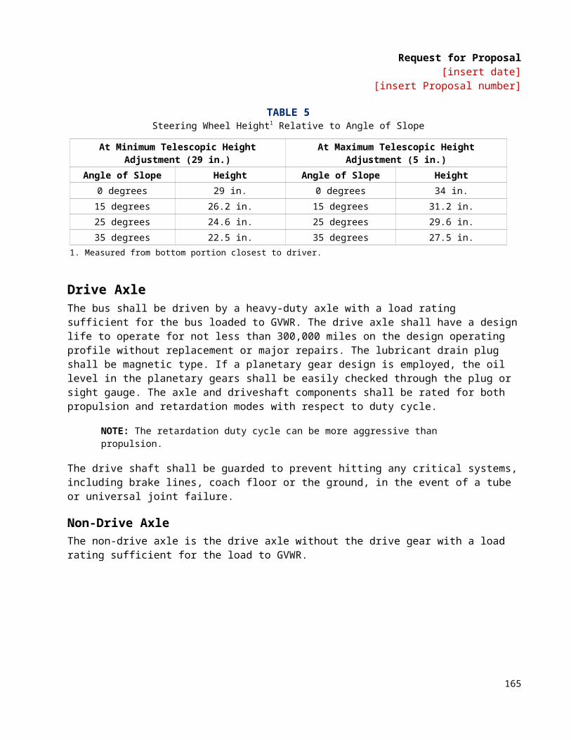
Request for Proposal[insert date]
[insert Proposal number]
pressure-sensitive appliqués. All decals shall be installed per the decal Supplier recommendations. Signs shall be provided in compliance with the ADA requirements defined in 49 CFR Part, Subpart B, 38.27.
NOTE: Agency should supply a list of interior and exterior decals including size and location
TS 70.1 Passenger InformationADA priority seating signs as required and defined by 49 CFR, Part 38.27 shall be provided to identify the seats designated for passengers with disabilities.
Requirements for a public information system in accordance with 49 CFR, Part 38.35 shall be provided.
TS 71. Exterior Lighting Exterior lighting and reflectors shall comply, as applicable, with Part 393, Subpart B of the FMCSA and FMVSS 108.
All exterior lights shall be designed to prevent entry and accumulation of moisture or dust. Commercially available LED-type lamps shall be utilized at all exterior lamp locations except headlights. Lamps, lenses and fixtures shall be interchangeable to the extent practicable. Two hazard lamps at the rear of the bus shall be visible from behind when the engine service doors are opened. Light lenses shall be designed and located to prevent damage when running the vehicle through an automatic bus washer. Front marker (clearance) lights along with lights located on the roof and sides of the bus shall have protective shields or be of the flush mount type to protect the lens against minor impacts.
DEFAULTStandard LampsAll LED lamps shall be standard installation of the OEM. The entire assembly shall be specifically coated to protect the light from chemical and abrasion degradation.
ALTERNATIVEPotted LampsLED lamps shall be potted type and designed to last the life of the bus.
DEFAULTStandard SizeSize of LED lamps used for tail, brake and turn signal lamps shall be standard installation of OEM.
ALTERNATIVELarger SizeLED lamps used for tail, brake and turn signal lamps shall be a minimum of 7 in. in diameter.
TS 71.1 Backup Light/AlarmVisible and audible warnings shall inform following vehicles or pedestrians of reverse operation. Visible reverse operation warning shall conform to SAE Standard J593. Audible reverse operation warning shall conform to SAE Recommended Practice J994 Type C or D.
167

Request for Proposal[insert date]
[insert Proposal number]
TS 71.2 Doorway LightingLamps at the front and rear passenger doorways shall comply with ADA requirements and shall activate only when the doors open. These lamps shall illuminate the street surface to a level of no less than 1 foot-candle for a distance of 3 ft outward from the outboard edge of the door threshold. The lights may be positioned above or below the lower daylight opening of the windows and shall be shielded to protect passengers’ eyes from glare.
TS 71.3 Turn SignalsDEFAULTStandard Turn SignalsTurn-signal lights shall be provided on the front, rear, curb and street sides of the bus in accordance with FMVSS 108 and Part 393, Subpart B of the FMCSA as applicable.
ALTERNATIVEWraparound Front Turn SignalsFront turn signals shall be of wrap-around design or shall be designed to be visible from the front and the near side of the bus.
TS 71.4 HeadlightsRoved headlamps shall be designed for replacement without removing the headlamp bezel.
DEFAULTStandard InstallationStandard OEM headlight installation shall be provided in accordance with FMVSS 108 and Part 393, Subpart B of the FMCSA as applicable.
ALTERNATIVEDaytime Running LightsHeadlamps shall incorporate a daytime running light feature.
ALTERNATIVELED/HalogenHeadlamps shall be LED/halogen, sealed beam.
ALTERNATIVESpecify Design Life[Headlamps design life to be specified in units of hours by the Agency.]
TS 71.5 Brake LightsBrake lights shall be provided in accordance with FMVSS 108 and Part 393, Subpart B of the FMCSA as applicable.
168
Request for Proposal[insert date]
[insert Proposal number]
DEFAULTNo High/Center Mount Brake Lamp or Deceleration Warning LampsBus shall not include a high/center mount brake lamp and/or deceleration warning indicator lamps.
ALTERNATIVEHigh and Center Mount Red Brake LampBus shall include red, high and center mount brake lamp(s) along the backside of the bus in addition to the lower brake lamps required under FMVSS 108. The high and center mount brake lamp(s) shall illuminate steady with brake application. [Agency to specify the size of the high and center mount brake lamp(s).]
ALTERNATIVEHigh and Center Mount Amber LampBus shall include amber high and center mount lamp(s) along the backside of the bus that illuminate steady when the transmission is in forward mode and when the throttle is completely released (0 percent engagement). The amber lamps shall automatically extinguish, regardless of transmission and throttle condition, with brake application. Operation of the amber lamps shall be programmable with the multiplex system. [Agency to specify the size of the high and center mount, amber lamp(s).]
TS 71.6 Service Area Lighting (Interior and Exterior)LED lamps shall be provided in the engine and all other compartments where service may be required to generally illuminate the area for night emergency repairs or adjustments. These service areas shall include, but not be limited to, the engine compartment, the communication box, junction/apparatus panels and passenger door operator compartments. Lighting shall be adequate to light the space of the service areas to levels needed to complete typical emergency repairs and adjustments. The service area lamps shall be suitable for the environment in which they are mounted.
Engine compartment lamps shall be controlled by a switch mounted near the rear start controls. All other service area lamps shall be controlled by switches mounted on or convenient to the lamp assemblies. Power to the service area lighting shall be programmable. Power shall latch on with activation of the switch and shall be automatically discontinued (timed out) after 30 minutes to prevent damage caused by inadvertently leaving the service area lighting switch in the on position after repairs are made.
INTERIOR PANELS AND FINISHESTS 72. General RequirementsMaterials shall be selected on the basis of maintenance, durability, appearance, safety, flammability and tactile qualities. Materials shall be strong enough to resist everyday abuse and be vandalism and corrosion resistant. Trim and attachment details shall be kept simple and unobtrusive. Interior trim shall be secured to avoid resonant vibrations under normal operational conditions.
Interior surfaces more than 10 in. below the lower edge of the side windows or windshield shall be shaped so that objects placed on them fall to the floor when the coach is parked on a level surface. Any components and other electrical components within close proximity to these surfaces shall also be resistant to this cleaning method.
169
Request for Proposal[insert date]
[insert Proposal number]
DEFAULTNo requirement for anti-graffiti/vandalism surface treatments.
ALTERNATIVERequirements for additional anti-graffiti/vandalism treatments for interior surfaces.
ALTERNATIVEInternal surfaces, as possible, to be stainless steel or other resistant material.
TS 73. Interior Panels Panels shall be easily replaceable and tamper-resistant. They shall be reinforced, as necessary, to resist vandalism and other rigors of transit bus service. Individual trim panels and parts shall be interchangeable to the extent practicable.
DEFAULTInterior panel required to meet FMVSS 302.
ALTERNATIVEFire ResistanceMaterials shall comply with the Recommended Fire Safety Practices defined in FTA Docket 90-A, dated October 20, 1993.
ALTERNATIVETextured stainless steel.
ALTERNATIVEAnodized or powder-coated aluminum.
ALTERNATIVEComposite.
ALTERNATIVEScratch-resistant plastic.
ALTERNATIVEMelamine-type material.
170
Request for Proposal[insert date]
[insert Proposal number]
ALTERNATIVECarpeting.
TS 73.1 Driver Area BarrierA barrier or bulkhead between the driver and the street-side front passenger seat shall be provided. The barrier shall minimize glare and reflections in the windshield directly in front of the barrier from interior lighting during night operation. Location and shape must permit full seat travel and reclining possibilities that can accommodate the shoulders of a 95th-percentile male. The partition shall have a side return and stanchion to prevent passenger from reaching the driver by standing behind the driver’s seat. The lower area between the seat and panel must be accessible to the driver. The partition must be strong enough in conjunction with entire partition assembly for mounting of such equipment as flare kits, fire extinguishers (1.2 kg), microcomputer, public address amplifier, etc. Dark or black panels are preferred behind the driver’s head. The panel should be isolated for noise control and attached with rubber grommets.
DEFAULTWheel-Well-to-Ceiling Configuration of Driver’s BarrierThe driver’s barrier shall extend from the top of the wheel well to the ceiling the level of the seated driver and shall fit close to the bus side windows and wall to prevent passengers from reaching the driver or the driver’s personal effects.
ALTERNATIVEFull-Height (Floor-to-Ceiling) Configuration of Driver’s BarrierThe driver’s barrier shall extend continually from the floor area to the ceiling and from the bus wall to the first stanchion immediately behind the driver to provide security to the driver and limit passenger conversation.
ALTERNATIVEDriver enclosure or door.
TS 73.2 Modesty PanelsSturdy divider panels constructed of durable, unpainted, corrosion-resistant material complementing the interior shall be provided to act as both a physical and visual barrier for seated passengers.
Design and installation of modesty panels located in front of forward-facing seats shall include a handhold or grab handle along its top edge. These dividers shall be mounted on the sidewall and shall project toward the aisle no farther than passenger knee projection in longitudinal seats or the aisle side of the transverse seats. Modesty panels shall extend from at least the window opening of the side windows, and those forward of transverse seats shall extend downward to 1 and 1½ in. above the floor. Panels forward of longitudinal seats shall extend to below the level of the seat cushion. Dividers positioned at the doorways shall provide no less than a 2½ in. clearance between the modesty panel and a fully open, inward opening door, or the path of a deploying flip-out ramp to protect passengers from being pinched. Modesty panels installed at doorways shall be equipped with grab rails if passengers assist are not provided by other means.
171
Request for Proposal[insert date]
[insert Proposal number]
The modesty panel and its mounting shall withstand a static force of 250 lbs applied to a 4 × 4 in. area in the center of the panel without permanent visible deformation.
ALTERNATIVEAdditional floor clearances for cleaning, toe clearance.
ALTERNATIVEClear non-glass panel from above the modesty panel to the top of the daylight opening and attached to the stanchion.
TS 73.3 Front EndThe entire front end of the bus shall be sealed to prevent debris accumulation behind the dash and to prevent the driver’s feet from kicking or fouling wiring and other equipment. The front end shall be free of protrusions that are hazardous to passengers standing at the front of the standee line area of the bus during rapid decelerations. Paneling across the front of the bus and any trim around the driver’s compartment shall be formed metal or composite material. Composite dash panels shall be reinforced as necessary, vandal-resistant and replaceable. All colored, painted and plated parts forward of the driver’s barrier shall be finished with a surface that reduces glare. Any mounted equipment must have provision to support the weight of equipment.
TS 73.4 Rear BulkheadThe rear bulkhead and rear interior surfaces shall be material suitable for exterior skin; painted and finished to exterior quality; or paneled with melamine-type material, composite, scratch-resistant plastic or carpeting and trimmed with stainless steel, aluminum or composite.
The rear bulkhead paneling shall be contoured to fit the ceiling, side walls and seat backs so that any litter or trash will tend to fall to the floor or seating surface when the bus is on a level surface. Any air vents in this area shall be louvered to reduce airflow noise and to reduce the probability of trash or liter being thrown or drawn through the grille. If it is necessary to remove the panel to service components located on the rear bulkhead, the panel shall be hinged or shall be able to be easily removed and replaced. Grilles where access to or adjustment of equipment is required shall be heavy-duty and designed to minimize damage and limit unauthorized access.
TS 73.5 HeadliningCeiling panels shall be made of durable, corrosion resistant, easily cleanable material. Headlining shall be supported to prevent buckling, drumming or flexing and shall be secured without loose edges. Headlining materials shall be treated or insulated to prevent marks due to condensation where panels are in contact with metal members. Moldings and trim strips, as required to make the edges tamperproof, shall be stainless steel, aluminum or plastic, colored to complement the ceiling material. Headlining panels covering operational equipment that is mounted above the ceiling shall be on hinges for ease of service but retained to prevent inadvertent opening.
TS 73.6 FasteningInterior panels shall be attached so that there are no exposed unfinished or rough edges or rough surfaces. Fasteners should be corrosion resistant. Panels and fasteners shall not be easily removable by passengers. Exposed interior fasteners should be minimized, and where required shall be tamper-resistant.
172
Request for Proposal[insert date]
[insert Proposal number]
TS 73.7 InsulationAny insulation material used between the inner and outer panels shall minimize the entry and/or retention of moisture. Insulation properties shall be unimpaired during the service life of the bus. Any insulation material used inside the engine compartment shall not absorb or retain oils or water and shall be designed to prevent casual damage that may occur during maintenance operations.
The combination of inner and outer panels on the sides, roof, wheel wells and ends of the bus, and any material used between these panels, shall provide a thermal insulation sufficient to meet the interior temperature requirements. The bus body shall be thoroughly sealed so that the driver or passengers cannot feel drafts during normal operations with the passenger doors closed.
DEFAULTFMVSS 302Insulation shall meet the requirements of FMVSS 302.
ALTERNATIVEFTA Docket 90-AAll insulation materials shall comply with the Recommended Fire Safety Practices defined in FTA Docket 90-A, dated October 20, 1993.
TS 73.8 Floor Covering The floor covering shall have a non-skid walking surface that remains effective in all weather conditions. The floor covering, as well as transitions of flooring material to the main floor and to the entrance and exit area, shall be smooth and present no tripping hazards. Seams shall be sealed/welded per manufacturer’s specifications. The standee line shall be approximately 2 in. wide and shall extend across the bus aisle. The color and pattern shall be consistent throughout the floor covering.
ALTERNATIVEAdditional RequirementsAny areas on the floor that are not intended for standees, such as areas “swept” during passenger door operation, shall be clearly and permanently marked.
The floor shall be easily cleaned and shall be arranged to minimize debris accumulation.
A one-piece center strip shall extend from the vertical wall of the rear settee between the aisle sides of transverse seats to the standee line. If the floor is of a bi-level construction, then the center strip shall be one piece at each level. The covering between the center strip and the wheel housings may be separate pieces. At the rear door, however, a separate strip as wide as the door shall extend from the center strip to the outboard edge of the rear/exit area.
The floor under the seats shall be covered with smooth surface flooring material. The floor covering shall closely fit the sidewall in a fully sealed butt joint or extend to the top of the cove.
173
Request for Proposal[insert date]
[insert Proposal number]
TS 73.9 Interior Lighting The light source shall be located to minimize windshield glare, with distribution of the light focused primarily on the passengers’ reading plane while casting sufficient light onto the advertising display. The lighting system may be designed to form part of or the entire air distribution duct.
The lens material shall be translucent polycarbonate. Lenses shall be designed to effectively “mask” the light source. Lenses shall be sealed to inhibit incursion of dust and insects yet be easily removable for service. Access panels shall be provided to allow servicing of components located behind light panels. If necessary, the entire light fixture shall be hinged.
TS 73.10 PassengerDEFAULTAutomatically Dimming First Row LightsThe first light on each side (behind the driver and the front door) is normally turned on only when the front door is opened, in “night run” and “night park.” As soon as the door closes, these lights shall go out. These lights shall be turned on at any time if the toggle switch is in the “on” position.
ALTERNATIVEDimming Second Row LightsTo help eliminate windshield reflection on suburban roads where street lighting is at a low level, the second light on each side, when “night run” or “night park” is selected, shall be controlled by the toggle switch; off in “off” and on in “normal.” These lights shall be turned on at any time if the toggle switch is in the “on” position.
All interior lighting shall be turned off whenever the transmission selector is in reverse and the engine run switch is in the “on” position.
The interior lighting design shall require the approval of the Agency.
DEFAULTLED lights.
ALTERNATIVEFluorescent LightsFluorescent tubes shall be a maximum 6 ft in length, single-pin, T-12 type (with exceptions granted for extinguishing or dimming fixtures, as noted below).
Individual ballast units shall be provided for each light fixture. Ballast shall have a fire-resistant housing, minimum operating frequency of above audible range, reverse polarity protection and integrated circuit breaker/automatic thermal protection.
ALTERNATIVEEnhanced design ballast that minimize arcing and carries a type and CC UL935 certification.
174
Request for Proposal[insert date]
[insert Proposal number]
DEFAULTFirst Light Modules Dim/Extinguish When Front Door is ClosedWhen the master switch is in the “run” or “night/run” mode, the first light module on each side of the coach shall automatically extinguish or dim when the front door is in the closed position and illuminate when the door is opened. This shall be accomplished through the use of a ballast specifically designed for this type application without diminishing the life of the fluorescent tubes.
ALTERNATIVENo Dimming/Extinguishing of First Light Modules When Front Door is ClosedNo dimming/extinguishing feature of first light modules shall be provided.
TS 73.11 Driver AreaThe driver’s area shall have a light to provide general illumination, and it shall illuminate the half of the steering wheel nearest the driver to a level of 5 to 10 foot-candles.
TS 73.12 Seating AreasThe interior lighting system shall provide a minimum 15 foot-candle illumination on a 1 sq ft plane at an angle of 45 degrees from horizontal, centered 33 in. above the floor and 24 in. in front of the seat back at each seat position. Allowable average light level for the rear bench seats shall be 7 foot-candles.
TS 73.13 Vestibules/DoorsFloor surface in the aisles shall be a minimum of 10 foot-candles, and the vestibule area a minimum of 4 foot-candles with the front doors open and a minimum of 2 foot-candles with the front doors closed. The front entrance area and curb lights shall illuminate when the front door is open and master run switch is in the “lights” positions. Rear exit area and curb lights shall illuminate when the rear door is unlocked.
TS 73.14 Step LightingStep lighting for the intermediate steps between lower and upper floor levels shall be a minimum of 4 foot-candles and shall illuminate in all engine run positions. The step lighting shall be low-profile to minimize tripping and snagging hazards for passengers and shall be shielded as necessary to protect passengers’ eyes from glare.
TS 73.15 Ramp LightingExterior and interior ramp lighting shall comply with CFR Part 49, Sections 19.29 and 19.31.
TS 73.16 Turntable LightingLighting in the turntable can be reduced to 7 foot-candles.
TS 73.17 Farebox LightingDEFAULTFarebox LightA light fixture shall be mounted in the ceiling above the farebox location. The fixture shall be capable of projecting a concentrated beam of light on the farebox. This light will automatically come on whenever the front doors are opened and the run switch is in the “night run” or “night park” position.
175

Request for Proposal[insert date]
[insert Proposal number]
ALTERNATIVENo farebox light.
ALTERNATIVECommuter reading lights.
TS 74. Fare CollectionSpace and structural provisions shall be made for installation of currently available fare collection devices and shall be as far forward as practicable. Location of the fare collection device shall not restrict traffic in the vestibule, including wheelchairs if a front door loading device is used, and shall allow the driver to easily reach the farebox controls and to view the fare register. The fare box shall not restrict access to the driver area, shall not restrict operation of driver controls and shall not — either by itself or in combination with stanchions, transfer mounting, cutting and punching equipment, or route destination signs — restrict the driver’s field of view per SAE Recommended Practice J1050. The location and mounting of the fare collection device shall allow use, without restriction, by passengers. The fare box location shall permit accessibility to the vault for easy manual removal or attachment of suction devices. Meters and counters on the fare box shall be readable on a daily basis. The floor under the fare box shall be reinforced as necessary to provide a sturdy mounting platform and to prevent shaking of the fare box.
Transfer mounting, cutting and punching equipment shall be located in a position convenient to the driver.
DEFAULTAgency will install its own fare box.
ALTERNATIVEAgency will specify a fare box for Contractor to install.
TS 75. Interior Access Panels and DoorsAccess for maintenance and replacement of equipment shall be provided by panels and doors that appear to be an integral part of the interior. Access doors shall be hinged with gas props or over-center springs, where practical, to hold the doors out of the mechanic’s way. Panels shall prevent entry of mechanism lubricant into the bus interior. All fasteners that retain access panels shall be captive in the cover.
DEFAULTAccess Doors that Do Not Require Tools or Keys to OpenAccess doors shall be secured with hand screws or latches. All fasteners that retain access panels shall be captive in the cover.
ALTERNATIVEAccess Doors with LocksAccess doors shall be secured with locks. The locks shall be standardized so that only one tool is required to open access doors on the bus.
176
Request for Proposal[insert date]
[insert Proposal number]
TS 75.1 Floor PanelsAccess openings in the floor shall be sealed to prevent entry of fumes and water into the bus interior. Flooring material at or around access openings shall be flush with the floor and shall be edge-bound with stainless steel or another material that is acceptable to the Agency to prevent the edges from coming loose. Access openings shall be asymmetrical so that reinstalled flooring shall be properly aligned. Fasteners shall tighten flush with the floor.
The number of special fastener tools required for panel and access door fasteners shall be minimized.
PASSENGER ACCOMMODATIONSTS 76. Passenger SeatingTS 76.1 Arrangements and Seat StyleThe passenger seating arrangement in the bus shall be such that seating capacity is maximized and in compliance to the following requirements.
Note: The Agency recognizes that ramp location, foot room, hip-to-knee room, doorway type, width, seat construction, floor level type, seat spacing requirements, ramp or lift, number of wheelchair positions, etc. ultimately affect seating capacity and layout.
DEFAULT Forward-Facing Seat ConfigurationPassenger seats shall be arranged in a transverse, forward-facing configuration, except at the wheel housings and turntable, if applicable, where aisle-facing seats may be arranged as appropriate with due regard for passenger access and comfort. Other areas where aisle-facing seats may be provided are at wheelchair securement areas and platforms (such as for fuel tank storage space).
ALTERNATIVEReclining seat.
ALTERNATIVEPerimeter Seating ArrangementPassenger seats shall be arranged in longitudinal rows facing the centerline of the bus. One row of transverse, forward facing seats shall be provided at the rear of the bus. Each seat shall have a minimum width of 17 in., not including any armrest. Seating capacity with this arrangement shall be no fewer than [Agency to specify] seated passengers, not including the driver, with the specified seating arrangement.
ALTERNATIVECombination Forward-Facing and Perimeter Seating ArrangementPassenger seats shall be arranged in a transverse, two-position forward-facing configuration at the front section of the bus, and in longitudinal rows facing the centerline of the bus with one row of transverse, forward facing seats provided at the rear of the bus. Each seat shall have a minimum width of 17 in., not including any armrest. Seating capacity with this arrangement shall be no less than [Agency to specify] seated passengers, not including the driver, with the specified seating arrangement.
177
Request for Proposal[insert date]
[insert Proposal number]
TS 76.2 Rearward Facing SeatsDEFAULTRearward facing seats not allowed.
ALTERNATIVEAllow rearward facing seats.
TS 76.3 Turntable SeatingDEFAULTSeats.
ALTERNATIVELeaning rail.
TS 76.4 Padded Inserts/Cushioned SeatsDEFAULTNon-Padded InsertsThe passenger seats shall be equipped with non-padded inserts throughout the bus.
ALTERNATIVEPadded InsertsThe passenger seats shall be equipped with vandal-resistant padded inserts throughout the bus (measure to uncompressed surface).
ALTERNATIVEFully Cushioned SeatsThe passenger seats shall be fully cushioned throughout the bus (measure to compressed surface, 150-lb person).
ALTERNATIVECombination Padded and Non-Padded InsertsThe passenger seats in the front section shall be equipped with padded inserts and those in the rear (aft of the rear/exit door) shall be equipped with non-padded inserts.
DEFAULTNon-Padded Seat ConfigurationThe seat back thickness shall not exceed 1 in. in the knee room area.
178
Request for Proposal[insert date]
[insert Proposal number]
ALTERNATIVEPadded Seat Configuration Seating and interior trim shall have features to improve passenger comfort. The seat cushion and back shall be padded with a cellular foam product and is no less than ½-in. thick in areas contacted and loaded by passengers in the normal seated position and shall be covered with vinyl and/or fabric material.
Seats, back cushions and other pads shall be securely attached and shall be detachable by means of a simple release mechanism so that they are easily removable by the maintenance staff but not by passengers. To the extent practicable, seat cushions and pads shall be interchangeable throughout the bus. Materials shall have high resistance to tearing, flexing and wetting.
ALTERNATIVECushioned Seat Configuration Seating and interior trim shall have features to maximize passenger comfort. The seat cushion shall be supported by springs. The seat cushion and back shall be padded with, a cellular foam product and is no less than 2 in. thick in areas contacted and loaded by passengers in the normal seated position and shall be upholstered with vinyl and/or fabric materials.
Seats, back cushions and other pads shall be securely attached and shall be detachable by means of a simple release mechanism so that they are easily removable by maintenance personnel but not by passengers. To the extent practicable, seat cushions and pads shall be interchangeable throughout the bus. Materials shall have high resistance to tearing, flexing and wetting.
TS 76.5 Drain Hole in SeatsDEFAULTNo requirements for drain hole provision in seat inserts.
ALTERNATIVERequirement for Drain Hole Provision in Seat InsertsProvision, such as a small grommeted hole, to allow drainage shall be incorporated into seat insert. (drain through hole – ¼ in. through hole, bottom seat only, one per seat)
TS 76.6 Hip-to-Knee RoomHip-to-knee room measured from the center of the seating position, from the front of one seat back horizontally across the highest part of the seat to vertical surface immediately in front, shall be a minimum of 26 in. At all seating positions in paired transverse seats immediately behind other seating positions, hip-to-knee room shall be no less than 27 in.
TS 76.7 Foot RoomFoot room, measured at the floor forward from a point vertically below the front of the seat cushion, shall be no less than 14 in. Seats immediately behind the wheel housings and modesty panels may have foot room reduced.
179

Request for Proposal[insert date]
[insert Proposal number]
TS 76.8 AislesThe aisle between the seats shall be no less than 20 in. wide at seated passenger hip height. Seat backs shall be shaped to increase this dimension to no less than 24 in. at 32 in. above the floor (standing passenger hip height).
TS 76.9 Dimensions
FIGURE 7Seating Dimensions and Standard Configuration
DEFAULTSeat dimensions for the various seating arrangements shall have the dimensions as follows (refer to Figure 7):
• The width, W, of the two-passenger transverse seat shall be a minimum 35 in. • The length, L, shall be 17 in., ±1 in.• The seat back height, B, shall be a minimum of 15 in.• The seat height, H, shall be 17 in., ± 1 in. For the rear lounge (or settee) and longitudinal seats, and
seats located above raised areas for storage of under-floor components, a cushion height of up to 18 in., ±2 in., will be allowed. This shall also be allowed for limited transverse seats, but only with the expressed approval of the Agency.
• Foot room = F.• The seat cushion slope, S, shall be between 5 and 11 degrees.• The seat back slope, C, shall be between 8 and 17 degrees.• Hip to knee room = K.• The pitch, P, is shown as reference only.
ALTERNATIVEAgency to specify seat dimensions.
TS 76.10 Structure and DesignThe passenger seat frame and its supporting structure shall be constructed and mounted so that space under the seat is maximized and is completely free of obstructions to facilitate cleaning.
180
Request for Proposal[insert date]
[insert Proposal number]
Seats, structures and restraints around the securement area should not infringe into the mobility device envelope or maneuverability.
The transverse seat structure shall be fully cantilevered from the sidewall with sufficient strength for the intended service. The lowest part of the seat assembly that is within 12 in. of the aisle shall be at least 10 in. above the floor.
In locations at which cantilevered installation is precluded by design and/or structure, other seat mounting may be allowed.
All transverse objects — including seat backs, modesty panels, and longitudinal seats — in front of forward-facing seats shall not impart a compressive load in excess of 1000 lbs onto the femur of passengers ranging in size from a 5th-percentile female to a 95th-percentile male during a 10g deceleration of the bus. This deceleration shall peak at 0.05 to 0.015 seconds from initiation. Permanent deformation of the seat resulting from two 95th-percentile males striking the seat back during this 10g deceleration shall not exceed 2 in., measured at the aisle side of the seat frame at height H. The seat back should not deflect more than 14 in., measured at the top of the seat back, in a controlled manner to minimize passenger injury. Structural failure of any part of the seat or sidewall shall not introduce a laceration hazard.
The seat assembly shall withstand static vertical forces of 500 lbs applied to the top of the seat cushion in each seating position with less than ¼-in. permanent deformation in the seat or its mountings. The seat assembly shall withstand static horizontal forces of 500 lbs evenly distributed along the top of the seat back with less than ¼-in. permanent deformation in the seat or its mountings. The seat backs at the aisle position and at the window position shall withstand repeated impacts of two 40-lb sandbags without visible deterioration. One sandbag shall strike the front 40,000 times and the other sandbag shall strike the rear 40,000 times. Each sandbag shall be suspended on a 36-in. pendulum and shall strike the seat back 10,000 times each from distances of 6, 8, 10 and 12 in. Seats at both seating positions shall withstand 4000 vertical drops of a 40-lb sandbag without visible deterioration. The sandbag shall be dropped 1000 times each from heights of 6, 8, 10 and 12 in. Seat cushions shall withstand 100,000 randomly positioned 3½-in. drops of a squirming, 150-lb, smooth-surfaced, buttocks-shaped striker with only minimal wear on the seat covering and no failures to seat structure or cushion suspension components.
The back of each transverse seat shall incorporate a handhold no less than ⅞ in. in diameter for standees and seat access/egress. The handhold shall not be a safety hazard during severe decelerations. The handhold shall extend above the seat back near the aisle so that standees shall have a convenient vertical assist, no less than 4 in. long that may be grasped with the full hand. This handhold shall not cause a standee using this assist to interfere with a seated 50th-percentile male passenger. The handhold shall also be usable by a 5th-percentile female, as well as by larger passengers, to assist with seat access/egress for either transverse seating position. The upper rear portion of the seat back and the seat back handhold immediately forward of transverse seats shall be padded and/or constructed of energy absorbing materials. During a 10g deceleration of the bus, the HIC number (as defined by SAE Standard J211a) shall not exceed 400 for passengers ranging in size from a 5th percentile female through a 95th percentile male.
The seat back handhold may be deleted from seats that do not have another transverse seat directly behind and where a vertical assist is provided.
Longitudinal seats shall be the same general design as transverse seats but without seat back handholds. Longitudinal seats may be mounted on the wheelhouses. Armrests shall be included on the ends of each set of longitudinal seats except on the forward end of a seat set that is immediately to the rear of a transverse seat,
181
Request for Proposal[insert date]
[insert Proposal number]
the driver’s barrier, or a modesty panel, when these fixtures perform the function of restraining passengers from sliding forward off the seat. Armrests are not required on longitudinal seats located in the wheelchair parking area that fold up when the armrest on the adjacent fixed longitudinal seat is within 3½ in. of the end of the seat cushion. Armrests shall be located from 7 to 9 in. above the seat cushion surface. The area between the armrest and the seat cushion shall be closed by a barrier or panel. The top and sides of the armrests shall have a minimum width of 1 in. and shall be free from sharp protrusions that form a safety hazard.
Seat back handhold and armrests shall withstand static horizontal and vertical forces of 250 lbs applied anywhere along their length with less than ¼-in. permanent deformation. Seat back handhold and armrests shall withstand 25,000 impacts in each direction of a horizontal force of 125 lbs with less than ¼-in. permanent deformation and without visible deterioration.
TS 76.11 Construction and MaterialsSelected materials shall minimize damage from vandalism and shall reduce cleaning time. The seats shall be attached to the frame with tamper-resistant fasteners. Coloring shall be consistent throughout the seat material, with no visually exposed portion painted. Any exposed metal touching the sides or the floor of the bus shall be stainless steel. The seat, pads and cushions shall be contoured for individuality, lateral support and maximum comfort and shall fit the framework to reduce exposed edges.
The minimum radius of any part of the seat back, handhold or modesty panel in the head or chest impact zone shall be a nominal ¼-in. The seat back and seat back handhold immediately forward of transverse seats shall be constructed of energy-absorbing materials to provide passenger protection and, in a severe crash, allow the passenger to deform the seating materials in the impact areas. Complete seat assemblies shall be interchangeable to the extent practicable.
DEFAULTAgency to select seat fabric.
ALTERNATIVEContractor will select seat fabric on the basis of durability, ease of maintenance and pleasing texture and appearance.
TS 77. Passenger AssistsPassenger assists in the form of full grip, vertical stanchions or handholds shall be provided for the safety of standees and for ingress/egress. Passenger assists shall be convenient in location, shape, and size for both the 95th-percentile male and the 5th-percentile female standee. Starting from the entrance door and moving anywhere in the bus and out the exit door, a vertical assist shall be provided either as the vertical portion of seat back assist or as a separate item so that a 5th-percentile female passenger may easily move from one assist to another using one hand and the other without losing support. All handholds and stanchions at front doorway, around farebox, and at interior steps for bi-level designs shall be powder-coated in a high-contrast yellow color. The forward-most vertical stanchions on either side of the aisle immediately behind the driver’s area shall be:
ALTERNATIVEPowder-coated black.
182

Request for Proposal[insert date]
[insert Proposal number]
ALTERNATIVEPowder-coated yellow.
ALTERNATIVEStainless steel finish.
TS 77.1 AssistsExcluding those mounted on the seats and doors, the assists shall have a cross-sectional diameter between 1¼ and 1½ in. or shall provide an equivalent gripping surface with no corner radii less than ¼ in. All passenger assists shall permit a full hand grip with no less than 1½ in. of knuckle clearance around the assist. Passenger assists shall be designed to minimize catching or snagging of clothes or personal items and shall be capable of passing the NHTSA Drawstring Test.
Any joints in the assist structure shall be underneath supporting brackets and securely clamped to prevent passengers from moving or twisting the assists. Seat handholds may be of the same construction and finish as the seat frame. Door mounted passenger assists shall be of anodized aluminum, stainless steel or powder-coated metal. Connecting tees and angles may be powder-coated metal castings. Assists shall withstand a force of 300 lbs applied over a 12-in. lineal dimension in any direction normal to the assist without permanent visible deformation. All passenger assist components, including brackets, clamps, screw heads and other fasteners used on the passenger assists shall be designed to eliminate pinching, snagging and cutting hazards and shall be free from burrs or rough edges.
TS 77.2 Front DoorwayFront doors, or the entry area, shall be fitted with ADA-compliant assists. Assists shall be as far outward as practicable, but shall be located no farther inboard than 6 in. from the outside edge of the entrance step and shall be easily grasped by a 5th-percentile female boarding from street level. Door assists shall be functionally continuous with the horizontal front passenger assist and the vertical assist and the assists on the wheel housing or on the front modesty panel.
TS 77.3 VestibuleThe aisle side of the driver’s barrier, the wheel housings, and when applicable the modesty panels shall be fitted with vertical passenger assists that are functionally continuous with the overhead assist and that extend to within 36 in. of the floor. These assists shall have sufficient clearance from the barrier to prevent inadvertent wedging of a passenger’s arm.
A horizontal passenger assist shall be located across the front of the bus and shall prevent passengers from sustaining injuries on the fare collection device or windshield in the event of a sudden deceleration. Without restricting the vestibule space, the assist shall provide support for a boarding passenger from the front door through the fare collection procedure. The assist shall be no less than 36 in. above the floor. The assists at the front of the bus shall be arranged to permit a 5th-percentile female passenger to easily reach from the door assist, to the front assist, to vertical assists on the driver’s barrier, wheel housings or front modesty panel.
TS 77.4 Rear Doorway(s)Vertical assists that are functionally continuous with the overhead assist shall be provided at the aisle side of the transverse seat immediately forward of the rear door and on the aisle side of the rear door modesty
183
Request for Proposal[insert date]
[insert Proposal number]
panel(s). Passenger assists shall be provided on modesty panels that are functionally continuous with the rear door assists. Rear doors, or the exit area, shall be fitted with assists having a cross-sectional diameter between 1¼ and 1½ in. or providing an equivalent gripping surface with no corner radii less than ¼ in., and shall provide at least 1½ in. of knuckle clearance between the assists and their mounting. The assists shall be designed to permit a 5th-percentile female to easily move from one assist to another during the entire exiting process. The assists shall be located no farther inboard than 6 in. from the outside edge of the rear doorway step.
DEFAULT (ARTICULATED BUS)Passenger assists will be provided to aid in the transition between the front and rear sections of the bus.
TS 77.5 OverheadExcept forward of the standee line and at the rear door, a continuous, full grip, overhead assist shall be provided. This assist shall be located over the center of the aisle seating position of the transverse seats. The assist shall be no less than 70 in. above the floor.
DEFAULTNo requirements for overhead grab straps/extensions.
ALTERNATIVEGrab straps or other extensions as necessary shall be provided for sections where vertical assists are not available and for the use by passengers that cannot reach to 70 in.
Grab straps shall be:
DEFAULTStainless steel.
ALTERNATIVEFabric.
ALTERNATIVEFlip-up/non-flip.
ALTERNATIVELeather.
ALTERNATIVEPlastic.
184
Request for Proposal[insert date]
[insert Proposal number]
Overhead assists shall simultaneously support 150 lbs on any 12-in. length. No more than 5 percent of the full grip feature shall be lost due to assist supports.
TS 77.6 Longitudinal Seat AssistsLongitudinal seats shall have vertical assists located between every other designated seating position, except for seats that fold/flip up to accommodate wheelchair securement. Assists shall extend from near the leading edge of the seat and shall be functionally continuous with the overhead assist. Assists shall be staggered across the aisle from each other where practicable and shall be no more than 52 in. apart or functionally continuous for a 5th percentile female passenger.
TS 77.7 Wheel Housing Barriers/AssistsUnless passenger seating is provided on top of wheel housing, passenger assists shall be mounted around the exposed sides of the wheel housings (and propulsion compartments if applicable), which shall also be designed to prevent passengers from sitting on wheel housings. Such passenger assists shall also effectively retain items, such as bags and luggage, placed on top of wheel housing.
TS 78. Passenger DoorsDoorways will be provided in the locations and styles as follows. Passenger doors and doorways shall comply with ADA requirements.
TABLE 7Door Locations and Styles
Front Door
Location Slide GlideDouble
(Two-Piece Pantograph
Single(One-Piece
Pantograph)Outside
Sliding Plug
Forward of the front wheels and under direct observation of the driver.
Rear Doors(s)
Location Slide Guide
Outward Opening
Swing With Manual
Emergency Reset
Outward Opening
Swing With Auto
Emergency Reset
Double(Two-Piece Pantograph
Single(One-Piece Pantograph)
OutsideSliding Plug
Alternative 1: Curbside doorway centerline located rearward of the point midway between the front door centerline and the rearmost seat back. Alternative 2: Curbside doorway located behind the rear axle.Alternative 3: Street-side rearward of the point midway between the front door centerline and the rearmost seat back.Alternative 4: Street-side located behind the rear axle.
185
Request for Proposal[insert date]
[insert Proposal number]
TABLE 7Door Locations and Styles
Alternative 5 (articulated only): Curbside located forward of the rear axle of the trailer section.Alternative 6 (articulated only): Street-side located forward of the rear axle of the trailer section.Alternative 7 (articulated only): Curbside, located forward of center axle.
In cases where street-side and curbside doors are chosen, provisions shall be made for operating the front door, curbside rear door(s) and street-side rear door(s) independently or in the following combinations while providing positive tactile feedback to the operator identifying the door control selection.
TABLE 8Door Operating Combinations
Front Curbside Rear Street-Side RearClosed Closed ClosedOpen Closed ClosedOpen Open ClosedOpen Closed OpenOpen Open Open
Closed Open ClosedClosed Closed OpenClosed Open Open
DEFAULTIf air-powered, the door system shall operate per specification at air pressures between 90 and 130 psi.
ALTERNATIVEElectric-powered doors.
Materials and ConstructionStructure of the doors, their attachments, inside and outside trim panels and any mechanism exposed to the elements shall be corrosion-resistant. Door panel construction shall be of corrosion-resistant metal or reinforced non-metallic composite materials. When fully opened, the doors shall provide a firm support and shall not be damaged if used as an assist by passengers during ingress or egress. Door edges shall be sealed to prevent infiltration of exterior moisture, noise, dirt and air elements from entering the passenger compartment, to the maximum extent possible based on door types.
186

Request for Proposal[insert date]
[insert Proposal number]
The closing edge of each door panel shall have no less than 2 in. of soft weather stripping. The doors, when closed, shall be effectively sealed, and the hard surfaces of the doors shall be at least 4 in. apart. The combined weather seal and window glazing elements of the front door shall not exceed 10 degrees of binocular obstruction of the driver’s view through the closed door.
TS 78.1 Dimensions
FIGURE 8Transit Bus Minimum Door Opening
When open, the doors shall leave an opening no less than 75.3 in. in height.
DEFAULT31¾-in. Minimum Doorway Clear Width Front door clear width shall be a minimum of 31¾ in. with the doors fully opened.
Rear door opening clear width shall be a minimum of 24 in. with the doors fully opened. If a rear door ramp or lift is provided, then the clear door opening width shall be a minimum of 31¾ in. with door fully opened.
ALTERNATIVEDoorway Clear Width Greater than 31¾ in. The front door clear width shall be a minimum of [Agency to specify] in. with the doors fully opened.
The rear door clear width shall be a minimum of [Agency to specify] in. with the doors fully opened.
187
Request for Proposal[insert date]
[insert Proposal number]
If the Agency requires a minimum rear door clear width of 31¾ in. or greater and an outward opening (swing) door is specified, then the maximum outboard excursion of 13 in. may be exceeded.
TS 78.2 Door GlazingThe upper section of both front and rear doors shall be glazed for no less than 45 percent of the respective door opening area of each section. The lower section of the front door shall be glazed for no less than 25 percent of the door opening area of the section.
Door glazing shall be easily replaceable.
DEFAULTZip type glazing rubber.
ALTERNATIVEQuick change glazing exterior frame.
ALTERNATIVEFull exterior glass quick change glazing hidden frame (tempered glass only).
ALTERNATIVEBonded or adhesive.
DEFAULTThe front door panel glazing material shall have a nominal ¼ in. thick laminated safety glass conforming with the requirements of ANSI Z26.1 Test Grouping 2 and the Recommended Practices defined in SAE J673.
ALTERNATIVEThe front door panel glazing material shall have a nominal ¼ in. thick tempered glass conforming with the requirements of ANSI Z26.1 Test Grouping 2 and the Recommended Practices defined in SAE J673.
Glazing material in the rear doorway door panels shall be defined by the Agency.
TS 78.3 Door ProjectionExteriorThe exterior projection of the front doors beyond the side of the bus shall be minimized and shall not block the line of sight of the rear exit door via the curb side mirror when the doors are fully open. The exterior projection of both doors shall be minimized and shall not exceed 13 in. during the opening or closing cycles or when doors are fully opened
InteriorProjection inside the bus shall not cause an obstruction of the rear door mirror or cause a hazard for standees.
188
Request for Proposal[insert date]
[insert Proposal number]
TS 78.4 Door Height Above PavementIt shall be possible to open and close either passenger door when the bus loaded to gross vehicle weight rating is not knelt and parked with the tires touching an 8-in.-high curb on a street sloping toward the curb so that the street side wheels are 5 in. higher than the right side wheels.
TS 78.5 Closing ForceClosing door edge speed shall not exceed 12 in. per second, and opening door speed shall not exceed 19 in. per second. Power doors shall not slam closed under any circumstance, even if the door is obstructed during the closing cycle. If a door is obstructed during the closing cycle, the pressure exerted on the obstruction shall not increase once initial contact has been made.
Power-close rear doors shall be equipped with an obstruction sensing system such that if an obstruction is within the path of the closing doors, the doors will stop and/or reverse direction prior to imparting a 10-lb force on 1 sq in. of that obstruction. If a contactless obstruction sensing system is employed, it shall be capable of discriminating between the normal doorway environment and passengers or other obstructions within the doorway, and of altering the zones of detection based upon the operating state of the door system.
Doors closed by a return spring or counterweight-type device shall be equipped with an obstruction-sensing device that, at a minimum, alerts the driver if an obstruction is detected between the closing doors. Doors closed by a return spring or counterweight type device, when unlocked, shall be capable of being pushed to the point where the door starts to open with a force not to exceed 25 lbs applied to the center edge of the forward door panel.
Whether or not the obstruction sensing system is present or functional, it shall be possible to withdraw a 1½ in. diameter cylinder from between the center edges of a closed and locked door with an outward force not greater than 35 lbs.
TS 78.6 ActuatorsDoors shall open or close completely in not more than 3.5 seconds from the time of control actuation and shall be subject to the closing force requirements.
Door actuators shall be adjustable so that the door opening and closing speeds can be independently adjustable to satisfy the above requirements. Actuators and the complex door mechanism shall be concealed from passengers but shall be easily accessible for servicing. The door actuators shall be rebuildable. If powered by compressed air, exhaust from the door system shall be routed below the floor of the bus to prevent accumulation of any oil that may be present in the air system and to muffle sound.
Door actuators and associated linkages shall maximize door holding forces in the fully open and fully closed positions to provide firm, non-rattling, non-fluttering door panels while minimizing the force exerted by the doors on an obstruction midway between the fully open and closed positions.
DEFAULTThe rear door actuator(s) shall be under the complete control of the vehicle operator and shall open and close in response to the position of the driver’s door control.
189

Request for Proposal[insert date]
[insert Proposal number]
ALTERNATIVEThe rear doors shall be passenger-controlled. The vehicle operator shall unlock and enable the opening mechanism, which shall be annunciated by illumination of a green light near the door. After enabling and unlocking, the doors shall be opened by either the passenger manually pushing the door open, or by a powered mechanism actuated by passenger activation of a touch bar or touch switch, or by passenger activation of a contactless sensing system.
ALTERNATIVEThe rear doors shall be passenger-controlled. The vehicle operator shall unlock and enable the opening mechanism, which shall be annunciated by illumination of a green light near the door. After enabling and unlocking, the doors shall be opened by either the passenger manually pushing the door open, or by a powered mechanism actuated by passenger activation of a touch bar or touch switch, or by passenger activation of a contactless sensing system.
A switch located within reach of the seated operator shall, when actuated, restore rear door function to complete operator control, as described in the “Default.”
Doors that employ a “swing” or pantograph geometry and/or are closed by a return spring or counterweight-type device shall be equipped with a positive mechanical holding device that automatically engages and prevents the actuation mechanism from being back-driven from the fully closed position. The holding device shall be overcome only when the driver’s door control is moved to an “Exit Door Enable” position and the vehicle is moving at a speed of less than 2 mph, or in the event of actuation of the emergency door release.
Locked doors shall require a force of more than 300 lbs to open manually. When the locked doors are manually forced to open, damage shall be limited to the bending of minor door linkage with no resulting damage to the doors, actuators or complex mechanism.
TS 78.7 Rear Door InterlocksSee “Hardware Mounting” for door system interlock requirements.
TS 78.8 Emergency OperationIn the event of an emergency, it shall be possible to manually open doors designated as emergency exits from inside the bus using a force of no more than 25 lbs after actuating an unlocking device. The unlocking device shall be clearly marked as an emergency-only device and shall require two distinct actions to actuate. The respective door emergency unlocking device shall be accessible from the doorway area. The unlocking device shall be easily reset by the operator without special tools or opening the door mechanism enclosure. Doors that are required to be classified as “Emergency Exits” shall meet the requirements of FMVSS 217.
TS 78.9 Door ControlThe door control shall be located in the operator’s area within the hand reach envelope described in SAE Recommended Practice J287, “Driver Hand Control Reach.” The driver’s door control shall provide tactile feedback to indicate commanded door position and resist inadvertent door actuation.
DEFAULTDoor control located on street side.
190

Request for Proposal[insert date]
[insert Proposal number]
ALTERNATIVELocation as specified by Agency.
DEFAULTThe front door shall remain in commanded state position even if power is removed or lost.
ALTERNATIVEAs specified by Agency.
TS 78.10 Door ControllerDEFAULT Five-Position Driver’s Door ControllerThe control device shall be protected from moisture. Mounting and location of the door control device handle shall be designed so that it is within comfortable, easy arm’s reach of the seated driver. The door control device handle shall be free from interference by other equipment and have adequate clearance so as not to create a pinching hazard.
Position of the door control handle shall result in the following operation of the front and rear doors:
• Center position: Front door closed, rear door(s) closed or set to lock.• First position forward: Front door open, rear door(s) closed or set to lock.• Second position forward: Front door open, rear door(s) open or set to open.• First position back: Front door closed, rear door(s) open or set to open.• Second position back: Front door open, rear door(s) open or set to open.
ALTERNATIVEPush-Button Door ControlsDoors shall be operated by push-button controls, conveniently located and operable within the driver’s reach. The push buttons shall be labeled. There shall be a separate set of push button controls for the front and rear door(s), as needed.
ALTERNATIVETwo-position switch for front door only.
TS 78.11 Door Open/CloseALTERNATIVEOperator-Controlled Front and Rear DoorsOperation of, and power to, the passenger doors shall be completely controlled by the operator.
191
Request for Proposal[insert date]
[insert Proposal number]
ALTERNATIVE Operator-Controlled Front and Passenger-Controlled Rear DoorsOperation of, and power to, the front passenger doors shall be completely controlled by the operator. Power to rear doors shall be controlled by operator. After enabling, the rear doors shall be opened by the passenger.
ALTERNATIVE Operator-Controlled Front and Passenger-Controlled Rear Doors with Provision for Driver Override Operation of, and power to, the front passenger doors shall be completely controlled by the operator. Power to rear doors shall be controlled by operator. After enabling, the rear doors shall be opened by the passenger. A switch shall be provided to enable the driver to obtain full control of the rear doors.
A control or valve in the operator’s compartment shall shut off the power to, and/or dump the power from, the front door mechanism to permit manual operation of the front door with the bus shut down. A master door switch, which is not within reach of the seated operator, when set in the “off” position shall close the rear/center doors, deactivate the door control system, release the interlocks, and permit only manual operation of the rear/center doors.
TS 79. Accessibility Provisions Space and body structural provisions shall be provided at the front or rear door of the bus to accommodate a wheelchair loading system.
TS 79.1 Loading SystemsThere are three options:
• high-floor lift• low-floor ramp• platform (boarding bridgeplate) level boarding
TS 79.2 LiftThe wheelchair lift control system must be capable of receiving multiplex command from vehicle interlocks.
An automatically controlled, power-operated wheelchair lift system compliant to requirements defined in 49 CFR 571.403 (FMVSS 403) shall provide ingress and egress quickly, safely and comfortably, both in forward and rearward directions, for a passenger in a wheelchair from a level street or curb.
DEFAULTWheelchair lift mounted in front stepwell.
ALTERNATIVEWheelchair lift mounted in rear center door location.
192

Request for Proposal[insert date]
[insert Proposal number]
ALTERNATIVEFolding LiftsWhen the system is not in use, the passageway shall appear normal. In the stored position of the ramp, no tripping hazards shall be present, and any resulting gaps shall be minimized. The controls shall be simple to operate with no complex phasing operations required, and the loading system operation shall be under the surveillance and complete control of the driver. If the loading system and controls are at the rear doors, a keyed switch shall be provided in the driver’s area to disable the loading system. The bus shall be prevented from moving during the loading or unloading cycle by a throttle and brake interlock system. The loading system shall be inhibited from stowing/deploying when a passenger is on the ramp/platform. A passenger departing or boarding via the ramp shall be able to easily obtain support by grasping the passenger assist located on the doors or other assists provided for this purpose. The platform shall be designed to protect the ramp from damage and persons on the sidewalk from injury during the extension/retraction or lowering/raising phases of operation.
The loading platform shall be covered with a replaceable or renewable nonskid material and shall be fitted with devices to prevent the wheelchair from rolling off the sides during loading or unloading.
Deployment or storage of the ramp shall require no more than 15 seconds. The device shall function without failure or adjustment for 500 cycles or 5000 miles in all-weather conditions on the design operating profile when activated once during the idle phase. A manual override system shall permit unloading a wheelchair and storing the device in the event of a primary power failure. The manual operation of the ramp shall not require more than 35 lbs of force.
ALTERNATIVEHeavy-Duty Ramp SystemPower units must meet other spec requirements (hydraulic or electric).
TS 79.3 Loading System for 30- to 60-ft Low-Floor BusAn automatically-controlled, power-operated ramp system compliant to requirements defined in 49 CFR Part 38, Subpart B, §38.23c shall provide ingress and egress quickly, safely and comfortably, both in forward and rearward directions, for a passenger in a wheelchair from a level street or curb.
DEFAULTFront Door Location of Loading System, Flip-Out Design Ramp with 6:1 SlopeThe wheelchair loading system shall be located at the front door, with the ramp being of a simple hinged, flip-out type design being capable of deploying to the ground at a maximum 6:1 slope.
ALTERNATIVERear/Center Door Location of Loading System, Flip-Out Design Ramp with 4:1 SlopeThe wheelchair loading system shall be located at the rear/center door, with the ramp being of a simple hinged, flip-out type design being capable of deploying to the ground at a maximum 4:1 slope.
193
Request for Proposal[insert date]
[insert Proposal number]
ALTERNATIVEFront Door Location of Loading System, Flip-Out Design Ramp with 6:1 SlopeThe wheelchair loading system shall be located at the rear door, with the ramp being a flip-out type design being capable of deploying to the ground at a maximum 6:1 slope.
ALTERNATIVERear/Center Door Location of Loading System, Flip-Out Design Ramp with 6:1 SlopeThe wheelchair loading system shall be located at the rear/center door, with the ramp being a flip-out type design being capable of deploying to the ground at a maximum 6:1 slope.
TS 79.4 Loading System for Level Boarding on a 45- to 60-ft Low-Floor BRTFor level-entry boarding in applications such as BRT, where the vertical transition from the vehicle floor and the boarding and alighting surface is no more than 3 in., a bridgeplate shall be used. Bridgeplates 30 in. or longer shall support a load of 600 lbs, placed at the centroid of the ramp or bridgeplate distributed over an area of 26 × 26 in., with a safety factor of at least 3, based on the ultimate strength of the material. Bridgeplates shorter than 30 in. shall support a load of 300 lbs. When deployed to boarding and alighting surface, the slope of the bridgeplate shall not exceed 6:1.
ALTERNATIVERear Door Location of Bridgeplate Loading SystemThe bridgeplate loading system shall be located at the rear/center door.
TS 79.5 Wheelchair Accommodations
NOTE: Agency will approve acceptable securement system.
DEFAULTTwo Forward-Facing Wheelchair Securement LocationsTwo forward-facing locations, as close to the wheelchair loading system as practical, shall provide parking space and securement system compliant with ADA requirements for a passenger in a wheelchair.
ALTERNATIVEAdditional (Beyond Two) Number of Wheelchair Securement Locations[Agency to specify quantity] forward-facing location(s), as close to the wheelchair loading system as practical, shall provide parking space and securement system compliant with ADA requirements for a passenger in a wheelchair.
ALTERNATIVENon-Forward Facing All passenger securement devices must be stowed off the floor and out of the way when not in use.
194
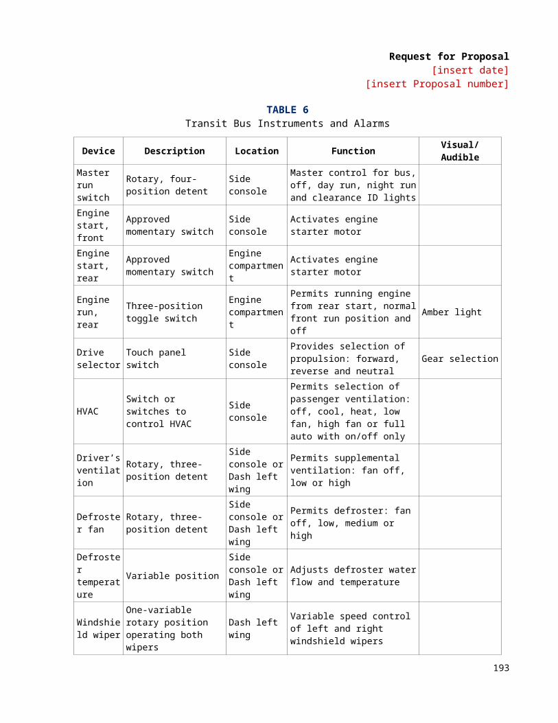
Request for Proposal[insert date]
[insert Proposal number]
TS 79.6 Interior CirculationManeuvering room inside the bus shall accommodate easy travel for a passenger in a wheelchair from the loading device and from the designated securement area. It shall be designed so that no portion of the wheelchair protrudes into the aisle of the bus when parked in the designated parking space(s). When the positions are fully utilized, an aisle space of no less than 20 in. shall be maintained. As a guide, no width dimension should be less than 34 in. Areas requiring 90-degree turns of wheelchairs should have a clearance arc dimension no less than 45 in., and in the parking area where 180-degree turns are expected, space should be clear in a full 60-in.-diameter circle. A vertical clearance of 12 in. above the floor surface should be provided on the outside of turning areas for wheelchair footrest.
SIGNAGE AND COMMUNICATIONTS 80. Destination Signs A destination sign system shall be furnished on the front, on the right side near the front door.
ALTERNATIVERoute sign on the rear of the vehicle.
ALTERNATIVEStreet and Curb Side Route SignThe sign located near the front door shall not block the driver’s critical horizontal line of sight. Display areas of destination signs shall be clearly visible in direct sunlight and/or at night. Parts shall be commercially available.
All signs shall be controlled via a single human-machine interface (HMI). In the absence of a single mobile data terminal (MDT), the HMI shall be conveniently located for the bus driver within reach of the seated driver.
ALTERNATIVEThe sign shall not be located within reach of the seated driver.
The destination sign compartments shall meet the following minimum requirements:
• Compartments shall be designed to prevent condensation and entry of moisture and dirt.• Compartments shall be designed to prevent fogging of both compartment window and glazing on
unit itself.• Access shall be provided to allow cleaning of inside compartment window and unit glazing.• Front window shall have an exterior display area of no less than 8.5 in. high by 56 in. wide.
ALTERNATIVENo active defogging required.
ALTERNATIVERun number sign.
195

Request for Proposal[insert date]
[insert Proposal number]
TS 81. Passenger Information and Advertising TS 81.1 Interior DisplaysProvisions shall be made on the rear of the driver’s barrier or equipment box located on the wheel well for a frame to retain information such as routes and schedules.
Advertising media 11 in. high and 0.09 in. thick shall be retained near the juncture of the bus ceiling and sidewall. The retainers may be concave and shall support the media without adhesives. The media shall be illuminated by the interior light system.
ALTERNATIVENext stop display.
TS 81.2 Exterior DisplaysProvisions shall be made to integrate advertising into the exterior design of the bus. Advertising media, frames or supporting structures shall not detract from the readability of destination signs and signal lights, and shall not compromise passenger visibility. Advertising provisions shall not cause pedestrian hazards or foul automatic bus washing equipment, and shall not cover or interfere with doors, air passages, vehicle fittings, or in any other manner restrict the operation or serviceability of the bus. [Agency to specify placement and dimensions of advertising area.]
TS 82. Passenger Stop Request/Exit Signal DEFAULTUse for Touch Tape Passenger SignalA passenger “stop requested” signal system that complies with applicable ADA requirements defined in 49 CFR, Part 38.37 shall be provided. The system shall consist of a touch tape, chime, and interior sign message. The touch tape shall be accessible to all seated passengers, with provisions for standees. It shall be easily accessible to all passengers, seated or standing. Vertical touch tape shall be provided at each window mullion and adjacent to each wheelchair parking position and priority seating positions.
ALTERNATIVEPull Cord Passenger SignalA passenger “stop requested” signal system that complies with applicable ADA requirements defined in 49 CFR, Part 38.37 shall be provided. The system shall consist of a heavy-duty pull cable, chime and interior sign message. The pull cable shall be located the full length of the bus on the sidewalls at the level where the transom is located. If no transom window is required, the height of the pull cable shall approximate this transom level and shall be no greater than 63 in. as measured from the floor surface. It shall be easily accessible to all passengers, seated or standing. Pull cable(s) shall activate one or more solid state or magnetic proximity switches. At each wheelchair passenger position and at priority seating positions, additional provisions shall be included to allow a passenger in a mobility aid to easily activate the “stop requested” signal.
An auxiliary passenger “stop requested” signal shall be installed at the rear door to provide passengers standing in the rear door/exit area convenient means of activating the signal system. The signal shall be a heavy-duty push button type located in the rear door vicinity. Button shall be clearly identified as “passenger signal.”
196
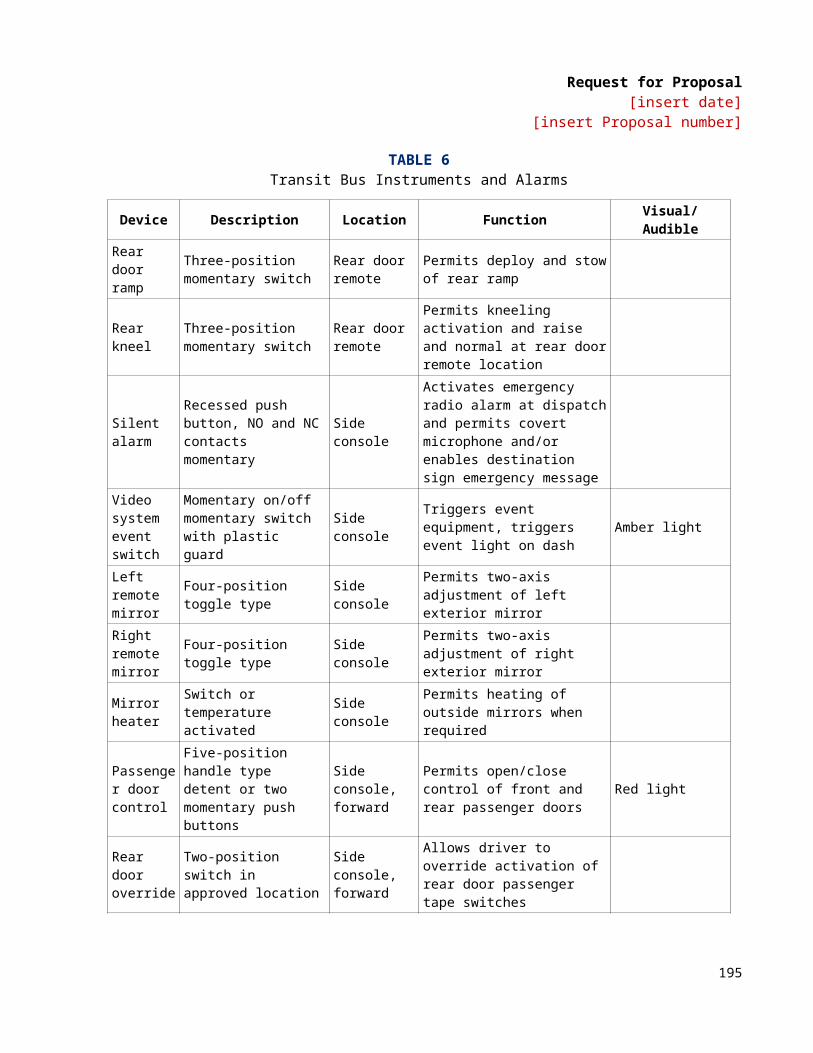
Request for Proposal[insert date]
[insert Proposal number]
DEFAULTNo requirements for additional “stop request” button on rear door stanchion.
ALTERNATIVEAdditional “Stop Request” Button on Rear Door StanchionA heavy-duty “stop request” signal button shall be installed on modesty panel stanchion immediately forward of the rear door and clearly identified as “STOP.”
ALTERNATIVE“Stop request” signal button shall be available at intervals to be determined by the Agency.
A single “stop requested” chime shall sound when the system is first activated. A double chime shall sound anytime the system is activated from wheelchair passenger areas.
Exit signals located in the wheelchair passenger area shall be no higher than 4 feet above the floor. Instructions shall be provided to clearly indicate function and operation of these signals.
ALTERNATIVEPassenger signal system shall be arranged with push button switches accessible by each seated passenger and on stanchions and at rear door locations for standees.
ALTERNATIVEAgency to specify the stop request system for wheelchair seating area
TS 83. CommunicationsTS 83.1 Camera Surveillance System DEFAULTNo surveillance system provisions required.
ALTERNATIVEProvide all wiring and mounting locations for a multi-camera surveillance system for the later provision of and installation of cameras, recorder, microphone, etc. Agency to specify what camera system cable is to be installed, what locations for pre-wiring and the quantity.
ALTERNATIVEProvide all wiring and mounting locations for a multi-camera surveillance system including the installation of cameras, recorder, microphone, etc.
197
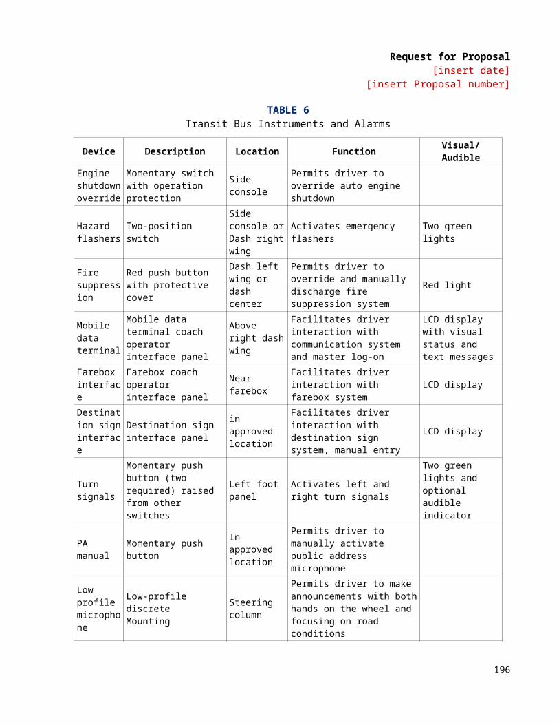
Request for Proposal[insert date]
[insert Proposal number]
TS 83.2 Public Address System A public address system shall be provided on each bus for facilitating radio system and driver-originated announcements to passengers.
TS 83.2.1 Speakers[Agency to specify number] interior loudspeakers shall be provided, semi-flush mounted, on alternate sides of the bus passenger compartment, installed with proper phasing. Total impedance seen at the input connecting end shall be 8 Ohms. Mounting shall be accomplished with riv-nuts and machine screws.
ALTERNATIVEThe speaker cable shall terminate at the instrument panel area on the curb side with a minimum of 3 feet of extra speaker cable. An end connector shall be supplied so a lead can be connected from the radio control head in order to make announcements directly from the transit control center to passengers through the PA system.
TS 83.3 Automatic Passenger Counter (APC)DEFAULTNo APC system shall be installed.
ALTERNATIVEAn infrared APC system shall be installed. [Agency to provide details of APC system including installation locations and number of buses to be equipped]
TS 83.4 Radio Handset and Control SystemTS 83.4.1 Drivers SpeakerEach bus shall have a recessed speaker in the ceiling panel above the driver. This speaker shall be the same component used for the speakers in the passenger compartment. It shall have 8 Ohms of impedance.
TS 83.4.2 HandsetContractor will install a handset for driver use.
TS 83.4.3 Driver Display Unit (DDU)Contractor shall install a driver display unit as close to the driver’s instrument panel as possible.
TS 83.4.4 Emergency AlarmContractor shall install an emergency alarm that is accessible to the driver but hidden from view.
198
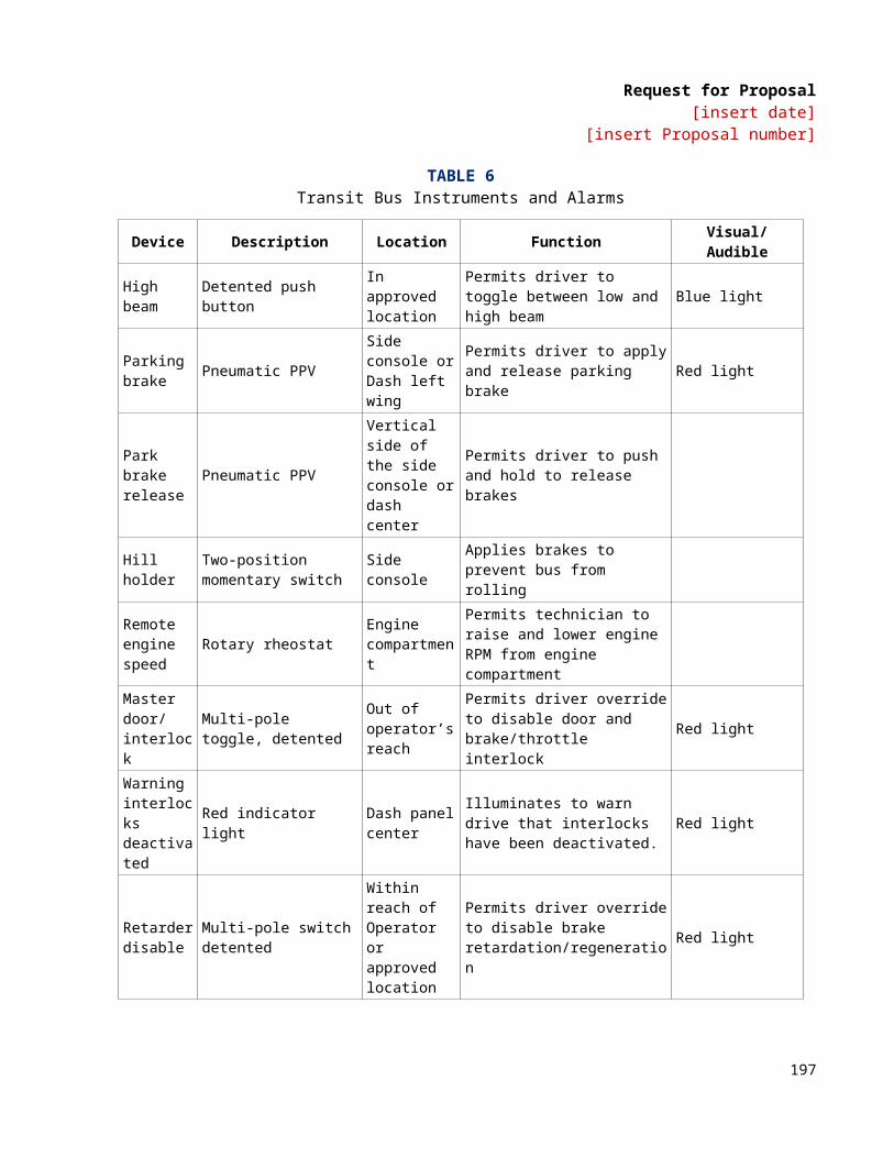
Request for Proposal[insert date]
[insert Proposal number]
SECTION 7: WARRANTY REQUIREMENTS
WR 1. Basic ProvisionsWR 1.1 Warranty RequirementsWR 1.1.1 Contractor WarrantyWarranties in this document are in addition to any statutory remedies or warranties imposed on the Contractor. Consistent with this requirement, the Contractor warrants and guarantees to the original Agency each complete bus and specific subsystems and components as follows. Performance requirements based on design criteria shall not be deemed a warranty item.
WR 1.1.2 Complete BusThe complete bus, propulsion system, components, major subsystems and body and chassis structure are warranted to be free from Defects and Related Defects for one year or 50,000 miles, whichever comes first, beginning on the date of revenue service but not longer than 15 days after acceptance under “Inspection, Testing and Acceptance.” The warranty is based on regular operation of the bus under the operating conditions prevailing in the Agency’s locale.
WR 1.1.3 Body and Chassis StructureBody, body structure, structural elements of the suspension and engine cradle are warranted to be free from Defects and Related Defects for three years or 150,000 miles, whichever comes first.
Primary load-carrying members of the bus structure, including structural elements of the suspension, are warranted against corrosion failure and/or Fatigue Failure sufficient to cause a Class 1 or Class 2 Failure for a period of 12 years or 500,000 miles, whichever comes first.
WR 1.1.4 Propulsion SystemPropulsion system components, specifically the engine, transmission or drive motors, and generators (for hybrid technology) and drive and non-drive axles shall be warranted to be free from Defects and Related Defects for the standard two years or 100,000 miles, whichever comes first. An Extended Warranty to a maximum of five years or 300,000 miles, whichever comes first, may be purchased at an additional cost. The propulsion system manufacturer’s standard warranty, delineating items excluded from the Extended Warranty, submitted in accordance with the Request for Pre-Offer Change or Approved Equal or with the Form for Proposal Deviation.
WR 1.1.5 Emission Control System (ECS)The Contractor warrants the emission control system for five years or 100,000 miles, whichever comes first. The ECS shall include, but is not limited to, the following components:
• complete exhaust system, including catalytic converter (if required)• after-treatment device• components identified as emission control devices
199
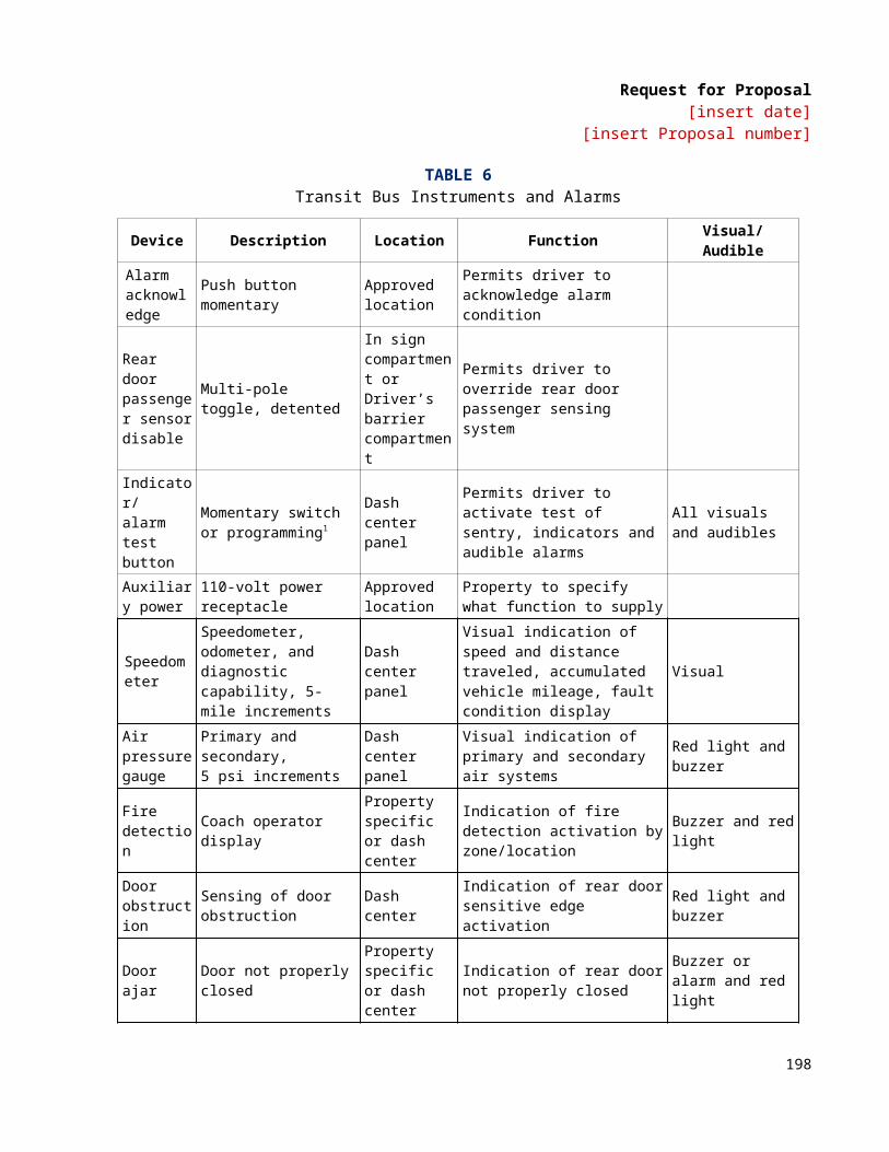
Request for Proposal[insert date]
[insert Proposal number]
WR 1.1.6 SubsystemsOther subsystems shall be warranted to be free from Defects and Related Defects for two years or 100,000 miles, whichever comes first. Other subsystems are listed below:
• Brake system: Foundation brake components, including advancing mechanisms, as supplied with the axles, excluding friction surfaces.
• Destination signs: All destination sign equipment for the front, side and rear signs, power modules and operator control.
• Heating, ventilating: Roof and/or rear main unit only, excluding floor heaters and front defroster. • AC unit and compressor: Roof and/or rear main unit only, excluding floor heaters and front defroster. • Door systems: Door operating actuators and linkages. • Air compressor • Air dryer • Wheelchair lift and ramp system: Lift and/or ramp parts and mechanical only • Starter • Alternator: Alternator only. Does not include the drive system. • Charge air cooler: Charge air cooler including core, tanks and including related surrounding
framework and fittings. • Fire suppression: Fire suppression system including tank and extinguishing agent dispensing system • Hydraulic systems: Including radiator fan drive and power steering as applicable. • Engine cooling systems: Radiator including core, tanks and related framework, including surge tank. • Transmission cooler • Passenger seating excluding upholstery • Fuel storage and delivery system • Surveillance system including cameras and video recorders
WR 1.1.7 Extended WarrantyThe Agency requires the following additional subsystems to be warranted to be free from Defects and Related Defects for two years or 100,000 miles, whichever comes first.
• [insert as appropriate]• [insert as appropriate]• [insert as appropriate]
WR 1.1.8 Serial NumbersUpon delivery of each bus, the Contractor shall provide a complete electronic list of serialized units installed on each bus to facilitate warranty tracking. The list shall include, but is not limited to:
• engine• transmission• alternator• starter• A/C compressor and condenser/evaporator unit• drive axle• power steering unit• fuel cylinders (if applicable)• air compressor• wheelchair ramp (if applicable)
200

Request for Proposal[insert date]
[insert Proposal number]
The Contractor shall provide updated serial numbers resulting from warranty campaigns. The format of the list shall be approved by the Agency prior to delivery of the first production bus.
WR 1.1.9 Extension of WarrantyIf, during the warranty period, repairs or modifications on any bus are made necessary by defective design, materials or workmanship but are not completed due to lack of material or inability to provide the proper repair for thirty (30) calendar days, the applicable warranty period shall be extended by the number of days equal to the delay period.
WR 1.2 Voiding of Warranty The warranty shall not apply to the failure of any part or component of the bus that directly results from misuse, negligence, accident or repairs not conducted in accordance with the Contractor-provided maintenance manuals and with workmanship performed by adequately trained personnel in accordance with recognized standards of the industry. The warranty also shall be void if the Agency fails to conduct normal inspections and scheduled preventive maintenance procedures as recommended in the Contractor’s maintenance manuals and if that omission caused the part or component failure. The Agency shall maintain documentation, auditable by the Contractor, verifying service activities in conformance with the Contractor’s maintenance manuals.
WR 1.3 Exceptions and Additions to Warranty The warranty shall not apply to the following items:
• scheduled maintenance items• normal wear-out items • items furnished by the Agency
Should the Agency require the use of a specific product and has rejected the Contractor’s request for an alternate product, then the standard Supplier warranty for that product shall be the only warranty provided to the Agency. This product will not be eligible under “Fleet Defects,” below.
The Contractor shall not be required to provide warranty information for any warranty that is less than or equal to the warranty periods listed.
WR 1.3.1 Pass-Through WarrantyShould the Contractor elect to not administer warranty claims on certain components and wish to transfer this responsibility to the sub-Suppliers, or to others, the Contractor shall request this waiver.
Contractor shall state in writing that the Agency’s warranty reimbursements will not be impacted. The Contractor also shall state in writing any exceptions and reimbursement including all costs incurred in transport of vehicles and/or components. At any time during the warranty period, the Contractor may request approval from the Agency to assign its warranty obligations to others, but only on a case-by-case basis approved in writing by the Agency. Otherwise, the Contractor shall be solely responsible for the administration of the warranty as specified. Warranty administration by others does not eliminate the warranty liability and responsibility of the Contractor.
201
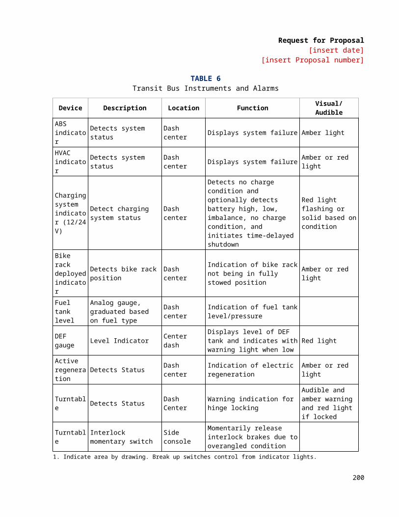
Request for Proposal[insert date]
[insert Proposal number]
WR 1.3.2 Superior WarrantyThe Contractor shall pass on to the Agency any warranty offered by a component Supplier that is superior to that required herein. The Contractor shall provide a list to the Agency noting the conditions and limitations of the Superior Warranty not later than the start of production. The Superior Warranty shall not be administered by the Contractor.
WR 1.4 Fleet Defects WR 1.4.1 Occurrence and RemedyA Fleet Defect is defined as cumulative failures of twenty-five (25) percent of the same components in the same or similar application in a minimum fleet size of twelve (12) or more buses where such items are covered by warranty. A Fleet Defect shall apply only to the base warranty period in sections entitled “Complete Bus,” “Propulsion System” and “Major Subsystems.” When a Fleet Defect is declared, the remaining warranty on that item/component stops. The warranty period does not restart until the Fleet Defect is corrected.
For the purpose of Fleet Defects, each option order shall be treated as a separate bus fleet. In addition, should there be a change in a major component within either the base order or an option order, the buses containing the new major component shall become a separate bus fleet for the purposes of Fleet Defects.
The Contractor shall correct a Fleet Defect under the warranty provisions defined in “Repair Procedures.” After correcting the Defect, the Agency and the Contractor shall mutually agree to and the Contractor shall promptly undertake and complete a work program reasonably designed to prevent the occurrence of the same Defect in all other buses and spare parts purchased under this Contract. Where the specific Defect can be solely attributed to particular identifiable part(s), the work program shall include redesign and/or replacement of only the defectively designed and/or manufactured part(s). In all other cases, the work program shall include inspection and/or correction of all of the buses in the fleet via a mutually agreed-to arrangement. The Contractor shall update, as necessary, technical support information (parts, service and operator’s manuals) due to changes resulting from warranty repairs. The Agency may immediately declare a Defect in design resulting in a safety hazard to be a Fleet Defect. The Contractor shall be responsible to furnish, install and replace all defective units.
WR 1.4.2 Exceptions to Fleet Defect ProvisionsThe Fleet Defect warranty provisions shall not apply to Agency-supplied items, such as radios, fare collection equipment, communication systems and tires. In addition, Fleet Defects shall not apply to interior and exterior finishes, hoses, fittings and fabric.
WR 2. Repair ProceduresWR 2.1 Repair Performance The Contractor is responsible for all warranty-covered repair Work. To the extent practicable, the Agency will allow the Contractor or its designated representative to perform such Work. At its discretion, the Agency may perform such Work if it determines it needs to do so based on transit service or other requirements. Such Work shall be reimbursed by the Contractor.
WR 2.2 Repairs by the Contractor If the Agency detects a Defect within the warranty periods defined in this section, it shall, within thirty (30) days, notify the Contractor’s designated representative. The Contractor or its designated representative shall,
202

Request for Proposal[insert date]
[insert Proposal number]
if requested, begin Work on warranty-covered repairs within five calendar days after receiving notification of a Defect from the Agency. The Agency shall make the bus available to complete repairs timely with the Contractor’s repair schedule.
The Contractor shall provide at its own expense all spare parts, tools and space required to complete repairs. At the Agency’s option, the Contractor may be required to remove the bus from the Agency’s property while repairs are being affected. If the bus is removed from the Agency’s property, repair procedures must be diligently pursued by the Contractor’s representative.
WR 2.3 Repairs by the Agency WR 2.3.1 Parts UsedIf the Agency performs the warranty-covered repairs, it shall correct or repair the Defect and any Related Defects utilizing parts supplied by the Contractor specifically for this repair. At its discretion, the Agency may use Contractor-specified parts available from its own stock if deemed in its best interests.
WR 2.3.2 Contractor-Supplied PartsThe Agency may require that the Contractor supply parts for warranty-covered repairs being performed by the Agency. Those parts may be remanufactured but shall have the same form, fit and function, and warranty. The parts shall be shipped prepaid to the Agency from any source selected by the Contractor within fourteen (14) days of receipt of the request for said parts and shall not be subject to an Agency handling charge.
WR 2.3.3 Defective Component ReturnThe Contractor may request that parts covered by the warranty be returned to the manufacturing plant. The freight costs for this action shall be paid by the Contractor. Materials should be returned in accordance with the procedures outlined in “Warranty Processing Procedures.”
WR 2.3.4 Failure AnalysisThe Contractor shall, upon specific request of the Agency, provide a failure analysis of Fleet Defect or safety-related parts, or major components, removed from buses under the terms of the warranty that could affect fleet operation. Such reports shall be delivered within 60 days of the receipt of failed parts.
WR 2.3.5 Reimbursement for Labor and Other Related CostsThe Agency shall be reimbursed by the Contractor for labor. The amount shall be determined by the Agency for a qualified mechanic at a straight time wage rate of [insert amount] per hour, which includes fringe benefits and overhead adjusted for the Agency’s most recently published rate in effect at the time the Work is performed, plus the cost of towing the bus if such action was necessary and if the bus was in the normal service area. These wage and fringe benefit rates shall not exceed the rates in effect in the Agency’s service garage at the time the Defect correction is made.
WR 2.3.6 Reimbursement for PartsThe Agency shall be reimbursed by the Contractor for defective parts and for parts that must be replaced to correct the Defect. The reimbursement shall be at the current price at the time of repair and shall include taxes where applicable, plus fifteen (15) percent handling costs. Handling costs shall not be paid if part is supplied by Contractor and shipped to Agency.
203
Request for Proposal[insert date]
[insert Proposal number]
WR 2.3.7 Reimbursement RequirementsThe Contractor shall respond to the warranty claim with an accept/reject decision including necessary failure analysis no later than sixty (60) days after the Agency submits the claim and defective part(s), when requested. Reimbursement for all accepted claims shall occur no later than sixty (60) days from the date of acceptance of a valid claim. The Agency may dispute rejected claims or claims for which the Contractor did not reimburse the full amount. The parties agree to review disputed warranty claims during the following quarter to reach an equitable decision to permit the disputed claim to be resolved and closed. The parties also agree to review all claims at least once per quarter throughout the entire warranty period to ensure that open claims are being tracked and properly dispositioned.
WR 2.4 Warranty after Replacement/Repairs If any component, unit or subsystem is repaired, rebuilt or replaced by the Contractor or by the Agency with the concurrence of the Contractor, the component, unit or subsystem shall have the unexpired warranty period of the original. Repairs shall not be warranted if the Contractor-provided or authorized parts are not used for the repair, unless the Contractor has failed to respond within five days, in accordance with “Repairs by the Contractor.”
If an item is declared to be a Fleet Defect, the warranty stops with the declaration of the Fleet Defect. Once the Fleet Defect is corrected, the item(s) shall have three (3) months or remaining time and/or miles of the original warranty, whichever is greater. This remaining warranty period shall begin on the repair/replacement date for corrected items on each bus if the repairs are completed by the Contractor or on the date the Contractor provides all parts to the Agency.
WR 2.4.1 Warranty Processing ProceduresThe following list represents requirements by the Contractor to the Agency for processing warranty claims. One failure per bus per claim is allowed.
• bus number and VIN • total vehicle life mileage at time of repair• date of failure/repair• acceptance/in-service date• Contractor part number and description• component serial number • description of failure• all costs associated with each failure/repair (invoices may be required for third-party costs):
• towing • road calls• labor• materials• parts• handling• troubleshooting time
WR 2.5 Forms The Agency’s forms will be accepted by the Contractor if all of the above information is included. Electronic submittal may be used if available between the Contractor and Agency.
204

Request for Proposal[insert date]
[insert Proposal number]
WR 2.6 Return of Parts When returning defective parts to the Contractor, the Agency shall tag each part with the following:
• bus number and VIN• claim number• part number• serial number (if available)
WR 2.7 Timeframe Each claim must be submitted no more than thirty (30) days from the date of failure and/or repair, whichever is later. All defective parts must be returned to the Contractor, when requested, no more than forty-five (45) days from date of repair.
WR 2.8 Reimbursements Reimbursements are to be transmitted to the following address.
[Agency to insert address where check is to be sent]
205

Request for Proposal[insert date]
[insert Proposal number]
SECTION 8: QUALITY ASSURANCE
QA 1. Contractor’s In-Plant Quality Assurance RequirementsQA 1.1 Quality Assurance Organization QA 1.1.1 Organization EstablishmentThe Contractor shall establish and maintain an effective in-plant quality assurance organization. It shall be a specifically defined organization and should be directly responsible to the Contractor’s top management.
QA 1.1.2 ControlThe quality assurance organization shall exercise quality control over all phases of production, from initiation of design through manufacture and preparation for delivery. The organization shall also control the quality of supplied articles.
QA 1.1.3 Authority and ResponsibilityThe quality assurance organization shall have the authority and responsibility for reliability, quality control, inspection planning, establishment of the quality control system, and acceptance/rejection of materials and manufactured articles in the production of the transit buses.
QA 1.2 Quality Assurance Organization FunctionsQA 1.2.1 Minimum FunctionsThe quality assurance organization shall include the following minimum functions:
• Work instructions: The quality assurance organization shall verify inspection operation instructions to ascertain that the manufactured product meets all prescribed requirements.
• Records maintenance: The quality assurance organization shall maintain and use records and data essential to the effective operation of its program. These records and data shall be available for review by the resident inspectors. Inspection and test records for this procurement shall be available for a minimum of one year after inspections and tests are completed.
• Corrective action: The quality assurance organization shall detect and promptly ensure correction of any conditions that may result in the production of defective transit buses. These conditions may occur in designs, purchases, manufacture, tests or operations that culminate in defective supplies, services, facilities, technical data or standards.
QA 1.2.2 Basic Standards and FacilitiesThe following standards and facilities shall be basic in the quality assurance process:
• Configuration control: The Contractor shall maintain drawings, assembly procedures, and other documentation that completely describe a qualified bus that meets all of the options and special requirements of this procurement. The quality assurance organization shall verify that each transit bus is manufactured in accordance with these controlled drawings, procedures, and documentation.
• Measuring and testing facilities: The Contractor shall provide and maintain the necessary gauges and other measuring and testing devices for use by the quality assurance organization to verify that the buses conform to all specification requirements. These devices shall be calibrated at established
206
Request for Proposal[insert date]
[insert Proposal number]
periods against certified measurement standards that have known, valid relationships to national standards.
• Production tooling as media of inspection: When production jigs, fixtures, tooling masters, templates, patterns, and other devices are used as media of inspection, they shall be proved for accuracy at formally established intervals and adjusted, replaced, or repaired as required to maintain quality.
• Equipment use by resident inspectors: The Contractor’s gauges and other measuring and testing devices shall be made available for use by the resident inspectors to verify that the buses conform to all specification requirements. If necessary, the Contractor’s personnel shall be made available to operate the devices and to verify their condition and accuracy.
QA 1.2.3 Maintenance of ControlThe Contractor shall maintain quality control of purchases:
• Supplier control: The Contractor shall require that each Supplier maintains a quality control program for the services and supplies that it provides. The Contractor’s quality assurance organization shall inspect and test materials provided by Suppliers for conformance to specification requirements. Materials that have been inspected, tested, and approved shall be identified as acceptable to the point of use in the manufacturing or assembly processes. Controls shall be established to prevent inadvertent use of nonconforming materials.
• Purchasing data: The Contractor shall verify that all applicable specification requirements are properly included or referenced in purchase orders of articles to be used on transit buses.
QA 1.2.4 Manufacturing Control• Controlled conditions: The Contractor shall ensure that all basic production operations, as well as all
other processing and fabricating, are performed under controlled conditions. Establishment of these controlled conditions shall be based on the documented Work instructions, adequate production equipment and special working environments if necessary.
• Completed items: A system for final inspection and test of completed transit buses shall be provided by the quality assurance organization. It shall measure the overall quality of each completed bus.
• Nonconforming materials: The quality assurance organization shall monitor the Contractor’s system for controlling nonconforming materials. The system shall include procedures for identification, segregation and disposition.
• Statistical techniques: Statistical analysis, tests and other quality control procedures may be used when appropriate in the quality assurance processes.
• Inspection status: A system shall be maintained by the quality assurance organization for identifying the inspection status of components and completed transit buses. Identification may include cards, tags or other normal quality control devices.
QA 1.2.5 Inspection SystemThe quality assurance organization shall establish, maintain and periodically audit a fully documented inspection system. The system shall prescribe inspection and test of materials, Work in process and completed articles. As a minimum, it shall include the following controls:
• Inspection personnel: Sufficient trained inspectors shall be used to ensure that all materials, components and assemblies are inspected for conformance with the qualified bus design.
• Inspection records: Acceptance, rework or rejection identification shall be attached to inspected articles. Articles that have been accepted as a result of approved materials review actions shall be identified. Articles that have been reworked to specified drawing configurations shall not require
207
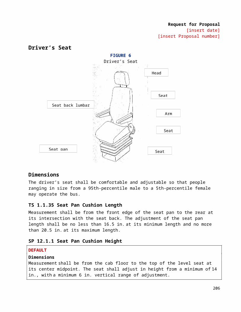
Request for Proposal[insert date]
[insert Proposal number]
special identification. Articles rejected as unsuitable or scrap shall be plainly marked and controlled to prevent installation on the bus. Articles that become obsolete as a result of engineering changes or other actions shall be controlled to prevent unauthorized assembly or installation. Unusable articles shall be isolated and then scrapped. Discrepancies noted by the Contractor or resident inspectors during assembly shall be entered by the inspection personnel on a record that accompanies the major component, subassembly, assembly, or bus from start of assembly through final inspection. Actions shall be taken to correct discrepancies or deficiencies in the manufacturing processes, procedures or other conditions that cause articles to be in nonconformity with the requirements of the Contract specifications. The inspection personnel shall verify the corrective actions and mark the discrepancy record. If discrepancies cannot be corrected by replacing the nonconforming materials, then the Agency shall approve the modification, repair or method of correction to the extent that the Contract specifications are affected.
• Quality assurance audits: The quality assurance organization shall establish and maintain a quality control audit program. Records of this program shall be subject to review by the Agency.
QA 2. InspectionQA 2.1 Inspection StationsInspection stations shall be at the best locations to provide for the Work content and characteristics to be inspected. Stations shall provide the facilities and equipment to inspect structural, electrical, hydraulic and other components and assemblies for compliance with the design requirements.
Stations shall also be at the best locations to inspect or test characteristics before they are concealed by subsequent fabrication or assembly operations. These locations shall minimally include underbody structure completion, body framing completion, body prior to paint preparation, water test, engine installation completion, underbody dress-up and completion, bus prior to final paint touchup, bus prior to road test and bus final road test completion.
QA 2.2 Resident InspectorsQA 2.2.1 Resident Inspector’s RoleThe Agency shall be represented at the Contractor’s plant by resident inspectors, as required by FTA. Resident inspectors may be Agency employees or outside contractors. The Agency shall provide the identify of each inspector and shall also identify their level of authority in writing. They shall monitor, in the Contractor’s plant, the manufacture of transit buses built under the procurement. The presence of these resident inspectors in the plant shall not relieve the Contractor of its responsibility to meet all of the requirements of this procurement. The Agency shall designate a primary resident inspector, whose duties and responsibilities are delineated in “Pre-Production Meetings,” “Authority” and “Pre-Delivery Tests,” below. Contractor and resident inspector relations shall be governed by the guidelines included as Attachment A to this “Section 8: Quality Assurance.”
QA 2.2.2 Pre-Production MeetingsThe primary resident inspector may participate in design review and pre-production meetings with the Agency. At these meetings, the configuration of the buses and the manufacturing processes shall be finalized, and all Contract documentation provided to the inspector.
No less than thirty (30) days prior to the beginning of bus manufacture, the primary resident inspector may meet with the Contractor’s quality assurance manager and may conduct a pre-production audit meeting. They
208
Request for Proposal[insert date]
[insert Proposal number]
shall review the inspection procedures and finalize inspection checklists. The resident inspectors may begin monitoring bus construction activities two weeks prior to the start of bus fabrication.
QA 2.2.3 AuthorityRecords and data maintained by the quality assurance organization shall be available for review by the resident inspectors. Inspection and test records for this procurement shall be available for a minimum of one year after inspections and tests are completed.
The Contractor’s gauges and other measuring and testing devices shall be made available for use by the resident inspectors to verify that the buses conform to all specification requirements. If necessary, the Contractor’s personnel shall be made available to operate the devices and to verify their condition and accuracy.
Discrepancies noted by the resident inspector during assembly shall be entered by the Contractor’s inspection personnel on a record that accompanies the major component, subassembly, assembly or bus from start of assembly through final inspection. Actions shall be taken to correct discrepancies or deficiencies in the manufacturing processes, procedures or other conditions that cause articles to be in nonconformity with the requirements of the Contract specifications. The inspection personnel shall verify the corrective actions and mark the discrepancy record. If discrepancies cannot be corrected by replacing the nonconforming materials, the Agency shall approve the modification, repair or method of correction to the extent that the Contract specifications are affected.
The primary resident inspector shall remain in the Contractor’s plant for the duration of bus assembly Work under this Contract. Only the primary resident inspector or designee shall be authorized to release the buses for delivery. The resident inspectors shall be authorized to approve the pre-delivery acceptance tests. Upon request to the quality assurance supervisors, the resident inspectors shall have access to the Contractor’s quality assurance files related to this procurement. These files shall include drawings, assembly procedures, material standards, parts lists, inspection processing and reports, and records of Defects.
QA 2.2.4 Support ProvisionsThe Contractor shall provide office space for the resident inspectors in close proximity to the final assembly area. This office space shall be equipped with desks, outside and interplant telephones, Internet access, file cabinet and chairs.
QA 2.2.5 Compliance with Safety RequirementsAt the time of the Pre-Production meeting, the Contractor shall provide all safety and other operational restrictions that govern the Contractor’s facilities. These issues will be discussed and the parties will agree which rules/restrictions will govern the Agency’s inspector(s) and any other Agency representatives during the course of the Contract.
QA 3. Acceptance TestsQA 3.1 ResponsibilityFully documented tests shall be conducted on each production bus following manufacture to determine its acceptance to the Agency. These acceptance tests shall include pre-delivery inspections and testing by the Contractor and inspections and testing by the Agency after the buses have been delivered.
209
Request for Proposal[insert date]
[insert Proposal number]
QA 3.2 Pre-Delivery TestsThe Contractor shall conduct acceptance tests at its plant on each bus following completion of manufacture and before delivery to the Agency. These pre-delivery tests shall include visual and measured inspections, as well as testing the total bus operation. The tests shall be conducted and documented in accordance with written test plans approved by the Agency.
Additional tests may be conducted at the Contractor’s discretion to ensure that the completed buses have attained the required quality and have met the requirements in Section 6: Technical Specifications. The Agency may, prior to commencement of production, demand that the Contractor demonstrate compliance with any requirement in that section if there is evidence that prior tests have been invalidated by the Contractor’s change of Supplier or change in manufacturing process. Such demonstration shall be by actual test, or by supplying a report of a previously performed test on similar or like components and configuration. Any additional testing shall be recorded on appropriate test forms provided by the Contractor and shall be conducted before acceptance of the bus.
The pre-delivery tests shall be scheduled and conducted with thirty (30) days notice so that they may be witnessed by the resident inspectors, who may accept or reject the results of the tests. The results of pre-delivery tests, and any other tests, shall be filed with the assembly inspection records for each bus. The underfloor equipment shall be available for inspection by the resident inspectors, using a pit or bus hoist provided by the Contractor. A hoist, scaffold or elevated platform shall be provided by the Contractor to easily and safely inspect bus roofs. Delivery of each bus shall require written authorization of the primary resident inspector. Authorization forms for the release of each bus for delivery shall be provided by the Contractor. An executed copy of the authorization shall accompany the delivery of each bus.
QA 3.2.1 Visual and Measured InspectionsVisual and measured inspections shall be conducted with the bus in a static condition. The purpose of the inspection testing includes verification of overall dimension and weight requirements, that required components are included and are ready for operation, and that components and subsystems designed to operate with the bus in a static condition do function as designed.
QA 3.2.2 Total Bus OperationTotal bus operation shall be evaluated during road tests. The purpose of the road tests is to observe and verify the operation of the bus as a system and to verify the functional operation of the subsystems that can be operated only while the bus is in motion.
Each bus shall be driven for a minimum of fifteen (15) miles during the road tests. If requested, computerized diagnostic printouts showing the performance of each bus shall be produced and provided to the Agency. Observed Defects shall be recorded on the test forms. The bus shall be retested when Defects are corrected and adjustments are made. This process shall continue until Defects or required adjustments are no longer detected.
QA 4. Agency-Specific Requirements[Agency to insert as required]
210
Request for Proposal[insert date]
[insert Proposal number]
ATTACHMENT A: NEW BUS MANUFACTURING INSPECTION GUIDELINES
Pre-production meetingResponsibilities Agency
• Provides conformed copy of technical requirements.• Recommended staff to be involved may include the following:
• Project manager• Technical engineer• Contract administrator• Quality assurance administrator• Warranty administrator
• Process for inspector’s role (to deal with agency) for negotiated changes after freeze date.• Contractual requirements:
• Milestones• Documentation • Title requirements• Deliverables• Payments • Reliability tracking
Manufacturer• Identifies any open issues.• Recommended staff to be involved may include the following:
• Project manager• Technical engineer(s)• Contract administrator• Quality assurance administrator• Warranty administrator
• Production flow (buses/week, shifts).• Delivery schedule and offsite component build-up schedule.• Bus QA documentation (including supplier application approvals and/or any certifications required
for the specific production).• Communication flow/decision making.
Inspector• Agree on decisions inspectors can and cannot make.• Primary contact for problems, etc.• Production flow process (description of manufacturing by station).• Factory hours (manage inspection schedule based on production hours).• Plant rules.• Safety requirements.• Orientation requirements.• Work environment.• Inspector’s office space (per contract).
211
Request for Proposal[insert date]
[insert Proposal number]
NOTE: As a result of this meeting, documentation should be produced detailing final production requirements and the planned configuration of the bus.
Build scheduleThe bus manufacturer’s contract administrator shall supply a fleet build production schedule based on the dates in the Notice to Proceed, and a description of the manufacturer’s schedule for plant operations.
The production schedule should contain specific milestone dates, such as:
• First vehicle on production line (date on which any work will begin);• First vehicle off production line;• First vehicle through manufacturer’s quality assurance inspections;• First vehicle shipped to the agency;• Last vehicle on production line;• Last vehicle off production line; and• Last vehicle shipped to the agency.
Plant tour (if meeting at OEM’s location)The agency will review the entire process from start to finish and review the work completed at each line station, including quality control measures
Prototype/pilot vehicle productionThe contractor shall conduct acceptance tests at its plant on each bus following completion of manufacture and before delivery to the agency. These pre-delivery tests shall include visual and measured inspections, as well as testing the total bus operation. The tests shall be conducted and documented in accordance with written test plans approved by the agency. The underfloor equipment shall be available for inspection by the resident inspectors, using a pit or bus hoist provided by the contractor. A hoist, scaffold or elevated platform shall be provided by the contractor to easily and safely inspect bus roofs. Delivery of each bus shall require written authorization of the primary resident inspector. Authorization forms for the release of each bus for delivery shall be provided by the contractor. An executed copy of the authorization shall accompany the delivery of each bus.
Additional tests may be conducted at the agency’s discretion to ensure that the completed buses have attained the required quality and have met the requirements in the APTA “Standard Bus Procurement Guidelines RFP,” Section 6: Technical Specifications. The agency may, prior to commencement of production, demand that the contractor demonstrate compliance with any requirement in that section if there is evidence that prior tests have been invalidated by the contractor’s change of supplier or change in manufacturing process. Such demonstration shall be by actual test, or by supplying a report of a previously performed test on similar or like components and configuration. Any additional testing shall be recorded on appropriate test forms provided by the contractor and shall be conducted before acceptance of the bus.
The pre-delivery tests shall be scheduled and conducted with 30 days’ notice so that they may be witnessed by the resident inspectors, who may accept or reject the results of the tests. The results of pre-delivery tests, and any other tests, shall be filed with the assembly inspection records for each bus.
212
Request for Proposal[insert date]
[insert Proposal number]
Visual and measured inspectionsVisual and measured inspections shall be conducted with the bus in a static condition. The purpose of the inspection testing includes verification of overall dimension and weight requirements, that required components are included and are ready for operation, and that components and subsystems designed to operate with the bus in a static condition do function as designed.
Total bus operationTotal bus operation shall be evaluated during road tests. The purpose of the road tests is to observe and verify the operation of the bus as a system and to verify the functional operation of the subsystems that can be operated only while the bus is in motion.
Each bus shall be driven for a minimum of 15 miles during the road tests. If requested, computerized diagnostic printouts showing the performance of each bus shall be produced and provided to the agency. Observed defects shall be recorded on the test forms. The bus shall be retested when defects are corrected and adjustments are made. This process shall continue until defects or required adjustments are no longer detected.
Post-delivery testsThe agency shall conduct acceptance tests on each delivered bus. These tests shall be completed within 15 days after bus delivery and shall be conducted in accordance with the agency’s written test plans. The purpose of these tests is to identify defects that have become apparent between the time of bus release and delivery to the agency. The post-delivery tests shall include visual inspection and bus operations. No post-delivery test shall apply new criteria that are different from criteria applied in a pre-delivery test.
Buses that fail to pass the post-delivery tests are subject to non-acceptance. The agency shall record details of all defects on the appropriate test forms and shall notify the contractor of acceptance or non-acceptance of each bus, after completion of the tests. The defects detected during these tests shall be repaired according to procedures defined in the contract.
Prototype/pilot vehicle acceptance In order to assess the contractor’s compliance with the Technical Specifications, the agency and the contractor shall, at the pre-production meeting, jointly develop a Configuration and Performance Review document for review of the pilot vehicle. This document shall become part of the official record of the pre-production meeting.
Potential dimensional/performance tests that may be included in the Configuration and Performance Review include the following:
• Complete electrical system audit• Dimensional requirements audit• Seating capacity• Water test• Water runoff test• Function test of systems/subsystems and components• Sound/noise level tests• Vehicle top speed• Acceleration tests
213

Request for Proposal[insert date]
[insert Proposal number]
• Brake stop tests• Airflow tests• PA function tests• Air/brake system audit• Individual axle weight • Standee capacity• Body deflection tests• Silent alarm function test• Interior lighting• Exterior lighting• Gradability test• Kneeling system function• HVAC pulldown/heat• Speedometer• Outside air infiltration (smoke)• Wheelchair ramps• Engine performance qualification
• This test shall be jointly conducted by the contractor and engine manufacturer (including but not limited to charge air cooler performance, air to boil test, loss of coolant, fuel system electrical inputs and engine protection system).
• Transmission performance qualifications• This test shall be jointly conducted by the Contractor and transmission manufacturer (including but not limited to retarder operation, heat exchanger, interface with ABS and electrical inputs).
Buy America auditA post-delivery Buy America audit is required for federally funded bus procurements (see 49 CFR Part 663 for additional information). The onsite resident inspectors are to monitor the production processes to verify compliance with final assembly requirements identified by the Buy America pre-award audit. This audit is to verify compliance with final assembly requirements and final documentation of Buy America compliance and must be completed prior to title transfer.
NOTE: If there is not a pilot/prototype bus, then the Buy America post-delivery audit should be performed following completion of the first serial production bus. In addition to monitoring of the production processes, the agency must verify compliance that more than 60 percent of the costs of all components are produced in the United States. Finally, the agency must execute the required certificates.
Resident inspection process for serial productionAt the discretion of the agency, a decision is made to perform resident inspection using the agency’s personnel, a contract inspector, or a combination of both. The decision is based on factors such as the availability of personnel, knowledge/expertise in bus build project management, the size of the bus order, etc.
NOTE: The decision to have the resident inspection performed by agency personnel results in a firm understanding and knowledge of the bus and affords the opportunity to identify parts that will be needed for general maintenance down the road.
214
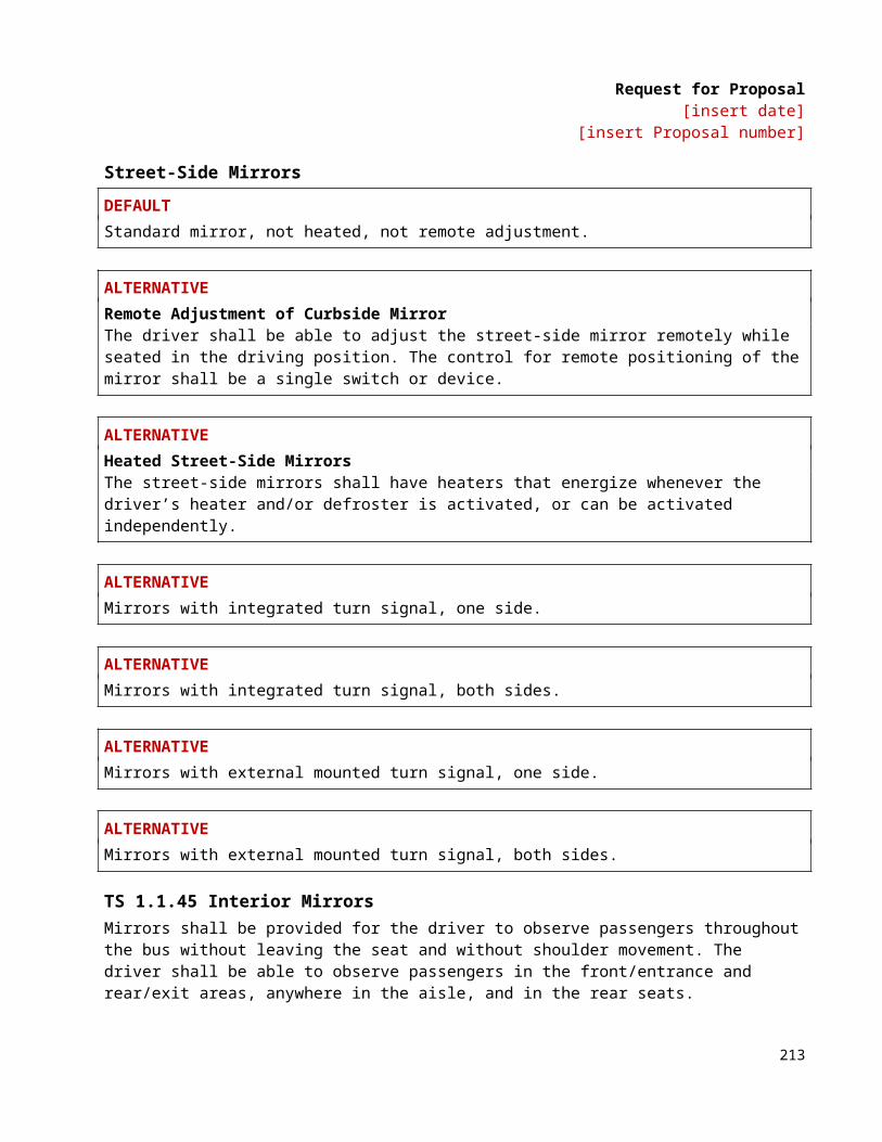
Request for Proposal[insert date]
[insert Proposal number]
Inspector responsibilitiesThe resident inspection process for the serial production of the buses begins following the completion and acceptance of the prototype or pilot vehicle if required, or according to the serial bus production schedule. Resident inspectors should represent the agency for all build-related issues (quality, conformance, etc.). Resident inspectors can also address contractual type issues but should only do so under the consult of the agency’s contracts administrator. Resident inspectors are sent to the manufacturer’s facility according to a Resident Inspection Schedule. Typically, one or two inspectors arrive on site at the manufacturing facility about one week prior to actual production to set up the resident inspection process and to begin preliminary quality assurance inspections for items such as power plant build-up and wire harness production, and to inspect incoming parts, fasteners, fluids, etc., that will be used in the production of the buses. During the serial production of the buses, the resident inspectors should monitor the production of each bus, verifying the quality of materials, components, sub-assemblies and manufacturing standards. In addition, the configuration of each vehicle should be audited using the vehicle manufacturer’s Build Specification and other documents to ensure contract compliance and uniformity.
Inspector rotation/schedulingDuring the resident inspection phase, a single inspector or multiple inspectors could be used. If it is decided to use multiple inspectors, then the inspectors could be rotated on a biweekly to monthly basis as required. During the rotation of inspectors, a sufficient period of overlap should be provided to guarantee the consistency of the resident inspection process.
Resident inspector orientation A resident inspector orientation by the bus manufacturer should take place upon the arrival of the initial inspection team. The orientation should include expectations for the use of personal protective equipment (safety shoes, safety glasses, etc.), daily check-in and check-out requirements, lines of communication, use of production documents such as speed memos and line movement charts, inspector/production meetings, inspector office arrangements, and anything else pertinent to the inspection team’s involvement during the build. Many of the above items should already be formalized during the pre-production meeting.
Audits, inspections and testsThe resident inspection process monitors the production of each vehicle. Inspection stations should be strategically placed to test or inspect components or other installations before they are concealed by subsequent fabrication or assembly operations. These locations typically are placed for the inspection of underbody structure, body framing, electrical panels and harnesses, air and hydraulic line routings, installation of insulation, power plant build-up and installation, rust inhibitor/undercoating application, floor installation, front suspension alignment, and other critical areas.
Vehicle inspectionsEach bus is subjected to a series of inspections after the bus reaches the point of final completion on the assembly line. Typically, the vehicle manufacturer performs its own quality assurance inspections following assembly line completion before releasing each bus to the resident inspectors. The inspections for each vehicle are documented, signed off upon passing and included in the vehicle record.
These are the typical inspections performed on each bus by the resident inspectors:
• Water test inspection• Road test inspection
215
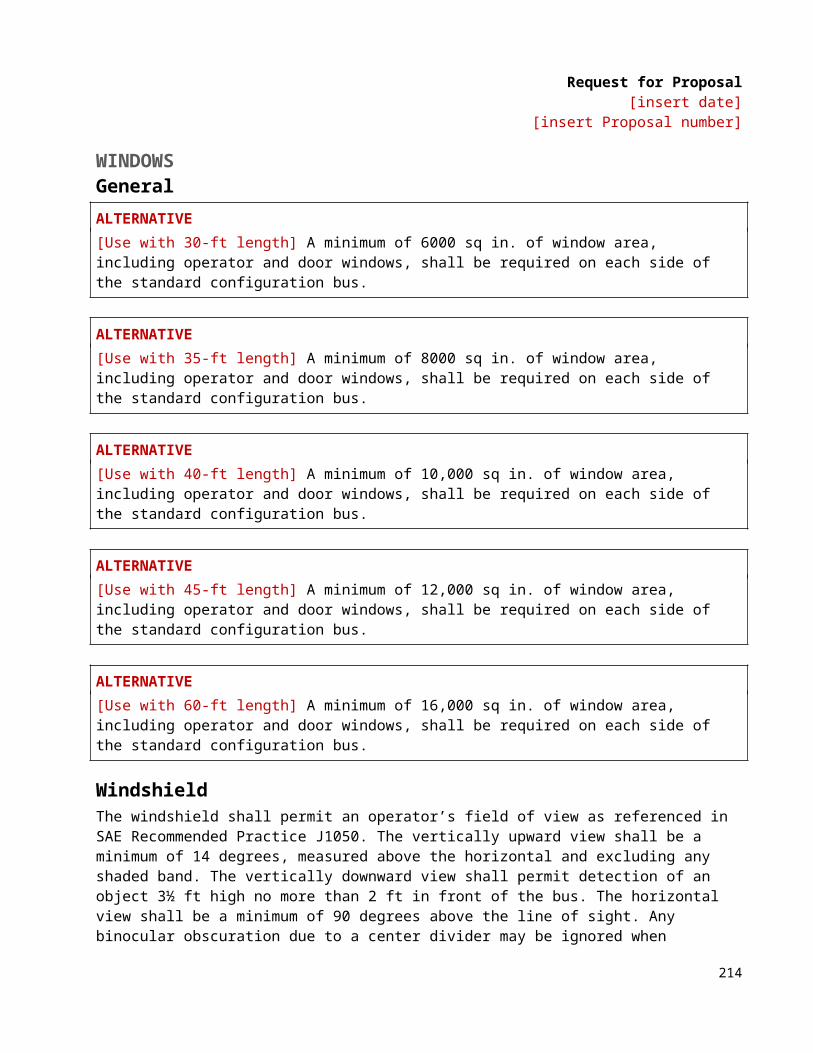
Request for Proposal[insert date]
[insert Proposal number]
• Interior inspection (including functionality)• Hoist/undercarriage inspection• Exterior inspection (including roof)• Electrical inspection• Wheelchair ramp/lift inspection
Water test inspectionThe water test inspection checks the integrity of the vehicle’s body seams, window frame seals and other exterior component close-outs for their ability to keep rainwater, road splash, melting snow and slush, and other exterior water from entering the inside of the vehicle. The vehicle’s interior is inspected for signs of moisture and water leaks. To perform the leak inspection, interior ceiling and side panels are removed, and access doors are opened. If any moisture or water is detected, then the source of the leak will be located and repaired by the manufacturer, and the vehicle will be tested again.
Road test inspectionThe road test inspection checks all the vehicle’s systems and sub-systems while the vehicle is in operation. Typically, the road test inspection is performed immediately following the water test inspection to reveal any standing water that may be present due to a leak, but was not noticed during the “static” water test. Objectionable vibrations, air leakage and other factors that affect ride quality are recorded and reported to the vehicle manufacturer for resolution. Vehicle stability, performance, braking and interlock systems, HVAC, and other critical areas are checked to ensure that the vehicle is complete and ready to provide safe and reliable service.
The following tests may be performed and recorded during the road test:
• Acceleration test• Top speed test• Gradability test• Service brake test• Parking brake test• Turning effort test• Turning radius test• Shift quality• Quality of retarder or regenerative braking action
During the road test, a vehicle may be taken to a weigh station to record the vehicle’s front axle weight, rear axle weight and total vehicle (curb) weight.
Interior inspectionThe interior inspection checks the fit and finish of the interior installations.
In addition, the inspection also verifies the installation and function of systems and subsystems according to the Build Specification. All systems and functions accessed from the interior are inspected for functionality, appearance and safety.
216
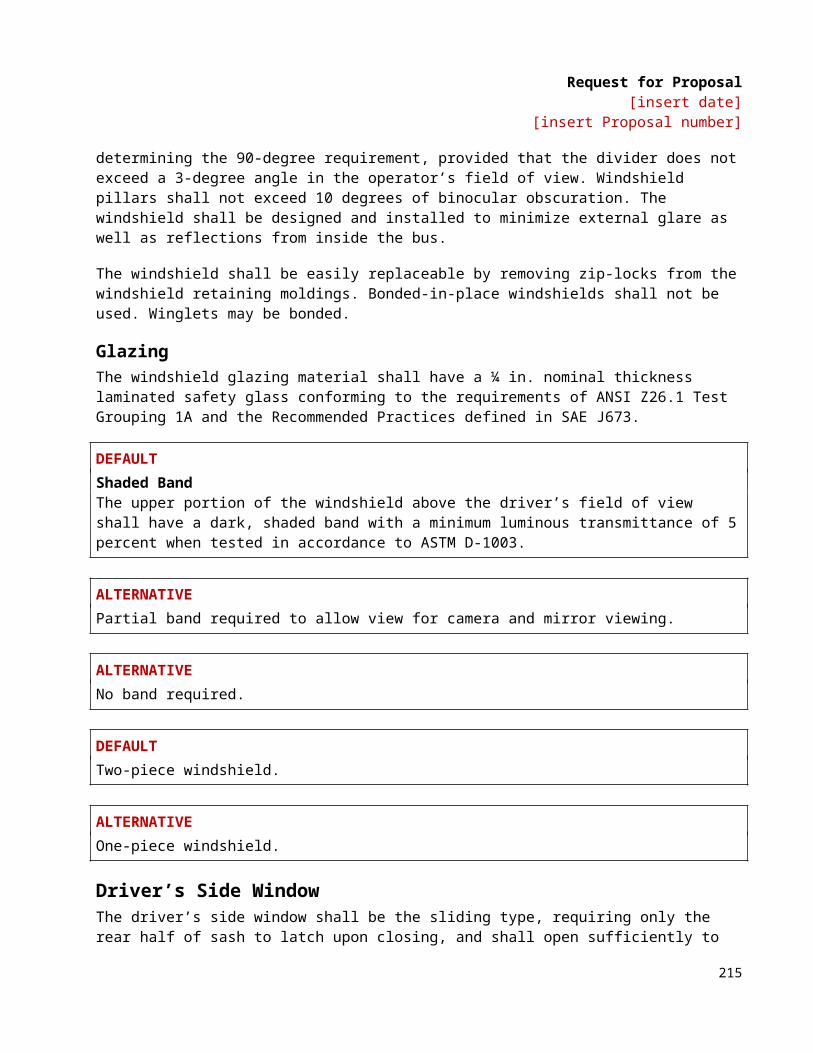
Request for Proposal[insert date]
[insert Proposal number]
Examples of systems/functions inspected include the following:
• Interior and exterior lighting controls• Front and rear door systems• Flooring installation• Passenger and operator’s seat systems• Wheelchair securement and ramp systems• Fire suppression system• Electrical installations (multiplex, tell-tale wiring, panels, etc.)• Window systems and emergency escape portals• Operator dash/side panel controls/indicators
Hoist/undercarriage inspectionThe hoist/undercarriage inspection checks the installation of components, wiring, air lines, presence of fluid leaks, etc., located under the vehicle. Typically, this inspection is performed following the road test. The vehicle is lifted onto a hoist or pulled over a pit for the inspection. Areas inspected are the front suspension, air bags, air line routings, electrical connections and routings, drive-train components, linkages, and any other system or component that may be prone to early failure due to inadequate installation techniques. All lines, cables, hoses, etc., are inspected for proper securement and protection to prevent rubbing, chafing or any other condition that could result in a failure. The engine/powerplant and HVAC compartments are also inspected during this time.
Exterior inspectionThe exterior inspection checks the fit and finish of components installed on the exterior of the vehicle. Access panels are opened and accessories are inspected for proper installation. In addition, vehicle paint, graphics and proper decals are also inspected. Acceptable paint finish quality (orange peel, adhesion, etc.) should be agreed on with the vehicle manufacturer prior to production to ensure consistency of inspections.
Electrical inspectionThe vehicle’s main electrical panels and other sub-panels are inspected for proper components, to include relays, fuses, modules, terminal strips, decals, etc. In addition, electrical harnesses are inspected for proper wiring and termination techniques, bulkhead protection, looming and other items that could result in future electrical failure. Onboard vehicle compartment schematics are verified for accuracy.
Wheelchair ramp inspectionThe wheelchair ramp assembly is inspected for proper installation and performance. Clearances critical to the operation of the ramp are verified, and the ramp’s electrical systems are inspected to ensure appropriate wire routings and protection. The successful integration of the ramp assembly into the vehicle is verified, and the vehicle interlocks are checked during automatic and manual ramp operation.
AuditsDuring serial production of the bus’s quality assurance inspection, tests may be performed to ensure that the manufacturer’s quality standards are being followed. These inspection audits could be on items such as torque wrench calibrations, proper techniques for fastener installations, proper use and type of adhesives, use of correct installation drawings on the production line, etc.
217
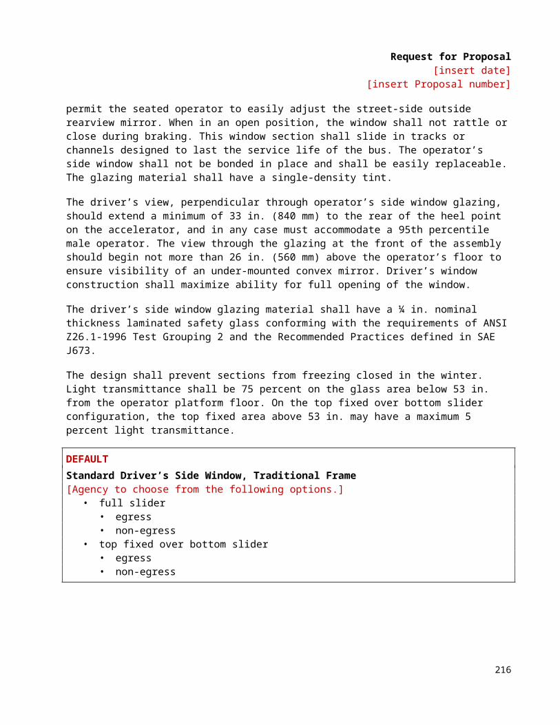
Request for Proposal[insert date]
[insert Proposal number]
CommunicationsThe lines of communications, formal and informal, should be discussed and outlined in the pre-production meeting. As previously discussed, resident inspectors should represent the agency for all bus-build related issues (quality, conformance, etc.). Resident inspectors can relay communications addressing contractual type issues but should do so only under the consult of the agency’s contracts administrator. Actual personnel contacts for the manufacturing facility should be established during resident inspector orientation. These contacts could include quality assurance, production, material handling, engineering, and buy-off area personnel.
DocumentationThe following documents/reports are typically generated during the bus build process:
• Vehicle Build Specification• Sales Order• Pre-production meeting notes• Prototype and production correspondence (vehicle build file)• Manufacturer’s Vehicle Record (Warranty file)
• Vehicle line documents• Serialization documents (Warranty file)• Alignment verification• Brake testing• HVAC testing and checkout• Manufacturer’s QA checklist and signoff
• Weight Slip (Prototype & Warranty file)• Prototype Performance Tests document (vehicle build file)
• Acceleration Test• Top Speed Test• Gradability Test• Interior Noise Test A – Stationary • Interior Noise Test B – Dynamic• Exterior Noise Test A – Pull Away• Exterior Noise Test B – Pass-By• Exterior Noise Test C – Curb Idle• Turning Radius Test• Turning Effort Test• Parking Brake Test• Service Brake Test
• Vehicle Acceptance Inspections – Production (Warranty file)• Water Test Inspection Report • Road Test Inspection Report• Interior Inspection Report • Hoist/Undercarriage Inspection Report • Exterior Inspection Report • Electrical Inspection Report• Wheelchair Inspection Report
• Speed Memos (Warranty file)• Agency Vehicle Inspection record (Warranty file)• Release for Delivery documentation (Warranty file)
218
Request for Proposal[insert date]
[insert Proposal number]
• Post-Production Acceptance – Certificate of Acceptance (Accounting)• Post-Delivery Inspection Report – (Fleet Management & Warranty files)
Vehicle release for deliveryUpon satisfactory completion of all inspection, audit and test criteria, and resolution of any outstanding issues affecting the purchase of any or all buses, proper documentation (the Release for Delivery) is signed by the designated resident inspector authorizing the bus manufacturer to deliver the vehicle to the agency’s facility, where it will undergo a post-delivery inspection process and final acceptance. The satisfactory sign-off of the Release for Delivery should complete the resident inspector’s duties for each bus. In final preparation for delivery, the bus manufacturer may request the resident inspector to do a final walk-through of the bus after it has been cleaned and prepped for shipping.
Post-delivery and final acceptanceThe agency shall conduct acceptance tests on each delivered bus. These tests shall be completed within 15 days after bus delivery and shall be conducted in accordance with the agency’s written test plans. The purpose of these tests is to identify defects that have become apparent between the time of bus release and delivery to the agency. The post-delivery tests shall include visual inspection, along with a verification of system(s) functionality and overall bus operations. No post-delivery test shall apply new criteria that are different from criteria applied in a pre-delivery test.
Buses that fail to pass the post-delivery tests are subject to non-acceptance. The agency shall record details of all defects on the appropriate test forms and shall notify the contractor of acceptance or non-acceptance of each bus within five days after completion of the tests. The defects detected during these tests shall be repaired according to procedures defined in the contract after non-acceptance.
Certificate of Acceptance• Accepted • Not accepted: In the event that the bus does not meet all requirements for acceptance. The agency
must identify reasons for non-acceptance and work with the OEM to develop a timeline of addressing the problem for a satisfactory resolution and redelivery.
• Conditional acceptance: In the event that the bus does not meet all requirements for acceptance, the agency may conditionally accept the bus and place it into revenue service pending receipt of contractor furnished materials and/or labor necessary to address the identified issue(s).
219
Request for Proposal[insert date]
[insert Proposal number]
SECTION 9: FORMS AND CERTIFICATIONS
CER 1. Proposer’s ChecklistRFP [insert name of procurement]Package 1: Technical Proposal
□ 1. Letter of Transmittal
□ 2. Technical Proposal
□ 3. Acknowledgement of Addenda
□ 4. Form for Proposal Deviation
□ 5. Vehicle Questionnaire
□ 6. References and non-priced information (if provided by Proposer)
□ 7. Engineering organization chart, engineering change control procedure, field modification process
□ 8. Manufacturing facility plant layout, other contracts, staffing
□ 9. Production schedule and other Contract commitments for the duration of this Contract.
□ 10. Quality Assurance Program
Package 2: Price Proposal
□ 1. Letter of Transmittal
□ 2. Pricing Schedule (including option buses, spare parts package, engineering, manuals, training, special tools and test equipment)
Package 3: Qualifications Package
□ 1. Pre-Award Evaluation Data Form
□ 2. A copy of the three (3) most recent audited financial statements or a statement from the Proposer regarding how financial information may be reviewed by the Agency
□ 3. Letter for insurance
□ 4. Letter for performance bond (if applicable)
□ 5. Letter of commitment for parental financial guarantee (if applicable)
□ 6. Proposal Form
Package 4: Proprietary/Confidential Information Package1
□ 1. Proprietary/Confidential Information
1. There may be items in the first three packages that are included in Package 4 because they are considered to be proprietary/confidential information. When this occurs, the Proposer must note that fact in Packages 1 through 3.
220

Request for Proposal[insert date]
[insert Proposal number]
CER 2. Request for Pre-Offer Change or Approved EqualThis form must be used for requested clarifications, changes, substitutes or approval of items equal to items specified with a brand name and must be submitted as far in advance of the Due Date, as specified in “Questions, Clarifications and Omissions.”
[Insert Agency name][Insert RFP number and title]
Request #: Proposer: RFP Section: Page:
Questions/clarification or approved equal: ]
Agency action:□ Approved□ See addendum
□ Denied□ See response below
Agency response:
221

Request for Proposal[insert date]
[insert Proposal number]
CER 3. Acknowledgement of AddendaFailure to acknowledge receipt of all addenda may cause the Proposal to be considered nonresponsive to the Solicitation. Acknowledged receipt of each addendum must be clearly established and included with the Proposal.
The undersigned acknowledges receipt of the following addenda to the documents:
Addendum No.: Dated:
Addendum No.: Dated:
Addendum No.: Dated:
Addendum No.: Dated:
Proposer: Name: Title: Phone: Street address: City, state, ZIP:
________________________________________________________________________ _______________________Authorized signature Date
222

Request for Proposal[insert date]
[insert Proposal number]
CER 4. Contractor Service and Parts Support Data
Location of nearest Technical Service Representative to AgencyName: Address:Telephone:Describe technical services readily available from said representative:
Location of nearest Parts Distribution Center to Agency:Name: Address:Telephone:Describe the extent of parts available at said center:
Policy for delivery of parts and components to be purchased for service and maintenance:Regular method of shipment: Cost to Agency:
223
Request for Proposal[insert date]
[insert Proposal number]
CER 5. Form for Proposal DeviationThis form shall be completed for each condition, exception, reservation or understanding (i.e., Deviation) in the Proposal according to “Conditions, Exceptions, Reservations or Understandings.” One copy without any price/cost information is to be placed in the Technical Proposal as specified in “Technical Proposal Requirements,” and a separate copy with any price/cost information placed in the Price Proposal as specified in “Price Proposal Requirements.”
[Insert Agency name][Insert RFP number and title]
Deviation No.: Contractor: RFP section: Page:
Complete description of Deviation:
Rationale (pros and cons):
224
Request for Proposal[insert date]
[insert Proposal number]
CER 6. Pricing ScheduleNOTE: The following is an example of what a pricing schedule might look like and should be customized by the Agency to reflect the costs for its procurement.
[Insert Agency name][Insert RFP number and title]
All prices are to be in United States dollars
Unit Price Extension
[Insert quantity, size, type and description] buses
Manuals Lump Sum
Training Lump Sum
Spare parts package
Test equipment and special tools
Extended Warranty [Agency to identify subsystem]
Extended Warranty [Agency to identify subsystem]
Extended Warranty [Agency to identify subsystem]
Extended Warranty [Agency to identify subsystem]
Other [Agency to specify]
Sales tax (if applicable)
Delivery charges
TOTAL PROPOSED PRICE
ADA equipment (included in above unit prices)
This form is to be completed and included in the Price Package.
225
Request for Proposal[insert date]
[insert Proposal number]
CER 7. Pre-Award Evaluation Data Form
NOTE: This form is to be completed and included in the Qualification Package. Attach additional pages if required.
[Insert Agency name][Insert RFP number and title]
1. Name of firm: 2. Address:
3. □ Individual □ Partnership □ Corporation □ Joint Venture4. Date organized:
State in which incorporated: 5. Names of officers or partners:
a. b. c. d. e.
6. How long has your firm been in business under its present name?
7. Attach as SCHEDULE ONE a list of similar current contracts that demonstrates your available capacity, including the quantity and type of bus, name of contracting party, percentage completed and expected completion date.
8. Attach as SCHEDULE TWO a list of at least three similar contracts that demonstrates your technical proficiency, each with the name of the contracting party and number and they type of buses completed within the last five years.
9. Have you been terminated or defaulted, in the past five years, on any Contract you were awarded? □ Yes □ NoIf yes, then attach as SCHEDULE THREE the full particulars regarding each occurrence.
10. Attach as SCHEDULE FOUR Proposer’s last three (3) financial statements prepared in accordance with generally accepted accounting principles of the jurisdiction in which the Proposer is located, and audited by an independent certified public accountant; or a statement from the Proposer regarding how financial information may be reviewed by the Agency [This may require execution of an acceptable non-disclosure agreement between the Agency and the Proposer.]
11. Attach as SCHEDULE FIVE a list of all principal Subcontractors and the percentage and character of Work (Contract amount) that each will perform on this Contract.
12. If the Contractor or Subcontractor is a joint venture, submit PRE-AWARD EVALUATION DATA forms for each member of the joint venture.
The above information is confidential and will not be divulged to any unauthorized personnel.
The undersigned certifies to the accuracy of all information:Name and title: Company:
________________________________________________________________________ _______________________Authorized signature Date
226
Request for Proposal[insert date]
[insert Proposal number]
CER 8. Federal CertificationsCER 8.1 Buy America CertificationThis form is to be submitted with an offer exceeding the small purchase threshold for federal assistance programs, currently set at $100,000.
Certificate of ComplianceThe Proposer hereby certifies that it will comply with the requirements of 49 USC Section 5323(j)(2)(C), Section 165(b)(3) of the Surface Transportation Assistance Act of 1982, as amended, and the regulations of 49 CFR 661.11:
Name and title: Company:
________________________________________________________________________ _______________________Authorized signature Date
Certificate of Non-ComplianceThe Proposer hereby certifies that it cannot comply with the requirements of 49 USC Section 5323(j)(2)(C) and Section 165(b)(3) of the Surface Transportation Assistance Act of 1982, as amended, but may qualify for an exception to the requirements consistent with 49 USC Sections 5323(j)(2)(B) or (j)(2)(D), Sections 165(b)(2) or (b)(4) of the Surface Transportation Assistance Act, as amended, and regulations in 49 CFR 661.7.
Name and title: Company:
________________________________________________________________________ _______________________Authorized signature Date
227
Request for Proposal[insert date]
[insert Proposal number]
CER 8.2 Debarment and Suspension Certification for Prospective ContractorPrimary covered transactions must be completed by proposer for contract value over $25,000.
Choose one alternative:
□ The Proposer, [insert name], certifies to the best of its knowledge and belief that it and its principals:
1. Are not presently debarred, suspended, proposed for debarment, declared ineligible, or voluntarily excluded from covered transactions by any federal department or agency;
2. Have not within a three-year period preceding this Proposal been convicted of or had a civil judgment rendered against them for commission of fraud or a criminal offense in connection with obtaining, attempting to obtain, or performing a public (federal, state or local) transaction or Contract under a public transaction; violation of federal or state antitrust statutes or commission or embezzlement, theft, forgery, bribery, falsification or destruction of records, making false statements, or receiving stolen property;
3. Are not presently indicted for or otherwise criminally or civilly charged by a governmental entity (federal, state, or local) with commission of any of the offenses enumerated in Paragraph 2 of this certification; and
4. Have not within a three-year period preceding this Proposal had one or more public transactions (federal, state or local) terminated for cause or default.
OR
□ The Proposer is unable to certify to all of the statements in this certification, and attaches its explanation to this certification. (In explanation, certify to those statements that can be certified to and explain those that cannot.)
The Proposer certifies or affirms the truthfulness and accuracy of the contents of the statements submitted on or with this certification and understands that the provisions of Title 31 USC § Sections 3801 are applicable thereto.
Executed in [insert city and state].Name:
________________________________________________________________________ _______________________Authorized signature Date
228
Request for Proposal[insert date]
[insert Proposal number]
CER 8.3 Debarment and Suspension Certification (Lower-Tier Covered Transaction)This form is to be submitted by each Subcontractor receiving an amount exceeding $25,000.
The prospective lower-tier participant (Proposer) certifies, by submission of this Proposal, that neither it nor its “principals” as defined at 49 CFR § 29.105(p) is presently debarred, suspended, proposed for debarment, declared ineligible, or voluntarily excluded from participation in this transaction by any Federal department or Agency.
If the prospective Proposer is unable to certify to the statement above, it shall attach an explanation, and indicate that it has done so by placing an “X” in the following space: ______
THE PROPOSER, ________________________________________________, CERTIFIES OR AFFIRMS THE TRUTHFULNESS AND ACCURACY OF EACH STATEMENT OF ITS CERTIFICATION AND EXPLANATION, IF ANY. IN ADDITION, THE PROPOSER UNDERSTANDS AND AGREES THAT THE PROVISIONS OF 31 USC §§ 3801 ET SEQ. APPLY TO THIS CERTIFICATION AND EXPLANATION, IF ANY.
Name and title of the proposer’s authorized official:
________________________________________________________________________ _______________________Authorized signature Date
229

Request for Proposal[insert date]
[insert Proposal number]
CER 8.4 Non-Collusion AffidavitThis affidavit is to be filled out and executed by the Proposer; if a corporation makes the bid, then by its properly executed agent. The name of the individual swearing to the affidavit should appear on the line marked “Name of Affiant.” The affiant’s capacity, when a partner or officer of a corporation, should be inserted on the line marked “Capacity.” The representative of the Proposer should sign his or her individual name at the end, not a partnership or corporation name, and swear to this affidavit before a notary public, who must attach his or her seal.
State of ____________________________________, County of _____________________________________________
I, _______________________________________________________, being first duly sworn, do hereby state that (Name of Affiant)
I am _______________________________________ of ______________________________________________________ (Capacity) (Name of Firm, Partnership or Corporation)
whose business is ___________________________________________________________________________________
and who resides at ___________________________________________________________________________________
and that _____________________________________________________________________________________________ (Give names of all persons, firms, or corporations interested in the bid)
is/are the only person(s) with me in the profits of the herein contained Contract; that the Contract is made without any connection or interest in the profits thereof with any persons making any bid or Proposal for said Work; that the said Contract is on my part, in all respects, fair and without collusion or fraud, and also that no members of the Board of Trustees, head of any department or bureau, or employee therein, or any employee of the Authority, is directly or indirectly interested therein.
______________________________________________________________________ ___________________________Signature of Affiant Date
Sworn to before me this ____________ day of __________________________, 20_____.
_______________________________________________ __________________________Notary public My commission expires Seal
230
Request for Proposal[insert date]
[insert Proposal number]
CER 8.5 Lobbying CertificationThis form is to be submitted with an offer exceeding $100,000.
The Proposer certifies, to the best its knowledge and belief, that:
1. No federal appropriated funds have been paid or will be paid, by or on behalf of the undersigned, to any person for influencing or attempting to influence an officer or employee of a federal department or agency, a member of the U.S. Congress, an officer or employee of the U.S. Congress, or an employee of a member of the U.S. Congress in connection with the awarding of any federal Contract, the making of any federal grant, the making of any federal loan, the entering into of any cooperative agreement, and the extension, continuation, renewal, amendment or modification thereof.
2. If any funds other than federal appropriated funds have been paid or will be paid to any person for making lobbying contacts to an officer or employee of any agency, a member of Congress, an officer or employee of Congress, or an employee of a member of Congress in connection with this federal Contract, grant, loan or cooperative agreement, the undersigned shall complete and submit Standard Form LLL, “Disclosure Form to Report Lobbying,” in accordance with its instruction, as amended by “Government-wide Guidance for New Restrictions on Lobbying,” 61 Fed. Reg. 1413 (1/19/96).
3. The undersigned shall require that the language of this certification be included in the award documents for all subawards at all tiers (including subcontracts, subgrants and contracts under grants, loans and cooperative agreements) and that all subrecipients shall certify and disclose accordingly. This certification is a material representation of fact upon which reliance was placed when this transaction was made or entered into. Submission of this certification is a prerequisite for making or entering into this transaction imposed by 31, USC § 1352 (as amended by the Lobbying Disclosure Act of 1995). Any person who fails to file the required certification shall be subject to a civil penalty of not less than $10,000 and not more than $100,000 for each such failure.
THE PROPOSER, _____________________________________________, CERTIFIES OR AFFIRMS THE TRUTHFULNESS AND ACCURACY OF EACH STATEMENT OF ITS CERTIFICATION AND DISCLOSURE, IF ANY. IN ADDITION, THE PROPOSER UNDERSTANDS AND AGREES THAT THE PROVISIONS OF 31 USC §§ 3801 ET SEQ. APPLY TO THIS CERTIFICATION AND DISCLOSURE, IF ANY.
Name of the bidder or Proposer’s authorized official: __________________________________________________
Title: _________________________________________________________________________________________________
________________________________________________________________________ ________________________Signature Date
Per paragraph 2 of the included form Lobbying Certification, add Standard Form–LLL, “Disclosure Form to Report Lobbying,” if applicable.
231

Request for Proposal[insert date]
[insert Proposal number]
CER 8.6 Certificate of Compliance with Bus Testing RequirementThe undersigned certifies that the vehicle offered in this procurement complies and will, when delivered, comply with 49 USC § 5323(c) and FTA’s implementing regulation at 49 CFR Part 665 according to the indicated one of the following three alternatives.
Mark one and only one of the three blank spaces with an “X.”
1. _____ The buses offered herewith have been tested in accordance with 49 CFR Part 665 on _____________ (date). If multiple buses are being proposed, provide additional bus testing information below or on attached sheet. The vehicles being sold should have the identical configuration and major components as the vehicle in the test report, which must be submitted with this Proposal. If the configuration or components are not identical, then the manufacturer shall provide with its Proposal a description of the change and the manufacturer’s basis for concluding that it is not a major change requiring additional testing. If multiple buses are being proposed, testing data on additional buses shall be listed on the bottom of this page.
2. _____ The manufacturer represents that the vehicle is “grandfathered” (has been used in mass transit service in the United States before October 1, 1988, and is currently being produced without a major change in configuration or components), and submits with this Proposal the name and address of the recipient of such a vehicle and the details of that vehicle’s configuration and major components.
3. _____ The vehicle is a new model and will be tested and the results will be submitted to the Agency prior to acceptance of the first bus.
The undersigned understands that misrepresenting the testing status of a vehicle acquired with federal financial assistance may subject the undersigned to civil penalties as outlined in the Department of Transportation’s regulation on Program Fraud Civil Remedies, 49 CFR Part 31. In addition, the undersigned understands that FTA may suspend or debar a manufacturer under the procedures in 49 CFR Part 29.
Company name: Name and title of the proposer’s authorized official:
________________________________________________________________________ _______________________Authorized signature Date
232

Request for Proposal[insert date]
[insert Proposal number]
CER 8.7 DBE Approval CertificationI hereby certify that the Proposer has complied with the requirements of 49 CFR 26, Participation by Disadvantaged Business Enterprises in DOT Programs, and that its goals have not been disapproved by the Federal Transit Administration.
Name and title of the proposer’s authorized official:
________________________________________________________________________ _______________________Authorized signature Date
233

Request for Proposal[insert date]
[insert Proposal number]
CER 8.8 Federal Motor Vehicle Safety StandardsThe Proposer and (if selected) Contractor shall submit (1) manufacturer’s FMVSS self-certification sticker information that the vehicle complies with relevant FMVSS or (2) manufacturer’s certified statement that the contracted buses will not be subject to FMVSS regulations.
Company name: Name of signer: Title:
________________________________________________________________________ _______________________Authorized signature Date
234
Request for Proposal[insert date]
[insert Proposal number]
CER 9. Other CertificationsCER 9.1 Proposal Form
NOTE: The following is an example of a Proposal form to be modified as appropriate by the Agency and included in the RFP.
Proposer shall complete the following form and include it in the price Proposal.
PROPOSALBy execution below by a duly authorized representative(s) of the Proposer, the Proposer hereby offers to furnish equipment and services as specified in its Proposal submitted to [insert Agency name] in response to Request for Proposal No. [insert RFP number] in its entirety.
Proposer: ______________________________________________________________________________________________
Street address: _________________________________________________________________________________________
City, state, ZIP: _________________________________________________________________________________________
Name and title of Authorized Signer(s): __________________________________________________________________
Name and title of Authorized Signer(s): __________________________________________________________________
Phone: _________________________________________________________________________________________________
______________________________________________________________________________ _____________________Authorized signature Date
______________________________________________________________________________ _____________________Authorized signature Date
235
Request for Proposal[insert date]
[insert Proposal number]
CER 9.2 Notice of Award
NOTE: This form is included as an example. Standard industry practice is to execute a separate Contract as provided as an example in Appendix E.
By execution below, [insert Agency name] accepts Proposal as indicated above.
Contracting officer: _________________________________________________________________________________
________________________________________________________________________ _______________________Authorized signature Date
236
Request for Proposal[insert date]
[insert Proposal number]
CER 10. Vehicle Questionnaire NOTE: This is a sample form. The Agency should customize to comply with its proposed requirements.
This form must be completed and included in the Technical Proposal.
GENERAL COACH DATA SHEET:
[INSERT BUS TYPE]Bus Manufacturer: __________________________________________________________________________________
Bus Model Number: ________________________________________________________________________________
Basic Body Construction Type: ____________________________________________________________________
General DimensionsOverall length Over bumpers feet inches
Over body feet inches
Overall width Over body excluding mirrors and lights feet inches
Over body including mirrors feet inches
Over tires feet inches
Overall height (maximum) feet inches
Angle of approach degrees
Angle of departure degrees
Breakover angle 1 degrees
Breakover angle 2 degrees
Doorway clear opening (at widest point) inches
Width with grab handles Width without grab handles HeightFront door inches inches inches
Center door (1) inches inches inches
Center door (2) inches inches inches
Rear door inches inches inches
Front axle floor height above ground (centerline of bus) inches
Center axle floor height above ground (centerline of bus) inches
Rear axle floor height above ground (centerline of bus) inches
Step height from ground (measured at center of doorway) inches
237

Request for Proposal[insert date]
[insert Proposal number]
Front doorway Center doorway Ramp angle Rear doorway
Kneeled inches (a) inches (a) degrees (R1) inches (a)
Unkneeled inches (b) inches (b) degrees (R2) inches (b)
Interior head room (floor to ceiling at center of aisle)First axle location inches
Center of articulation inches
Rear axle location inches
Rear settee (in front of seat) inches
Aisle widthMinimum width on floor between first axle wheel housings inches
Minimum width on floor between center axle (1) wheel housings inches
Minimum width on floor between center axle (2) wheel housings inches
Minimum width on floor between rear axle wheel housings inches
Minimum ground clearanceOutside axles zones inches
Inside axles zones inches
238
Request for Proposal[insert date]
[insert Proposal number]
Horizontal turning envelope (see diagram below)
Outside body turning radius, TR0 (including bumper) feet inches
Inside Body Turning Radius innermost point, TR4 (including bumper) feet inches
Wheel baseFirst axle to center/rear axle inches
Center axle to rear axle inches
Overhang, centerline of axle over bumperFront inches
Rear inches
FloorMaximum interior floor slope (from horizontal) degrees
CapacityTotal number of passenger sittings
Passenger seating manufacturer/model number
Total number of standing passengers (1 per 1.5 sq. ft.)
Minimum hip to knee space inches
Maximum hip to knee space inches
Restraint system type and model number
Bus weightCurb weight Curb weight plus seated load* GVWR
First axle lbs lbs lbs
Center axle lbs lbs lbs
Rear axle lbs lbs lbs
Total lbs lbs lbs
* Including operator and passengers at 150 lbs per person
239
Request for Proposal[insert date]
[insert Proposal number]
Steering AxlesManufacturer
Type and weight rating
Model number
240
Request for Proposal[insert date]
[insert Proposal number]
Drive axle (□ Center □ Rear)
Manufacturer
Type and weight rating
Model number
Drive axle ratioDifferential ratio
Hub reduction ratio (if used)
Final axle ratio (if hub reduction is used)
Brake systemMake/type of fundamental system
First axle brake chamber model
Center axle brake chamber model
Rear axle brake chamber model
First axle slack adjuster
Manufacturer
Model number
Center axle slack adjuster
Manufacturer
Model number
Rear axle slack adjuster
Manufacturer
Model number
First axle brake drum/rotor
Manufacturer
Center axle brake drum/rotor
Manufacturer
Rear axle brake drum/rotor
Manufacturer
Air compressorManufacturer
Type
Model number
Rated capacity cfm
Capacity at idle cfm
Maximum warranted speed rpm
241
Request for Proposal[insert date]
[insert Proposal number]
Idle speed rmp
Drive type
Governor cut-in pressure psi
Governor cut-out pressure psi
Air Reservoir CapacityManufacturer
Supply reservoir number and size / cubic inches total
Primary reservoir number and size / cubic inches total
Secondary reservoir number and size / cubic inches total
Parking reservoir number and size / cubic inches total
Accessory reservoir number and size / cubic inches total
Other reservoir number and size / cubic inches total
Cooling SystemRadiator Charge air cooler
Manufacturer
Type
Model number
Number of tubes
Fins per inch
Fin thickness (inches)
Fin construction
Total cooling system capacity (gallons) gallons
Radiator fan manufacturer
Fan speed/control type (mech/elect/hyb)
Surge tank capacity gallons
Surge tank material
Overheat alarm temperature degrees F
Shutdown temperature settings degrees F
242
Request for Proposal[insert date]
[insert Proposal number]
ElectricalPrimary interior lighting systemManufacturer
Type
Model number
AlternatorManufacturer
Type
Model number
Output at idle amps
Voltage regulatorManufacturer
Model number
Voltage equalizerManufacturer
Model number
Auxiliary inverter (120/240)Manufacturer
Model number
Inverter technology
Output voltage(s)
Starter motorManufacturer
Voltage
Model number
Energy storageBatteries – low voltage
Manufacturer
Type
Model number
Cold cranking amps
Batteries/energy storage – high voltage
Manufacturer
243
Request for Proposal[insert date]
[insert Proposal number]
Type
Model number
Energy density
Specific power
Operating temperature range
Cooling/heating system
Ultra-capacitor
Manufacturer
Model number
Ultra-capacitor ratings: Provide data sheet for energy efficiency, estimated calendar life, cycle life, voltage (each capacitor and each module), working and peak power, and weight
EngineManufacturer
Model number/version
Horsepower/torque rating
Fire Suppression/Methane Detection SystemManufacturer
Model number
Number of detectors fire methane
Type of detector □ Thermal □ Optical
Battery backup □ Yes □ No
BumpersManufacturer
Type
Fuel and Exhaust SystemFuel type
Operating range and route profile
Fuel tanks (liquid fuels)Manufacturer
Capacity (total and usable) Gallons / Gallons
Construction material
Quantity and location of tanks
Fuel tanks (gaseous fuels)
244
Request for Proposal[insert date]
[insert Proposal number]
Manufacturer
Capacity (total and usable) SCF / SCF
Construction material
Quantity and location of tanks
Exhaust systemDiesel particulate filter manufacturer
Describe DPF electronic interface
Muffler manufacturer (if applicable)
Air SuspensionFront Middle Rear
Air spring manufacturer
Air spring quantity per axle
Shock absorber manufacturer
Shock absorber quantity per axle
SteeringPump manufacturer
Pump model number
Steering gear manufacturer
Steering gear model number
Steering gear type
Steering wheel diameter inches
Maximum effort at steering wheel** Unloaded stationary coach on dry asphalt pavement
245
Request for Proposal[insert date]
[insert Proposal number]
ArticulationArticulation joint manufacturer
Articulation joint model number
Bellows manufacturer
Bellows model number
□ Transmission / □ Hybrid drive system (check one)
Manufacturer
Type
Model number
Number of forward speeds
Traction motor horsepower rating
Type ventilation/cooling
PropshaftManufacturer
WheelsManufacturer
Type
Size
Mounting type
Bolt circle diameter
Protective coating
TiresManufacturer
Type
Size
Load range/air pressure
Door SystemDoor panels Manufacturer TypeFront door
Center door (1)
Center door (2)
Rear door
246

Request for Proposal[insert date]
[insert Proposal number]
Actuating mechanism (air, electric, spring, other)Manufacturer
Front door
Center door (1)
Center door (2)
Rear door
Heating and Ventilating EquipmentHeating system capacity Btu
Air conditioning system capacity Btu
Ventilating capacity CFM per passenger
Manufacturer and model
Refrigerant type
Driving heaterManufacturer
Type
Model number
Capacity
Auxiliary heaterManufacturer
Type
Model number
Capacity
Floor heatersManufacturer
Type/number
Model number
Capacity
247
Request for Proposal[insert date]
[insert Proposal number]
Passenger Loading SystemManufacturer
Type (hydraulic, electric or both)
Model number
Capacity (lbs.)
DimensionsWidth of ramp inches
Length of ramp inches
Cycle times Normal idle Fast idleStowed to ground seconds seconds
Ground to stow seconds seconds
ElectronicsVideo system manufacturer
Video system model number
Number of cameras
Multiplex system manufacturer
Multiplex system model number
Automatic passenger counter system manufacturer
Automatic passenger counter system model number
Destination sign manufacturer
Destination sign model number
AVL/AVM system manufacturer
AVL/AVM system model number
Passenger information system manufacturer
Passenger information system model number
Signal prioritization system manufacturer
Signal prioritization system model number
248

Request for Proposal[insert date]
[insert Proposal number]
Coach Body FittingsPassenger windows manufacturer
Exterior/interior mirrorsSize
Manufacturer
Model number
Manufacturer part numbers
Bicycle racksManufacturer
Model number
Paint systemManufacturer
Type
Operator control layout diagram:
249

Request for Proposal[insert date]
[insert Proposal number]
SECTION 10: CONTRACT
[Agency to insert its Form of Contract. A sample Contract is provided in Appendix D.]
250
Request for Proposal[insert date]
[insert Proposal number]
SECTION 11: APPENDIXES
Appendix A: Guidelines for Calculating Liquidated Damages Calculation of Liquidated Damages Prior to its Solicitation, the Agency should document and file for the record its derivation of the amount of liquidated damage that is entered in “Liquidated Damages for Late Delivery of the Bus.” The following identifies some suggested areas for consideration by which a Agency may be damaged if buses are not delivered as contracted.
For determining amounts for liquidated damages, the following guidance is provided:
1. The liquidated damage amount must not be punitive but shall be based upon damages that the Agency would incur as a result of the delay.
2. The liquidated damage amount must be calculated on the basis of damages that the Agency would incur and be substantiated by experience data.
3. A definition of days and any exempted days for delay should be included.
Cost to Retain Old FleetIf the purpose of the procurement is to replace older buses that are being retired, there can be two areas of damage that are additive: extra cost of maintenance and cost of purchasing or renting additional buses to meet fleet availability requirements.
1. Extra cost of maintenance. The difference in maintenance costs, old buses minus new ones, is a realistic damage, assuming that older buses will be continued in service for the duration and not replaced with alternative leased buses.
2. Cost to obtain additional buses to meet fleet availability. Reliability of the older buses is not expected to be as good as for new ones, and they can be expected to be out of service for maintenance or repair for longer periods than new ones. Therefore, additional buses may be needed to ensure that required service on routes is met.
Cost to Obtain Alternative FleetThe damage may be attributed to requirements to obtain an alternative fleet for the duration of the delay. Such may be precipitated because a sales agreement on the old buses being replaced is expected to have been executed prior to the Contract delivery date for new buses or because the new buses are needed for new or expanded services.
1. Cost to replace old buses being sold. This approach is an alternative to the cost of retaining the old fleet of (1) above. It is suggested that the liquidated damage be the lower of this alternative and that of (1).
2. Cost to meet requirements for new or expanded service. Under this approach, the liquidated damage would simply be the daily costs of the alternative fleet as calculated above.
Increased Contract Administrative CostsDelays in delivery will increase the period that the Contract must be administered and possibly increase the effort or waste the effort of either in-house staff or consultants for in-plant inspection and to assist in taking delivery and acceptance.
251

Request for Proposal[insert date]
[insert Proposal number]
1. Increased Contract period. The amount of the damage can be calculated as the average daily cost of Contract administration, apart from any technical services.
2. Increased technical services. Technical services for in-plant inspection and to assist in taking delivery and acceptance will have been budgeted consistent with the Contract schedule. The extra budget for these services could be determined as a daily rate.
FinesDamages may include fines for which a court has already imposed or can be expected to be imposed on the Procuring Authority not meeting required emission (noise or air quality) reductions or features mandated by the Americans with Disabilities Act. Include this element only if the Agency can prove its vulnerability for such fines and a purpose of the procurement is to comply with such laws or ordinances.
Fuel ConsumptionIf the new buses are expected to consume less fuel per passenger capacity, then the difference in fuel consumption costs per day may be included.
252
Request for Proposal[insert date]
[insert Proposal number]
Appendix B: Guidelines for Calculating Early Delivery Incentives Any provision of incentive payments for early delivery should be made on the basis of savings that may be reasonably expected to accrue to the Agency. Prior to its Solicitation, the Agency should document and file for the record its derivation of the amount of any incentive that would be entered in the option provided in “Liquidated Damages for Late Delivery of the Bus.” It is suggested that any savings be shared between the Contractor and the Agency on the basis of some predetermined ratio, not exceeding an amount approximately that of the anticipated profit under the Contract. The following provides suggested areas in which an Agency may accrue savings for early delivery.
Savings to Retire Old Fleet EarlyIf the purpose of the procurement is to replace older buses that are being retired, there can be savings in maintenance costs. The difference in maintenance costs, old buses minus new ones, could be a savings if the old fleet can be retired early.
Decreased Contract Administrative CostsEarly delivery can decrease the period that the Contract must be administered. The amount of savings can be calculated as the average daily cost of Contract administration, apart for any technical services.
FinesIf the Agency is being fined or can be expected to be imposed for failure to meet court-mandated emissions standards or requirements of the Americans with Disabilities Act, and early delivery reduces any such fines, savings will accrue. This element should be included only if the Agency can prove its vulnerability to such fines and a purpose of the procurement is to comply with such laws or ordinances.
Fuel Consumption If the new buses are expected to consume less fuel per passenger capacity, then the difference in fuel consumption costs per day may be included as a savings if the old fleet can in fact be replaced by the early delivered fleet.
253
Request for Proposal[insert date]
[insert Proposal number]
Appendix C: Examples of Evaluation Criteria
EXAMPLE 1: EVALUATION OF PROPOSALS AND SELECTION PROCESS A. Evaluation/Selection CommitteeAn Evaluation/Selection Committee (Committee), which may include Agency staff, consortium members, and possibly one or more outside experts, will review and screen the Proposals submitted according to the pre-established criteria as set forth below.
B. Pre-Proposal Meeting (maximum of 5 points)Attendance at the Pre-Proposal Meeting on [insert date].
C. Technical Evaluation Criteria (maximum of 80 points)Proposals will be evaluated using the following principal selection criteria:
1. Product design and performance (0-30 points): The information provided by the Proposer in its technical submittal relating to the buses to be provided will be utilized to evaluate the Proposal in relation to this factor. Vehicle construction and system design, as well as documented reliability, may be used in this evaluation, as well as other design and performance elements of the components that comprise those systems. At a minimum, test results, safety and maintenance factors, and cost of normal operation for the bus design and system components proposed, may be considered in determining a final value for this factor.
2. Proposer’s reputation and performance (0-30 points): The Committee will consider the capability and reputation of the Proposer as presented in the Proposal or as is determined by review of information available from references or other resources. The evaluation may look at the Proposer’s overall organizational and financial capabilities and consider key components such as organizational reporting structure, quality control, quality assurance, research and development, technical, training and parts support, response time, product capabilities, ability to furnish multiple bus configurations, bonding capacity, and financial history, as well as other considerations, in reaching a final point determination. The committee may also look at judgments, liens, Fleet Defect history, warranty claims and the steps that the manufacturer took to resolve these concerns in assessing the overall reputation of the manufacturer.
3. Delivery schedule (0-20 points): The Committee will review the proposed delivery schedule for the Agency’s minimum purchase of coaches. Delivery schedules that fulfill the delivery requirements, with evidence that the schedule can be accomplished, may receive higher points for this category.
D. Cost Proposal Evaluation (maximum of 20 points)As described below, the proposed cost as submitted by the Proposer on the Agency’s form will be assigned a maximum of 20 points. The Contractor is required to use the Agency’s form, without alteration, for submittal of its cost Proposal. Please DO NOT use your own forms.
The cost will be evaluated in the following manner:
1. Cost Proposal Criteria (0-20 points)
a. The Cost Proposal criteria will be based on the “Total of Both the Low-Floor and Standard Floor Bus,” Line 3.C. of Appendix B as noted in Section 8.B.6, “Sum of Total Base Offer per Bus.”
b. The lowest average Cost Proposal will receive 20 points. Every other Proposal previously found to be in the Competitive Range will be given points proportionately in relation to the lowest price. This point total will be calculated by dividing the lowest price by the total price of the Proposal
254
Request for Proposal[insert date]
[insert Proposal number]
being evaluated and the result multiplied by the maximum weight for price (20 points) to arrive at a Cost Proposal score.
Example: Lowest Proposed Price / Proposer’s Proposed Price × 20 = Proposal Score
The application of the above formula will result in a uniform assignment of points relative to the criterion of price.
E. Evaluation MethodologyThe maximum number of points achievable in each of the aforementioned areas is as follows:
• Attendance at Pre-Proposal Meeting: 0-5 points• Product design and performance: 0-30 points• Manufacturer’s reputation and performance: 0-30 points• Delivery schedule: 0-20 points• Cost proposal: 0-20 points
TOTAL POSSIBLE POINTS: 105
EXAMPLE 2: EVALUATION PROCESS Following receipt of the Proposals, the Proposals will be evaluated for compliance with the following minimum requirements. Those Proposals that do not evidence compliance may not be considered beyond the preliminary review.
Minimum Requirements• The Proposer must be an existing vehicle manufacturer with an existing manufacturing facility.• The Proposal must be for a high-capacity vehicle with a nominal length not to exceed 45 feet.• The vehicle must be constructed from composite material.• The proposed vehicle must have the capability for either a CNG propulsion system or for a
gasoline/hybrid propulsion system.• The proposed vehicle must have a minimum of 44 seats.
Proposals found to be compliant with the minimum qualifications will then be evaluated to determine those Proposals that represent technically acceptable offers.
255

Request for Proposal[insert date]
[insert Proposal number]
Each Proposal will be rated according to the following ratings:
Rating Definition
Exceptional Exceeds evaluation standard in a way beneficial to Agency, and has no significant weaknesses. Innovative, comprehensive and complete in all details. Low-risk. Complies with all primary program objectives for the procurement.
Acceptable Meets evaluation standards, and any weaknesses are readily correctable. Limited risk. Complies with many of the primary program objectives for the procurement.
Marginal Fails to meet evaluation standard; however, any significant deficiencies are correctable. Lacks essential information to support Proposal. Moderate risk. Complies with only one or two of the program objectives for the procurement.
Unacceptable Fails to meet evaluation standard, and the deficiency is uncorrectable. Proposal would have to undergo a major revision to become acceptable. Demonstrated lack of understanding of Agency’s requirements or omissions of major areas. Unacceptable risk. Complies with none or one of the program objectives for the procurement.
Performance risk is the evaluation of each Proposer’s present and past work to assess confidence in the Proposer’s ability to perform against a proposed Contract. The following definitions are used when assessing performance risk:
Rating Definition
High Significant doubt exists, based on the Proposer’s performance record, that the Proposer can perform the proposed effort.
Moderate Some doubt exists, based on the Proposer’s performance record, that the Proposer can perform the proposed effort.
Low Little doubt exists, based on the Proposer’s performance record, that the Proposer can perform the proposed effort.
Not applicable No significant performance record is identifiable.
The Agency may require clarifications or oral interviews with Proposers. Discussions may also be held with Proposers to determine acceptability of proposed Deviations and/or to address deficiencies and weaknesses of the Proposal. See “Agency Rights” for additional information.
After completion of the evaluations, the Agency shall request pricing from those firms that have submitted technically acceptable Proposals. The firms will be given approximately one week to submit pricing. The received pricing will then be reviewed. The Agency does not anticipate negotiation of price offers. The award will be made to the Proposer that possesses the appropriate facility, as well as the managerial, financial and technical capabilities necessary to fulfill the requirements of the Contract, and whose Proposal conforms to Solicitation requirements and is judged by an integrated assessment of the evaluation criteria to be most advantageous to the Agency, when price and other factors are considered.
For the purposes of this procurement, all evaluation factors other than price, when combined, are significantly more important than the cost/price area in this acquisition. Therefore, the Agency may select other than the lowest-priced technically acceptable Proposal if it is determined that the additional technical merit offered is
256
Request for Proposal[insert date]
[insert Proposal number]
worth the additional cost in relation to other Proposals received. For evaluation purposes, if Proposals become more technically equivalent, then price becomes relatively more important.
The Agency is more concerned with obtaining superior technical features than with making an award at the lowest overall price to the Agency. However, the Agency will not make an award at a significantly higher overall cost to the Agency to achieve slightly superior technical features.
The Agency reserves the right to reject any or all Proposals, to waive informalities or irregularities to the extent permitted by law in any Proposal received, and to be the sole judge of the merits of the respective Proposal received.
Evaluation Criteria The award will be based upon the factors listed below in addition to price and may not necessarily be made to the lowest-price Proposer. Factors are ranked in order of importance, with the most important factor listed first.
• Minimum vehicle performance requirements• Vehicle structure• Advanced design provisions • Proposed technical Deviations• Manufacturing process• Qualifications of the proposer• Past performance and current commitments• Maintainability• Proposed operating cost and reliability• Emissions• System safety provisions• Technical support• Project management• Deviations from Contract terms and conditions
The primary sub-criteria under each factor are the following:
• Performance requirements: • Vehicle performance• Reduced Exterior sound levels• Minimum range requirements• Compliance with General Performance requirements
• Vehicle structure:• Previous service experience of the vehicle, if applicable• Current and/or planned durability testing, including existing test results• Physical dimensions• Interior layout, including compliance with ADA requirements• Layout of the operator’s compartment, including the operator’s field of view• Available ergonomic information• Functional enhancements, including integration of electronic controls and minimizing the
number of gauges and switches• Advanced design provisions: This addresses the design characteristics, including how the design
complies with the program’s design objectives.
257
Request for Proposal[insert date]
[insert Proposal number]
• Proposed technical deviations: This addresses the effect and acceptability of proposed technical deviations, including proposed benefits to the Agency and Deviations that will result in cost reductions.
• Manufacturing process: This addresses the proposed manufacturing process, including a detailed description of the proposed facilities where the Work would be done.
• Proposed quality assurance program• Qualifications of the Proposer:
• Organization chart showing the organization proposed for this Contract• History of the Proposer, including information about manufacturing capabilities• Experience in producing the same or similar vehicles as those being proposed, with emphasis
on experience in producing CNG and gasoline/hybrid vehicles• Experience in producing composite structure vehicles• Maintenance and warranty experience, including a qualified staff to provide the necessary
services• Proposer’s ISO certification(s) or equivalent
• Proposer’s facilities to be used for significant portions of the Work, including Subcontractors’ facilities: • Location of the facility and whether the facility is owned or leased• Work to be performed at the facility• Capacity and resources available at the facility for fulfilment of this Contract• Length of time the facility has been in operation to do the kind of Work proposed to be
performed at the facility.• Past performance and current commitments:
• Reference list• Proposer’s Work under way, or for which the Proposer is committed
• Maintainability:• Maintainability of the proposed powerplant• Maintainability of proposed component parts• Maintenance requirements• Skills needed to perform maintenance Work• Required special equipment, tools or maintenance facility requirements that must be
implemented to maintain the vehicles• Proposed diagnostic equipment needed to maintain the vehicles • Proposed “built-in” diagnostic equipment, if offered• Reasonableness of proposed scheduled maintenance requirements• Proposed spare parts package required to support the schedule maintenance and replacement
of major components• Proposed operating costs and reliability:
• Expected reliability and service life of major proposed components• Projected emissions of the vehicle• System safety provisions:
• Proposed safety features• Knowledge of state codes and regulations affecting vehicles• Vehicle code changes required for the vehicle to legally operate in the state, if any
• Technical support:• Identification of proposed parts and service center• Service center staffing and qualifications• Availability of electronic maintenance documentation and comprehensive plan for providing
technical updates for the life of the proposed vehicles
258
Request for Proposal[insert date]
[insert Proposal number]
• Proposed availability of spare parts, including methodology for storing parts locally and for expediting needed parts
• Proposed training plans and instruction program• Proposed diagnostic equipment required to maintain the vehicles• Provision of advanced features such as wireless self-diagnostics and/or database
management.• Project management:
• Proposed general project schedule and plan to ensure schedule compliance or to expedite the delivery schedule
• Experience of the proposed project management team, including the experience of key personnel.
• Experience of technical personnel supporting each area of technical expertise as required by the Contract specifications, including test and system integration personnel
• Experience of the proposed key contact for the project, including the level of authority that this individual will have to make decisions that are “binding” on the Proposer
• Plan for the coordination of major Suppliers and Subcontractors, if any• Major component Suppliers and the products to be provided by each for this Contract• The interface relationships between engineering, manufacturing, program control, quality
control and test departments• Proposed critical path schedule for the production of the pilot vehicle and remaining vehicles
as well as the methodology for controlling the schedule• Proposed Deviations from nontechnical terms and conditions:
• Rationale for the proposed Deviation• Benefit and/or risk to Agency if the request is granted
Certifications The certifications will be reviewed for proper execution and responsiveness.
Type of Contract to be Awarded The Agency intends to award a fixed-price Contract per unit for up to [insert number] vehicles. The services of the Contractor will be based on the scope of Work as outlined in “Section 1” Description of Work.”
Period for Acceptance The Proposal shall be valid for [insert number] calendar days from the date stipulated in the RFP for receipt of Proposals. If this offer is accepted within that time period, the Proposer agrees to furnish all services and items as stipulated in the RFP and in any accompanying amendments.
259
Request for Proposal[insert date]
[insert Proposal number]
Appendix D: Sample Contract
NOTE: The following is a sample Contract which is included as an illustration of a format that an Agency may choose to use.
CONTRACT1. Contract Documents and Order of PrecedenceThe Contract consists of the documents listed below. In case of any conflict among these documents, the order of precedence shall be:
1. Form of Contract2. “Section 4: Special Provisions”3. “Section 3: General Conditions,” and “Section 5: Federal Requirements”4. “Section 6: Technical Specifications,” “Section 7: Warranty Requirements,” and
“Section 8: Quality Assurance”5. Contractor’s Best and Final Offer (including Contractor Proposal)
NOTE: An Agency may issue a conformed Contract that comprises all of the changes, Deviations and addenda that were a part of the negotiation process. In that case, the above order of precedence would be applicable. Absent a conformed Contract, it may be appropriate to include the Contractor’s final Proposal and BAFO as accepted by the Agency as the first document in the order of precedence. It should be noted that this alternative could present more risk to the Agency as the Contractor’s BAFO and Proposal could contradict the RFP requirements and would prevail over them.
In this instance, the order of precedence might be as follows:
1. Form of Contract2. Contractor’s Best and Final Offer (including Contractor Proposal)3. Addenda4. “Section 4: Special Conditions”5. “Section 3: General Conditions,” and “Section 5: Federal Requirements”6. “Section 6: Technical Specifications,” “Section 7: Warranty Requirements,” and “Section 8:
Quality Assurance”
A modification or change to any Contract document shall take its precedence from the term it amends. All other documents and terms and conditions shall remain unchanged.
2. CompensationThe Agency shall pay [insert dollar amount in both words and numbers of the base Contract], and the Contractor shall accept the amount as full compensation for all costs and expenses of completing the Work in accordance with the Contract, including but not limited to all labor and material required, overhead, storage and shipping, risks and obligations, taxes (as applicable), fees and profit, and any unforeseen costs.
NOTE: The Agency may insert a full pricing schedule here.
3. Contract Term and Period of PerformanceThe effective date of this Contract shall be the effective date set forth in the Notice to Proceed (NTP). The Contractor shall commence work after the effective date of the Contract, upon receipt of the NTP.
260
Request for Proposal[insert date]
[insert Proposal number]
The base Contract will contain orders for [insert number and type of vehicles]. The Contract delivery date for the vehicles, in accordance with the delivery schedule set forth in “Delivery Schedule,” shall be [insert date].
If any option is exercised, the option vehicles or other option items shall be delivered in accordance with the schedule contained in the Notice of Exercise of Option.
4. NoticesAny Notice legally required to be given by one party to another under the Contract shall be in writing, dated and signed by the party giving such Notice or by a duly authorized representative of such party.
Notices shall not be effective unless transmitted by any method that provides confirmation of transmission and delivery, such as fax, certified mail or registered mail and addressed to:
[Insert Agency name, address, point of contact and Contract number][Insert Contractor name, address and point of contact]
5. Entire AgreementThis Contract constitutes the complete and entire agreement between the Agency and Contractor and supersedes any prior representations, understandings, communications, commitments, agreements or Proposals, oral or written, that are not incorporated as a part of the Contract.
[Agency to inserts its normal signature format in accordance with its governing law and regulations. The Agency should ensure that the signature format conforms to state law and Agency policy.]
____________________________________________________Contractor name
____________________________________________________Agency name
____________________________________________________Signature of authorized official
____________________________________________________Signature of authorized official
____________________________________________________(Print or type name and title)
____________________________________________________(Print or type name and title)
____________________________________________________Date
____________________________________________________Date
____________________________________________________Tax ID number
Approved as to form by:
____________________________________________________Insert name and title
261
Request for Proposal[insert date]
[insert Proposal number]
Appendix E: Sample Performance Bond Form
NOTE: The following is a sample Performance Bond, which is included as an illustration of a format that an Agency may choose to use.
FAITHFUL PERFORMANCE BOND
[Insert Agency Name]
CONTRACT NO. ____
[Insert title of Procurement]
PERFORMANCE BOND
WHEREAS the [Insert Agency name] has awarded to _________ (“Principal”), Contract No. _______, Up To (Agency to insert quantity and type of bus) AND
WHEREAS Principal is required under the terms of the Contract to furnish a Bond for the faithful performance of the Contract;
NOW, THEREFORE, we ________________, as Principal, and ____________________, (“Surety”), as Surety, are held and firmly bound unto [Agency] in the sum of $ (Agency to insert amount), in lawful money of the United States of America, for payment of which sum well and truly to be made, we bind ourselves, our heirs, executors, administrators, successors, and assigns, jointly and severably, firmly by these presents. In case suit is brought upon this Bond, Surety shall pay reasonable attorneys’ fees to [Agency] in an amount to be fixed by the court. In no event shall the surety be liable under this Bond for an amount greater than the aggregate penal sum designated in this paragraph.
The condition of this obligation is such that, if the hereby-bonded Principal or its heirs, executors, administrators, successors, assigns, or Subcontractors shall in all things stand to and abide by and well and truly keep and perform all the undertakings, terms, covenants, conditions and agreements in the Contract and any alteration thereof, made as therein provided, all within the time and in the manner therein-designated and in all respects according to their true intent and meaning, then this obligation shall become null and void; otherwise, it shall be and remain in full force and effect.
Further, Surety, for value received, hereby stipulates and agrees that no change, extension of time, alteration, or modification of the Contract, or of the Goods to be furnished thereunder, shall in any way affect its obligations under this Bond, and it does hereby waive notice of any such change, extension of time, alteration, or modification of the Contract or of the Goods and Technical Services to be performed thereunder.
262
Request for Proposal[insert date]
[insert Proposal number]
IN WITNESS WHEREOF, three identical counterparts of this instrument, each of which shall for all purposes be deemed an original hereof, have been duly executed by Principal and Surety named herein, on the ___ day of _______________, 20__, the name and corporate seal of each corporate party being hereto affixed and these presents duly signed by its undersigned representative pursuant to authority of its governing body.
By (“Principal”)
By (“Surety”)
By
263

Request for Proposal[insert date]
[insert Proposal number]
Appendix F: Sample Assignment of an Option to Purchase Agreement [Insert Agency name], “Assignor”, hereby assigns to ________________________ of ___________________, “Assignee”, its option to purchase from of , “Seller”, ___________________________ floor transit Vehicles (“Option Vehicles”) at a price and under the terms and conditions contained in Assignor’s Contract No [Insert Contract number], dated with Seller (“Contract”).
Such option commenced, per terms of Contract, on , and may be exercised at any time on or before .
With respect to the Option Vehicles assigned hereunder and this Assignment, Assignee agrees to perform all covenants, conditions and obligations required of Assignor under said Contract and agrees to defend, indemnify and hold Assignor harmless from any liability or obligation under said Contract. Assignee further agrees to hold Assignor harmless from any deficiency or Defect in the legality or enforcement of the terms of said Contract or option to purchase thereunder. Assignee agrees and understands that Assignor is not acting as a broker or agent in this transaction and is not representing Seller or Assignee, but rather is acting as a principle in assigning its interest in the above-referenced option to purchase the Option Vehicles under the Contract to Assignee.
Assignee hereby unconditionally releases and covenants not to sue Assignor upon any claims, liabilities, damages, obligations or judgments whatsoever, in law or in equity, whether known or unknown, or claimed, which they or either of them have or claim to have or which they or either of them may have or claim to have in the future against Assignor, with respect to the Option Vehicles or any rights whatsoever assigned hereunder.
Dated this _____ day of _____________, 20___
_____________________________ ____________________________Assignor Assignee
I hereby accept and approve the terms of this agreement and agree to hold Assignor harmless from any further liability or obligation under our agreement.
__________________________________Seller
264
Request for Proposal[insert date]
[insert Proposal number]
Appendix G: Example of a Software Escrow Agreement
NOTE: This is a sample form of escrow agreement that may be used in conjunction with SP 10, Software escrow account, when the Contract involves software that is considered proprietary on the part of the Contractor.
ESCROW AGREEMENT
THIS AGREEMENT (“Escrow Agreement”) is made and entered into as of this day of , 20__ by and among [insert name of Contractor], a [insert state] corporation (“Licensor”), [insert Agency name] (“Licensee”), and ______________, a national banking association, as escrow agent (“Escrow Agent”).
WHEREAS, Licensor and Licensee have entered into an agreement pursuant to which Licensor has licensed to Licensee the use of specified computer programs and related materials, being described with particularity therein (the “License Agreement”), . which License Agreement is attached hereto as Exhibit D; and
WHEREAS, the Escrow Agent can provide third-party software escrow protection by storing, retaining and allowing limited access to proprietary computer software, related media and materials.
NOW, THEREFORE, in consideration of the promises and mutual covenants contained herein and for other good and valuable consideration, receipt of which is hereby acknowledged, the parties hereby agree as follows:
1. DEPOSIT OF DOCUMENTATION
(a) The term “Documentation” as used in this Escrow Agreement means the computer source code for the application software magnetic media provided pursuant to the License Agreement (the “System Software”) owned by Licensor and, in turn, licensed to Licensee, and such other related technical documentation and materials as shown in Exhibit A.
(b) Licensor agrees to deposit with the Escrow Agent a complete copy of the Documentation as provided in Exhibit A on or before_____________________________________________________, 20__.
(c) As Licensor creates new releases of the System Software or any part thereof, Licensor shall promptly deposit one copy of each of the Documentation applicable thereto in escrow with the Escrow Agent. Concurrently with each such deposit, Licensor shall deliver to the Escrow Agent and Licensee a revised Exhibit A, and shall deliver to Licensee a certificate in the form attached hereto as Exhibit B. Licensor shall maintain in escrow the latest field-supported releases of the Documentation or the last emergency maintenance release, whichever is most current; provided, however, all Documentation deposited in the escrow account pursuant to this Escrow Agreement shall remain in escrow so long as Licensor is obligated under the License Agreement to provide the System Software to Licensee.
(d) All copies of source codes delivered hereunder shall be clearly marked, both on the sealed container in which the magnetic media comprising such copies are contained and on the magnetic media themselves, to indicate the Documentation and the version thereof represented by such copies.
2. STORAGE AND SECURITY
(a) The Escrow Agent shall act as custodian of the Documentation until this escrow is terminated pursuant to Section 3 of this Escrow Agreement. The Escrow Agent shall establish, under its control, a secure receptacle for the purpose of storing the Documentation. The Escrow Agent shall exercise reasonable care to keep the Documentation protected from electric or magnetic current that could damage the Documentation, and shall provide the same degree of care of the Documentation as it maintains for its software including without limitation
265
Request for Proposal[insert date]
[insert Proposal number]
source code and valuable documents and those of clients stored in the same location; provided, however, that the Escrow Agent shall have no liability with respect to any damage to the Documentation unless such damage is the result of the fault of the Escrow Agent.
(b) The Documentation deposited with the Escrow Agent by Licensor pursuant to this Escrow Agreement shall remain the exclusive property of the Licensor, except as otherwise provided herein.
(c) Except as provided in this Escrow Agreement or the attached Exhibits or as required by applicable law, the Escrow Agent agrees that:
(1) The Escrow Agent shall not divulge, disclose or otherwise make available to any person other than Licensor, or make any use whatsoever of the Documentation except in accordance with this Escrow Agreement;
(2) The Escrow Agent shall not permit any person access to the Documentation, except as may be necessary for the Escrow Agent’s authorized representatives to perform its function under this Escrow Agreement; and
(3) Access to the Documentation by Licensor shall be granted by the Escrow Agent only to those persons duly authorized in writing by a competent officer of Licensor.
(d) The Escrow Agent shall have no obligation or responsibility to verify or determine that the Documentation deposited with the Escrow Agent by Licensor does, in fact, consist of those items which Licensor is obligated to deliver under this or any other agreement, and the Escrow Agent shall bear no responsibility whatsoever to determine the existence, relevance, completeness, currency or accuracy of the Documentation at any time.
(e) The Escrow Agent’s sole responsibility shall be to accept, store, protect and deliver the Documentation deposited with the Escrow Agent by Licensor in accordance with the terms and conditions of this Escrow Agreement.
(f) If the Escrow Agent should at any time be confronted with inconsistent claims or demands by the other parties to this Escrow Agreement, then, subject to the provisions of Section 8, it shall have the right to interplead the parties in any court of competent jurisdiction and request that the court determine the respective rights of the parties with respect to this Escrow Agreement and the Documentation and, upon doing so, the Escrow Agent automatically shall be released from any obligation or liability as a consequence of any such claims or demands.
3. RELEASE FROM ESCROW
(a) The Escrow Agent shall release the Documentation (or any designated part thereof) at any time in accordance with a written notice signed by both Licensor and Licensee and specifying the particular item or items of Documentation to be released and the party to whom release shall be made.
(b) The Escrow Agent shall release the Documentation 16 (sixteen) days following receipt of a notice from Licensee (the “Licensee Notice”) given in accordance with Section 10 hereof, unless the Escrow Agent receives a counter-notice in accordance with Section 3(c) hereof, given in accordance with Section 10 hereof. The Licensee Notice shall state that a Licensee Release Condition, as hereinafter defined, has occurred and shall state with particularity the nature of such Licensee Release Condition. The Licensee Notice shall be given to Licensor in accordance with Section 10 hereof at the same time and by the same means that it is transmitted to the Escrow Agent, and proof of such transmission shall be submitted to the Escrow Agent along with the Licensee Notice. A “Licensee Release Condition” shall mean: (1) any material breach by Licensor of any material term or condition of the License Agreement, if such material breach has not been cured within the 30 (thirty) day period following Licensor’s receipt of written notice thereof pursuant to the License Agreement; or (2) Licensor fails to support the System Software licensed to Licensee as required by the License Agreement; or (3) Licensor fails to fulfill
266

Request for Proposal[insert date]
[insert Proposal number]
its warranty obligations pursuant to the License Agreement.
(c) If Licensor disputes the existence of a Licensee Release Condition, Licensor shall give to Licensee and the Escrow Agent a counter-notice in accordance with Section 10 hereof, within 15 (fifteen) days of the date on which the Licensee Notice was given to the Escrow Agent and Licensor.
(d) If the Escrow Agent is given a counter-notice under Section 3(c) hereof, it shall not release the requested item or items of the Documentation until and unless it receives an order and instruction, in writing, signed either by representatives of both Licensee and Licensor, or by an arbitrator as provided in Section 8 hereof.
Any receipt of the Documentation (or any designated part thereof) by Licensee pursuant to this Section 3 shall be subject to the terms and conditions of the License Agreement, such that Licensee shall accord the same security and protection to the Documentation or any part as it is obligated to give to the System Software.
The Escrow Agent shall release to Licensor all Documentation held by it upon termination of the License Agreement pursuant to clause (2) of the first sentence of Section 4 or, if that day is not a business day, on the next succeeding business day.
4. TERMINATION
(a) This Escrow Agreement shall terminate upon the earlier of: (1) the release by the Escrow Agent of all the Documentation pursuant to the terms of this Agreement; or (2) [month/day/year] (or if the Escrow Agent receives documentation satisfactory to it to the effect that the term of the License Agreement has been extended pursuant to the provisions thereof, then such date as is 180 (one hundred eighty) days following the expiration date of the term of the License Agreement, as extended from time to time). No party shall have any liability hereunder (except pursuant to Section 2(c)) for acts or omissions occurring after termination of this Escrow Agreement. Upon such termination, the Escrow Agent shall return the Documentation then in escrow to Licensor after the payment of all costs, fees and expenses due to the Escrow Agent, including fees and expenses of its agents and attorneys.
(b) Licensee and Licensor may terminate this Escrow Agreement by mutual written agreement upon 15 (fifteen) days’ advance written notice to the Escrow Agent.
(c) This Escrow Agreement cannot be changed or terminated orally and may be changed only with the prior written consent of all of the parties hereto. This Escrow Agreement is not intended to modify or supersede any of the arrangements of Licensor and Licensee as set forth in the License Agreement.
(d) The Escrow Agent may resign as escrow agent at any time upon 30 (thirty) days’ notice to Licensor and Licensee, but only if a successor escrow agent has been appointed prior to the effective date of the Escrow Agent’s resignation. Upon receipt of notice of resignation, Licensor and Licensee promptly shall use their best efforts to designate a successor escrow agent to serve in accordance with the terms of this Agreement. If a successor escrow agent has not been appointed within a 60 (sixty) day period, the Escrow Agent may apply to a court of competent jurisdiction to have a successor appointed. Upon receipt of an affidavit signed by an officer of Licensor and an officer of Licensee directing the disposition of the Documentation to a successor escrow agent, the Escrow Agent shall promptly comply with that affidavit.
5. INDEMNIFICATION
The Escrow Agent shall not be liable to any party under this Escrow Agreement in connection with the performance of its duties hereunder, except for liability resulting from the Escrow Agent’s fault. Licensor and Licensee shall, jointly and severally, indemnify and hold the Escrow Agent harmless against any loss, damage or expense, including legal fees, that
267
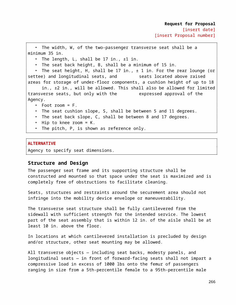
Request for Proposal[insert date]
[insert Proposal number]
it may incur to anyone as a result of acting as escrow agent under this Agreement, except for any loss, liability, damage or expense arising from the Escrow Agent’s fault. If Licensor or Licensee makes any payment (an “Indemnification Payment”) to the Escrow Agent pursuant to the provisions of the preceding sentence, then the party making the Indemnification Payment (the “Paying Party”) shall be entitled to contribution from the other (the “Contributing Party”) in an amount such that following contribution by the Contributing Party, the Paying Party and the Contributing Party shall each bear the portion of the Indemnification Payment as is proportionate to the relative fault of each of them with respect to the event that gave rise to the Indemnification Payment; provided, however, that if neither the Paying Party nor the Contributing Party is at fault, the Paying Party shall be entitled to contribution from the Contributing Party in an amount equal to one-half of the Indemnification Payment. The provisions of the preceding sentence shall not in any way limit the liability of Licensor or Licensee to the Escrow Agent pursuant to the second sentence of this Section 5 or any other provision of this Agreement.
6. GOOD FAITH RELIANCE
The Escrow Agent may rely and act upon written instructions, instruments or signatures believed by the Escrow Agent in good faith to be genuine and may assume that any person purporting to give any written notice, respect, advice or instruction in connection with or relating to this Escrow Agreement has been duly authorized to do so. The Escrow Agent’s duties shall be determined with respect to this Agreement and applicable laws only, and the Escrow Agent is not charged with knowledge of or duties under any other document, including the License Agreement.
7. FEES
(a) In consideration of performing its functions as Escrow Agent, the Escrow Agent shall be compensated as set forth on Exhibit C. The fees set forth on Exhibit C will be billed periodically by the Escrow Agent to:
___________________________________________________
___________________________________________________
(b) The fees set forth in Exhibit C are for ordinary services as escrow holder. In the event the Escrow Agent is required to incur any additional or extraordinary legal fees as a result of being escrow holder, including intervention in any litigation or proceeding, the Escrow Agent shall receive full compensation for any such reasonable legal fees that are documented to the Licensor and/or Licensee’s satisfaction.
8. ARBITRATION
Any dispute or controversy between Licensor and Licensee regarding the release of the Documentation shall be settled by arbitration to be held in the City of (insert city and state), in accordance with the rules of the American Arbitration Association.
Licensor and Licensee shall jointly select an arbitrator within 10 (ten) days following the giving of a counter-notice under Section 3(c) hereof. If during that 10 (ten) day period, Licensor and Licensee do not jointly select an arbitrator, then the arbitrator shall be administratively appointed by the (insert city and state) Regional Office of the American Arbitration Association, and neither the Licensor nor Licensee shall have the right to object to such appointment. Any arbitration pursuant to this Section 8 shall be conducted on an expedited basis and shall be binding upon Licensor and Licensee. Licensor and Licensee shall use their respective best efforts to conclude such arbitration within 45 (forty-five) days from the date an arbitrator is elected pursuant to this Section 8. The prevailing party in any arbitration pursuant to this Section 8 shall be entitled to recover from the other party all reasonable out-of-pocket expenses in connection with such arbitration including but not limited to the fees of the arbitrator, reasonable legal fees and disbursements and business-class travel and lodging expenses. Escrow Agent shall be entitled to fully rely upon the decision and rulings of such arbitrator.
268

Request for Proposal[insert date]
[insert Proposal number]
9. ENTIRE AGREEMENT
This Escrow Agreement, including Exhibits A, B and C hereto, constitutes the entire agreement among the parties concerning the subject matter hereof and shall supersede all previous communications, representations, understandings and agreements, either oral or written among the parties. This Escrow Agreement is intended to be and shall be treated as an agreement separate and distinct from the License Agreement.
10. NOTICE
All notices required or permitted by this Escrow Agreement shall be sufficiently served by mailing the same by certified or registered mail, return receipt requested, to the parties at their respective addresses, as follows:
(a) Escrow Agent:
__________________________________________
__________________________________________
__________________________________________
Attn: ______________________________________
Ref: _______________________________________
(b) Licensor:
__________________________________________
__________________________________________
__________________________________________
Attn: ______________________________________
(c) Licensee:
__________________________________________
__________________________________________
__________________________________________
Attn: ______________________________________
11. COUNTERPARTS
This Escrow Agreement may be executed in one or more counterparts, each of which shall be deemed an original, and all of which taken together shall constitute one and the same instrument.
269
Request for Proposal[insert date]
[insert Proposal number]
12. GOVERNING LAW
This Escrow Agreement shall be governed by and construed in accordance with the laws of the State of (insert state), without regard to its choice-of-laws or conflicts-of-law provisions.
13. SEVERABILITY
In the event any of the provisions of this Escrow Agreement shall be held by a court of competent jurisdiction to be contrary to any state or federal law, the remaining provisions of this Escrow Agreement will remain in full force and effect.
14. HEADINGS
The section headings in this Escrow Agreement do not form a part of it, but are for convenience only and shall not limit or affect the meaning of the provisions.
15. MISCELLANEOUS
(a) If in doubt as to its duties hereunder, Escrow Agent may consult with counsel of its choice.
(b) Nothing in this Agreement shall impose on the Escrow Agent the duty to qualify to do business or act as fiduciary in any jurisdiction other than
IN WITNESS WHEREOF, the parties have executed this Escrow Agreement on the date first above written.
As Escrow Agent: ______________________________________________________________ Name and title
________________________________________________________ __________________Signature Date
As Licensor: ___________________________________________________________________ Name and title
________________________________________________________ __________________Signature Date
As Licensee: ___________________________________________________________________ Name and title
________________________________________________________ __________________Signature Date
270
Request for Proposal[insert date]
[insert Proposal number]
EXHIBIT ADOCUMENTATIO N
271
Request for Proposal[insert date]
[insert Proposal number]
EXHIBIT BCERTIFICATE AS TO DEPOSIT OF ADDITIONAL SOURCE CODES
__________________________________________ (“Licensor”) hereby certifies to __________________________________________ (“Licensee) that Licensor has delivered to Escrow Agent on _________________________, 20__, to be held in escrow pursuant to the terms of the Escrow Agreement dated as of ____________________________, 20__, among Licensor, Licensee and Escrow Agent, one copy of each of the following Source Codes:
(Describe Source Codes)
Dated: ________________________________, 20__
CONTRACTORas Licensor: ___________________________________________________________________ Name and title
________________________________________________________ __________________Signature Date
272
Request for Proposal[insert date]
[insert Proposal number]
EXHIBIT CFEES
273
Request for Proposal[insert date]
[insert Proposal number]
EXHIBIT D
[Insert Form of License Agreement per Introductory paragraph of Escrow Agreement]
274
Request for Proposal[insert date]
[insert Proposal number]
ReferencesSAE # Title Date Published
J10 Methods of Test for Paints - Part J10: Determination of Deposition Efficiency of Coating Powders Sep 15, 1998J211 Instrumentation for Impact Test—Part 2: Photographic Instrumentation May 1, 2001J287 Driver Hand Control Reach Feb 1, 2007J366 Exterior Sound Level for Heavy Trucks and Buses Feb 1, 1987J382 Windshield Defrosting Systems Performance Requirements - Trucks, Buses, and Multipurpose
Vehicles.Jan 1, 1994
J534 Lubrication Fittings May 1, 2008J537 Storage Batteries Sep 1, 2000J541 Voltage Drop for Starting Motor Circuits Oct 1, 1996J587 License Plate Illumination Devices (Rear Registration Plate Illumination Devices) Sep 1, 2003J593 Backup Lamps (Reversing Lamps) Sep 1, 2005J673 Automotive Safety Glasses Oct 1, 2005J680 Location and Operation of Instruments and Controls in Motor Truck Cabs, Recommended Practice Sep 1, 1988J686 Motor Vehicle License Plates Oct 1, 1999J689 Curbstone Clearance, Approach, Departure, and Ramp Breakover Angles—Passenger Car and
Light TruckAug 1, 2009
J833 Human Physical Dimensions May 1, 2003J844 Nonmetallic Air Brake System Tubing Nov 1, 2004J941 Motor Vehicle Drivers’ Eye Locations Mar 1, 2010J994 Alarm—Backup—Electric Laboratory Performance Testing Mar 1, 2009J1050 Describing and Measuring the Driver's Field of View Jan 1, 2003J1113 Electromagnetic Compatibility Component Test Procedure Part 42, Conducted Transient Emissions Oct 1, 2006J1127 Low Voltage Battery Cable Mar 1, 2010J1128 Low Voltage Primary Cable Dec 1, 2005J1149 Metallic Air Brake System Tubing and Pipe Aug 1, 2007J1292 Automobile and Motor Coach Wiring Jan 1, 2008J1455 Recommended Environmental Practices for Electronic Equipment Design in Heavy-Duty Vehicle
ApplicationsJun 1, 2006
J1587 Joint SAE/TMC Electronic Data Interchange between Microcomputer Systems in Heavy-Duty Vehicle Applications, Recommended Practice
Jan 1, 1996
J1708 Serial Data Communications Between Microcomputer Systems in Heavy-Duty Vehicle Applications Oct 1, 2008J1986 Balance Weight and Rim Flange Design Specifications, Test Procedures, and Performance
RecommendationsJan 1, 2006
J1939 Data Link Layer Dec 1, 2006J1995 Engine Power Test Code - Spark Ignition and Compression Ignition - Gross Power Rating,
Standard;Jun 1, 1990
J2402 Road Vehicles—Symbols for Controls, Indicators, and Tell-tales Jan 1, 2010J2711 Recommended Practice for Measuring Fuel Economy and Emissions of Hybrid-Electric and
Conventional Heavy-Duty VehiclesSept 1, 2002
275

Request for Proposal[insert date]
[insert Proposal number]
Abbreviation and AcronymsA/C air conditioningABS anti-lock braking systemAC alternating currentACQ alkaline copper quaternaryADA Americans with Disabilities ActAh amp hourALR auto-locking retractorAPA The Engineered Wood Association, formerly the American Plywood AssociationAPC automatic passenger counterAPTA American Public Transportation AssociationASTM ASTM International, formerly the American Society for Testing and MaterialsATC automatic traction controlAVL automatic vehicle locationAWG American Wire GaugeBAFO Best and Final OfferBMS Battery Management SystemBRT bus rapid transitCARB California Air Resources BoardCCS climate control systemCCTV closed-circuit televisioncfm cubic feet per minuteCGA Compressed Gas AssociationCNG compressed natural gasdB decibelDBE disadvantaged business enterpriseDC direct currentDDU driver display unitDEF diesel exhaust fluidDOT Department of TransportationDPF diesel particulate filterECM Engine Control and MonitoringECS emission control systemELR emergency locking retractorEMI electromagnetic interferenceEPA Environmental Protection AgencyESS energy storage systemFEA Finite Element AnalysisFEMA failure mode effects analysisFMCSA Federal Motor Carrier Safety AdministrationFMCSR Federal Motor Carrier Safety RegulationsFMVSS Federal Motor Vehicle Safety StandardsFTA Federal Transit AdministrationGAWR gross axle weight ratedGPS global positioning systemGVW gross vehicle weightGVWR gross vehicle weight ratedH-point hip-point
276

Request for Proposal[insert date]
[insert Proposal number]
HDS hybrid drive systemHMI human-machine interfaceHSC hybrid system controllerHV high voltageHVAC heating, ventilation and air conditioningI/O input/outputIEEE Institute of Electrical and Electronics EngineersISO International Standards OrganizationLEL LED emergency lightLV low voltagemA milliampereMDT mobile data terminalMPa mega-PascalNC normally closedNFPA National Fire Protection AssociationNGV natural gas vehicleNOx nitrogen oxideNO normally openNTP notice to proceedOEM original equipment manufacturerOSI Open Systems InterconnectPA public addressPMO project management oversightPPU primary propulsion unitPPU prime power initPPV price per vehiclePRD pressure relief devicepsi pounds per square inchRF radio frequencyRFI radio frequency interferenceRTC real-time clockSAE SAE International, formerly the Society of Automotive Engineersscf standard cubic feetSLW seated load weightSOC state of changeUL Underwriters LaboratoriesUNECE United Nations Economic Commission for EuropeVDC volts of direct currentWh watt-hoursVIN vehicle information number
277