Embed Size (px)
Citation preview

APT Weather Station Reception on 137MHz with a Patch Antennaand DVB-T Stick
By Gunthard Kraus, DG8GB
First published in the German UKW Berichte journal 4/2014
This idea arose while browsing The Internet and finding a homepage with weather imagesreceived from a satellite. So I thought how I could do that with existing equipment - and whatwould need to be developed. This article is the result of a revised and expanded lecture given at the2014 VHF conference in Weinheim
1 Introduction
Such projects always start with an extensive planning phase to find the shortest route to thedestination. It soon became clear that the following modules, already available from completeddevelopments, could be used:
a. A commercially available DVB-T Stick as measuring receiver [1] and [2] b. A very low noise preamplifier with sufficient gain described in [3].
New ground was broken for the antenna used for this project. The author has already implementednumerous patch antenna projects successfully and has repeatedly published the correspondingdevelopment procedures. This kind of antenna offers a circular polarised design with its sphericalradiation pattern. For this purpose, the back (in this case: the underside!) forms a perfect shieldagainst the ground and you can even place the antenna directly flat on the ground. The "halfwavelength", approximately 1 metre edge length in the 2m band, required for this project presents abig hurdle and is discussed later.
The concept finally implemented is shown in Fig 1 and shows what items need to be developed. Thepatch antenna and a narrow band 137MHz bandpass filter need to be developed. The fact that variouscomputer programs also have to be used successfully is aptly described by the biblical quotation"every day has its own plague".
Fig 1: From now on probably the most basic receivers will look like this: an analog front endfollowed by digital signal processing feeding a USB port
2 The components of the receiver
2.1. The low noise preamplifier
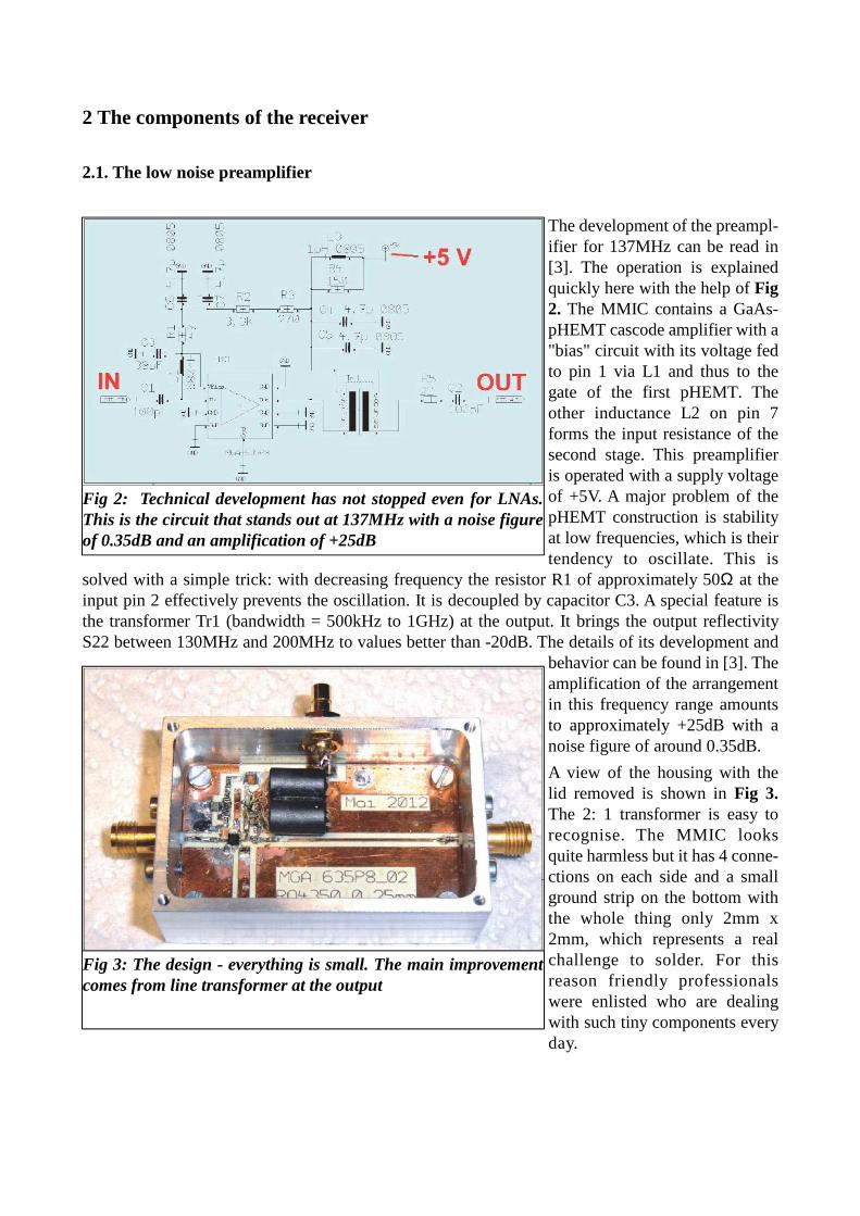
The development of the preampl-ifier for 137MHz can be read in[3]. The operation is explainedquickly here with the help of Fig2. The MMIC contains a GaAs-pHEMT cascode amplifier with a"bias" circuit with its voltage fedto pin 1 via L1 and thus to thegate of the first pHEMT. Theother inductance L2 on pin 7forms the input resistance of thesecond stage. This preamplifieris operated with a supply voltageof +5V. A major problem of thepHEMT construction is stabilityat low frequencies, which is theirtendency to oscillate. This is
solved with a simple trick: with decreasing frequency the resistor R1 of approximately 50Ω at theinput pin 2 effectively prevents the oscillation. It is decoupled by capacitor C3. A special feature isthe transformer Tr1 (bandwidth = 500kHz to 1GHz) at the output. It brings the output reflectivityS22 between 130MHz and 200MHz to values better than -20dB. The details of its development and
behavior can be found in [3]. Theamplification of the arrangementin this frequency range amountsto approximately +25dB with anoise figure of around 0.35dB.
A view of the housing with thelid removed is shown in Fig 3.The 2: 1 transformer is easy torecognise. The MMIC looksquite harmless but it has 4 conne-ctions on each side and a smallground strip on the bottom withthe whole thing only 2mm x2mm, which represents a realchallenge to solder. For thisreason friendly professionalswere enlisted who are dealingwith such tiny components everyday.
Fig 2: Technical development has not stopped even for LNAs.This is the circuit that stands out at 137MHz with a noise figureof 0.35dB and an amplification of +25dB
Fig 3: The design - everything is small. The main improvementcomes from line transformer at the output
2.2. The 137MHz bandpass filter
This should protect the input of the DVB-T Stick from strong "out-of-band" signals, which lead tooverdriving or intermodulation. The Stick inputs are not exactly famous for extremely high intermo-dulation strength, even when heavily limited.
As usual this presents a dilemma: a higher filter degree gives steeper flanks and greater selectivity,but more components need more space, and the limited space leads to considerable attenuation. Thesame milled aluminium housing as used for the LNA (PCB size: 30mm x 50mm) is used for thebandpass filter. On this board, a maximum of 4 shielded filter coils (NEOSID type 10.1) as well as 4
SMD trimming capacitors must be accom-modated for fine adjustment. Therefore, the"Coupled Resonator Type" was used as thebasic circuit because:
a. It allows small bandwidths andsteep filter edges with realisticcomponent values. b. A design can be carried out easilywith the filter calculator providedfree of charge in the ANSOFTDESIGNER SV software.
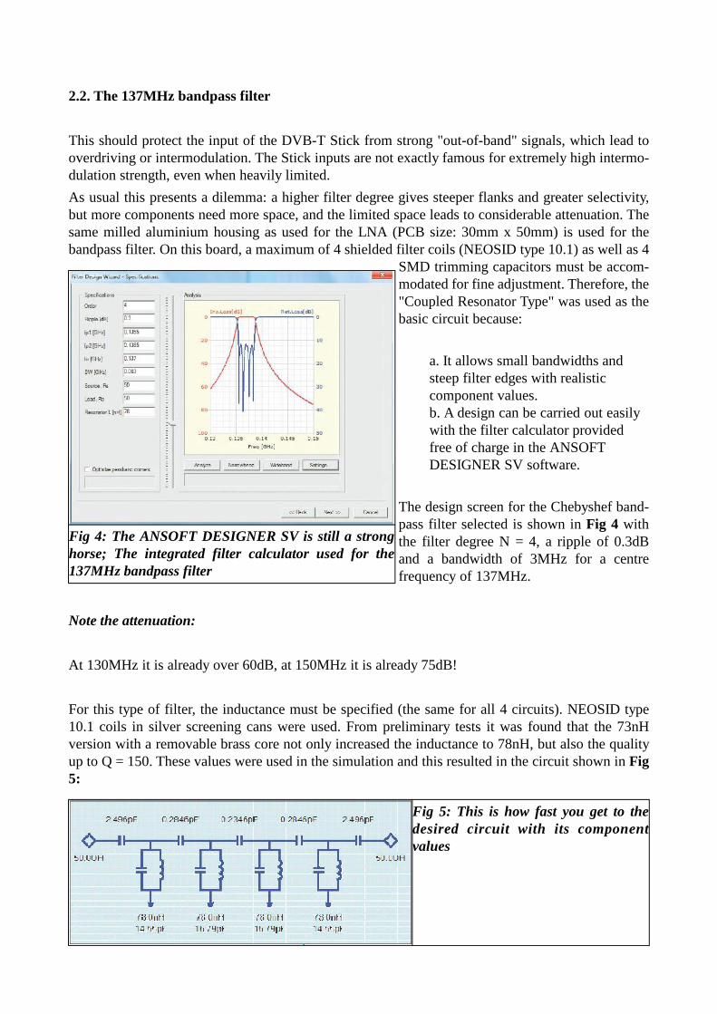
The design screen for the Chebyshef band-pass filter selected is shown in Fig 4 withthe filter degree N = 4, a ripple of 0.3dBand a bandwidth of 3MHz for a centrefrequency of 137MHz.
Note the attenuation:
At 130MHz it is already over 60dB, at 150MHz it is already 75dB!
For this type of filter, the inductance must be specified (the same for all 4 circuits). NEOSID type10.1 coils in silver screening cans were used. From preliminary tests it was found that the 73nHversion with a removable brass core not only increased the inductance to 78nH, but also the qualityup to Q = 150. These values were used in the simulation and this resulted in the circuit shown in Fig5:
Fig 4: The ANSOFT DESIGNER SV is still a stronghorse; The integrated filter calculator used for the137MHz bandpass filter
Fig 5: This is how fast you get to thedesired circuit with its componentvalues

Up to three 0603 NPO SMD capacitorswith a trimmer (1.4 ... .3.5pF) were conn-ected in parallel as circuit capacitors.Each "coupling capacitor" of 2.49pF con-sists of a parallel connection of 1.5pF and1pF in SMD capacitors soldered together"piggy back". The actual coupling capaci-tors consist of finger-shaped printed "inte-rdigital capacitors" whose design was car-ried out with the help of the ANSOFTDESIGNER SV and the circuit principleshown in Fig 6:
A half-bridge is used, often found in crystal filters, and the dimensions of the interdigital capacitorare changed until an S21 value below -70dB is obtained at 137MHz. The capacitance value of0.2846pF (or 0.2346pF for the middle coupling capacitor) is correct.
The following considerations were made for the mechanical dimensions of this structure:
a. The distances between the fingers should not be a headache for the PCB manufacturer, so0.25 mm was chosen. b. In order not to make the finished capacitor too large, a finger width of 0.5mm was used. c. The complete arrangement should be approximately a square. This finally yields therequired number of fingers (here: N = 4) and the length of the fingers calculated for thispurpose.
This leads to the property table shown in Fig 7. The mechanical dimensions for the circuit boardlayout of the finished interdigital capacitor canbe derived from this.
Now it is exciting, because in the simulationcircuit the fixed capacitors are now replaced bythese interdigital versions. This is followed by aconsolidation phase. Each interdigital capacitorhas an additional capacitance to ground show inthe equivalent circuit diagram as a pi-circuit ateach end. These parallel capacitors de-tune theresonant circuits so you have to correct and sim-ulate again until you finally have the resultshown in Fig 8. The final circuit is shown in Fig9 and the finished circuit board layout in Fig 10.
Fig 6: This ideas must be used: The mechanical data forthe interdigital capacitor can only be determined withthis "half-bridge" technique (seetext)
Fig 7: This list of capacitor dimen-sions is needed later on for the cir-cuit board layout
Fig 8: This is the dream result. Everything shouldend up like this!
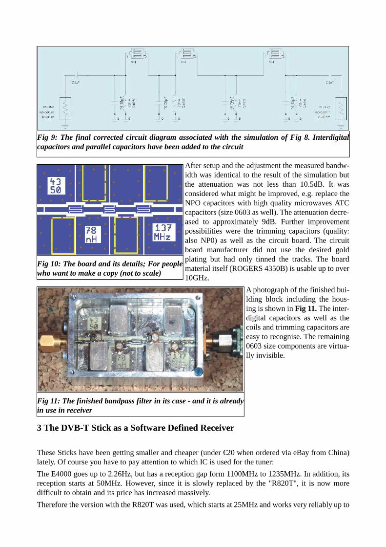
After setup and the adjustment the measured bandw-idth was identical to the result of the simulation butthe attenuation was not less than 10.5dB. It wasconsidered what might be improved, e.g. replace theNPO capacitors with high quality microwaves ATCcapacitors (size 0603 as well). The attenuation decre-ased to approximately 9dB. Further improvementpossibilities were the trimming capacitors (quality:also NP0) as well as the circuit board. The circuitboard manufacturer did not use the desired goldplating but had only tinned the tracks. The boardmaterial itself (ROGERS 4350B) is usable up to over10GHz.
A photograph of the finished bui-lding block including the hous-ing is shown in Fig 11. The inter-digital capacitors as well as thecoils and trimming capacitors areeasy to recognise. The remaining0603 size components are virtua-lly invisible.
3 The DVB-T Stick as a Software Defined Receiver
These Sticks have been getting smaller and cheaper (under €20 when ordered via eBay from China)lately. Of course you have to pay attention to which IC is used for the tuner:
The E4000 goes up to 2.26Hz, but has a reception gap form 1100MHz to 1235MHz. In addition, itsreception starts at 50MHz. However, since it is slowly replaced by the "R820T", it is now moredifficult to obtain and its price has increased massively.
Therefore the version with the R820T was used, which starts at 25MHz and works very reliably up to
Fig 9: The final corrected circuit diagram associated with the simulation of Fig 8. Interdigitalcapacitors and parallel capacitors have been added to the circuit
Fig 10: The board and its details; For peoplewho want to make a copy (not to scale)
Fig 11: The finished bandpass filter in its case - and it is alreadyin use in receiver
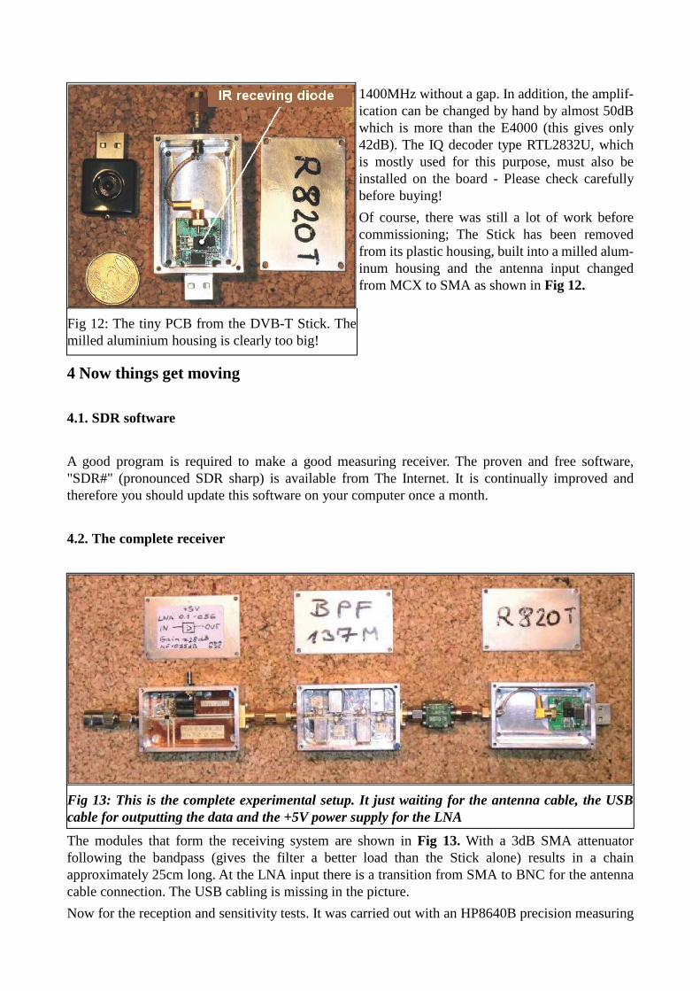
1400MHz without a gap. In addition, the amplif-ication can be changed by hand by almost 50dBwhich is more than the E4000 (this gives only42dB). The IQ decoder type RTL2832U, whichis mostly used for this purpose, must also beinstalled on the board - Please check carefullybefore buying!
Of course, there was still a lot of work beforecommissioning; The Stick has been removedfrom its plastic housing, built into a milled alum-inum housing and the antenna input changedfrom MCX to SMA as shown in Fig 12.
4 Now things get moving
4.1. SDR software
A good program is required to make a good measuring receiver. The proven and free software,"SDR#" (pronounced SDR sharp) is available from The Internet. It is continually improved andtherefore you should update this software on your computer once a month.
4.2. The complete receiver
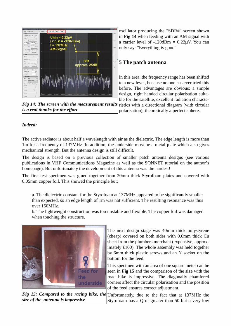
The modules that form the receiving system are shown in Fig 13. With a 3dB SMA attenuatorfollowing the bandpass (gives the filter a better load than the Stick alone) results in a chainapproximately 25cm long. At the LNA input there is a transition from SMA to BNC for the antennacable connection. The USB cabling is missing in the picture.
Now for the reception and sensitivity tests. It was carried out with an HP8640B precision measuring
Fig 12: The tiny PCB from the DVB-T Stick. Themilled aluminium housing is clearly too big!
Fig 13: This is the complete experimental setup. It just waiting for the antenna cable, the USBcable for outputting the data and the +5V power supply for the LNA
oscillator producing the "SDR#" screen shownin Fig 14 when feeding with an AM signal witha carrier level of -120dBm = 0.22µV. You canonly say: "Everything is good"
5 The patch antenna
In this area, the frequency range has been shiftedto a new level, because no one has ever tried thisbefore. The advantages are obvious: a simpledesign, right handed circular polarisation suita-ble for the satellite, excellent radiation characte-ristics with a directional diagram (with circularpolarisation), theoretically a perfect sphere.
Indeed:
The active radiator is about half a wavelength with air as the dielectric. The edge length is more than1m for a frequency of 137MHz. In addition, the underside must be a metal plate which also givesmechanical strength. But the antenna design is still difficult.
The design is based on a previous collection of smaller patch antenna designs (see variouspublications in VHF Communications Magazine as well as the SONNET tutorial on the author’shomepage). But unfortunately the development of this antenna was the hardest!
The first test specimen was glued together from 20mm thick Styrofoam plates and covered with0.05mm copper foil. This showed the principle but:
a. The dielectric constant for the Styrofoam at 137MHz appeared to be significantly smallerthan expected, so an edge length of 1m was not sufficient. The resulting resonance was thusover 150MHz. b. The lightweight construction was too unstable and flexible. The copper foil was damagedwhen touching the structure.
The next design stage was 40mm thick polystyrene(cheap) covered on both sides with 0.6mm thick Cusheet from the plumbers merchant (expensive, approx-imately €100). The whole assembly was held togetherby 6mm thick plastic screws and an N socket on thebottom for the feed.
This specimen with an area of one square meter can beseen in Fig 15 and the comparison of the size with theroad bike is impressive. The diagonally chamferedcorners affect the circular polarisation and the positionof the feed ensures correct adjustment.
Unfortunately, due to the fact that at 137MHz theStyrofoam has a Q of greater than 50 but a very low
Fig 14: The screen with the measurement resultsis a real thanks for the effort
Fig 15: Compared to the racing bike, thesize of the antenna is impressive

dielectric constant of only 1.05 meant that the previously selected radiator dimensions were still toosmall and the resonant frequency was still at 152MHz instead of 137MHz!
For the third design a polyethylene plate with a surface area of 1m2 and a thickness of 15mm waspurchased from The Internet (price: approximately €100, weight over 10 kg) complete with electricaldata. The total antenna weight (for plate and copper on both sides) has unfortunately increased toabout 20kg.
The simulation data was:
Polyethylene with a thickness of 15mmDielectric constant = 2.4Loss factor = 0.005
It was simulated in a box with a base area of 9m x 9m (comes from the SONNET requirement"distance of the structure from the box wall everywhere about 2 wavelengths”). Above the antennathere is an air cushion with the height "Half wavelength = 1.1 metre". The box lid is set to "FreeSpace". The patch itself is 730mm x 730mm, the diagonal corners are trimmed by 75mm (to achievethe right hand circular polarisation). An N type connector on the lower "ground" level was providedas feed connection. A pin made on the lathe extends through the polyethylene plate and was solderedto the socket and the patch. This is taken into account using a "Via" with a diameter of 5mm in theSONNET simulation.
The corresponding SONNET editor screen andthe feed point used are shown in Fig 16: (Feed =355mm in horizontal and 180mm in verticaldirection from the lower left corner).
The simulated antenna structure (Fig 17) beginswith the bottom of the box as an infinitely goodconducting ground plane. Followed by the poly-ethylene layer with a thickness of 15mm. A1mm thick air layer was inserted between thelowest "ground" layer and the polyethylenebecause the copper sheets did not lay flat every-where - especially when the thing curled by itsown weight. It quickly became apparent that thefree, but limited SONNET Lite version has its
Fig 16: Something from "SONNET Lite". Infor-mation about the design sequence. This is theinput screen with the antenna array
Fig 17: From the "Dielectric Layers"menu (see text)

limitations: the lower ground plane of the antenna is notinfinite in size; the size of the polyethylene used for thesimulation should only be as large as the area of theantenna; the "space" contained lots of plastic screws; etc.The simulation was carried out with a "cell size” of 5mmx 5mm.
The very pleasing S11 simulation result is shown as aSmith Chart in Fig 18 and as a Cartesian diagram in Fig19. These almost match the measured results of the comp-leted antenna shown in Fig 20. However, the author mustconfess that "fine tuning" was necessary. The patch dime-nsions were quite accurate because the resonance wasexactly at 137 MHz BUT: the cut-off at the corners wastoo much and as with a clearly over critically bandpassfilter, the S11 bandwidth was much too large combined
with a very deep "hole" at the centre frequency.
So, "fine tuning" was performed with sheet metal pieces brazed to the corners to give a cut off of40mm instead of 75mm. This resulted in the S11 curve shown in Fig 20. It was measured at the input
of the antenna feed line (5 metre long RG58Ucable) with an HP8410 network analyser
6 Finally it is finished!
Now the time had come: the antenna was placedin the garden on two plastic buckets. An RG58cable approximately 5m long was pulled thro-ugh the basement window into the basementworkshop (Fig 21) and connected to the recei-ver. The "SDR#” software was started on thenotebook and tuned to 137MHz.
Fig 19: The cartesian diagram also shows theS11 behavior, this time in dB
Fig 18: The S11 curve is very satisfactory.Shown in Smith chart
Fig 20: The S11 measurement on thefinished antenna is satisfying, but onlyafter the corresponding fine tuning
Fig 21: Now it's serious! The antenna is installedin the garden in front of the cellar workshop, theantenna cable (5m RG58) disappears through thecellar window
And what was to be seen?
Only an insane noise level, which was at least 30dBhigher than the one described in chapter 3.2.Individual carriers appeared briefly that were recorded as AM signals and on the basis of the shortmessages, e.g. "Hello Lufthansa Flight 309 ..." they could be identified as an air traffic announceme-nts from the airport tower at Friedrichshafen. After a lot of experiments there was only onepossibility: try again either very late in the evening or very early in the morning and hope that no"Man Made Noise" obliterates all interesting signals.
A search at 5 o’clock the next morning was successful: suddenly on 137MHz there was a clear FMsignal seen on the spectrum display with approximately 35kHz bandwidth. The chirping andwhistling used for APT transmissions was heard loud and clear from the PC loudspeaker. So it wasquickly recorded as a “WAV file” using the "SDR#" "Recording" and "Audio" options. 10 minuteslater the energy saving lamps belonging to a neighbour went on and the noise level rose by 15dB.Therefore, a more practical solution is still required e.g. antenna mounted at the highest point of thehouse roof. One possibility is directly under the roof and just above the desktop computer in thestudy on the upper floor.
7 The evaluation, the return for all the work
The received signals wereevaluated later using thefree software "WXtolmg"downloaded from The Inte-rnet.
If reception is always perf-ect you should downloadanother program (e.g. from"www.VBCABLE.com"),which serves as a "virtualaudio cable" and directlyconnects the "SDR#" and"WXtolmg". This allowsthe weather image to be dis-played directly on the PCscreen without delay duringreception.
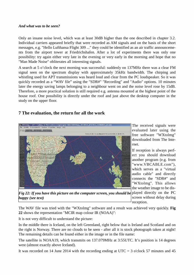
The WAV file was tried with the "WXtolmg" software and a result was achieved very quickly. Fig22 shows the representation "MCIR map colour IR (NOAA)":
It is not very difficult to understand the picture:
In the middle there is Iceland, on the left Greenland, right below that is Ireland and Scotland and onthe right is Norway. There are no clouds to be seen - after all it is stock photograph taken at night!The remaining details can be found either in the image or in the file name:
The satellite is NOAA19, which transmits on 137.079MHz at 3:55UTC. It’s position is 14 degreeswest (almost exactly above Iceland).
It was recorded on 14 June 2014 with the recording ending at UTC = 3 o'clock 57 minutes and 45
Fig 22: If you have this picture on the computer screen, you should behappy (see text)
seconds. The receptionlevel was just under 0.2µV.After a calculation the dist-ance between my QTH andthe satellite is more than2000km, which is amazing.
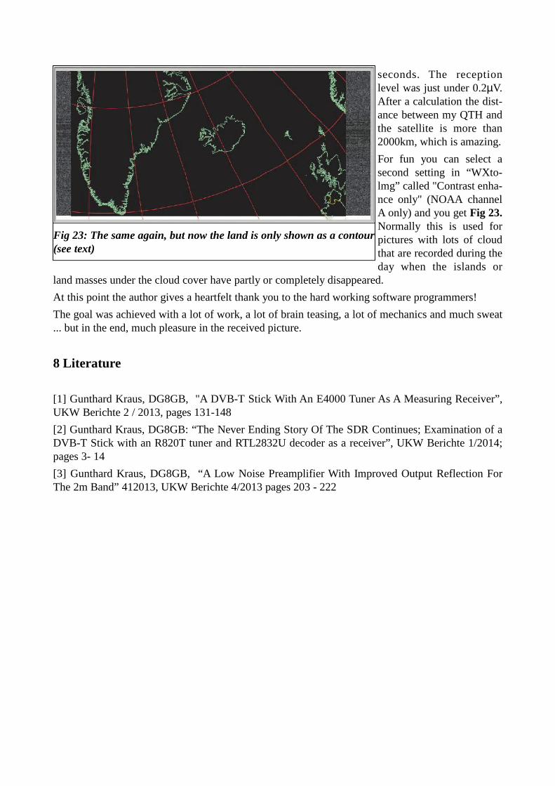
For fun you can select asecond setting in “WXto-lmg” called "Contrast enha-nce only" (NOAA channelA only) and you get Fig 23.Normally this is used forpictures with lots of cloudthat are recorded during theday when the islands or
land masses under the cloud cover have partly or completely disappeared.
At this point the author gives a heartfelt thank you to the hard working software programmers!
The goal was achieved with a lot of work, a lot of brain teasing, a lot of mechanics and much sweat... but in the end, much pleasure in the received picture.
8 Literature
[1] Gunthard Kraus, DG8GB, "A DVB-T Stick With An E4000 Tuner As A Measuring Receiver”,UKW Berichte 2 / 2013, pages 131-148
[2] Gunthard Kraus, DG8GB: “The Never Ending Story Of The SDR Continues; Examination of aDVB-T Stick with an R820T tuner and RTL2832U decoder as a receiver”, UKW Berichte 1/2014;pages 3- 14
[3] Gunthard Kraus, DG8GB, “A Low Noise Preamplifier With Improved Output Reflection ForThe 2m Band” 412013, UKW Berichte 4/2013 pages 203 - 222
Fig 23: The same again, but now the land is only shown as a contour(see text)