Embed Size (px)
Citation preview

Installation and Reference Guide
2020 Voxx Electronics Corporation. All rights reserved. APS57TM_RevD_07/20
2 Wire Harness Colors and Functions 2 Power Connector 3 Notification Connector 4 Input / Output Connector
6 External Components 6 RF Antenna Kit 6 Data Bus Interface (DBI) 6 Telematics 6 Weblink Programming 7 Setup Options 7 Remote Programming 8 Keyless Control 10 Remote Start Control
14 System Operation 14 Remote Operation
APS57TM Vehicle Remote Start / Keyless System
15 System Programming 15 Programming Mode Entry / Exit 16 Feature Bank Options 17 Data Port Protocol 17 Tach Function 17 Alarm Override 18 Silent Lock and Unlock 18 User Selectable LED
18 System Diagnostics 18 Troubleshooting Remote Start
19 Wiring Diagrams 19 Door Lock Connections 22 Full System Connections
Thank you for trusting Prestige products! If you are a consumer, please note:Professional installation is strongly recommended.
This manual assumes the installer has adequate knowledge of the following expertise. Therefore, it does not cover these topics in detail: • 12-volt electronics • Testing and verifying circuits • Making safe and lasting wiring connections • Factory ignition, power, lighting, data bus and sensing systems • Factory systems and components to avoid • Safe wire routing, circuit protection and product placement • Access to vehicle-specific technical information
In addition, this manual assumes the installer has the proper tools, skill and facilities to perform a professional installation. Performing an improper installation could result in damage to the vehicle or its components, improper system function, unsafe vehicle operation or physical injury. Such instances would not be covered by the vehicle manufacturer's warranty, nor by Voxx Electronics, Inc.
Detailed Descriptions Quick Reference

APS57TM_RevA_07/202
Detailed Descriptions: Wire Harness Colors and Functions Power Connector (6-pin High-Current Connector) See page 22 for the full system diagram.
These wires are listed in order of their placement in the harness connector.
1. YELLOW – Starter Output for Remote Start (+)The YELLOW wire supplies 12-Volt (+) to the vehicle’s starter wire when remote start is enabled, and turns off once the vehicle is started.Verification: This starter wire registers 12-Volt (+) during engine crank.
3. RED – 12-Volt Input (+)The RED wire connects to the vehicle’s primary 12-Volt (+) wire to power the system. Verification: The power wire registers 12-Volt (+) at all times. Note: Before making this connection, remove all module fuses until the system is completely connected.
2. GREEN – Ignition 2 Output (+)At its default setting, the GREEN wire supplies 12-Volt (+) to the vehicle’s secondary ignition wire during remote start. Verification: If present, the secondary ignition wire registers 12-Volt (+) when the vehicle is in ignition mode AND during engine crank. Note: This wire can be programmed to perform a different function by changing its options. Refer to Bank 3, Feature 7 on page 10.
4. RED/WHITE – 12-Volt Input (+)The RED/WHITE wire connects to the vehicle’s secondary 12-Volt (+) wire to power the remote start function. Verification: The power wire registers 12-Volt (+) at all times. Note: Before making this connection, remove all module fuses until the system is completely connected.
1 3 5
2 4 6
6. BLUE – Ignition 1 Input / Output (+)The BLUE wire supplies 12-Volt (+) to the vehicle’s primary ignition wire during remote start. This wire is also used to sense vehicle ignition for the Programming FunctionsVerification: The primary ignition wire registers 12-Volt (+) when the vehicle is in ignition mode AND during engine crank.
5. PURPLE – Accessory Output (+)At its default setting, the PURPLE wire supplies 12-Volt (+) to the vehicle’s accessory wire to power vehicle accessories during remote start.Verification: The accessory wire registers 12-Volt (+) when the vehicle is running or in Accessory mode, but not during engine crank or if the vehicle is off. Note: This wire can be programmed to perform a different function by changing its options. Refer to Bank 3, Feature 9 on page 10.

APS57TM_RevA_07/20 3
Detailed Descriptions: Wire Harness Colors and Functions Notification Connector (4-pin connector) See page 22 for the full system diagram.
These wires are listed in order of their placement in the harness connector.
2. WHITE/RED – Parking Light Relay Input (Internal Relay Pin 87)The WHITE/RED connects to vehicle 12-Volt (+) or Ground (-) to supply the relay output (WHITE wire). Verification for default setting: • If the vehicle parking light wire registers 12-Volt (+) when the park lights are on, connect the WHITE/RED wire to a
constant 12-Volt (+) vehicle wire.• If the vehicle parking light wire registers Ground (-) when the park lights are on, connect the WHITE/RED wire to a
reliable vehicle ground source.
1. WHITE – Parking Light Relay Output (Internal Relay Pin 30)At its default setting, the WHITE wire supplies 12-Volt (+) or Ground (-) to the vehicle's park light wire based on the connection of the relay input (WHITE/RED wire).Verification: The vehicle parking light wire registers 12-Volt (+) or Ground (-) when the park lights are turned on.
4. BLACK – Ground Input (-)The BLACK wire connects to a reliable vehicle ground (-) source to power the system. Verification: The vehicle ground (-) source wire registers ground (-) at all times. Note: Before making this connection, remove all module fuses until the system is completely connected.
3. YELLOW/BLACK – Ignition Output to Alarm (+)The YELLOW/BLACK wire supplies 12-Volt (+) ignition output when the vehicle's ignition is set to ON, but not during the remote start runtime. This output will be used when an external alarm system is added to the vehicle.
1 32 4

APS57TM_RevA_07/204
Detailed Descriptions: Wire Harness Colors and Functions Input / Output Connector (14-pin connector) See page 22 for the full system diagram.
These wires are listed in order of their placement in the harness connector.
1
2
3 5 7 9 11 13
4 6 8 10 12 14
3. GRAY/BLACK – Hood Input (-)The GRAY/BLACK wire connects to the vehicle's hood switch, or an installed switch that registers Ground (-) when triggered.Verification: The vehicle hood switch wire registers Ground (-) when the hood is opened.
5. LIGHT BLUE – Remote Start Status Output (-)The LIGHT BLUE wire supplies Ground (-) as soon as the remote starter is activated and remains active until 4 seconds after remote start run time has ended. This wire is most commonly used to activate data integration modules.
1. BLACK/WHITE – Horn Output (-)The BLACK/WHITE wire connects to the vehicle's horn wire and supplies Ground (-) when activated from the system.Verification: The vehicle horn wire registers Ground (-) when the horn is activated.
9. BLACK/BLUE – Factory Disarm Output (-)The BLACK/BLUE wire supplies a Ground (-) pulse when the system is disarmed and when remote start is activated.Verification: In most vehicles the vehicle factory disarm wire registers Ground (-) if the driver door key cylinder is turned to the unlock position.Note: This wire can be programmed to perform a different function by changing its options. Refer to Bank 3, Feature 19 on page 10.
7. BLACK/LIGHT GREEN – Factory Arm Output (-)At its default setting, the BLACK/GREEN wire supplies a Ground (-) pulse when the system is armed and when the vehicle has been successfully started using remote start. It is typically used to re-lock vehicle doors after remote start if necessary.Note: This wire can be programmed to perform a different function by changing its options. Refer to Bank 3, Feature 21 on page 10.
6. DARK BLUE/BLACK -- External Start Input (-)The DARK BLUE/BLACK wire connects to a device or switch that, when triggered, supplies a Ground (-) output. If the vehicle ignition is off, this input will activate the remote start function.
8. BROWN/BLACK – Brake Input (+)The BROWN/BLACK wire connects to the vehicle's brake wire to supply brake status for remote start. Verification: The vehicle brake wire registers 12-Volts (+) when the brake is activated.
2. RED – Door Lock (-)The RED wire supplies Ground (-) when the Lock function is activated from the remote control or system.Verification: The vehicle lock wire registers 12-Volts (+) or Ground (-) when the Lock button is activated. Additional parts may be required. See Page 19 for common door lock wire diagrams.
4. GREEN – Door Unlock (-)The GREEN wire supplies Ground (-) when the Unlock function is activated from the remote control or system.Verification: The vehicle lock wire registers 12-Volt (+) or Ground (-) when the Unlock button is activated. Additional parts may be required. See Page 19 for common door lock wire diagrams.
APS57TM_RevA_07/20 5
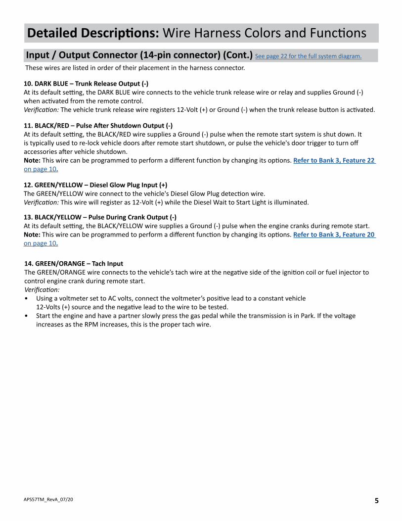
13. BLACK/YELLOW – Pulse During Crank Output (-)At its default setting, the BLACK/YELLOW wire supplies a Ground (-) pulse when the engine cranks during remote start.Note: This wire can be programmed to perform a different function by changing its options. Refer to Bank 3, Feature 20 on page 10.
14. GREEN/ORANGE – Tach InputThe GREEN/ORANGE wire connects to the vehicle’s tach wire at the negative side of the ignition coil or fuel injector to control engine crank during remote start.Verification: • Using a voltmeter set to AC volts, connect the voltmeter’s positive lead to a constant vehicle
12-Volts (+) source and the negative lead to the wire to be tested. • Start the engine and have a partner slowly press the gas pedal while the transmission is in Park. If the voltage
increases as the RPM increases, this is the proper tach wire.
12. GREEN/YELLOW – Diesel Glow Plug Input (+)The GREEN/YELLOW wire connect to the vehicle's Diesel Glow Plug detection wire.Verification: This wire will register as 12-Volt (+) while the Diesel Wait to Start Light is illuminated.
Detailed Descriptions: Wire Harness Colors and Functions Input / Output Connector (14-pin connector) (Cont.) See page 22 for the full system diagram.
These wires are listed in order of their placement in the harness connector.
11. BLACK/RED – Pulse After Shutdown Output (-)At its default setting, the BLACK/RED wire supplies a Ground (-) pulse when the remote start system is shut down. It is typically used to re-lock vehicle doors after remote start shutdown, or pulse the vehicle's door trigger to turn off accessories after vehicle shutdown. Note: This wire can be programmed to perform a different function by changing its options. Refer to Bank 3, Feature 22 on page 10.
10. DARK BLUE – Trunk Release Output (-)At its default setting, the DARK BLUE wire connects to the vehicle trunk release wire or relay and supplies Ground (-) when activated from the remote control. Verification: The vehicle trunk release wire registers 12-Volt (+) or Ground (-) when the trunk release button is activated.

APS57TM_RevA_07/206
Detailed Descriptions: External Components
RF Antenna / LED / Programming PortThe long-range antenna kit (included) plugs into a 6-pin connector on the Prestige module.
1. Mount the supplied antenna/receiver to a clear spot on the vehicle’s windshield that will not block the driver’s vision. A suitable location is high on the windshield near the rear-view mirror.
2. Be careful not to mount the antenna/receiver on any metallic window film, as this will affect system range.
3. Route the antenna/receiver cable to the Prestige module, ensuring it does not block or interfere with deployment of the airbag (if equipped.) Plug into the antenna port.
Data Bus Interface (DBI) PortThe 4-pin Data Bus Interface enables a FlashLogic door lock or transponder interface to connect to and communicate with the vehicle data bus. The combined system saves installation time as many features that normally require individual connection can be accessed and controlled through the data bus. Please refer to the D2D (Data to Data) function list available per vehicle at www.FlashLogic.com.
Telematics InterfaceThe 4-pin Telematics port enables a connected interface such as CarLink to expand system control to a smartphone or tablet. The following features may be able to be activated from a connected device: • Door Lock Control • Remote Start • Trunk Release • Auxiliary Output* • Sliding Doors*
Weblink ProgrammingThis port can also be used to connect your FlashLogic Weblink for feature programming and software updating. Once connected please visit www.flashlogic.com.
* Must be supported by FLCAN
FLCART Cartridge PortThis port is for installing the FlashLogic FLCART data immobilizer & door lock interface cartridge used to communicate with the vehicle’s databus.
Weblink Programming PortThis 4-pin port is used for programming the FlashLogic FLCART interface cartridge via the FLPROG Weblink or Weblink Mobile. Refer to the FlashLogic website for more details.
FLCART Harness PortThis port is for the harness included with the FLCART interface cartridge. Refer to the FlashLogic website for more details.
APS57TM_RevA_07/20 7
Detailed Descriptions: Setup Options
Bank 1: Add / Remove Remote Controls See page 15 for Programming Instruction.
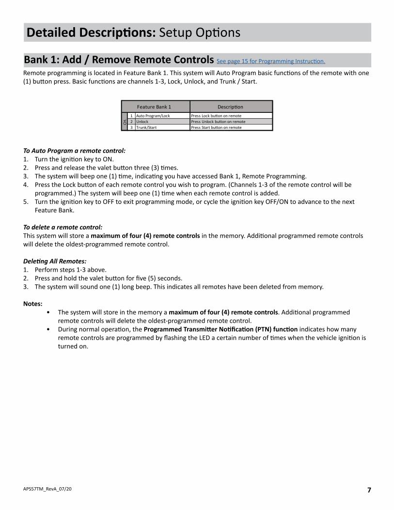
To Auto Program a remote control:1. Turn the ignition key to ON.2. Press and release the valet button three (3) times.3. The system will beep one (1) time, indicating you have accessed Bank 1, Remote Programming.4. Press the Lock button of each remote control you wish to program. (Channels 1-3 of the remote control will be
programmed.) The system will beep one (1) time when each remote control is added.5. Turn the ignition key to OFF to exit programming mode, or cycle the ignition key OFF/ON to advance to the next
Feature Bank.
To delete a remote control:This system will store a maximum of four (4) remote controls in the memory. Additional programmed remote controls will delete the oldest-programmed remote control.
Deleting All Remotes:1. Perform steps 1-3 above.2. Press and hold the valet button for five (5) seconds.3. The system will sound one (1) long beep. This indicates all remotes have been deleted from memory.
Notes:• The system will store in the memory a maximum of four (4) remote controls. Additional programmed
remote controls will delete the oldest-programmed remote control. • During normal operation, the Programmed Transmitter Notification (PTN) function indicates how many
remote controls are programmed by flashing the LED a certain number of times when the vehicle ignition is turned on.
Remote programming is located in Feature Bank 1. This system will Auto Program basic functions of the remote with one (1) button press. Basic functions are channels 1-3, Lock, Unlock, and Trunk / Start.
1 Auto Program/Lock2 Unlock3 Trunk/Start
Feature Bank 1 Descrip�on
CH.
Press Lock bu�on on remotePress Unlock bu�on on remotePress Start bu�on on remote

APS57TM_RevA_07/208
Detailed Descriptions: Setup OptionsKeyless Control (Bank 2) See page 15 for Programming Instruction.
Feature 1: Lock / Unlock FunctionFunction: Set the lock / unlock output timing and functionality for specific vehicle lock types. Setting Choices:
• Option 1 - Lock and Unlock outputs will pulse for 500 milliseconds.• Option 2 - Lock and Unlock outputs will pulse for 3.5 seconds.• Option 3 - Lock output will pulse for 500ms ; Unlock output will pulse twice, 500ms each.• Option 4 - Lock output will pulse twice, 500ms each ; Unlock output will pulse for 500ms. • Option 5 - Lock and Unlock outputs will pulse twice for 500ms.• Option 6 - Lock output will pulse for 500ms ; Unlock output will pulse for 350ms.
Feature 2: Accessory-Activated LockThis Feature is not available on this model.
Feature 3: Accessory-Activated UnlockThis Feature is not available on this model.
Feature 4: Exterior IlluminationThis Feature is not available on this model.
1 Chirp 2 Chirp 3 Chirp 4 Chirp 5 Chirp 6 Chirp1 Lock / Unlock Func�on 500ms 3.5sec 500ms L, DBL UL DBL L, 500ms UL DBL L, DBL UL 500ms L, 350ms UL2 Accessory Lock NA3 Accessory Unlock NA4 Exterior Il lumina�on NA5 Auto Relock NA6 Auto Arming NA7 No�fica�on Sound NA8 Horn Timing 16ms 30ms 40ms 50ms 10ms9 Valet Override Method NA
10 Driver Priority Unlock NA11 Silent Choice OFF From Transmi�er OEM Style12 Park Light / Trunk Swap NA13 AUX Ch. 4 NA14 AUX Ch. 5 NA15 AUX Ch. 6 NA16 AUX Ch. 7 NA17 Security Profi le OFF OEM Security W/ OEM Remote Start
18 Data Port Protocol ADS DBI
Feature Bank 2 Op�ons
Feat
ures
Feature 7: Notification SoundsThis feature is not available on this model.
Feature 6: Automatic ArmingThis feature is not available on this model.
Feature 5: Auto ReLock SettingThis Feature is not available on this model.

APS57TM_RevA_07/20 9
Detailed Descriptions: Setup OptionsKeyless Control (Bank 2) (cont.) See page 15 for Programming Instruction.
Feature 9: Override MethodThis feature is not available on this model.
Feature 8: Horn Output DurationFunction: Set the horn output to activate for a set time.Setting Choices:
• Option 1 - Output pulses for 16 milliseconds.• Option 2 - Output pulses for 30 milliseconds.• Option 3 - Output pulses for 40 milliseconds.• Option 4 - Output pulses for 50 milliseconds.• Option 5 - Output pulses for 10 milliseconds.
Feature 17: Security ProfileFunction: Set the system to function as a keyless entry / convenience system or full-featured alarm / convenience system. Setting Choices:
• Option 1 - OFF, no security protection.• Option 2 - OEM Security, entry zone protection.• Option 3 - w/ OEM Remote Start, entry zone protection with OEM remote start compatibility.
Feature 10: Driver Priority UnlockThis Feature is not available on this model.
Feature 11: Silent ChoiceTM
Function: Set audible beeps on or off when arming and disarming the system. Setting Choices:
• Option 1 - Pressing Lock or Unlock at any time will perform the function with audible beeps.• Option 2 - Pressing Lock or Unlock for 1.5sec on remote will control system without an audible beep.• Option 3 - First press of Lock or Unlock on the remote control will perform the function without an audible
sound. Second press within 10sec will result in audible beeps.
Feature 12: Park Light / Trunk Relay FunctionThis Feature is not available on this model.
Feature 13 - 19: AUX Ch. 4 OutputThis Feature is not available on this model.
Feature 14 - 19: AUX Ch. 5 OutputThis Feature is not available on this model.
Feature 15 - 19: AUX Ch. 6 OutputThis Feature is not available on this model.
Feature 16 - 19: AUX Ch. 7 OutputThis Feature is not available on this model.
Feature 18: Data Bus (DBI) Port ProtocolFunction: Set functionality of the data bus connector to accept integration modules of differing protocols. Setting Choices:
• Option 1 - The data bus connector will be configured to work with modules that use the ADS Protocol.• Option 2 - The data bus connector will be configured to work with modules that use the DBI Protocol.

APS57TM_RevA_07/2010
Detailed Descriptions: Setup Options
Remote Start Control (Bank 3) See page 15 for Programming Instruction.
1 Chirp 2 Chirp 3 Chirp 4 chirp 5 Chirp 6 Chirp1 Defrost Output NA2 RS Start No�fica�on ON OFF3 RS Run�me 15min 20min 45min 60min 5min 10min4 RS Parking Lights Steady Flashing5 Engine Confirma�on Tach Voltage Data Hybrid6 Voltage Level >0.5v B4 Start <0.5v B4 Start7 Igni�on 2 Output Ignition Accessory Start8 Igni�on 3 Output N/A9 Accessory Output Accessory Igni�on Start
10 Transmission NA11 Max Crank Time 0.8sec 1.0sec 1.5sec 2.0sec 3.0sec 4.0sec12 Diesel Delay OFF Diesel 5 Diesel 10 Diesel 15 Diesel 20 Diesel 3013 Temperature Start NA14 Crank Dura�on Averaging Preset15 RS Shock Override NA16 Turbo Timer NA17 Start Ac�va�on Two Press One Press Three Press18 RS Lock Func�on No Change UL Before L A�er UL Before Start Lock A�er Start19 Factory Disarm Output Single Pulse 350ms 500ms 800ms Same As Bank 2, F120 Pulse During Crank During Crank GWR Igni�on Accessory21 Factory Arm Output After Start GWR Igni�on Accessory Start22 Pulse A�er Shutdown After Shutdown GWR Igni�on Accessory Start
23 Addi�onal Unlock Pulse No Pulse IGN, ACC, GWR IGN,ACC,GWR,PASD
Feat
ures
Feature Bank 3 Op�ons
Feature 1: Defrost Output DurationThis Feature is not available on this model.
Feature 2: Remote Start NotificationFunction: Set remote start activation confirmation beeps on or off.Setting Choices:
• Option 1 - On - System emits an audible beep when remote start is activated.• Option 2 - OFF -System remains silent when remote start is activated.
Feature 3: Remote Start Run TimeFunction: Set the maximum remote start run time if the vehicle is not entered after activation.Setting Choices:
• Option 1 - Engine will run for 15 minutes. • Option 2 - Engine will run for 20 minutes. • Option 3 - Engine will run for 45 minutes.• Option 4 - Engine will run for 60 minutes.• Option 5 - Engine will run for 5 minutes.• Option 6 - Engine will run for 10 minutes.
Feature 4: Remote Start Parking Light DurationFunction: Set parking light output to turn on or flash lights during remote start.Setting Choices:
• Option 1 - Lights remain on during remote start.• Option 2 - Lights flash during remote start.

APS57TM_RevA_07/20 11
Feature 5: Engine ConfirmationFunction: Determine how the system knows if remote start was successful.Setting Choices:
• Option 1 - Determined by measurement from the Purple/White Tach Input wire.• Option 2 - Determined by the voltage difference before remote start and after as set in Bank 3, Feature 6.• Option 3 - Receives information through an attached data bus interface. • Option 4 - No sensing; assumes vehicle has started based on setting in Bank 3, Features 11 & 14.
Remote Start Control (Bank 3) (cont.) See page 15 for Programming Instruction.
Detailed Descriptions: Setup Options
Feature 11: Maximum Crank TimeFunction: Set maximum crank time for all remote start settings.Setting Choices:
• Option 1 - Starter will crank for .8 seconds.• Option 2 - Starter will crank for 1 second.• Option 3 - Starter will crank for 1.5 seconds.• Option 4 - Starter will crank for 2 seconds. • Option 5 - Starter will crank for 4 seconds.
Feature 6: Start Sensing Voltage LevelFunction: Set the sensitivity of voltage variance measurement to determine if the vehicle has started when Feature 5 is set to option 2, Voltage.Setting Choices:
• Option 1 - High: Voltage difference before remote start and after must be greater than .5 volts.• Option 2 - Low: Voltage difference before remote start and after must be less than .5 volts.
Feature 9: Accessory Output Function (Purple)Function: Set the functionality of the programmable Accessory output. Setting Choices:
• Option 1 - Wire sends 12-Volt (+) during ignition; drops out during start.• Option 2 - Wire sends 12-Volt (+) during ignition and start.• Option 3 - Wire sends 12-Volt (+) during start only.
Feature 7: Ignition 2 Output Function (Green)Function: Set the functionality of the programmable Ignition 2 output. Setting Choices:
• Option 1 - Wire sends 12-Volt (+) during ignition and start.• Option 2 - Wire sends 12-Volt (+) during ignition; drops out during start.• Option 3 - Wire sends 12-Volt (+) during start only.
Feature 8: Ignition 3 Output Function (Pink)This Feature is not available on this model.
Feature 10: Transmission TypeThis Feature is not available on this model.
APS57TM_RevA_07/2012
Remote Start Control (Bank 3) (cont.) See page 15 for Programming Instruction.
Detailed Descriptions: Setup Options
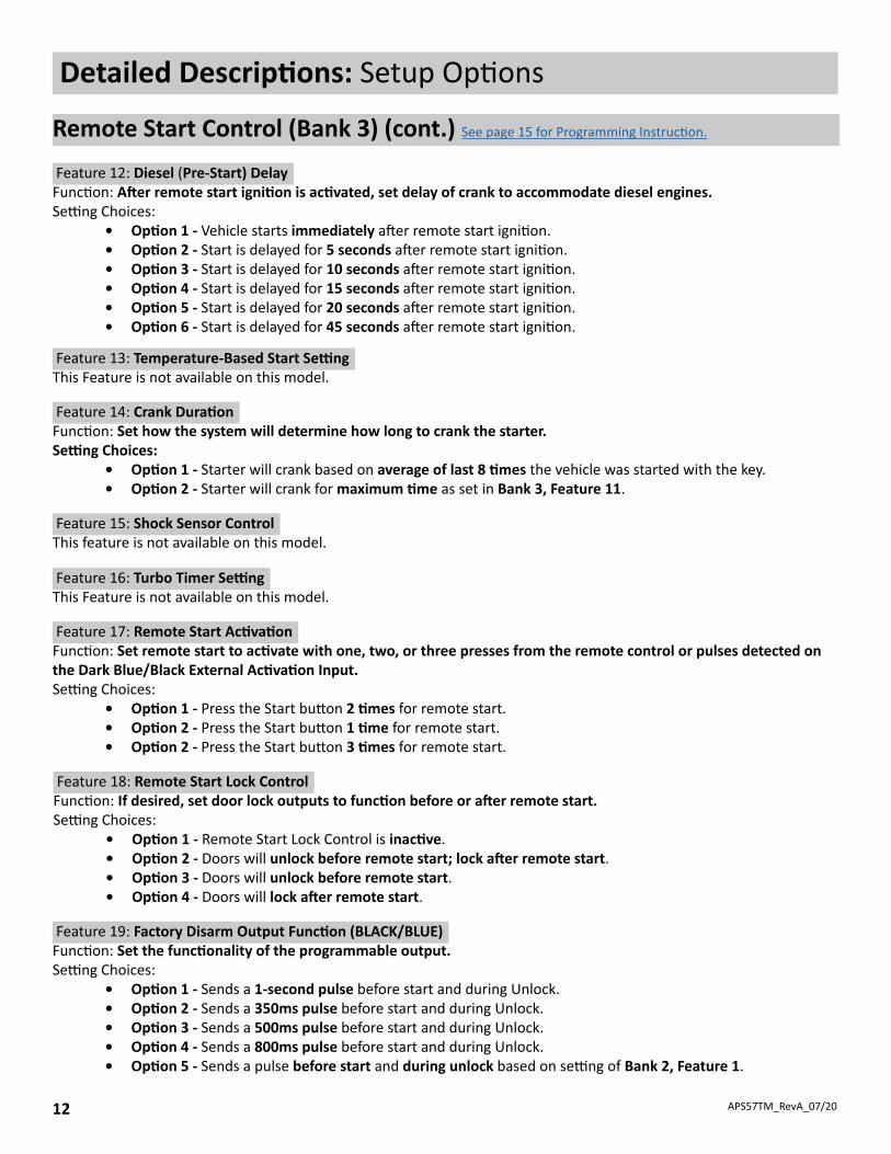
Feature 12: Diesel (Pre-Start) DelayFunction: After remote start ignition is activated, set delay of crank to accommodate diesel engines. Setting Choices:
• Option 1 - Vehicle starts immediately after remote start ignition.• Option 2 - Start is delayed for 5 seconds after remote start ignition.• Option 3 - Start is delayed for 10 seconds after remote start ignition.• Option 4 - Start is delayed for 15 seconds after remote start ignition.• Option 5 - Start is delayed for 20 seconds after remote start ignition.• Option 6 - Start is delayed for 45 seconds after remote start ignition.
Feature 13: Temperature-Based Start SettingThis Feature is not available on this model.
Feature 14: Crank Duration Function: Set how the system will determine how long to crank the starter. Setting Choices:
• Option 1 - Starter will crank based on average of last 8 times the vehicle was started with the key.• Option 2 - Starter will crank for maximum time as set in Bank 3, Feature 11.
Feature 15: Shock Sensor ControlThis feature is not available on this model.
Feature 16: Turbo Timer SettingThis Feature is not available on this model.
Feature 17: Remote Start ActivationFunction: Set remote start to activate with one, two, or three presses from the remote control or pulses detected on the Dark Blue/Black External Activation Input. Setting Choices:
• Option 1 - Press the Start button 2 times for remote start.• Option 2 - Press the Start button 1 time for remote start.• Option 2 - Press the Start button 3 times for remote start.
Feature 18: Remote Start Lock ControlFunction: If desired, set door lock outputs to function before or after remote start. Setting Choices:
• Option 1 - Remote Start Lock Control is inactive.• Option 2 - Doors will unlock before remote start; lock after remote start.• Option 3 - Doors will unlock before remote start.• Option 4 - Doors will lock after remote start.
Feature 19: Factory Disarm Output Function (BLACK/BLUE)Function: Set the functionality of the programmable output.Setting Choices:
• Option 1 - Sends a 1-second pulse before start and during Unlock.• Option 2 - Sends a 350ms pulse before start and during Unlock.• Option 3 - Sends a 500ms pulse before start and during Unlock.• Option 4 - Sends a 800ms pulse before start and during Unlock.• Option 5 - Sends a pulse before start and during unlock based on setting of Bank 2, Feature 1.
APS57TM_RevA_07/20 13
Detailed Descriptions: Setup Options
Remote Start Control (Bank 3) (Cont.) See page 15 for Programming Instruction.
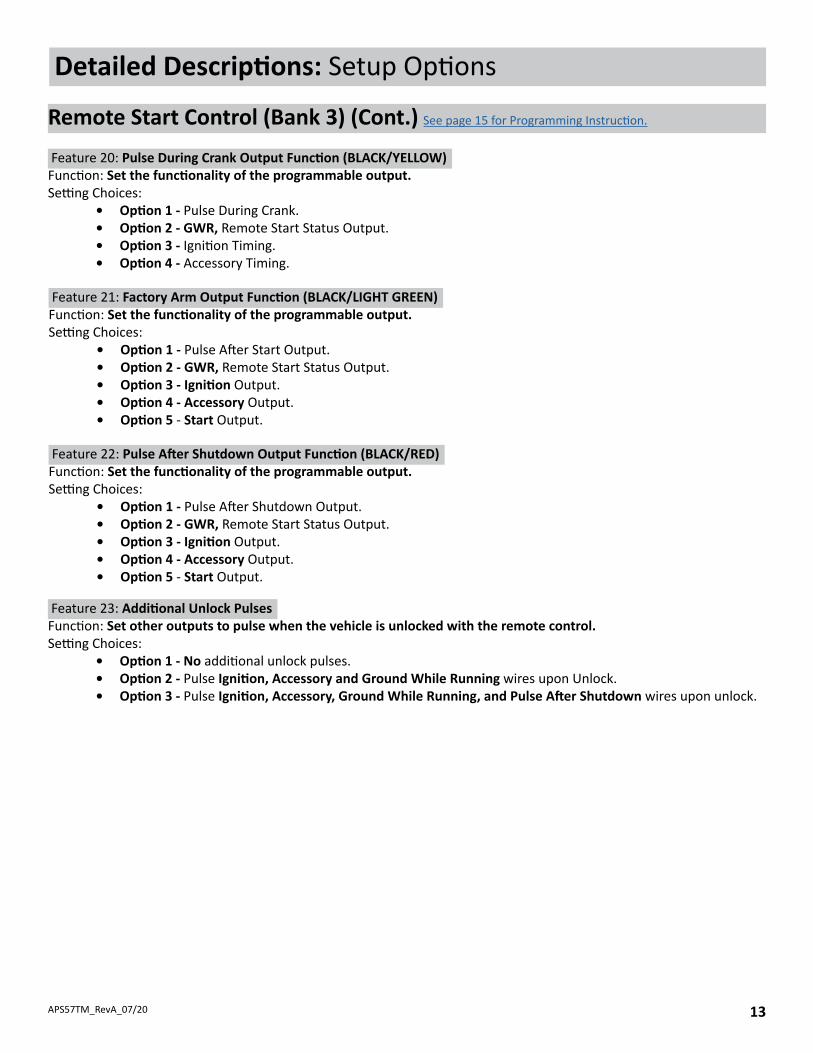
Feature 23: Additional Unlock PulsesFunction: Set other outputs to pulse when the vehicle is unlocked with the remote control. Setting Choices:
• Option 1 - No additional unlock pulses.• Option 2 - Pulse Ignition, Accessory and Ground While Running wires upon Unlock.• Option 3 - Pulse Ignition, Accessory, Ground While Running, and Pulse After Shutdown wires upon unlock.
Feature 20: Pulse During Crank Output Function (BLACK/YELLOW)Function: Set the functionality of the programmable output.Setting Choices:
• Option 1 - Pulse During Crank.• Option 2 - GWR, Remote Start Status Output.• Option 3 - Ignition Timing.• Option 4 - Accessory Timing.
Feature 21: Factory Arm Output Function (BLACK/LIGHT GREEN)Function: Set the functionality of the programmable output.Setting Choices:
• Option 1 - Pulse After Start Output.• Option 2 - GWR, Remote Start Status Output.• Option 3 - Ignition Output.• Option 4 - Accessory Output.• Option 5 - Start Output.
Feature 22: Pulse After Shutdown Output Function (BLACK/RED)Function: Set the functionality of the programmable output.Setting Choices:
• Option 1 - Pulse After Shutdown Output.• Option 2 - GWR, Remote Start Status Output.• Option 3 - Ignition Output.• Option 4 - Accessory Output.• Option 5 - Start Output.

APS57TM_RevA_07/2014
Three Button Remotes (1-Way)
Button Action FunctionPress 1x LockHold 3 Seconds Panic ON/OFFPress 1x UnlockHold 3 Seconds Panic ON/OFFPress 2x Start (Programable)Hold 3 Seconds Trunk ReleasePress 1xPress & HoldPress 1xPress & Hold
Programable AUX
Programable AUX
Detailed Descriptions: System Operation
Remote Control Operation
This system includes two (2) remote controls. The matrix below describes the basic functions of each remote. See Owners Guide for complete remote operation matrix.

APS57TM_RevA_07/20 15
2 = Bank 23 = Bank 3
Ignition On
Ignition O�
Press and ReleaseOverride Button
1 Chirp = Bank 1(Program Remotes)
Cycle Key to Advance Banks (2,3)
Chirps Indicate Bank Number
Chirps Indicate Option Number
Press Override Button to Advance Within Bank
Repeat Steps to Program Another Feature Bank...
... or Exit Programming
Press to Change Feature Option
LED IndicatesFeature Selection
3X
Note: Programming will time out after 60sec with no activity or Ignition Off for 5sec.
1X
Repeat Steps to Program Another Feature ...
LOCK
A
CC ON START
LOCK
A
CC ON START
LOCK
A
CC ON START
Once the system is installed and powered up, you will use the vehicle ignition, override button and a programmed remote control to set all system options. Feature options are divided into categories, or Banks, as described throughout this section. Ensure that at least one remote control is programmed to the system. If not, or if you need to program more remote controls, use the diagram steps to access Bank 1. The siren and LED will indicate your status and selections. Follow the diagram below to enter and maneuver through the programming procedure.
Quick Reference: System Programming
Programming Mode Entry and Exit Procedure
1. Turn the ignition ON.2. Press and release the valet button three (3) times.3. The system will beep (1) one time, indicating you have accessed Bank 1.4. Each cycle of the Ignition, OFF/ON, will advance to the next bank (up to Bank 3) then restart at Bank 2. (Note: To re-
access Bank 1 for transmitter programming, you will need to exit and re-enter programming mode.)5. The system will beep a number of times to indicate the Bank number:
• 1 beeps: Bank 1 - Programming Remote Controls• 2 beeps: Bank 2 - Keyless Control Options• 3 beeps: Bank 3 - Remote Start Control Options
6. Once you have accessed the desired bank, press the valet button to advance though the features. The LED will flash a number of times to indicate the feature, based on the charts that follow this section. The system will chip a number of times to indicate the Option programmed.
7. Once you have accessed the desired feature, press the LOCK button on the remote control to advance though the feature's setting options. The system will beep a number of times to indicate the Option setting, based on the charts that follow this section.
8. Once you have made the desired setting, you can press the valet button to advance through the features within the bank, or cycle the Ignition key OFF/ON to advance to the next bank.
9. Once you have completed programming, you MUST turn the ignition key to OFF to exit the programming mode. Programming will automatically exit after 60 seconds of inactivity.

APS57TM_RevA_07/2016
1 Chirp 2 Chirp 3 Chirp 4 chirp 5 Chirp 6 Chirp1 Defrost Output NA2 RS Start No�fica�on ON OFF3 RS Run�me 15min 20min 45min 60min 5min 10min4 RS Parking Lights Steady Flashing5 Engine Confirma�on Tach Voltage Data Hybrid6 Voltage Level >0.5v B4 Start <0.5v B4 Start7 Igni�on 2 Output Ignition Accessory Start8 Igni�on 3 Output N/A9 Accessory Output Accessory Igni�on Start
10 Transmission NA11 Max Crank Time 0.8sec 1.0sec 1.5sec 2.0sec 3.0sec 4.0sec12 Diesel Delay OFF Diesel 5 Diesel 10 Diesel 15 Diesel 20 Diesel 3013 Temperature Start NA14 Crank Dura�on Averaging Preset15 RS Shock Override NA16 Turbo Timer NA17 Start Ac�va�on Two Press One Press Three Press18 RS Lock Func�on No Change UL Before L A�er UL Before Start Lock A�er Start19 Factory Disarm Output Single Pulse 350ms 500ms 800ms Same As Bank 2, F120 Pulse During Crank During Crank GWR Igni�on Accessory21 Factory Arm Output After Start GWR Igni�on Accessory Start22 Pulse A�er Shutdown After Shutdown GWR Igni�on Accessory Start
23 Addi�onal Unlock Pulse No Pulse IGN, ACC, GWR IGN,ACC,GWR,PASD
Feat
ures
Feature Bank 3 Op�ons
Quick Reference: System Programming
Bank 1: Transmitter Programming Options See page 7 for a detailed description.
Bank 2: Keyless Options See pages 8-9 for detailed descriptions.
1 Chirp 2 Chirp 3 Chirp 4 Chirp 5 Chirp 6 Chirp1 Lock / Unlock Func�on 500ms 3.5sec 500ms L, DBL UL DBL L, 500ms UL DBL L, DBL UL 500ms L, 350ms UL2 Accessory Lock NA3 Accessory Unlock NA4 Exterior Il lumina�on NA5 Auto Relock NA6 Auto Arming NA7 No�fica�on Sound NA8 Horn Timing 16ms 30ms 40ms 50ms 10ms9 Valet Override Method NA
10 Driver Priority Unlock NA11 Silent Choice OFF From Transmi�er OEM Style12 Park Light / Trunk Swap NA13 AUX Ch. 4 NA14 AUX Ch. 5 NA15 AUX Ch. 6 NA16 AUX Ch. 7 NA17 Security Profi le OFF OEM Security W/ OEM Remote Start
18 Data Port Protocol ADS DBI
Feature Bank 2 Op�ons
Feat
ures
Bank 3: Remote Start Options See pages 10-13 for detailed descriptions.
1 Auto Program/Lock2 Unlock3 Trunk/Start
Feature Bank 1 Descrip�on
CH.
Press Lock bu�on on remotePress Unlock bu�on on remotePress Start bu�on on remote

APS57TM_RevA_07/20 17
Quick Reference: System Programming & Diagnostics
Tach Function
When using the GREEN/ORANGE tach wire, the vehicle tach rate must be programmed.
Programming with valet button when tach wire is connected:1. Turn the ignition key to the ON position.2. Press and release the valet button three (3) times.3. Immediately turn the ignition key OFF.4. Press and hold the valet button, then start the vehicle using the key.5. When the unit senses the tach signal, the parking lights will begin to flash.6. Allow the vehicle to settle to a normal idle speed.7. Release the valet button.
The parking lights will turn on for two (2) seconds and one (1) long chip will indicate that the learned tach signal is stored and the unit has exited tach learn mode.
Programming without valet button when tach wire is connected:1. Turn the ignition key to the ON position and start the vehicle's engine.2. Wait for Engine RPM to lower to a normal idle.3. Press and hold the vehicle's brake pedal.4. Press the LOCK button on the OEM remote or the Carlink App.
The vehicle's parking lights will flash seven (7) times to indicate the tach signal has been learned. If the parking lights do not flash, locate another tach source and repeat steps 1 - 4 above.
Note: Programming tach signal via OEM or Telematics control is only available on Firmware v1.47 or Higher.
Data Port Protocol Selection
The default data port protocol of this model is ADS (iDatalink 2-Way). This model is capable of detecting the correct data port protocol (ADS or DBI) and automatically configuring Feature Bank 2; Feature 18. To initialize the detection procedure:
1. Press and hold the valet button.2. Cycle the vehicle’s Ignition ON/OFF two (2) times.3. Release the valet button.
Note: This feature is only available on module firmware v2.00 or higher.
The Valet Override procedure will disable the alarm when the remote is not available or has become inoperative. If the vehicle door is opened without disarming, the alarm will sound and the vehicle will not start when attempting to start with the key. To disable the alarm:
1. Turn the vehicle ignition to ON.2. Within 5sec, press and release valet button one (1) time.
The alarm will silence and the vehicle will now start normally with the key.
Valet Alarm Override (Optional)

APS57TM_RevA_07/2018
Troubleshooting Remote Start
All Prestige remote start system will provide parking light feedback to display remote start errors or shutdowns. The vehicle parking lights will flash to display error or shutdown code.
1 Run�me Expired2 Remote Shutdown3 Brake On4 Manual Mode5 Hood Open6 Low / No Tach7 Tach Programming8 High Tach
Quick Reference: System Programming & Diagnostics
Silent Lock and Unlock
Program the Prestige system to Lock and Unlock without notification beeps.
1. Turn the ignition ON then OFF.2. Press and release the valet button three (3) times. The system will respond with one (1) beep for ON or two (2) beeps for OFF.
User Selectable LED
This feature will control whether the LED is ON or OFF when the system is Armed/Locked. This will be selectable in feature programming OR on-the-fly without entering the programming feature banks.
1. Turn the ignition ON, OFF, ON, OFF.2. Press and hold valet button for five (5) seconds.
The LED will flash one (1) time for ON, two (2) times for OFF. This feature will not affect LED flash during programming.
APS57TM_RevA_07/20 19
Quick Reference: Wiring Diagrams
Door Lock Connections
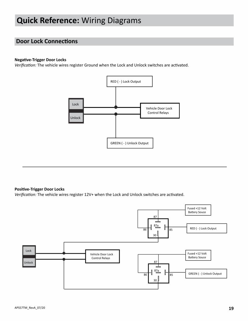
Positive-Trigger Door LocksVerification: The vehicle wires register 12V+ when the Lock and Unlock switches are activated.
Negative-Trigger Door LocksVerification: The vehicle wires register Ground when the Lock and Unlock switches are activated.
Lock
Unlock
Vehicle Door Lock Control Relays
RED ( - ) Lock Output
GREEN ( - ) Unlock Output
Lock
Unlock
87
87a86 85
30
87
87a86 85
30
Vehicle Door Lock Control Relays
Fused +12 Volt Battery Souce
Fused +12 Volt Battery Souce
RED ( - ) Lock Output
GREEN ( - ) Unlock Output
APS57TM_RevA_07/2020
Quick Reference: Wiring Diagrams
Door Lock Connections
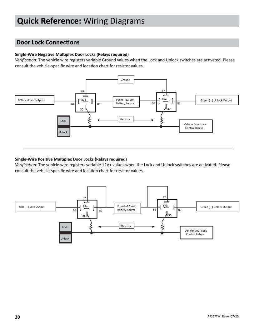
Single-Wire Negative Multiplex Door Locks (Relays required)Verification: The vehicle wire registers variable Ground values when the Lock and Unlock switches are activated. Please consult the vehicle-specific wire and location chart for resistor values.
Single-Wire Positive Multiplex Door Locks (Relays required)Verification: The vehicle wire registers variable 12V+ values when the Lock and Unlock switches are activated. Please consult the vehicle-specific wire and location chart for resistor values.
Lock
Unlock
Vehicle Door Lock Control Relays
RED ( - ) Lock Output Green ( - ) Unlock Output
87
87a86
30
87
87a86
30
85 85Fused +12 VoltBattery Source
Ground
Resistor
Lock
Unlock
Vehicle Door Lock Control Relays
RED ( - ) Lock Output Green ( - ) Unlock Output
87
87a86
30
87
87a86
30
85 85Fused +12 VoltBattery Source
Resistor

APS57TM_RevA_07/20 21
Quick Reference: Wiring Diagrams
Door Lock Connections
Reverse-Polarity Door Locks (Relays required)Verification: The vehicle wires rest at Ground and register 12V+ when the Lock and Unlock switches are activated.
Aftermarket Actuators (Relays and door lock actuators required)
Lock
Unlock
87
87a86 85
30
87
87a86 85
30
Fused +12 Volt Battery Souce
Fused +12 Volt Battery Souce
RED ( - ) Lock Output
Green ( - ) Unlock Output
XCut
XCut
To Door Lock Motor
To Door Lock Motor
30
87
87a
86 85
Fused +12 VoltBatter y Source
Door Lock Actuator
30
87
87a
86 85
ChassisGround
ChassisGround
RED ( - ) Lock Output
GREEN ( - ) Unlock Output
Fused +12 VoltBatter y Source
M

APS57TM_RevA_07/2022
Quick Reference: Wiring Diagrams
12
34
VOXX
FLCA
RT D
ock
1Ye
llow
Star
ter O
utpu
t (+)
2G
reen
Igni
on 2
Out
put (
+)3
Red
Baer
y 12
V In
put (
+)4
Red/
Whi
teBa
ery
12V
Inpu
t (+)
5Pu
rple
Acce
ssor
y O
utpu
t (+)
6Bl
ueIg
nion
Inpu
t / O
utpu
t (+)
6 Pin RS Harness
PP
1W
hite
Park
ing
Ligh
t (30
) Out
put
2W
hite
/Red
Park
ing
Ligh
t (87
) Inp
ut3
Yello
w/B
lack
Igni
tion
Out
put F
or A
larm
(+)
4Bl
ack
Gro
und
Inpu
t (-)
4 Pin Light
P
Repl
acem
ent P
art #
4120
463
Repl
acem
ent P
art #
4120
467
13
5
24
6
13
24
Repl
acem
ent P
art #
4120
465
Repl
acem
ent P
art #
4120
476
Acce
ssor
y So
ld S
eper
atly
Acce
ssor
y So
ld S
eper
atly
1234
19 17 15 13 11 9 7 5 3 124681012141618201 2 3 4
12
35791113
468101214
4Re
dBa
ery
12V
(+)
3Bl
ue
Dat
a TX
2Bl
ack
Grou
nd (-
)1
Whi
teD
ata
RX
DBI
4Re
dBa
ery
12V
(+)
3Bl
ue
Dat
a TX
2Bl
ack
Grou
nd (-
)1
Whi
teD
ata
RX
CarLink
This
Harn
ess i
s inc
lude
d w
ith th
e FL
CART
.
For W
ire In
form
a�on
and
Dia
gram
Ple
ase
Refe
r to
Vehi
cle
Spec
ific
Flas
hLog
ic In
stal
l Gui
de.
Visit
ww
w.F
lash
Logi
c.co
m fo
r Mor
e In
form
a�on
.
12
34
56
1Pi
nkBa
�er
y 5V
(+)
2G
reen
Dat
a RX
3Bl
ack
Gro
und
(-)
4Re
dV
alet
Sw
itch
5Bl
ueLE
D (-
)6
Empt
yEm
pty
Antenna
4R
edBa
ttery
12V
(+)
3Bl
ack
Gro
und
(-)2
Whi
teD
ata
RX
1Bl
ueD
ata
TX
Weblink
Acce
ssor
y So
ld S
eper
atly
Repl
acem
ent P
art #
4361
009
14G
reen
/Ora
nge
Tach
Inpu
t13
Blac
k/Ye
llow
Pulse
Dur
ing
Cran
k O
utpu
t (-)
12G
reen
/Yel
low
Glo
w P
lug
Inpu
t (+)
11Bl
ack/
Red
Pulse
Aer
Shu
tdow
n O
utpu
t (-)
10Dk
. Blu
eTr
unk
Out
put (
-)9
Blac
k/Bl
ueFa
ctor
y Di
sarm
Out
put (
-)8
Brow
n/Bl
ack
Brak
e In
put (
+)7
Blac
k/Lt
. Gre
enFa
ctor
y Ar
m O
utpu
t (-)
6Dk
. Blu
e/Bl
ack
Exte
rnal
Ac
vaon
Inpu
t (-)
5Lt
. Blu
eRe
mot
e St
art S
tatu
s O
utpu
t (-)
4G
reen
Unl
ock
Out
put (
-)3
Gra
y/Bl
ack
Hood
Inpu
t (-)
2Re
dLo
ck O
utpu
t (-)
1Bl
ack/
Whi
teHo
rn O
utpu
t (-)
14 Pin Main Input/Output
183B
P18
3BP
4180
070