Embed Size (px)
Citation preview
Automation Consulting Services, Inc.
APS
AutoMate® Programming System
User's Manual
Revision 1.15 --- May 26, 2003
Software Revision: 1.0g
Copyright © 1992-2003 Automation Consulting Services, Inc. All rights reserved. Subject to change without notice.
Automation Consulting Services, Inc.
78 Jones Road—P. O. Box 17 Hopedale, MA 01747 Voice: (508) 473-9079 Fax: (508) 473-3543
DANGER
ONLY QUALIFIED ELECTRICAL PERSONNEL FAMILIAR WITH THE CONSTRUCTION AND OPERATION OF THIS EQUIPMENT AND THE HAZARDS INVOLVED SHOULD INSTALL, ADJUST, OPERATE, AND/OR SERVICE IT. READ AND UNDERSTAND THE APPLICABLE MANUALS IN THEIR ENTIRETY BEFORE PROCEEDING. FAILURE TO OBSERVE THESE PRECAUTIONS COULD RESULT IN SEVERE BODILY INJURY OR LOSS OF LIFE.
WARNING
RELIANCE STRONGLY RECOMMENDS THE USE OF AN EXTERNAL, HARDWIRED EMERGENCY STOP CIRCUIT THAT WILL DISABLE THE SYSTEM IN CASE OF IMPROPER OPERATION. UNCONTROLLED MACHINE OPERATION MAY RESULT IF THIS PROCEDURE IS NOT FOLLOWED. FAILURE TO OBSERVE THIS PRECAUTION COULD RESULT IN BODILY INJURY.
R-Net™, APX™, and ReSource™ are trademarks of Reliance Electric Company or its subsidiaries. Reliance® and AutoMate® are trademarks of Reliance Electric Company or its subsidiaries. i486™ and MultiBus™ are trademarks of Intel Corporation. MS-DOS™ and Windows™ are trademarks of Microsoft Corporation. BTrieve™ is a trademark of Novell, Inc. UpDoc™ is a trademark of Xcel, Inc. LaserJet™ is a trademark of Hewlett-Packard Co. Hercules® is a trademark of Hercules Computer Technology. IBM®-PC/XT/AT/PS2 are trademarks of International Business Machines Corp. Toshiba™ is a trademark of Toshiba America. QEMM-386™ is a trademark of Quarterdeck Office Systems. 386^MAX™ is a trademark of Qualitas, Inc. Other trademarks remain the property of their respective holders. APS was created for Reliance Electric by:
Automation Consulting Services, Inc. P. O. Box 17
Hopedale, MA 01747
i
Table of Contents
1. Introduction ..................................................................................................................1-1
1.1. DOS.......................................................................................................................1-1
1.2. Memory .................................................................................................................1-1 Conventional Memory..............................................................................1-1 Expanded (LIM / EMS) Memory .............................................................1-1
1.3. Mouse ....................................................................................................................1-2
1.4. APS and Windows..................................................................................................1-2
1.5. Copy Protection .....................................................................................................1-2
1.6. Sample Files ...........................................................................................................1-3
1.7. Help .......................................................................................................................1-3
1.8. Emergency Exit ......................................................................................................1-3
1.9. Additional Information ...........................................................................................1-3
2. Manual Conventions.....................................................................................................2-1
2.1. Typographical Conventions ....................................................................................2-1
2.2. The Mouse .............................................................................................................2-1
2.3. Dialog Box Fields...................................................................................................2-1
3. Installing APS ...............................................................................................................3-1
3.1. Install To................................................................................................................3-1
3.2. Modify CONFIG.SYS ................................................................................................3-2
3.3. Install Template Files..............................................................................................3-2
3.4. Install Sample Files.................................................................................................3-3
3.5. Temporary Files On…............................................................................................3-3
3.6. Install LaserJet Fonts..............................................................................................3-3
4. Working with APS ........................................................................................................4-1
4.1. Starting APS ..........................................................................................................4-1
4.2. Using The Menus ...................................................................................................4-2 Menu Highlight ........................................................................................4-2 Shortcut Keys ..........................................................................................4-3 Using the Mouse ......................................................................................4-3 Dialog Boxes ...........................................................................................4-3
4.3. The “No File” Menu ...............................................................................................4-3 4.3.1. Maintain Backups… ...................................................................................4-4
ii
4.4. Opening A Program ...............................................................................................4-4 Changing the Path....................................................................................4-5 Opening the Sample File ..........................................................................4-6
4.5. The Sequence Editor..............................................................................................4-6
4.6. The Select Menu ....................................................................................................4-6
4.7. Point and Register Descriptions..............................................................................4-7 4.7.1. Defining Points...........................................................................................4-8 4.7.2. Defining Registers ......................................................................................4-8 4.7.3. Adding Sequence Descriptions....................................................................4-8 4.7.4. Printing the Documented Ladder Listing.....................................................4-9 4.7.5. Configuring ................................................................................................4-9
4.8. Going Online..........................................................................................................4-9
4.9. Monitoring.............................................................................................................4-9
4.10. Other Features .......................................................................................................4-9
4.11. Compatibility With APX ........................................................................................4-10
4.12. Leaving APS..........................................................................................................4-10
4.13. Starting With an Existing AutoMate Application ....................................................4-10 4.13.1. Editing a Program Currently Located in an AutoMate Processor.................4-10 4.13.2. Editing a Program Created with APX .........................................................4-10 4.13.3. Editing a Program Created with ACS Products...........................................4-10
4.14. Manual Structure ...................................................................................................4-11
5. The APS Keyboard.......................................................................................................5-1
5.1. Help.......................................................................................................................5-1 Multiple-Topic Help ................................................................................5-1 Help Index...............................................................................................5-1
5.2. Cancel....................................................................................................................5-1
5.3. Confirmation Boxes ...............................................................................................5-2
5.4. Menu Keys.............................................................................................................5-2
5.5. Global Function Keys.............................................................................................5-3
5.6. Dialog Box Keys....................................................................................................5-3 5.6.1. Moving the Highlight..................................................................................5-3 5.6.2. Replacing a Value.......................................................................................5-4 5.6.3. Editing a Value...........................................................................................5-4 5.6.4. Non-Text Fields..........................................................................................5-4
Boolean (Yes / No) Fields........................................................................5-5 List Select Fields......................................................................................5-5 Value List Fields......................................................................................5-6 Buttons....................................................................................................5-6
5.6.5. Accepting Dialog Values ............................................................................5-6
6. The File Menu...............................................................................................................6-1
iii
6.1. New… ...................................................................................................................6-1
6.2. Open… ..................................................................................................................6-2 Changing the Path and Filter ....................................................................6-2
6.3. Save .......................................................................................................................6-3 Backup Version .......................................................................................6-3
6.4. Save As… ..............................................................................................................6-4
6.5. Restore...................................................................................................................6-4
6.6. Save / Load APX…................................................................................................6-4
6.7. Download (To)…...................................................................................................6-4 GOTO Checks............................................................................................6-5 20000 Register Checks.............................................................................6-5
6.8. Upload (From) .......................................................................................................6-5
6.9. Go Online…...........................................................................................................6-5 Direct Connection....................................................................................6-5 Gateway Communications........................................................................6-6 The R-Net PC Link ..................................................................................6-6 Force Online ............................................................................................6-6
6.10. Go Offline ..............................................................................................................6-6
6.11. Exit ........................................................................................................................6-7
6.12. About….................................................................................................................6-7
7. The Utility Menu...........................................................................................................7-1
7.1. Control Window.....................................................................................................7-1 7.1.1. Cancel Access.............................................................................................7-2 7.1.2. Clear Forcing Tables ...................................................................................7-2 7.1.3. Force Inputs................................................................................................7-2 7.1.4. Force Outputs.............................................................................................7-3 7.1.5. Monitor / Modify........................................................................................7-4 7.1.6. Request Privileged Access...........................................................................7-5 7.1.7. Run Processor.............................................................................................7-5 7.1.8. Stop Processor............................................................................................7-6
7.2. Single Scan.............................................................................................................7-6
7.3. Printer Configuration..............................................................................................7-6
7.4. User Printer Configuration......................................................................................7-8 7.4.1. Set Page Length..........................................................................................7-9 7.4.2. Printer Strings.............................................................................................7-9 7.4.3. Save Changes..............................................................................................7-11
7.5. Communications Configuration...............................................................................7-11 7.5.1. Serial Mode ................................................................................................7-11 7.5.2. R-Net PC Link Operation ...........................................................................7-12
7.6. Monochrome Palette ..............................................................................................7-14 Forcing Monochrome Mode.....................................................................7-14
iv
Forcing Color Mode ................................................................................7-15
7.7. Send ASCII…........................................................................................................7-15
7.8. Send Binary…........................................................................................................7-15
7.9. Communications Addresses....................................................................................7-17
7.10. Register Limit… ....................................................................................................7-18
7.11. Auxiliary… ............................................................................................................7-19 7.11.1. Clear Memory ............................................................................................7-19 7.11.2. Request Privileged Access ..........................................................................7-19 7.11.3. Cancel Privileged Access ............................................................................7-20 7.11.4. Protect Memory (A15) ...............................................................................7-20 7.11.5. Access via Port 1 (A15)..............................................................................7-20 7.11.6. Access via R-Net (A15)..............................................................................7-20 7.11.7. I/O Port Diagnostic (A15) ..........................................................................7-20 7.11.8. Set Gateway Parameters .............................................................................7-20 7.11.9. Global Set Max Nodes................................................................................7-21
7.12. Convert..................................................................................................................7-21 Converting A15 Programs .......................................................................7-22
7.13. Rebuild Database ...................................................................................................7-22
8. Document Point / Register Descriptions ......................................................................8-1
8.1. Introduction...........................................................................................................8-1 8.1.1. Screen Types..............................................................................................8-1
Register Definitions .................................................................................8-1 Digital I/O Descriptions ...........................................................................8-2 Internal Relay Definitions.........................................................................8-5
8.1.2. Basic Point / Register Description Editor Operation....................................8-5 8.1.3. Shortcut Keys.............................................................................................8-6
8.2. The File Menu........................................................................................................8-6
8.3. The Select Menu ....................................................................................................8-6
8.4. The Edit Menu.......................................................................................................8-6 8.4.1. Cut .............................................................................................................8-6 8.4.2. Delete.........................................................................................................8-6 8.4.3. Paste ..........................................................................................................8-7 8.4.4. Change… ...................................................................................................8-7 8.4.5. Copy ..........................................................................................................8-8 8.4.6. Restore.......................................................................................................8-8 8.4.7. Copy / Move Descriptions ..........................................................................8-8 8.4.8. Erase Descriptions......................................................................................8-10 8.4.9. Purge Descriptions .....................................................................................8-10 8.4.10. Edit Block Title ..........................................................................................8-10 8.4.11. Import ASCII .............................................................................................8-11 8.4.12. Export ASCII .............................................................................................8-13
Comma-Delimited Export / Import Format ..............................................8-14
v
8.5. The Locate Menu ...................................................................................................8-14 8.5.1. First ............................................................................................................8-15 8.5.2. Previous......................................................................................................8-15 8.5.3. Next ...........................................................................................................8-15 8.5.4. Last ............................................................................................................8-15 8.5.5. Goto ...........................................................................................................8-15
8.6. The Print Menu ......................................................................................................8-15 8.6.1. Ladder / Xref… ..........................................................................................8-15
Setup .......................................................................................................8-16 The Documented Listing ..........................................................................8-17
8.6.2. Name Index ................................................................................................8-19 8.6.3. Point / Register List ....................................................................................8-19 8.6.4. Hardware List .............................................................................................8-19 8.6.5. Card List.....................................................................................................8-19 8.6.6. Align Tags ..................................................................................................8-19 8.6.7. Wire Tags… ...............................................................................................8-20 8.6.8. Print Multiple…..........................................................................................8-20 8.6.9. Top of Form ...............................................................................................8-21
8.7. The Utility Menu ....................................................................................................8-21
8.8. The AutoGen Menu................................................................................................8-21 8.8.1. Add Point Descriptions ...............................................................................8-21 8.8.2. Create Register Descriptions .......................................................................8-22 8.8.3. Erase Register Descriptions.........................................................................8-23
8.9. The Card Lists........................................................................................................8-23 Editing Card Definitions...........................................................................8-23 Printing Card Definitions..........................................................................8-24
9. Document Sequence Descriptions.................................................................................9-1
9.1. Introduction ...........................................................................................................9-1 9.1.1. Description Types .......................................................................................9-1 9.1.2. Editing Section and Line Comments............................................................9-2 9.1.3. Editing Text Comments ..............................................................................9-2 9.1.4. Shortcut Keys .............................................................................................9-2
9.2. The File Menu ........................................................................................................9-3
9.3. The Select Menu ....................................................................................................9-3
9.4. The Edit Menu .......................................................................................................9-3 9.4.1. Cut .............................................................................................................9-3 9.4.2. Delete .........................................................................................................9-3 9.4.3. Paste...........................................................................................................9-3 9.4.4. Change…....................................................................................................9-3 9.4.5. Copy...........................................................................................................9-4 9.4.6. Restore .......................................................................................................9-4 9.4.7. Copy / Move Descriptions...........................................................................9-4 9.4.8. Erase Descriptions ......................................................................................9-4 9.4.9. Import ASCII .............................................................................................9-4 9.4.10. Export ASCII .............................................................................................9-4
vi
9.5. The Locate Menu...................................................................................................9-4 9.5.1. Previous .....................................................................................................9-4 9.5.2. Next ...........................................................................................................9-4 9.5.3. Goto...........................................................................................................9-5
9.6. The Print Menu......................................................................................................9-5
9.7. The Utility Menu....................................................................................................9-5
10. Document Title Descriptions........................................................................................10-1
11. Document Racks ...........................................................................................................11-1
11.1. Introduction...........................................................................................................11-1 11.1.1. Rack Fields.................................................................................................11-1 11.1.2. Shortcut Keys.............................................................................................11-2
11.2. The File Menu........................................................................................................11-2
11.3. The Select Menu ....................................................................................................11-3
11.4. The Edit Menu.......................................................................................................11-3 11.4.1. Cut .............................................................................................................11-3 11.4.2. Delete.........................................................................................................11-3 11.4.3. Paste ..........................................................................................................11-3 11.4.4. Change… ...................................................................................................11-3 11.4.5. Copy ..........................................................................................................11-3 11.4.6. Restore.......................................................................................................11-3 11.4.7. Add Rack… ...............................................................................................11-4 11.4.8. Copy Rack…..............................................................................................11-4 11.4.9. Erase Rack .................................................................................................11-4
11.5. The Locate Menu...................................................................................................11-4 11.5.1. Previous .....................................................................................................11-4 11.5.2. Next ...........................................................................................................11-4 11.5.3. Goto...........................................................................................................11-5
11.6. The Print Menu......................................................................................................11-5 11.6.1. Racks… .....................................................................................................11-5 11.6.2. Card List ....................................................................................................11-5 11.6.3. Print Multiple… .........................................................................................11-5 11.6.4. Top of Form...............................................................................................11-5
12. The Sequence Editor ....................................................................................................12-1
12.1. Introduction...........................................................................................................12-2 12.1.1. Initial Screen Display..................................................................................12-2 12.1.2. Basic Sequence Editor Operation................................................................12-2 12.1.3. Editing Sequences Online ...........................................................................12-3
Updating Sequences Online .....................................................................12-4 12.1.4. Uploading an Existing Application Program................................................12-4
“Recompiling” an Existing Program.........................................................12-5 12.1.5. Shortcut Keys.............................................................................................12-5
vii
Locating Keys:.........................................................................................12-5 Editing Keys: ...........................................................................................12-5
12.2. The File Menu ........................................................................................................12-6
12.3. The Select Menu ....................................................................................................12-6
12.4. The Edit Menu .......................................................................................................12-6 12.4.1. Circuit / Function Block..............................................................................12-6
Memory Addresses ..................................................................................12-6 Constants.................................................................................................12-7 Values......................................................................................................12-7 Slot / Channel ..........................................................................................12-7 GOTO and GOSUB Addresses......................................................................12-7 Elapsed Registers.....................................................................................12-7 PRINT Texts ..............................................................................................12-8 Quick Define............................................................................................12-8
12.4.2. Coil….........................................................................................................12-8 12.4.3. Contact .......................................................................................................12-9 12.4.4. Tie..............................................................................................................12-9 12.4.5. Expand… ...................................................................................................12-9
12.4.5.1. Insert Row (Vertical Expand) ....................................................12-10 12.4.5.2. Insert Column (Horizontal Expand) ...........................................12-10
12.4.6. Cut… .........................................................................................................12-10 12.4.7. Delete… .....................................................................................................12-11 12.4.8. Paste...........................................................................................................12-11 12.4.9. Change…....................................................................................................12-11
Find fields ................................................................................................12-12 Replace Fields..........................................................................................12-12 Sequence Range Fields.............................................................................12-13 Example...................................................................................................12-13
12.4.10. Copy…....................................................................................................12-14 Translate by Names..................................................................................12-15
12.4.11. Restore ....................................................................................................12-16 12.4.12. New Rung…............................................................................................12-16
Special Coils ............................................................................................12-17 12.4.13. DRUM Table ...........................................................................................12-17 12.4.14. Macro ......................................................................................................12-17
12.5. The Locate Menu ...................................................................................................12-17 12.5.1. Search….....................................................................................................12-17
The Search Criterion ................................................................................12-17 Setting A New Search Criterion ...............................................................12-18
12.5.2. Top.............................................................................................................12-18 12.5.3. Previous......................................................................................................12-19 12.5.4. Next ...........................................................................................................12-19 12.5.5. Bottom .......................................................................................................12-19 12.5.6. Goto… .......................................................................................................12-19 12.5.7. Xref… ........................................................................................................12-20 12.5.8. Quick Define…...........................................................................................12-21
Selecting The Quick Define Address ........................................................12-23 12.5.9. Monitor ......................................................................................................12-23
viii
12.6. The Print Menu......................................................................................................12-23 12.6.1. Quick Listing..............................................................................................12-23 12.6.2. Register Values ..........................................................................................12-24 12.6.3. Register Usage ...........................................................................................12-24 12.6.4. Coil Usage..................................................................................................12-25 12.6.5. Print Multiple… .........................................................................................12-25 12.6.6. Top of Form...............................................................................................12-25
12.7. The Utility Menu....................................................................................................12-25
13. Macro Mode .................................................................................................................13-1
13.1. Introduction...........................................................................................................13-1 13.1.1. Entering The Macro Subsection..................................................................13-1 13.1.2. Creating Macros.........................................................................................13-1 13.1.3. Constants and Variables..............................................................................13-2 13.1.4. Executing Macros.......................................................................................13-3 13.1.5. Shortcut Keys.............................................................................................13-3
Locating Keys: ........................................................................................13-3 Editing Keys: ...........................................................................................13-3
13.2. Return....................................................................................................................13-4
13.3. Macro ....................................................................................................................13-4 13.3.1. New ...........................................................................................................13-4 13.3.2. Open… ......................................................................................................13-4 13.3.3. Save ...........................................................................................................13-4 13.3.4. Save As… ..................................................................................................13-5 13.3.5. Variable Prompts…....................................................................................13-5 13.3.6. Print… .......................................................................................................13-6 13.3.7. Execute ......................................................................................................13-6
13.4. Edit........................................................................................................................13-6 13.4.1. Circuit / Function Block .............................................................................13-6 13.4.2. Coil… ........................................................................................................13-7 13.4.3. Contact ......................................................................................................13-7 13.4.4. Tie..............................................................................................................13-8 13.4.5. Delete….....................................................................................................13-8 13.4.6. Restore.......................................................................................................13-8 13.4.7. New Rung… ..............................................................................................13-9
13.5. Locate....................................................................................................................13-9 13.5.1. Top ............................................................................................................13-9 13.5.2. Previous .....................................................................................................13-9 13.5.3. Next ...........................................................................................................13-9 13.5.4. Bottom.......................................................................................................13-9 13.5.5. Goto….......................................................................................................13-10
14. The Drum Table Editor / Monitor...............................................................................14-1
14.1. Introduction...........................................................................................................14-1 14.1.1. The Bit Display...........................................................................................14-1
ix
14.1.2. The Step Records .......................................................................................14-2 14.1.3. Working With The Mouse...........................................................................14-2 14.1.4. Shortcut Keys .............................................................................................14-2
14.2. Return....................................................................................................................14-3
14.3. The Edit Menu .......................................................................................................14-3 14.3.1. Delete… .....................................................................................................14-3 14.3.2. Paste...........................................................................................................14-3 14.3.3. Change…....................................................................................................14-4 14.3.4. Copy...........................................................................................................14-4 14.3.5. Revert.........................................................................................................14-4 14.3.6. Insert… ......................................................................................................14-4 14.3.7. Event… ......................................................................................................14-4 14.3.8. Time… .......................................................................................................14-5 14.3.9. Goto… .......................................................................................................14-5 14.3.10. Decimal Mode..........................................................................................14-5 14.3.11. Monitor ...................................................................................................14-5 14.3.12. Quick Define…........................................................................................14-6
15. The Sequence Monitor..................................................................................................15-1
15.1. Introduction ...........................................................................................................15-1 15.1.1. Numeric Monitors.......................................................................................15-2 15.1.2. Looking Up Contacts..................................................................................15-2 15.1.3. Shortcut Keys .............................................................................................15-2
15.2. The File Menu ........................................................................................................15-3
15.3. The Select Menu ....................................................................................................15-3
15.4. The Locate Menu ...................................................................................................15-3 15.4.1. Quick Page n ..............................................................................................15-3 15.4.2. Define Quick Page… ..................................................................................15-4 15.4.3. Top.............................................................................................................15-4 15.4.4. Previous......................................................................................................15-4 15.4.5. Goto… .......................................................................................................15-4 15.4.6. Next ...........................................................................................................15-4 15.4.7. Bottom .......................................................................................................15-4 15.4.8. Quick Define...............................................................................................15-5
15.5. The Monitor Menu .................................................................................................15-5 15.5.1. Add Sequence….........................................................................................15-5 15.5.2. Remove Sequence…...................................................................................15-5 15.5.3. Load Page...................................................................................................15-5 15.5.4. Save Page ...................................................................................................15-5 15.5.5. Add Numeric Monitor….............................................................................15-5 15.5.6. Remove Numeric Monitor….......................................................................15-6 15.5.7. Drum Monitor ............................................................................................15-7 15.5.8. PID Monitor ...............................................................................................15-7
15.6. The Utility Menu ....................................................................................................15-8
16. The Register Monitor....................................................................................................16-1
x
16.1. Introduction...........................................................................................................16-1 16.1.1. Register Monitor Symbols ..........................................................................16-2 16.1.2. Using the Highlight.....................................................................................16-3 16.1.3. Shortcut Keys.............................................................................................16-3
16.2. The File Menu........................................................................................................16-4
16.3. The Select Menu ....................................................................................................16-4
16.4. The Monitor Menu.................................................................................................16-4 16.4.1. Add… ........................................................................................................16-4 16.4.2. Blank…......................................................................................................16-6 16.4.3. Clear….......................................................................................................16-6
16.4.3.1. Registers and Points ..................................................................16-6 16.4.3.2. Forced Points ............................................................................16-6 16.4.3.3. Both..........................................................................................16-7
16.4.4. Label… ......................................................................................................16-7 16.4.5. Load Page… ..............................................................................................16-7 16.4.6. Save Page…...............................................................................................16-8 16.4.7. Modify…....................................................................................................16-9
Next and Previous Registers ....................................................................16-10 16.4.8. Copy… ......................................................................................................16-10 16.4.9. Force Inputs… ...........................................................................................16-11 16.4.10. Force Outputs…......................................................................................16-12 16.4.11. Monitor ...................................................................................................16-12 16.4.12. String Monitor.........................................................................................16-13
16.5. The Utility Menu....................................................................................................16-13
16.6. The String Monitor ................................................................................................16-13 16.6.1. Introduction ...............................................................................................16-13 16.6.2. Shortcut Keys.............................................................................................16-13 16.6.3. Return ........................................................................................................16-14 16.6.4. Monitor ......................................................................................................16-14
16.6.4.1. Add….......................................................................................16-14 16.6.4.2. Clear .........................................................................................16-14 16.6.4.3. Remove.....................................................................................16-14 16.6.4.4. Shift Left...................................................................................16-14 16.6.4.5. Shift Right.................................................................................16-15 16.6.4.6. Edit….......................................................................................16-15 16.6.4.7. Monitor.....................................................................................16-15
16.7. The String Editor ...................................................................................................16-15 16.7.1. Introduction ...............................................................................................16-15
String Editor Cursors...............................................................................16-16 Changing String Bytes .............................................................................16-16
16.7.2. Shortcut Keys.............................................................................................16-17 16.7.3. Return ........................................................................................................16-17 16.7.4. Edit ............................................................................................................16-17
16.7.4.1. Insert ........................................................................................16-17 16.7.4.2. Delete .......................................................................................16-17 16.7.4.3. Code… .....................................................................................16-17
xi
16.7.4.4. Monitor .....................................................................................16-18
17. The Trend Line Monitor ..............................................................................................17-1
17.1. Introduction ...........................................................................................................17-1 17.1.1. Shortcut Keys .............................................................................................17-2
17.2. The Setup Dialog Box ............................................................................................17-2 17.2.1. The Sample Interval....................................................................................17-2 17.2.2. The Trace Setup Fields ...............................................................................17-2 17.2.3. The Watch List ...........................................................................................17-3
17.3. The File Menu ........................................................................................................17-4
17.4. The Select Menu ....................................................................................................17-4
17.5. The Edit Menu .......................................................................................................17-4 17.5.1. Load Page…...............................................................................................17-4 17.5.2. Save Page… ...............................................................................................17-4 17.5.3. Run.............................................................................................................17-4
17.6. The Utility Menu ....................................................................................................17-4
18. Diagnostics ....................................................................................................................18-1
18.1. Introduction ...........................................................................................................18-1 18.1.1. Shortcut Keys .............................................................................................18-1
18.2. The File Menu ........................................................................................................18-2
18.3. The Select Menu ....................................................................................................18-2
18.4. The Test Menu .......................................................................................................18-2 18.4.1. R-Net Test..................................................................................................18-2 18.4.2. RIOP Test ..................................................................................................18-2 18.4.3. R-Net PC Node Map ..................................................................................18-3 18.4.4. R-Net PC Status .........................................................................................18-4 18.4.5. Memory Diagnostic.....................................................................................18-5 18.4.6. Gateway Diagnostic ....................................................................................18-5
18.5. The Modify Menu...................................................................................................18-5 18.5.1. Clear Stops .................................................................................................18-5 18.5.2. Reset Max Scan ..........................................................................................18-5 18.5.3. Set Time… .................................................................................................18-6 18.5.4. R-Net PC Globals .......................................................................................18-6
18.6. The Utility Menu ....................................................................................................18-7
19. History Mode ................................................................................................................19-1
19.1. Introduction ...........................................................................................................19-1 19.1.1. Shortcut Keys .............................................................................................19-1
19.2. The File Menu ........................................................................................................19-1
19.3. The Select Menu ....................................................................................................19-1
19.4. The Record Menu...................................................................................................19-2
xii
19.4.1. Start Recorder ............................................................................................19-2 19.4.2. Stop Recorder ............................................................................................19-2 19.4.3. Configure… ...............................................................................................19-2 19.4.4. Load Page… ..............................................................................................19-4 19.4.5. Save Page…...............................................................................................19-4
19.5. The Playback Menu................................................................................................19-4 19.5.1. File… .........................................................................................................19-4 19.5.2. Stop Playback.............................................................................................19-5
19.6. The Report Menu...................................................................................................19-5 19.6.1. Configure Report…....................................................................................19-5 19.6.2. Print Report…............................................................................................19-7
Printed Reports........................................................................................19-7 Export Reports ........................................................................................19-7
19.6.3. Load Report Configuration….....................................................................19-7 19.6.4. Save Report Configuration… .....................................................................19-7
19.7. The Utility Menu....................................................................................................19-7
19.8. Adding Registers from Monitor Displays................................................................19-8 Adding Registers .....................................................................................19-8 Removing Registers.................................................................................19-8
19.9. History Playback Mode ..........................................................................................19-8 History Playback Shortcut Keys...............................................................19-9 History Menu Commands ........................................................................19-9
19.9.1. Pass............................................................................................................19-9 19.9.2. Move Window............................................................................................19-10 19.9.3. Goto….......................................................................................................19-10 19.9.4. Previous Record .........................................................................................19-10 19.9.5. Next Record...............................................................................................19-10 19.9.6. Increase Step..............................................................................................19-10 19.9.7. Decrease Step.............................................................................................19-11 19.9.8. Play Reverse...............................................................................................19-11 19.9.9. Play Forward..............................................................................................19-11 19.9.10. Help ........................................................................................................19-11
20. I/O Port Configuration (A20).......................................................................................20-1
20.1. Introduction...........................................................................................................20-1
20.2. A20 I/O Port Configuration Fields..........................................................................20-1
20.3. Updating the Configuration....................................................................................20-2
21. I/O Port Configuration (A30 / A40) .............................................................................21-1
21.1. Introduction...........................................................................................................21-1 21.1.1. Configuration Errors...................................................................................21-1 21.1.2. Shortcut Keys.............................................................................................21-2
21.2. The File Menu........................................................................................................21-2
21.3. The Select Menu ....................................................................................................21-2
xiii
21.4. The Edit Menu .......................................................................................................21-2 21.4.1. Clear...........................................................................................................21-2 21.4.2. Change…....................................................................................................21-3 21.4.3. Restore .......................................................................................................21-4 21.4.4. Insert Record… ..........................................................................................21-5 21.4.5. Delete Record.............................................................................................21-5 21.4.6. Print Table ..................................................................................................21-5 21.4.7. Update Table ..............................................................................................21-5
21.5. The Utility Menu ....................................................................................................21-5
Appendices
A. Files Used by APS .........................................................................................................A
A.1. APS Program Files .................................................................................................A-1
A.2. User Data Files.......................................................................................................A-1
B. Using APS with Microsoft Windows............................................................................B
B.1. PIF Settings............................................................................................................B-1 386 Enhanced Mode ................................................................................B-1 Standard Mode ........................................................................................B-2
C. Troubleshooting ............................................................................................................C
C.1. CONFIG.SYS ............................................................................................................C-1
C.2. The MODE Command..............................................................................................C-1
C.3. Resident (TSR) Programs.......................................................................................C-1
C.4. Video Problems......................................................................................................C-1
C.5. APS “Freezes” While Scrolling Through Program Online .......................................C-2
C.6. ANSI.SYS.................................................................................................................C-2
C.7. Hardware Key Not Found ......................................................................................C-2
C.8. Cannot Go Online...................................................................................................C-2
D. APS Errors ....................................................................................................................D
D.1. Communication Errors ...........................................................................................D-1
D.2. BTrieve Errors .......................................................................................................D-1
D.3. Virtual Memory Errors ...........................................................................................D-2
D.4. Memory Problems ..................................................................................................D-3
E. APS Glossary.................................................................................................................E

1-1
1. Introduction The products described in this instruction manual are manufactured and/or distributed by Reliance® Electric Industrial Company.
The AutoMate Programming System is a versatile software package designed to provide advanced AutoMate programming and documenting capabilities. It should run on any IBM PC/XT/AT/PS2 or compatible having 640K or more of memory, DOS 3.11 or later, and a serial communications card.
The Introduction section contains general information that you may find useful. Please read this section carefully before trying to use APS.
1.1. DOS
APS will operate under MS-DOS or PC-DOS Version 3.11 or later. Your personal computer must have at least 640K of RAM and a hard disk drive. APS will work with a Monochrome screen, Color Graphics Adapter, Enhanced Graphics Adapter, VGA, or Hercules Graphics Card.
1.2. Memory
Conventional Memory
The more conventional memory your system has available, the better and faster APS will run. As a rule, your system must report 440K memory free or APS will not run. To find out how much memory your system has free, you can use the DOS CHKDSK command (or the MEM command under DOS 5.0).
If you use many Terminate and Stay Resident utilities (TSRs), or if you have many device drivers (such as network drivers) loaded, APS may not be able to find enough memory to run. In this case, you can:
• Free up memory by removing unneeded TSRs
• Load some or all of your drivers and/or TSRs into “high memory” using the DOS 5 “LOADHIGH” utility or the corresponding utilities supplied with third-party memory managers such as Quarterdeck’s QEMM-386™ or Qualitas’s 386^Max™. This technique is most effective on computers with an 80386 or i486™ processor.
• Restart your computer without logging into your network.
Expanded (LIM / EMS) Memory
APS can take advantage of any Expanded Memory on your computer as long as there is a LIM/EMS Version 4 Expanded Memory Manager loaded. Memory mangers like QEMM-386, 386^Max, and EMM386.EXE (supplied with DOS 5) can automatically convert your system’s ex-tended memory to expanded memory.
Expanded memory can improve APS’s performance. If there is no EMS memory available, APS must create a “virtual memory” file on your hard disk. This greatly decreases APS’s performance during certain operations, such as program loading and searching.
1-2
1.3. Mouse
APS will recognize and use any Microsoft-compatible mouse as long as the correct mouse “driver” is loaded. Consult your mouse’s documentation for more information on the mouse driver.
Note: You must still load a mouse driver if you want to use a mouse with APS under Microsoft Windows™. Windows has its own built-in mouse driver, but this does not work with applications run in a DOS window.
1.4. APS and Windows
APS can be run in a DOS window under the Microsoft Windows environment. This can be advantageous as Windows provides Expanded Memory services in Standard and 386 Enhanced modes. However, you may find that communications with the AutoMate Processor are hampered by Windows, especially if several applications are open. You may want to consult Appendix B for more information on running APS in the Windows environment.
1.5. Copy Protection
APS is protected by a hardware copy protection device called a “hardware key.” You can (and should) make a backup copy of the protected files, using the DOS DISKCOPY command if you wish. The protection is incorporated into the program itself and into the locking device.
The Hardware Key itself is a small device resembling a “gender changer.” It has two 25-pin connectors on it, one male and one female.
When you run a program protected with a Hardware Key, the software will examine your computer’s parallel printer port. If the correct Hardware Key is found, the program runs normally. If the locking device is not present, APS will display an error dialog box. You will be given a chance to install the Key and retry. If the Key is still not found, APS will save your work and exit back to DOS.
To use the Hardware Key, plug the male end of the device into your computer's parallel printer port (LPT1). If there is a printer already attached to your system, simply plug its cable into the female end of the Hardware Key.
Once you have attached the Hardware Key, you are ready to run the software. Your computer should operate just as before; the device is only active when APS specifically queries it. The Key is also transparent to printing.
You do not need to have the Key in place to install APS. The APS Install program is not copy-protected.
If you have other programs protected by hardware locking devices, you should be able to “stack” them. However, you may need to experiment with the stacking order to find a combination where all the locked programs run.
If the Hardware Key is not found on LPT1, APS will normally search all of your computer’s parallel ports for the key. In some cases, APS will not be able to locate the key automatically. If you receive “Hardware Key Not Found” errors even though the key is attached, you should start APS with the command:
APS /KEY=n … r
1-3
where n is the port number where the key is located. For example, if your key is on port LPT3, you would type:
APS /KEY=3 … r
1.6. Sample Files
For an easy introduction to using APS, we recommend that you experiment with the supplied sample programs. The samples will give you an idea of what APS can do before you start to enter your own data.
1.7. Help
Whenever you aren't sure what to do, try pressing the ! key. At nearly every point in APS, this will summon a Help screen that lists the commands and options valid in the current context.
1.8. Emergency Exit
If APS should malfunction and fail to respond to keyboard input, you can use the Emergency Exit command, which is activated by pressing a + ). This will cause APS to ask for confirmation, then exit to DOS.
Use this command only in the event of a malfunction. Unless a malfunction has actually occurred, you should use the normal “File / Exit” command to leave APS, because some changes may be lost during the Emergency Exit process.
1.9. Additional Information
You must be familiar with the instruction manuals that describe your system configuration. This may include, but is not limited to, the following:
• DOS Manual for your personal computer
• AutoMate 15 User’s Manual (J-3016)
• AutoMate 15E User’s Manual (J-3693)
• AutoMate 20 User’s Manual (J-3120)
• AutoMate 30/40 Software Reference Manual (J-3150)
• R-Net Application Manual (J-3075)
• AutoMate Communication Manual (J-3091)
• AutoMate Gateway Manual (J-3028)

2-1
2. Manual Conventions This section describes typographical and notation conventions used by the APS User’s Manual.
2.1. Typographical Conventions
file names are shown in SMALL CAPITALS
function block names are shown in SMALL CAPITALS
keys are shown as keycaps: !, r
messages are shown in the Courier font
parameters (for DOS commands) are shown in Courier Italic
2.2. The Mouse
Unless otherwise specified, directions like “click on…with the mouse” or “select … with the mouse” always refer to the left mouse button. In APS, the right mouse button is only used to summon the menu.
2.3. Dialog Box Fields
Fields in a dialog box are described using this format:
➤ Field name [type]. Descriptive text.
The “[type]” label is omitted if the field is a standard text field. Please refer to section 5.6. for more information on working with dialog boxes. Unless other instructions are given, all fields obey the rules and conventions described in section 5.6.

3-1
3. Installing APS Before you can begin documenting programs, you must install APS on your computer. APS comes with a simple, automatic installation program.
The APS install program is designed to set up a directory on your hard disk which will contain your APS files. If you are not familiar with DOS concepts like directories, you may wish to consult a DOS manual, though it is not absolutely essential at this stage. APS will try to set up your system so that you don’t need to worry about directories.
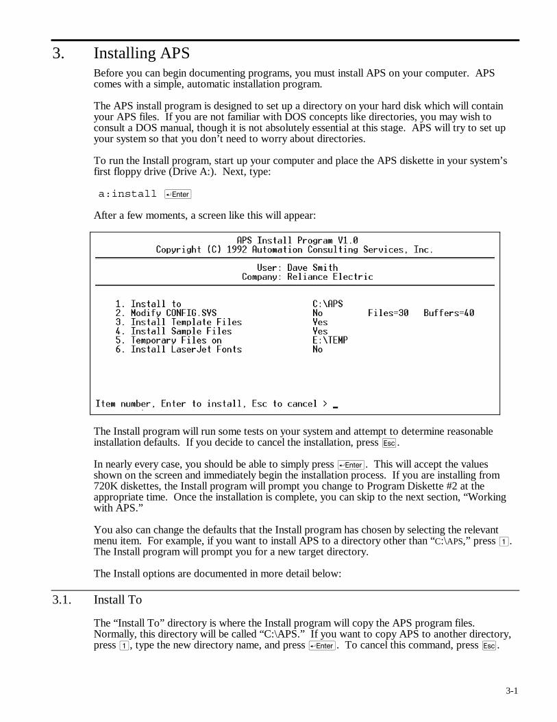
To run the Install program, start up your computer and place the APS diskette in your system’s first floppy drive (Drive A:). Next, type:
a:install r
After a few moments, a screen like this will appear:
The Install program will run some tests on your system and attempt to determine reasonable installation defaults. If you decide to cancel the installation, press q.
In nearly every case, you should be able to simply press r. This will accept the values shown on the screen and immediately begin the installation process. If you are installing from 720K diskettes, the Install program will prompt you change to Program Diskette #2 at the appropriate time. Once the installation is complete, you can skip to the next section, “Working with APS.”
You also can change the defaults that the Install program has chosen by selecting the relevant menu item. For example, if you want to install APS to a directory other than “C:\APS,” press 1. The Install program will prompt you for a new target directory.
The Install options are documented in more detail below:
3.1. Install To
The “Install To” directory is where the Install program will copy the APS program files. Normally, this directory will be called “C:\APS.” If you want to copy APS to another directory, press 1, type the new directory name, and press r. To cancel this command, press q.
3-2
3.2. Modify CONFIG.SYS
IBM Personal Computers and compatibles recognize a special file called “CONFIG.SYS” as long as this file is in the root directory of the disk that the system boots up from. This file contains various startup parameters, read during the startup cycle. These parameters remain in effect until the system is turned off or reset.
In order for APS to operate correctly, this file must contain at least the following lines:
FILES = 20 BUFFERS = 20
Depending on your system, the CONFIG.SYS file may contain only these lines, or there may be many other statements (especially if your computer is connected to a network).
The APS Install program will attempt to locate your system’s CONFIG.SYS file and verify that it contains the necessary lines. If APS finds and verifies the CONFIG.SYS contents, Option 2 will default to “No.” The Install program also will list the number of Files and Buffers found in your configuration.
If APS cannot find a CONFIG.SYS file, or if there are not enough Files or Buffers, the install program will offer to create or update the configuration. The only lines that the install program will change are the Files and Buffers; any other parameters will be left unchanged. The old configuration will also be saved under the name “CONFIG.BAK.”
3.3. Install Template Files
When you begin to document an application program for the first time, APS must create a database to contain your definitions. It can do this in two ways: directly, or from a template.
New databases are opened with default definitions (e.g., system coils). In Direct mode, APS creates these definitions from a list contained in a file called INITDAT. In Template mode, APS makes new databases by “cloning” a set of “template” database files. For example, the template database for AutoMate 40 programs is called “A40.DBT.”
The tradeoff between the two methods is space for speed. In Template mode (the default), APS only needs to perform a “copy” to create a new database. This method is quick, but it requires APS to keep a template database for each processor model. This consumes about 150 kilobytes of disk space.
In Direct mode, each new database must be built and indexed from scratch. This is more time-consuming than the Template procedure, but it requires less disk space.
In practice, you probably will not need to worry about the new database creation method, since both processes provide the same results. Most users create new databases fairly infrequently, so you may wish to save the disk space required by Template mode. To do this, select 3 and answer N to the prompt.
On the other hand, you can modify the Template databases if you are unsatisfied with the standard system definitions. In this case, all new databases would reflect your modified list of system definitions.
You also can delete the template databases later if you wish; APS will automatically return to Direct mode.
3-3
3.4. Install Sample Files
APS is provided with a number of sample documented applications. You may wish to examine and experiment with these sample programs. These files are identified by the word “DEMO” within their filenames.
The Install program will copy the sample files by default. If you wish to disable this function, select 4 at the menu; then type N at the prompt.
3.5. Temporary Files On…
During normal operation, APS will occasionally need to create temporary files. These files exist only while APS is running. When you leave APS, the software will automatically delete them. This command tells APS where to create its temporary files.
If your system has a RAM (virtual) disk with at least 128K of free space, you can speed up APS’s operation somewhat by directing it to create temporary files on the RAM disk. To specify the temporary file drive, type 5, enter the target directory name, and press r.
3.6. Install LaserJet Fonts
If you have a Hewlett-Packard LaserJet™ series printer, you may wish to enable this option, which will install a group of downloadable (soft) fonts. APS will automatically download and use these fonts to produce more attractive printed output.
You should avoid this option if your printer is shared with other users, because these fonts might overwrite other fonts that have already been downloaded. APS uses soft font IDs 1 to 5 and deletes its soft fonts when you exit APS.
You can delete the soft font files if you later decide that you do not want to use them.

4-1
4. Working with APS
DANGER
ONLY QUALIFIED ELECTRICAL PERSONNEL FAMILIAR WITH THE CONSTRUCTION AND OPERATION OF THIS EQUIPMENT AND THE HAZARDS INVOLVED SHOULD INSTALL, ADJUST, OPERATE, AND/OR SERVICE IT. READ AND UNDERSTAND THE APPLICABLE MANUALS IN THEIR ENTIRETY BEFORE PROCEEDING. FAILURE TO OBSERVE THESE PRECAUTIONS COULD RESULT IN SEVERE BODILY INJURY OR LOSS OF LIFE.
APS provides fully documented online and offline programming for the AutoMate series of programmable controllers. It performs all the programming, documenting, configuration, monitoring, and debugging functions that you need to create and maintain AutoMate applications.
APS can be used at all stages of an AutoMate project. During planning, you can use APS to assign I/O addresses and modules. You can use APS’s Name field to link point addresses to wire numbers. As you begin to develop your AutoMate application program, you can use these names instead of point addresses for contact and coil numbers. You can even generate wire tags from the database.
As you work on the application program, the documentation that you have created will appear on the screen. You can refine and improve the documentation as you work. The Macro facility can make generating repetitive groups of sequences less time-consuming. Editing features like cut and paste and search-and-replace contacts make it easy to modify your application. When it comes time to debug your AutoMate application, APS provides complete documented sequence monitoring, powerful register monitoring, and complete I/O point forcing. Use APS’s search commands to locate faulty logic or incorrect contact references.
Once the program is finished, APS’s crossreferenced Documented Listing will provide you with a powerful reference tool for maintaining the program in the future.
The remainder of this section contains an overview of the basic steps required to create and maintain an APS project. The mechanics of each step are described in detail later in this manual.
This introduction refers to A30DEMO, one of the sample programs supplied with APS. This sample program will be installed automatically on your system by APS’s Install utility.
4.1. Starting APS
The APS Install utility will create an APS directory on your system’s hard disk. When you want to run APS, you should change to this directory with the DOS CD command. Your DOS manuals explain changing directories in more detail.
Once you are in the APS directory, type:
APS r
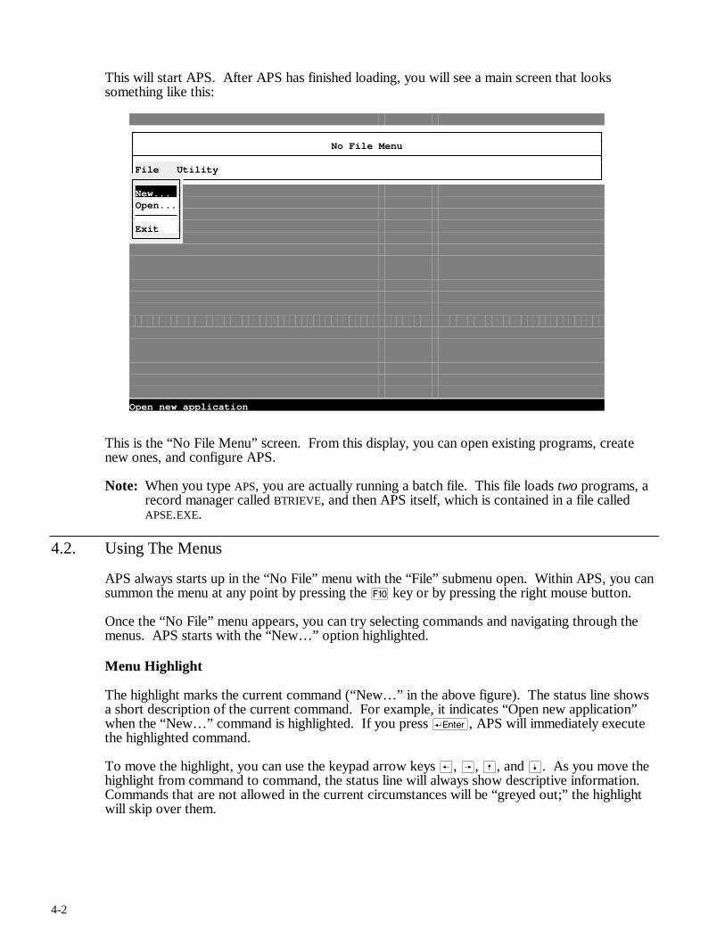
4-2
This will start APS. After APS has finished loading, you will see a main screen that looks something like this:
No File Menu
File Utility
New... Open...
Exit
Open new application
This is the “No File Menu” screen. From this display, you can open existing programs, create new ones, and configure APS.
Note: When you type APS, you are actually running a batch file. This file loads two programs, a record manager called BTRIEVE, and then APS itself, which is contained in a file called APSE.EXE.
4.2. Using The Menus
APS always starts up in the “No File” menu with the “File” submenu open. Within APS, you can summon the menu at any point by pressing the ) key or by pressing the right mouse button.
Once the “No File” menu appears, you can try selecting commands and navigating through the menus. APS starts with the “New…” option highlighted.
Menu Highlight
The highlight marks the current command (“New…” in the above figure). The status line shows a short description of the current command. For example, it indicates “Open new application” when the “New…” command is highlighted. If you press r, APS will immediately execute the highlighted command.
To move the highlight, you can use the keypad arrow keys ®, Â, ß, and Í. As you move the highlight from command to command, the status line will always show descriptive information. Commands that are not allowed in the current circumstances will be “greyed out;” the highlight will skip over them.
4-3
Shortcut Keys
You will notice that each menu item has one letter highlighted. For example, on the “No File” menu, the ‘O’ of “Open…” is highlighted. If you press O, APS will immediately execute the “Open…” command.
Some commands have another key name to the right of the menu text. In the Select menu, for example, “F5” appears to the right of the “Document Pt / Reg” command. This means that you can activate the function in question directly by pressing that key. For example, if you press % in the Sequence Editor, APS will immediately switch to the Point / Register Definition Editor just as if you had called up the menus and picked “Select / Document Pt / Reg.” Many frequently used menu commands have this type of immediate shortcut key.
Immediate shortcut keys use a simple convention. If the key name is preceded by a caret (^), you must press c along with the key name to get the function. For example, the key name “^F6” means “press c + ^.” If the key name is preceded by a lower-case a, you must press a plus the function key. For example, “aF3” means “press a + #.”
Using the Mouse
APS will recognize and use a Microsoft-compatible mouse if your system has one. The right mouse button is used to summon the menu from any point in the program. The left mouse button is used to select menu items. For example, in the “No File” menu, you can click on the “Open…” menu selection to open a file.
Dialog Boxes
When a menu item ends in three periods (…), this means that the item summons a dialog box. Dialog boxes allow you to enter information before activating an APS function. In the “No File” menu, the “New…” and “Open…” selections both lead to dialog boxes.
4.3. The “No File” Menu
There are only a few APS commands available when no project (file) is open. From the “No File” menu, you can create a new project (“File / New…”), open an existing project (“File / Open…”), or configure APS options and preferences. The configuration commands are found on the “Utility” menu.
APS begins with the “File” submenu open. If you press Â, the Utility submenu will open. From the “No File” menu, the following Utility commands are available:
• Printer Cfg
• User Prt Cfg
• Comm. Cfg
• Mono Palette…
• Maintain Backups
• Send ASCII…
• Send Binary…
All of these commands except “Maintain Backups” are documented in the “Utility Menu” section (7.) below.
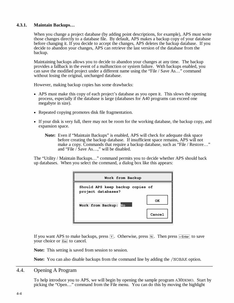
4-4
4.3.1. Maintain Backups…
When you change a project database (by adding point descriptions, for example), APS must write those changes directly to a database file. By default, APS makes a backup copy of your database before changing it. If you decide to accept the changes, APS deletes the backup database. If you decide to abandon your changes, APS can retrieve the last version of the database from the backup.
Maintaining backups allows you to decide to abandon your changes at any time. The backup provides a fallback in the event of a malfunction or system failure. With backups enabled, you can save the modified project under a different name using the “File / Save As…” command without losing the original, unchanged database.
However, making backup copies has some drawbacks:
• APS must make this copy of each project’s database as you open it. This slows the opening process, especially if the database is large (databases for A40 programs can exceed one megabyte in size).
• Repeated copying promotes disk file fragmentation.
• If your disk is very full, there may not be room for the working database, the backup copy, and expansion space.
Note: Even if “Maintain Backups” is enabled, APS will check for adequate disk space before creating the backup database. If insufficient space remains, APS will not make a copy. Commands that require a backup database, such as “File / Restore…” and “File / Save As…,” will be disabled.
The “Utility / Maintain Backups…” command permits you to decide whether APS should back up databases. When you select the command, a dialog box like this appears:
Work from Backup
Should APS keep backup copies of project databases? OK Work from Backup: No Cancel
If you want APS to make backups, press Y. Otherwise, press N. Then press r to save your choice or q to cancel.
Note: This setting is saved from session to session.
Note: You can also disable backups from the command line by adding the /NOBAK option.
4.4. Opening A Program
To help introduce you to APS, we will begin by opening the sample program A30DEMO. Start by picking the “Open…” command from the File menu. You can do this by moving the highlight
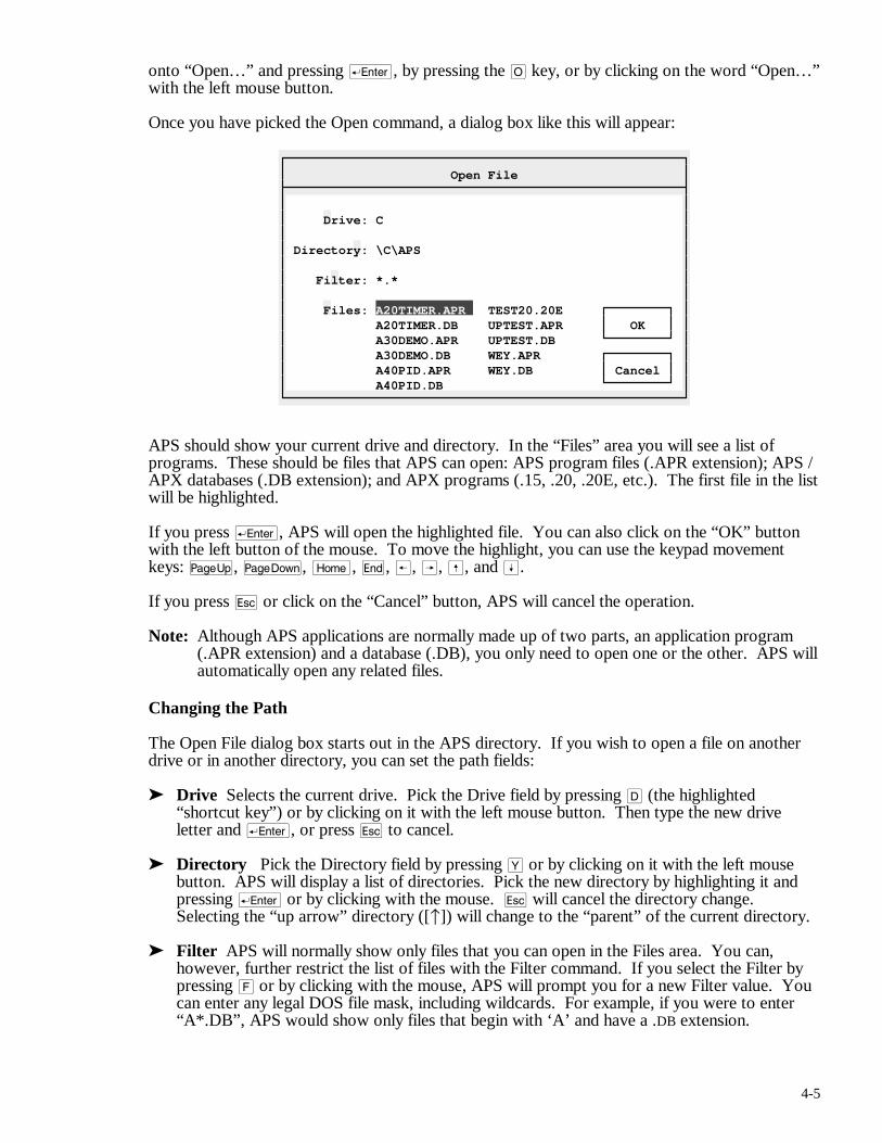
4-5
onto “Open…” and pressing r, by pressing the O key, or by clicking on the word “Open…” with the left mouse button.
Once you have picked the Open command, a dialog box like this will appear:
Open File
Drive: C Directory: \C\APS Filter: *.* Files: A20TIMER.APR TEST20.20E A20TIMER.DB UPTEST.APR OK A30DEMO.APR UPTEST.DB A30DEMO.DB WEY.APR A40PID.APR WEY.DB Cancel A40PID.DB
APS should show your current drive and directory. In the “Files” area you will see a list of programs. These should be files that APS can open: APS program files (.APR extension); APS / APX databases (.DB extension); and APX programs (.15, .20, .20E, etc.). The first file in the list will be highlighted.
If you press r, APS will open the highlighted file. You can also click on the “OK” button with the left button of the mouse. To move the highlight, you can use the keypad movement keys: u, v, m, e, ®, Â, ß, and Í.
If you press q or click on the “Cancel” button, APS will cancel the operation.
Note: Although APS applications are normally made up of two parts, an application program (.APR extension) and a database (.DB), you only need to open one or the other. APS will automatically open any related files.
Changing the Path
The Open File dialog box starts out in the APS directory. If you wish to open a file on another drive or in another directory, you can set the path fields:
➤ Drive Selects the current drive. Pick the Drive field by pressing D (the highlighted “shortcut key”) or by clicking on it with the left mouse button. Then type the new drive letter and r, or press q to cancel.
➤ Directory Pick the Directory field by pressing Y or by clicking on it with the left mouse button. APS will display a list of directories. Pick the new directory by highlighting it and pressing r or by clicking with the mouse. q will cancel the directory change. Selecting the “up arrow” directory ([↑]) will change to the “parent” of the current directory.
➤ Filter APS will normally show only files that you can open in the Files area. You can, however, further restrict the list of files with the Filter command. If you select the Filter by pressing F or by clicking with the mouse, APS will prompt you for a new Filter value. You can enter any legal DOS file mask, including wildcards. For example, if you were to enter “A*.DB”, APS would show only files that begin with ‘A’ and have a .DB extension.
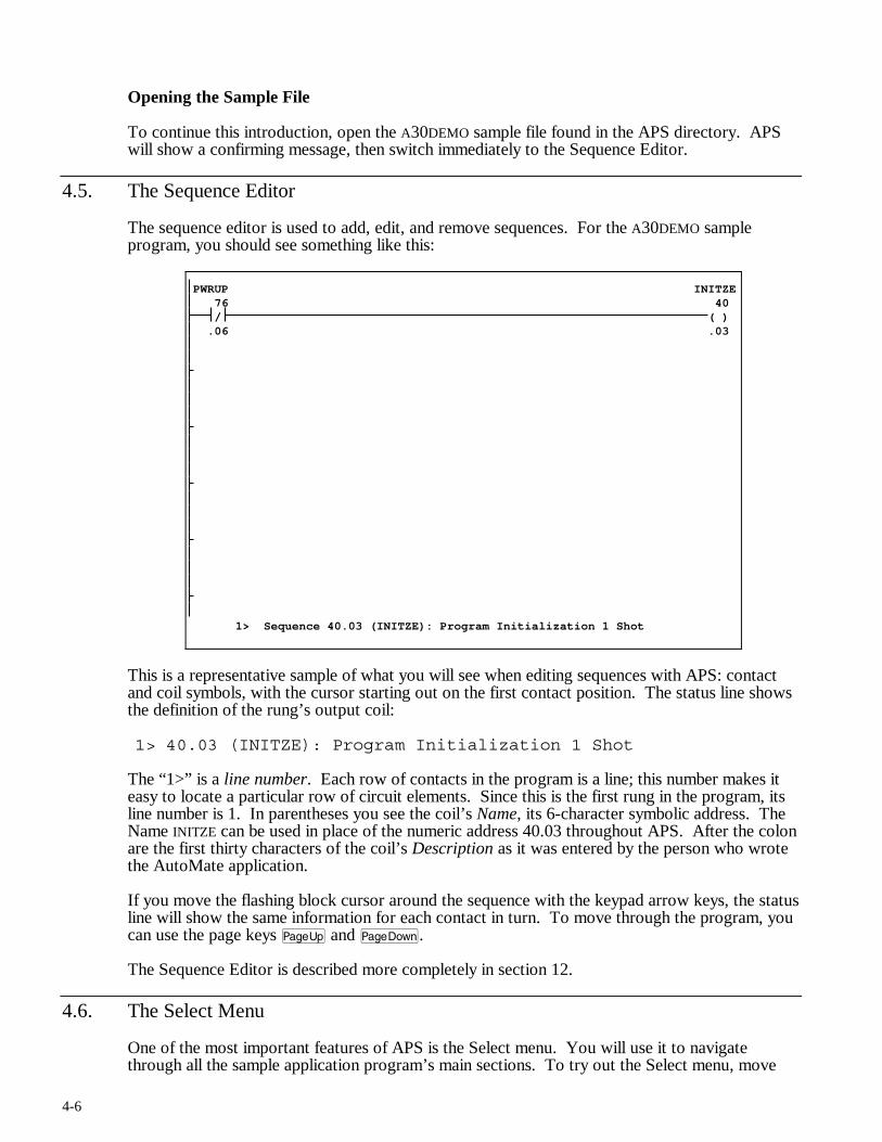
4-6
Opening the Sample File
To continue this introduction, open the A30DEMO sample file found in the APS directory. APS will show a confirming message, then switch immediately to the Sequence Editor.
4.5. The Sequence Editor
The sequence editor is used to add, edit, and remove sequences. For the A30DEMO sample program, you should see something like this:
PWRUP INITZE 76 40
/ ( ) .06 .03
1> Sequence 40.03 (INITZE): Program Initialization 1 Shot
This is a representative sample of what you will see when editing sequences with APS: contact and coil symbols, with the cursor starting out on the first contact position. The status line shows the definition of the rung’s output coil:
1> 40.03 (INITZE): Program Initialization 1 Shot
The “1>” is a line number. Each row of contacts in the program is a line; this number makes it easy to locate a particular row of circuit elements. Since this is the first rung in the program, its line number is 1. In parentheses you see the coil’s Name, its 6-character symbolic address. The Name INITZE can be used in place of the numeric address 40.03 throughout APS. After the colon are the first thirty characters of the coil’s Description as it was entered by the person who wrote the AutoMate application.
If you move the flashing block cursor around the sequence with the keypad arrow keys, the status line will show the same information for each contact in turn. To move through the program, you can use the page keys u and v.
The Sequence Editor is described more completely in section 12.
4.6. The Select Menu
One of the most important features of APS is the Select menu. You will use it to navigate through all the sample application program’s main sections. To try out the Select menu, move
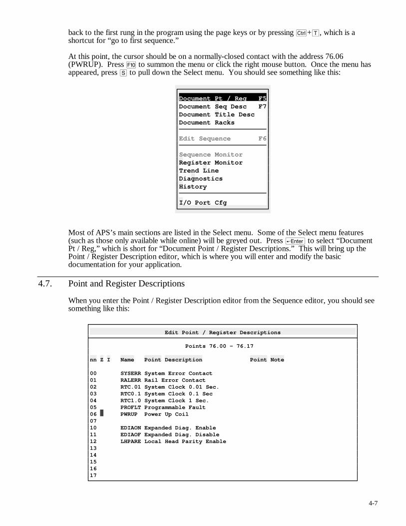
4-7
back to the first rung in the program using the page keys or by pressing c+T, which is a shortcut for “go to first sequence.”
At this point, the cursor should be on a normally-closed contact with the address 76.06 (PWRUP). Press ) to summon the menu or click the right mouse button. Once the menu has appeared, press S to pull down the Select menu. You should see something like this:
Document Pt / Reg F5Document Seq Desc F7Document Title Desc Document Racks
Edit Sequence F6
Sequence Monitor Register Monitor Trend Line Diagnostics History
I/O Port Cfg
Most of APS’s main sections are listed in the Select menu. Some of the Select menu features (such as those only available while online) will be greyed out. Press r to select “Document Pt / Reg,” which is short for “Document Point / Register Descriptions.” This will bring up the Point / Register Description editor, which is where you will enter and modify the basic documentation for your application.
4.7. Point and Register Descriptions
When you enter the Point / Register Description editor from the Sequence editor, you should see something like this:
Edit Point / Register Descriptions
Points 76.00 - 76.17 nn Z I Name Point Description Point Note 00 SYSERR System Error Contact 01 RALERR Rail Error Contact 02 RTC.01 System Clock 0.01 Sec. 03 RTC0.1 System Clock 0.1 Sec 04 RTC1.0 System Clock 1 Sec. 05 PROFLT Programmable Fault 06 PWRUP Power Up Coil 07 10 EDIAON Expanded Diag. Enable 11 EDIAOF Expanded Diag. Disable 12 LHPARE Local Head Parity Enable 13 14 15 16 17
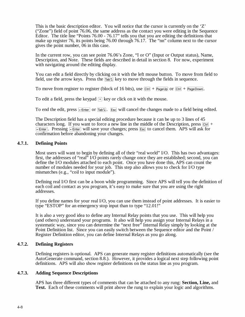
4-8
This is the basic description editor. You will notice that the cursor is currently on the ‘Z’ (“Zone”) field of point 76.06, the same address as the contact you were editing in the Sequence Editor. The title line “Points 76.00 - 76.17” tells you that you are editing the definitions that make up register 76, its points being 76.00 through 76.17. The “nn” column next to the cursor gives the point number, 06 in this case.
In the current row, you can see point 76.06’s Zone, “I or O” (Input or Output status), Name, Description, and Note. These fields are described in detail in section 8. For now, experiment with navigating around the editing display.
You can edit a field directly by clicking on it with the left mouse button. To move from field to field, use the arrow keys. Press the t key to move through the fields in sequence.
To move from register to register (block of 16 bits), use c + u or c + v.
To edit a field, press the keypad > key or click on it with the mouse.
To end the edit, press r or t. q will cancel the changes made to a field being edited.
The Description field has a special editing procedure because it can be up to 3 lines of 45 characters long. If you want to force a new line in the middle of the Description, press c + r. Pressing r will save your changes; press q to cancel them. APS will ask for confirmation before abandoning your changes.
4.7.1. Defining Points
Most users will want to begin by defining all of their “real world” I/O. This has two advantages: first, the addresses of “real” I/O points rarely change once they are established; second, you can define the I/O modules attached to each point. Once you have done this, APS can count the number of modules needed for your job. This step also allows you to check for I/O type mismatches (e.g., “coil to input module”).
Defining real I/O first can be a boon while programming. Since APS will tell you the definition of each coil and contact as you program, it’s easy to make sure that you are using the right addresses.
If you define names for your real I/O, you can use them instead of point addresses. It is easier to type “ESTOP” for an emergency stop input than to type “12.01!”
It is also a very good idea to define any Internal Relay points that you use. This will help you (and others) understand your programs. It also will help you assign your Internal Relays in a systematic way, since you can determine the “next free” Internal Relay simply by looking at the Point Definition list. Since you can easily switch between the Sequence editor and the Point / Register Definition editor, you can define Internal Relays as you go along.
4.7.2. Defining Registers
Defining registers is optional. APS can generate many register definitions automatically (see the AutoGenerate command, section 8.8.). However, it provides a logical next step following point definitions. APS will also show register definitions on the status line as you program.
4.7.3. Adding Sequence Descriptions
APS has three different types of comments that can be attached to any rung: Section, Line, and Text. Each of these comments will print above the rung to explain your logic and algorithms.
4-9
4.7.4. Printing the Documented Ladder Listing
The Documented Ladder Listing is the centerpiece of APS’s many reports. It shows the entire program with an exhaustive set of crossreferences and indexes. Having the Documented Listing at hand can greatly aid in debugging.
4.7.5. Configuring
Before your AutoMate 20, 30, or 40 program can sense or write real world I/O, you must configure the AutoMate’s memory using the “I/O Port Configure” selection. The AutoMate software manual and sections 21. (for the A20) and 20. (for the A30 / A40) of this manual describe this process in more detail.
4.8. Going Online
WARNING
WHEN REPLACING SEQUENCES IN THE ONLINE PROGRAMMING MODE, THERE WILL BE A PERIOD OF TIME WHEN NEITHER THE ORIGINAL SEQUENCE NOR THE NEW SEQUENCE WILL EXECUTE AND UNEXPECTED MACHINE MOVEMENT MAY RESULT. STATION A PERSON IN VIEW OF THE MACHINE AND WITH ACCESS TO AN EMERGENCY STOP SWITCH WHEN UTILIZING THIS MODE. FAILURE TO OBSERVE THESE PRECAUTIONS COULD RESULT IN BODILY INJURY.
The steps described above can be performed either online or offline. To transfer your program to the AutoMate Processor, you will need to go online. You will do this by connecting your computer’s serial port to the Processor’s programming port. Selecting “Go Online” from APS’s File menu (or pressing @) will switch APS into the online mode.
Once you are online, you can transfer your program and configuration to the AutoMate Processor. In online mode, APS’s monitoring, forcing, and debugging features become active.
4.9. Monitoring
Once you have created the program, you will need to debug it. APS has a comprehensive set of monitoring and data logging tools, including a sequence monitor, register monitor, graphical trend-line monitor, and a data logger that can capture data for reports or for “replaying” with the other monitoring tools.
4.10. Other Features
You can use APS to do the following:
• Use the Rack editor to keep track of the cards in your AutoMate racks.
• Copy descriptions, register values, and sequences from other APS applications.
• Use the Macro command to generate repetitive sequences.
• Diagnose AutoMate hardware and configuration problems with APS’s online diagnostics.
• Print wire tags from your point descriptions.
• Use the Drum Table editor to create, edit, and monitor Drum Tables.
• Monitor and tune PID loops with the PID monitor.
4-10
• Use the AutoGen commands to generate register definitions automatically from your application program and point descriptions.
4.11. Compatibility With APX
APS is compatible with Reliance’s other AutoMate programming product, the AutoMate Programming Executive (APX) version 2.5 or later. APS can read and write APX files, but it defaults to working in its native format (.APR extension).
If you are working with both software packages, you must remember to save (or copy) changes to the APX file in the APS directory and load the new APX file into APS, or you must upload the modified program directly from the Processor.
If you don’t remember to save the modified application program files, APS (or APX) may show one program, but the Processor itself may contain something else entirely. The problem can easily snowball if someone tries to debug the program from the Documented Listing.
Once you have an updated APX file, you must load it into APS. This is done with the File menu’s “Load / Save APX” command. The converse is also true; if you make changes with APS and want them to be reflected in APX, you must export the program with the same command.
4.12. Leaving APS
To exit APS and return to DOS, press ) (or click the right mouse button) to bring up the APS menu, then press F (for “File”) and X (for “Exit”). This will return you to DOS after asking you if you want to save any changes that you may have made.
4.13. Starting With an Existing AutoMate Application
4.13.1. Editing a Program Currently Located in an AutoMate Processor
You must always create a project before you can upload an existing application program from an AutoMate Processor. APS needs to have an existing “framework” available before it can accept a program from a Processor. See section 6.1. for more information on creating a new project.
If you want to start editing an existing application program that is currently in an AutoMate Processor, you should create a new project with the proper AutoMate model, then use the “File / Upload (From)” command to retrieve the program.
Please refer to section 12.1.4. for more information on editing an existing application program currently located in an AutoMate Processor.
4.13.2. Editing a Program Created with APX
APS can create a new project directly from your APX-format application program file. Simply use the “File / Open” command to select the desired APX file. APS will automatically determine the correct AutoMate model, create the proper database, and import the APX program for editing.
4.13.3. Editing a Program Created with ACS Products
APS is fully compatible with the Automation Consulting Services, Inc., AutoMate Programmer and AutoMate Documenter versions 2.1 or later. You can freely exchange files between APS and these products.

4-11
4.14. Manual Structure
The rest of this document, after the next section (which describes the APS keyboard) is organized using the same structure as the APS menu system. First come the File and Utility menus, which are the same throughout the program. Next come the APS selections as they are found on the Select menu.

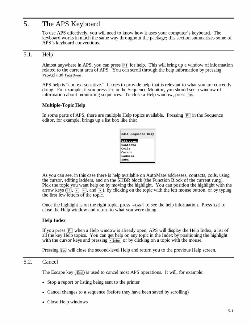
5-1
5. The APS Keyboard To use APS effectively, you will need to know how it uses your computer’s keyboard. The keyboard works in much the same way throughout the package; this section summarizes some of APS’s keyboard conventions.
5.1. Help
Almost anywhere in APS, you can press ! for help. This will bring up a window of information related to the current area of APS. You can scroll through the help information by pressing u and v.
APS help is “context sensitive.” It tries to provide help that is relevant to what you are currently doing. For example, if you press ! in the Sequence Monitor, you should see a window of information about monitoring sequences. To close a Help window, press q.
Multiple-Topic Help
In some parts of APS, there are multiple Help topics available. Pressing ! in the Sequence editor, for example, brings up a list box like this:
Edit Sequence Help
Addresses Contacts Coils Cursor Ladders SHBR
As you can see, in this case there is help available on AutoMate addresses, contacts, coils, using the cursor, editing ladders, and on the SHBR block (the Function Block of the current rung). Pick the topic you want help on by moving the highlight. You can position the highlight with the arrow keys (ß, Í, ®, and Â), by clicking on the topic with the left mouse button, or by typing the first few letters of the topic.
Once the highlight is on the right topic, press r to see the help information. Press q to close the Help window and return to what you were doing.
Help Index
If you press ! when a Help window is already open, APS will display the Help Index, a list of all the key Help topics. You can get help on any topic in the Index by positioning the highlight with the cursor keys and pressing r or by clicking on a topic with the mouse.
Pressing q will close the second-level Help and return you to the previous Help screen.
5.2. Cancel
The Escape key (q) is used to cancel most APS operations. It will, for example:
• Stop a report or listing being sent to the printer
• Cancel changes to a sequence (before they have been saved by scrolling)
• Close Help windows
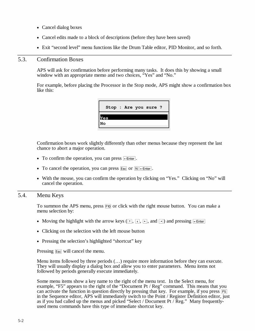
5-2
• Cancel dialog boxes
• Cancel edits made to a block of descriptions (before they have been saved)
• Exit “second level” menu functions like the Drum Table editor, PID Monitor, and so forth.
5.3. Confirmation Boxes
APS will ask for confirmation before performing many tasks. It does this by showing a small window with an appropriate memo and two choices, “Yes” and “No.”
For example, before placing the Processor in the Stop mode, APS might show a confirmation box like this:
Stop : Are you sure ?
Yes No
Confirmation boxes work slightly differently than other menus because they represent the last chance to abort a major operation.
• To confirm the operation, you can press r.
• To cancel the operation, you can press q or Nr.
• With the mouse, you can confirm the operation by clicking on “Yes.” Clicking on “No” will cancel the operation.
5.4. Menu Keys
To summon the APS menu, press ) or click with the right mouse button. You can make a menu selection by:
• Moving the highlight with the arrow keys (ß, Í, ®, and Â) and pressing r
• Clicking on the selection with the left mouse button
• Pressing the selection’s highlighted “shortcut” key
Pressing q will cancel the menu.
Menu items followed by three periods (…) require more information before they can execute. They will usually display a dialog box and allow you to enter parameters. Menu items not followed by periods generally execute immediately.
Some menu items show a key name to the right of the menu text. In the Select menu, for example, “F5” appears to the right of the “Document Pt / Reg” command. This means that you can activate the function in question directly by pressing that key. For example, if you press % in the Sequence editor, APS will immediately switch to the Point / Register Definition editor, just as if you had called up the menus and picked “Select / Document Pt / Reg.” Many frequently-used menu commands have this type of immediate shortcut key.
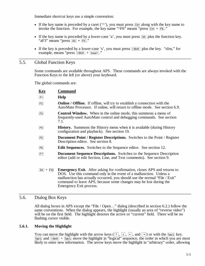
5-3
Immediate shortcut keys use a simple convention:
• If the key name is preceded by a caret (‘^’), you must press c along with the key name to invoke the function. For example, the key name “^F6” means “press c + ^.”
• If the key name is preceded by a lower-case ‘a’, you must press a plus the function key. “aF3” means “press a + #.”
• If the key is preceded by a lower-case ‘s’, you must press f plus the key. “sIns,” for example, means “press f + i.”
5.5. Global Function Keys
Some commands are available throughout APS. These commands are always invoked with the Function Keys to the left (or above) your keyboard.
The global commands are:
Key Command
! Help
@ Online / Offline. If offline, will try to establish a connection with the AutoMate Processor. If online, will return to offline mode. See section 6.9.
# Control Window. When in the online mode, this summons a menu of frequently-used AutoMate control and debugging commands. See section 7.1.
$ History. Summons the History menu when it is available (during History configuration and playback). See section 19.
% Document Point / Register Descriptions. Switches to the Point / Register Description editor. See section 8.
^ Edit Sequences. Switches to the Sequence editor. See section 12.
& Document Sequence Descriptions. Switches to the Sequence Description editor (add or edit Section, Line, and Text comments). See section 9.
a + ) Emergency Exit. After asking for confirmation, closes APS and returns to DOS. Use this command only in the event of a malfunction. Unless a malfunction has actually occurred, you should use the normal “File / Exit” command to leave APS, because some changes may be lost during the Emergency Exit process.
5.6. Dialog Box Keys
All dialog boxes in APS except the “File / Open…” dialog (described in section 6.2.) follow the same conventions. When the dialog appears, the highlight (usually an area of “reverse video”) will be on the first field. The highlight denotes the active or “current” field. There will be no flashing cursor visible.
5.6.1. Moving the Highlight
You can move the highlight with the arrow keys (ß, Í, ®, and Â) or with the t key. t and f + t move the highlight in “logical” sequence, the order in which you are most likely to enter new information. The arrow keys move the highlight in “arbitrary” order, allowing
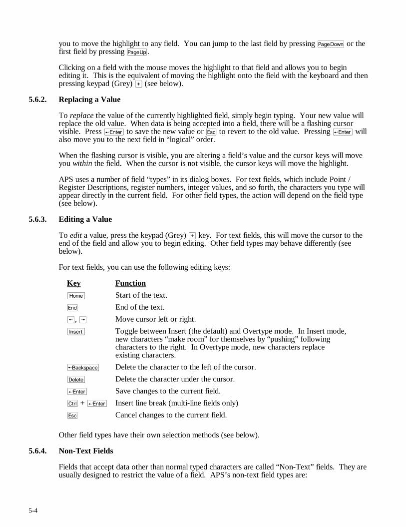
5-4
you to move the highlight to any field. You can jump to the last field by pressing v or the first field by pressing u.
Clicking on a field with the mouse moves the highlight to that field and allows you to begin editing it. This is the equivalent of moving the highlight onto the field with the keyboard and then pressing keypad (Grey) > (see below).
5.6.2. Replacing a Value
To replace the value of the currently highlighted field, simply begin typing. Your new value will replace the old value. When data is being accepted into a field, there will be a flashing cursor visible. Press r to save the new value or q to revert to the old value. Pressing r will also move you to the next field in “logical” order.
When the flashing cursor is visible, you are altering a field’s value and the cursor keys will move you within the field. When the cursor is not visible, the cursor keys will move the highlight.
APS uses a number of field “types” in its dialog boxes. For text fields, which include Point / Register Descriptions, register numbers, integer values, and so forth, the characters you type will appear directly in the current field. For other field types, the action will depend on the field type (see below).
5.6.3. Editing a Value
To edit a value, press the keypad (Grey) > key. For text fields, this will move the cursor to the end of the field and allow you to begin editing. Other field types may behave differently (see below).
For text fields, you can use the following editing keys:
Key Function
m Start of the text.
e End of the text.
®, Â Move cursor left or right.
i Toggle between Insert (the default) and Overtype mode. In Insert mode, new characters “make room” for themselves by “pushing” following characters to the right. In Overtype mode, new characters replace existing characters.
b Delete the character to the left of the cursor.
d Delete the character under the cursor.
r Save changes to the current field.
c + r Insert line break (multi-line fields only)
q Cancel changes to the current field.
Other field types have their own selection methods (see below).
5.6.4. Non-Text Fields
Fields that accept data other than normal typed characters are called “Non-Text” fields. They are usually designed to restrict the value of a field. APS’s non-text field types are:
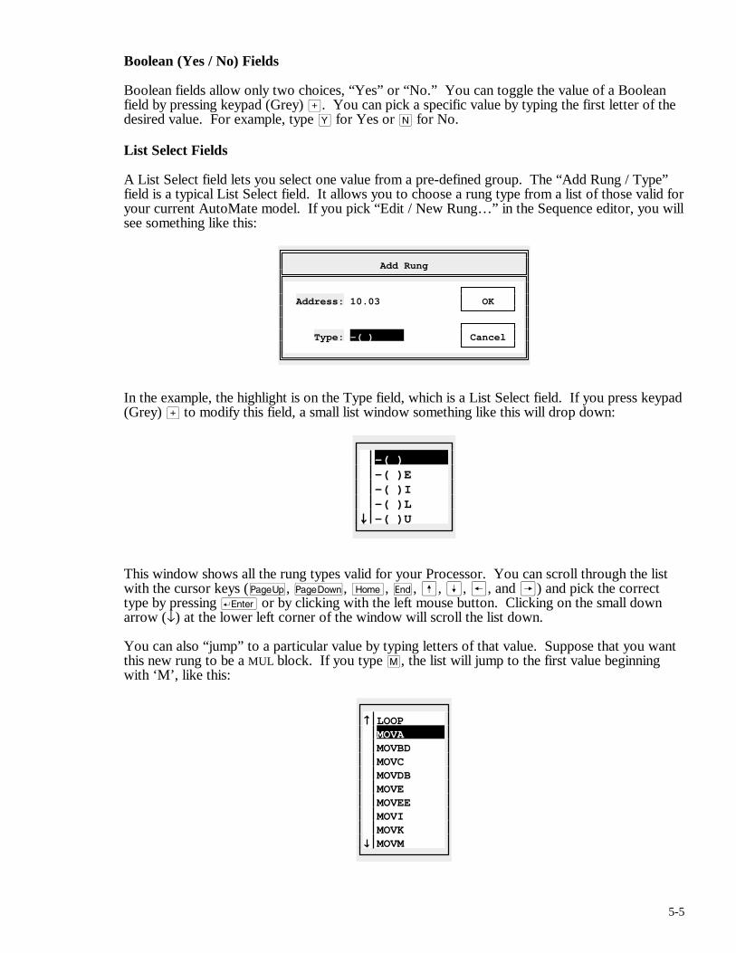
5-5
Boolean (Yes / No) Fields
Boolean fields allow only two choices, “Yes” or “No.” You can toggle the value of a Boolean field by pressing keypad (Grey) >. You can pick a specific value by typing the first letter of the desired value. For example, type Y for Yes or N for No.
List Select Fields
A List Select field lets you select one value from a pre-defined group. The “Add Rung / Type” field is a typical List Select field. It allows you to choose a rung type from a list of those valid for your current AutoMate model. If you pick “Edit / New Rung…” in the Sequence editor, you will see something like this:
Add Rung
Address: 10.03 OK Type: -( ) Cancel
In the example, the highlight is on the Type field, which is a List Select field. If you press keypad (Grey) > to modify this field, a small list window something like this will drop down:
-( ) -( )E -( )I -( )L -( )U
This window shows all the rung types valid for your Processor. You can scroll through the list with the cursor keys (u, v, m, e, ß, Í, ®, and Â) and pick the correct type by pressing r or by clicking with the left mouse button. Clicking on the small down arrow (↓) at the lower left corner of the window will scroll the list down.
You can also “jump” to a particular value by typing letters of that value. Suppose that you want this new rung to be a MUL block. If you type M, the list will jump to the first value beginning with ‘M’, like this:
LOOP MOVA MOVBD MOVC MOVDB MOVE MOVEE MOVI MOVK MOVM
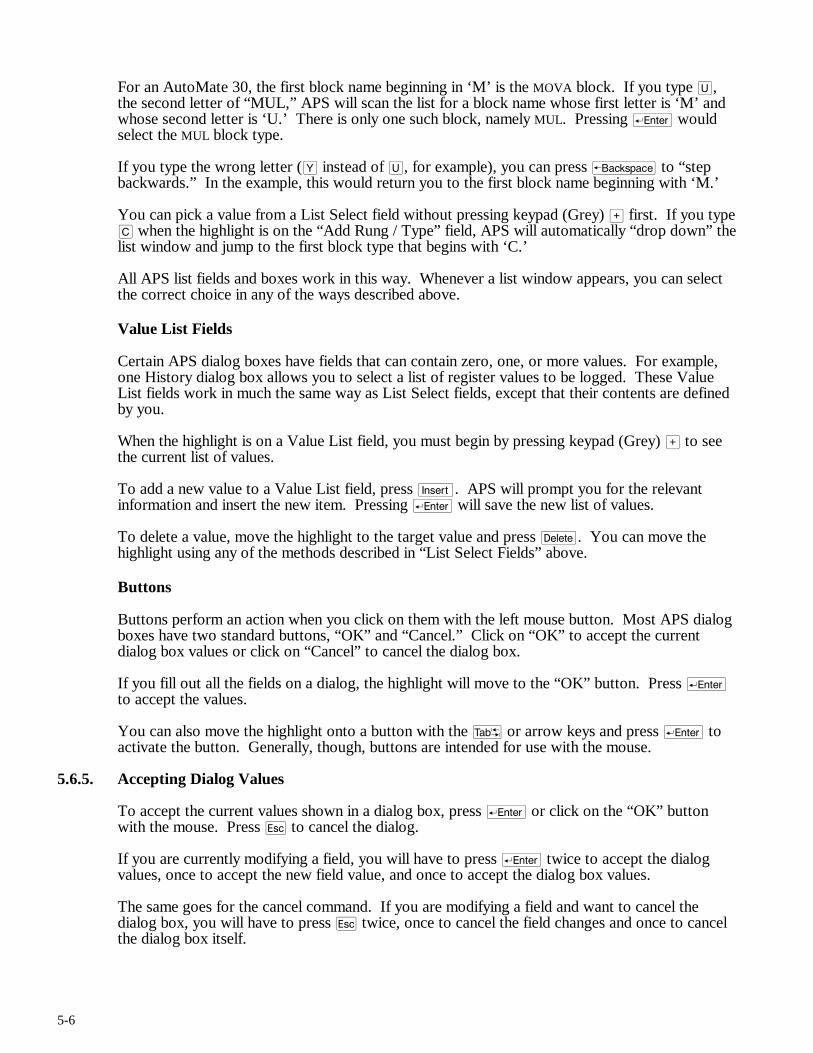
5-6
For an AutoMate 30, the first block name beginning in ‘M’ is the MOVA block. If you type U, the second letter of “MUL,” APS will scan the list for a block name whose first letter is ‘M’ and whose second letter is ‘U.’ There is only one such block, namely MUL. Pressing r would select the MUL block type.
If you type the wrong letter (Y instead of U, for example), you can press b to “step backwards.” In the example, this would return you to the first block name beginning with ‘M.’
You can pick a value from a List Select field without pressing keypad (Grey) > first. If you type C when the highlight is on the “Add Rung / Type” field, APS will automatically “drop down” the list window and jump to the first block type that begins with ‘C.’
All APS list fields and boxes work in this way. Whenever a list window appears, you can select the correct choice in any of the ways described above.
Value List Fields
Certain APS dialog boxes have fields that can contain zero, one, or more values. For example, one History dialog box allows you to select a list of register values to be logged. These Value List fields work in much the same way as List Select fields, except that their contents are defined by you.
When the highlight is on a Value List field, you must begin by pressing keypad (Grey) > to see the current list of values.
To add a new value to a Value List field, press i. APS will prompt you for the relevant information and insert the new item. Pressing r will save the new list of values.
To delete a value, move the highlight to the target value and press d. You can move the highlight using any of the methods described in “List Select Fields” above.
Buttons
Buttons perform an action when you click on them with the left mouse button. Most APS dialog boxes have two standard buttons, “OK” and “Cancel.” Click on “OK” to accept the current dialog box values or click on “Cancel” to cancel the dialog box.
If you fill out all the fields on a dialog, the highlight will move to the “OK” button. Press r to accept the values.
You can also move the highlight onto a button with the t or arrow keys and press r to activate the button. Generally, though, buttons are intended for use with the mouse.
5.6.5. Accepting Dialog Values
To accept the current values shown in a dialog box, press r or click on the “OK” button with the mouse. Press q to cancel the dialog.
If you are currently modifying a field, you will have to press r twice to accept the dialog values, once to accept the new field value, and once to accept the dialog box values.
The same goes for the cancel command. If you are modifying a field and want to cancel the dialog box, you will have to press q twice, once to cancel the field changes and once to cancel the dialog box itself.
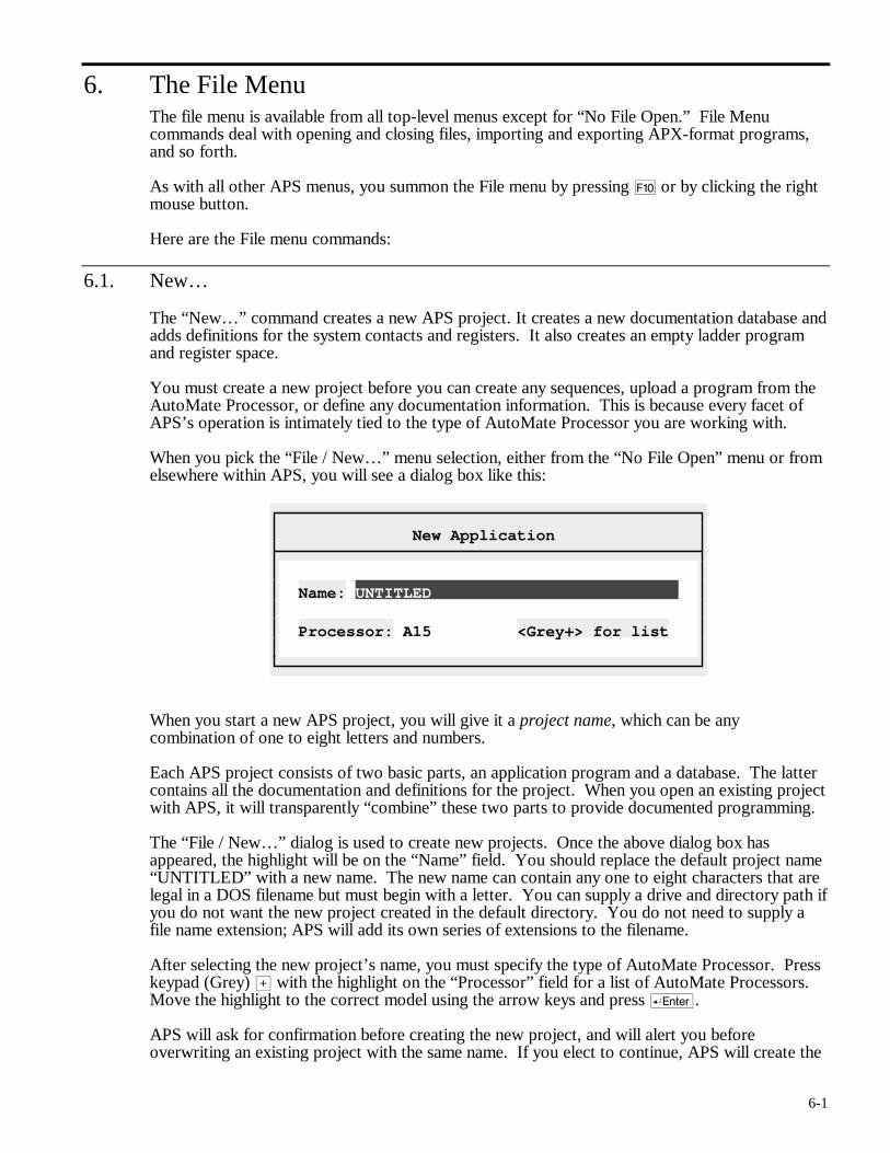
6-1
6. The File Menu The file menu is available from all top-level menus except for “No File Open.” File Menu commands deal with opening and closing files, importing and exporting APX-format programs, and so forth.
As with all other APS menus, you summon the File menu by pressing ) or by clicking the right mouse button.
Here are the File menu commands:
6.1. New…
The “New…” command creates a new APS project. It creates a new documentation database and adds definitions for the system contacts and registers. It also creates an empty ladder program and register space.
You must create a new project before you can create any sequences, upload a program from the AutoMate Processor, or define any documentation information. This is because every facet of APS’s operation is intimately tied to the type of AutoMate Processor you are working with.
When you pick the “File / New…” menu selection, either from the “No File Open” menu or from elsewhere within APS, you will see a dialog box like this:
New Application
Name: UNTITLED Processor: A15 <Grey+> for list
When you start a new APS project, you will give it a project name, which can be any combination of one to eight letters and numbers.
Each APS project consists of two basic parts, an application program and a database. The latter contains all the documentation and definitions for the project. When you open an existing project with APS, it will transparently “combine” these two parts to provide documented programming.
The “File / New…” dialog is used to create new projects. Once the above dialog box has appeared, the highlight will be on the “Name” field. You should replace the default project name “UNTITLED” with a new name. The new name can contain any one to eight characters that are legal in a DOS filename but must begin with a letter. You can supply a drive and directory path if you do not want the new project created in the default directory. You do not need to supply a file name extension; APS will add its own series of extensions to the filename.
After selecting the new project’s name, you must specify the type of AutoMate Processor. Press keypad (Grey) > with the highlight on the “Processor” field for a list of AutoMate Processors. Move the highlight to the correct model using the arrow keys and press r.
APS will ask for confirmation before creating the new project, and will alert you before overwriting an existing project with the same name. If you elect to continue, APS will create the
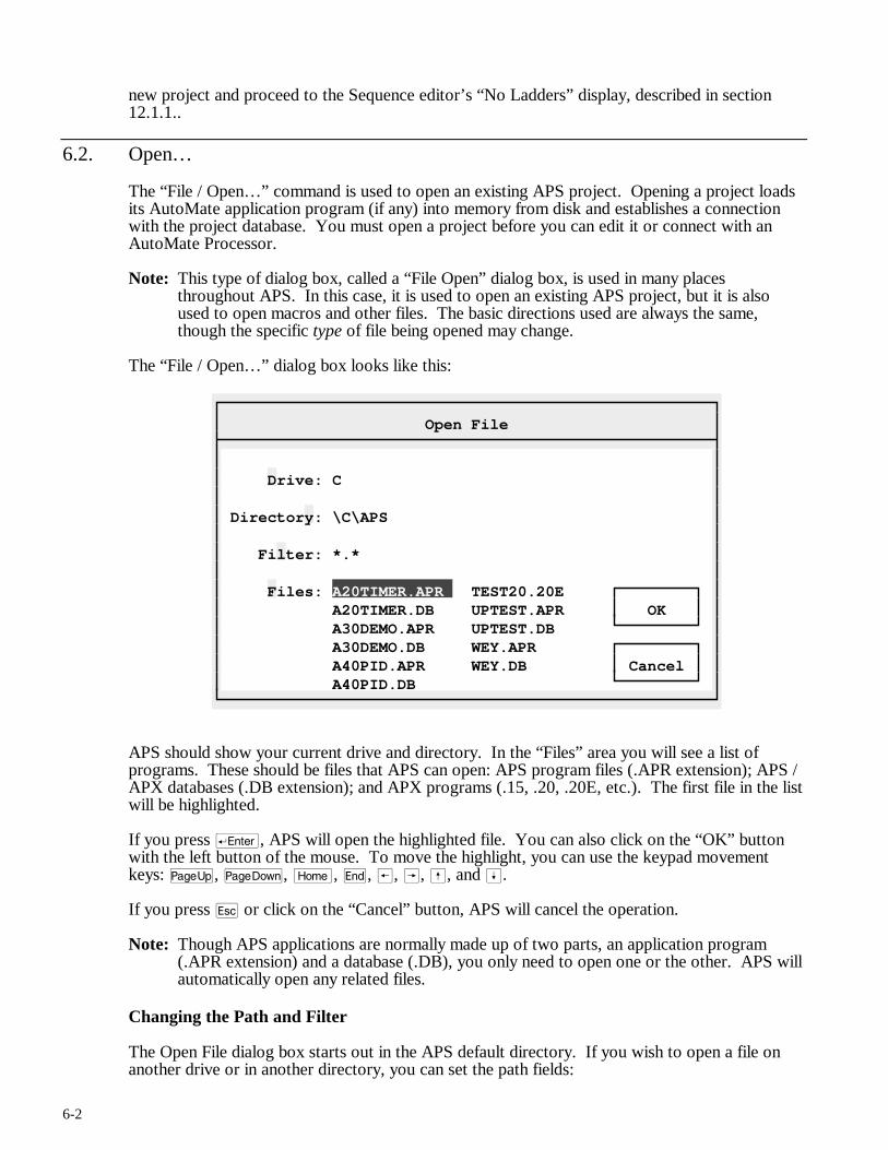
6-2
new project and proceed to the Sequence editor’s “No Ladders” display, described in section 12.1.1..
6.2. Open…
The “File / Open…” command is used to open an existing APS project. Opening a project loads its AutoMate application program (if any) into memory from disk and establishes a connection with the project database. You must open a project before you can edit it or connect with an AutoMate Processor.
Note: This type of dialog box, called a “File Open” dialog box, is used in many places throughout APS. In this case, it is used to open an existing APS project, but it is also used to open macros and other files. The basic directions used are always the same, though the specific type of file being opened may change.
The “File / Open…” dialog box looks like this:
Open File
Drive: C Directory: \C\APS Filter: *.* Files: A20TIMER.APR TEST20.20E A20TIMER.DB UPTEST.APR OK A30DEMO.APR UPTEST.DB A30DEMO.DB WEY.APR A40PID.APR WEY.DB Cancel A40PID.DB
APS should show your current drive and directory. In the “Files” area you will see a list of programs. These should be files that APS can open: APS program files (.APR extension); APS / APX databases (.DB extension); and APX programs (.15, .20, .20E, etc.). The first file in the list will be highlighted.
If you press r, APS will open the highlighted file. You can also click on the “OK” button with the left button of the mouse. To move the highlight, you can use the keypad movement keys: u, v, m, e, ®, Â, ß, and Í.
If you press q or click on the “Cancel” button, APS will cancel the operation.
Note: Though APS applications are normally made up of two parts, an application program (.APR extension) and a database (.DB), you only need to open one or the other. APS will automatically open any related files.
Changing the Path and Filter
The Open File dialog box starts out in the APS default directory. If you wish to open a file on another drive or in another directory, you can set the path fields:
6-3
➤ Drive Selects the current drive. Pick the Drive field by pressing D (the highlighted “shortcut key”) or by clicking on it with the left mouse button. Then type the new drive letter and r or press q to cancel.
➤ Directory Pick the Directory field by pressing Y or by clicking on it with the left mouse button. APS will display a list of directories. Pick the new directory by highlighting it and pressing r or by clicking with the mouse. q will cancel the directory change. Selecting the “up arrow” directory ([↑]) will change to the “parent” of the current directory.
➤ Filter APS will normally show only files that you can open in the Files area. You can, however, further restrict the list of files with the Filter command. If you select the Filter by pressing F or by clicking with the mouse, APS will prompt you for a new Filter value. You can enter any legal DOS file mask, including wildcards. For example, if you were to enter “A*.DB”, APS would show only files that begin with ‘A’ and have a .DB extension.
Note: You can start APS with a project open by typing (from DOS):
APS projectname r
6.3. Save
The “File / Save” command immediately saves the current AutoMate application program and database to disk. You may want use this command periodically if you are entering a large number of new sequences or making many database changes. Saving in this way will protect you if there is a system failure or power outage (for example).
APS will always give you an opportunity to save changes made to the current project before exiting to DOS or opening a new project.
Note: If “Maintain Backups” mode (see section 4.3.1.) is enabled, the Save command saves changes to both the application program and the project database.
If “Maintain Backups” is disabled, or if there was insufficient disk space available for APS to create a backup copy, this command does not save the project database. Under these circumstances, there is no need to save the database explicitly; changes are recorded to the database as they are made.
Backup Version
When you save your AutoMate application program, either using the “File / Save” command or by leaving the project, APS keeps a backup copy. This backup is called the “.OPR” file. When you save a new version of your program to disk, the previous application program (“.APR”) file is renamed to “.OPR”.
If your APS project were called “WINDER”, after a save operation, you will have files called WINDER.APR and WINDER.OPR. WINDER.APR would be the current AutoMate program. WINDER.OPR would be the last saved program.
With this system, you always have a backup file in case you make changes that you want to undo. To replace the current version with the backup, simply copy the “.OPR” file over the “.APR” file. For example, type:
COPY WINDER.OPR WINDER.APR r
at the DOS prompt.
6-4
6.4. Save As…
The “File / Save As…” command allows you to save the current project under a different name. The Save As command will create a new project database and application program file.
Selecting the command will display a dialog box that asks for the new project name. Enter a valid name (with drive and path, if needed) and press r to create the new project. If a project with the name you select already exists, APS will ask for confirmation before overwriting it. Press q to cancel the “Save As” operation.
Note: The “File / Save As…” command is only available if “Maintain Backups” mode (see section 4.3.1.) is enabled. If “Maintain Backups” is disabled, or if there was insufficient disk space available for APS to make a backup, the “Save As…” command will be greyed out.
6.5. Restore
The “File / Restore” command allows you to cancel any changes you have made to your APS project during the current session (or since the last “File / Save” operation). If you select “File / Restore,” APS will ask for confirmation, then return to the last saved version of the current project.
Note: The “File / Restore” command is only available if “Maintain Backups” mode (see section 4.3.1.) is enabled. If “Maintain Backups” is disabled, or if there was insufficient disk space available for APS to make a backup, the “Restore” command will be greyed out.
6.6. Save / Load APX…
To provide compatibility with the AutoMate Programming Executive (APX), APS can read and write files in APX’s native format. Picking “File / Save / Load APX…” will produce a “Load or Save” submenu. Choose “Save” to write the current application program as an APX file. Choose “Load” to read an APX file into memory over the current application program.
There is no need to supply a filename to either the Load APX or the Save APX commands. The correct filename will be computed automatically by APS from the project’s name and AutoMate model. For example, an A30E project called “WINDER” would read or write to the file WINDER.30E.
6.7. Download (To)…
This command, available only while APS is online, transfers the program from the personal computer’s memory to the AutoMate Processor’s memory. The Download command will write the I/O Port Configuration, data register values, and application program into the Processor’s memory.
APS will always request confirmation before downloading the program. If you are working with an A15 or A20 Processor, the download will begin immediately after confirmation.
For A30 and A40 series Processors, there are two types of downloads available, “Rapid” and “Normal.” APS will ask you to specify the type of download before starting.
When connected to the AutoMate Processor’s Programming port, you should generally use the Rapid mode as it is far faster than the Normal mode. If APS reports errors during the transfer, try the Normal mode.
6-5
GOTO Checks
Before downloading a program to the Processor, APS will automatically check to see that all GOTO and GOSUB blocks refer to valid coil numbers.
If your program contains GOTO or GOSUB blocks that refer to nonexistent coils, APS will display a message and cancel the download.
20000 Register Checks
On Processors that support registers in the 20000 range, APS also checks to see that you have not referred to illegal registers. In other words, the software checks all function blocks to ensure none of them refer to register addresses above the current Register Limit. APS will also detect register Tables that exceed the Register Limit.
If your application program contains register addresses above the Register Limit, APS will display an error message and cancel the download.
Note: The Processor must be in the Stop mode before you can use the Download command.
Note: APS will cancel the Download if the application program fails the GOTO or 20000 register checks.
Note: The Rapid Download command is not available when you are communicating via an R-Net PC Link card or via a Gateway.
6.8. Upload (From)
Available while online, the Upload (From) command retrieves the current AutoMate program and stores it in the personal computer’s memory. It transfers the I/O Port configuration, the data register values, and the application program. Any program currently in the computer’s memory will be lost.
APS will ask for confirmation before beginning an Upload.
6.9. Go Online…
Shortcut key: @
The “Go Online…” command establishes a connection between the AutoMate and APS. You must go online whenever you wish to directly manipulate the AutoMate Processor. You must be online to transfer programs, read or modify register values, monitor sequences, and so forth. You may select the “File / Go Online” command either from the File menu or by pressing @.
WARNING
WHEN REPLACING SEQUENCES IN THE ONLINE PROGRAMMING MODE, THERE WILL BE A PERIOD OF TIME WHEN NEITHER THE ORIGINAL SEQUENCE NOR THE NEW SEQUENCE WILL EXECUTE AND UNEXPECTED MACHINE MOVEMENT MAY RESULT. STATION A PERSON IN VIEW OF THE MACHINE AND WITH ACCESS TO AN EMERGENCY STOP SWITCH WHEN UTILIZING THIS MODE. FAILURE TO OBSERVE THESE PRECAUTIONS COULD RESULT IN BODILY INJURY.
Direct Connection
If you are plugged directly into the AutoMate Processor’s Programming Port, or into a Serial Communications Card, APS should connect automatically and display an information box about
6-6
the Processor’s status. There may be a brief pause before a connection is established via a Serial Communications Card; APS must “hunt” for the Serial Comm. Card’s address before going online.
Gateway Communications
If you are connected to a 45C27 AutoMate Gateway, APS may need some information before it can communicate. If the Gateway has not been set up, APS will display a Gateway Setup dialog and ask you for the Gateway’s node number, the maximum number of nodes, and the Gateway Configuration byte. Please consult your Gateway manual (J-3028) if you need more information on these parameters.
Once the Gateway is set up, you must specify the address of the AutoMate Processor. This address consists of the node number of the R-Net Processor in the target rack and the slot number of the AutoMate Processor. APS “remembers” this address from session to session; once you have established the right address, you should be able to simply press r when APS shows the “R-Net Destination” dialog.
When APS is online, the word “Online” will appear in the Sequence editor’s status line.
Note: When first installed, APS assumes that you will be communicating via your computer’s COM1 serial port at 9600 baud, 8 data bits, no parity, and 1 stop bit. If these assumptions are not correct, you should use the Utility menu’s “Communications Configuration” command to set the correct serial port parameters. Refer to section 7.5. for more information.
The R-Net PC Link
If you are communcating over R-Net using the R-Net PC adaptor card, APS will ask for a destination node and slot just as if you were connected to a Gateway. Before the R-Net PC can communicate over the R-Net network, it must be initialized, a process that may include loading the R-Net PC Executive onto the board. Section 7.5.2. describes R-Net PC Link operation in more detail.
Force Online
Under certain circumstances, you may not be able to get online using the normal “File / Go Online…” command. If your AutoMate Processor has malfunctioned, or if you are otherwise unable to get online using this command, you may need to set up communications manually. You can do this using the “Utility / Communications Addresses…” command described in section 7.9.
Going online in this way is called “Forcing Online” since you are connecting to the AutoMate Processor without the usual tests performed by the “File / Go Online…” command.
Note that Forcing Online will only work if the connection to the Processor is basically sound. In other words, use Force Online if the “File / Go Online…” gives a processor error, especially “Error 61.” Communications errors like “Timeout” and “Communications Checksum Error” will not be prevented by the Force Online command; these are symptoms of a fault in the connection between your computer and the AutoMate processor.
6.10. Go Offline
Shortcut key: @
When online, the “Go Offline” command will terminate the connection to the AutoMate Processor and return to offline mode.

6-7
6.11. Exit
Use the “File / Exit” command to leave APS and return to DOS. If you have made any changes that have not been saved, APS will give you a chance to save them before returning to DOS.
6.12. About…
The “File / About” command displays some useful information about the current APS project, including your APS version number, the size of the program, the number of items in the database, and so forth. In the upper right corner of the box, you will see the words “EMS 4.0” if APS is using Expanded Memory or “Disk” if it is using a disk-based temporary file.

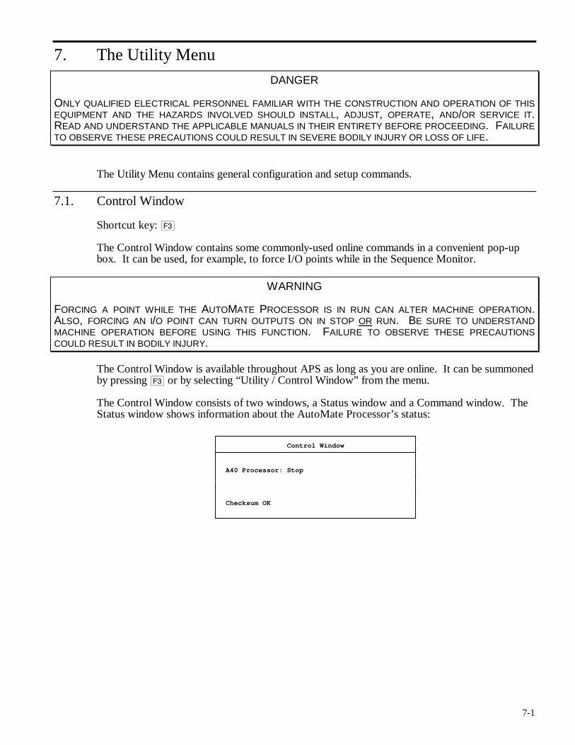
7-1
7. The Utility Menu
DANGER
ONLY QUALIFIED ELECTRICAL PERSONNEL FAMILIAR WITH THE CONSTRUCTION AND OPERATION OF THIS EQUIPMENT AND THE HAZARDS INVOLVED SHOULD INSTALL, ADJUST, OPERATE, AND/OR SERVICE IT. READ AND UNDERSTAND THE APPLICABLE MANUALS IN THEIR ENTIRETY BEFORE PROCEEDING. FAILURE TO OBSERVE THESE PRECAUTIONS COULD RESULT IN SEVERE BODILY INJURY OR LOSS OF LIFE.
The Utility Menu contains general configuration and setup commands.
7.1. Control Window
Shortcut key: #
The Control Window contains some commonly-used online commands in a convenient pop-up box. It can be used, for example, to force I/O points while in the Sequence Monitor.
WARNING
FORCING A POINT WHILE THE AUTOMATE PROCESSOR IS IN RUN CAN ALTER MACHINE OPERATION. ALSO, FORCING AN I/O POINT CAN TURN OUTPUTS ON IN STOP OR RUN. BE SURE TO UNDERSTAND MACHINE OPERATION BEFORE USING THIS FUNCTION. FAILURE TO OBSERVE THESE PRECAUTIONS COULD RESULT IN BODILY INJURY.
The Control Window is available throughout APS as long as you are online. It can be summoned by pressing # or by selecting “Utility / Control Window” from the menu.
The Control Window consists of two windows, a Status window and a Command window. The Status window shows information about the AutoMate Processor’s status:
Control Window
A40 Processor: Stop Checksum OK
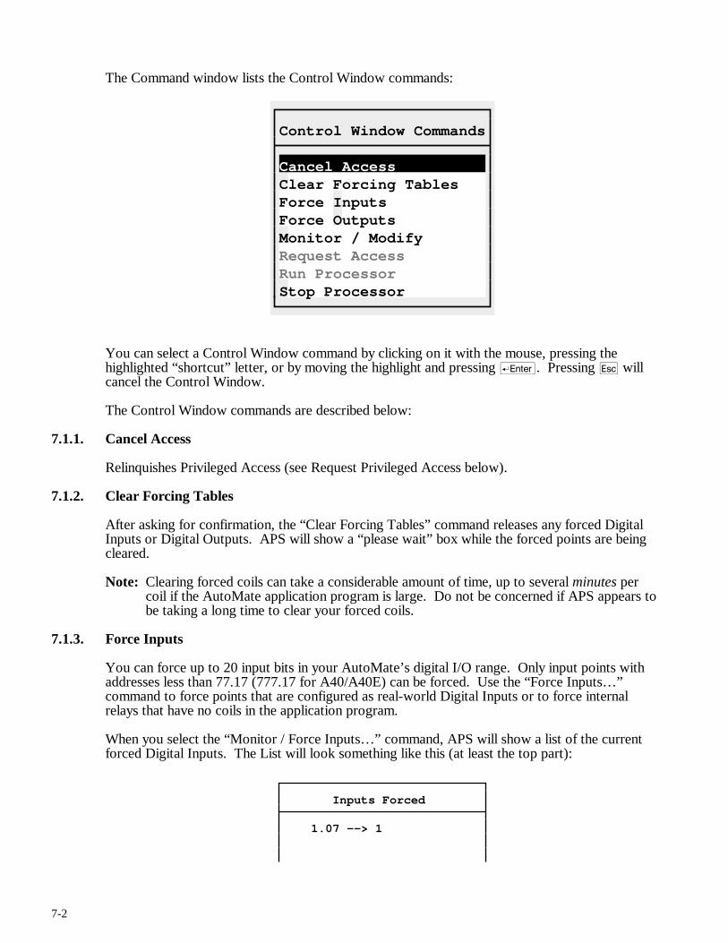
7-2
The Command window lists the Control Window commands:
Control Window Commands
Cancel Access Clear Forcing Tables Force Inputs Force Outputs Monitor / Modify Request Access Run Processor Stop Processor
You can select a Control Window command by clicking on it with the mouse, pressing the highlighted “shortcut” letter, or by moving the highlight and pressing r. Pressing q will cancel the Control Window.
The Control Window commands are described below:
7.1.1. Cancel Access
Relinquishes Privileged Access (see Request Privileged Access below).
7.1.2. Clear Forcing Tables
After asking for confirmation, the “Clear Forcing Tables” command releases any forced Digital Inputs or Digital Outputs. APS will show a “please wait” box while the forced points are being cleared.
Note: Clearing forced coils can take a considerable amount of time, up to several minutes per coil if the AutoMate application program is large. Do not be concerned if APS appears to be taking a long time to clear your forced coils.
7.1.3. Force Inputs
You can force up to 20 input bits in your AutoMate’s digital I/O range. Only input points with addresses less than 77.17 (777.17 for A40/A40E) can be forced. Use the “Force Inputs…” command to force points that are configured as real-world Digital Inputs or to force internal relays that have no coils in the application program.
When you select the “Monitor / Force Inputs…” command, APS will show a list of the current forced Digital Inputs. The List will look something like this (at least the top part):
Inputs Forced
1.07 --> 1
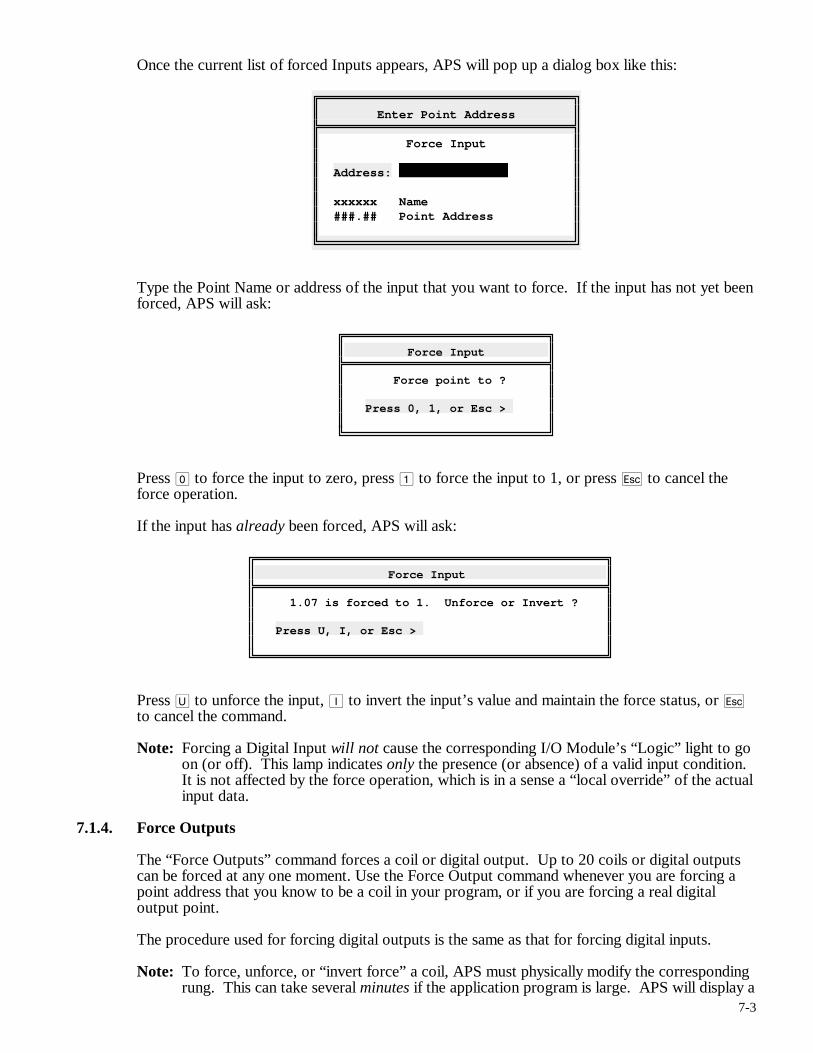
7-3
Once the current list of forced Inputs appears, APS will pop up a dialog box like this:
Enter Point Address
Force Input Address: xxxxxx Name ###.## Point Address
Type the Point Name or address of the input that you want to force. If the input has not yet been forced, APS will ask:
Force Input
Force point to ? Press 0, 1, or Esc >
Press 0 to force the input to zero, press 1 to force the input to 1, or press q to cancel the force operation.
If the input has already been forced, APS will ask:
Force Input
1.07 is forced to 1. Unforce or Invert ? Press U, I, or Esc >
Press U to unforce the input, I to invert the input’s value and maintain the force status, or q to cancel the command.
Note: Forcing a Digital Input will not cause the corresponding I/O Module’s “Logic” light to go on (or off). This lamp indicates only the presence (or absence) of a valid input condition. It is not affected by the force operation, which is in a sense a “local override” of the actual input data.
7.1.4. Force Outputs
The “Force Outputs” command forces a coil or digital output. Up to 20 coils or digital outputs can be forced at any one moment. Use the Force Output command whenever you are forcing a point address that you know to be a coil in your program, or if you are forcing a real digital output point.
The procedure used for forcing digital outputs is the same as that for forcing digital inputs.
Note: To force, unforce, or “invert force” a coil, APS must physically modify the corresponding rung. This can take several minutes if the application program is large. APS will display a
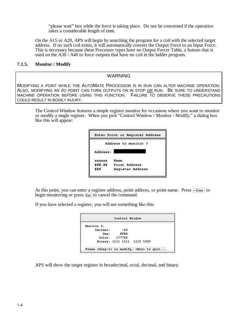
7-4
“please wait” box while the force is taking place. Do not be concerned if the operation takes a considerable length of time.
On the A15 or A20, APS will begin by searching the program for a coil with the selected target address. If no such coil exists, it will automatically convert the Output Force to an Input Force. This is necessary because these Processor types have no Output Forcer Table, a feature that is used on the A30 / A40 to force outputs that have no coil in the ladder program.
7.1.5. Monitor / Modify
WARNING
MODIFYING A POINT WHILE THE AUTOMATE PROCESSOR IS IN RUN CAN ALTER MACHINE OPERATION. ALSO, MODIFYING AN I/O POINT CAN TURN OUTPUTS ON IN STOP OR RUN. BE SURE TO UNDERSTAND MACHINE OPERATION BEFORE USING THIS FUNCTION. FAILURE TO OBSERVE THESE PRECAUTIONS COULD RESULT IN BODILY INJURY.
The Control Window features a simple register monitor for occasions where you want to monitor or modify a single register. When you pick “Control Window / Monitor / Modify,” a dialog box like this will appear:
Enter Point or Register Address
Address to monitor ? Address: xxxxxx Name ###.## Point Address ### Register Address
At this point, you can enter a register address, point address, or point name. Press r to begin monitoring or press q to cancel the command.
If you have selected a register, you will see something like this:
Control Window
Monitor 0: Decimal: -24 Hex: FFE8 Octal: 177750 Binary: 1111 1111 1110 1000 Press <Grey-+> to modify, <Esc> to quit...
APS will show the target register in hexadecimal, octal, decimal, and binary.
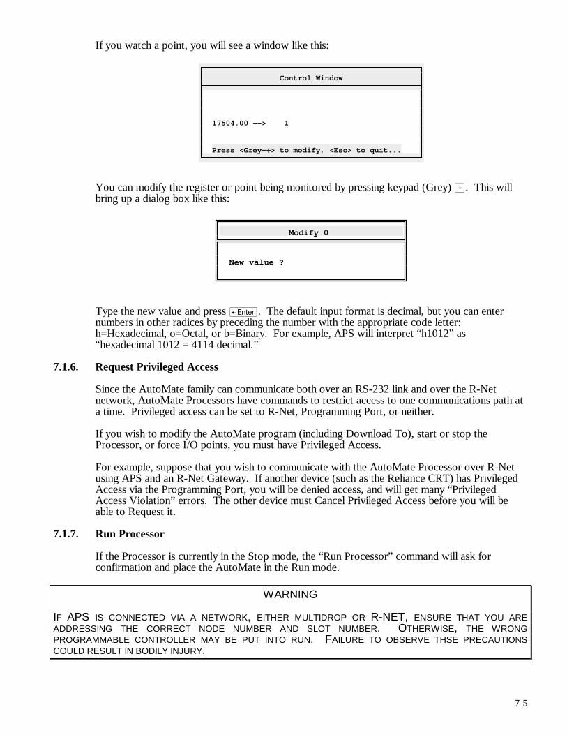
7-5
If you watch a point, you will see a window like this:
Control Window
17504.00 --> 1 Press <Grey-+> to modify, <Esc> to quit...
You can modify the register or point being monitored by pressing keypad (Grey) >. This will bring up a dialog box like this:
Modify 0
New value ?
Type the new value and press r. The default input format is decimal, but you can enter numbers in other radices by preceding the number with the appropriate code letter: h=Hexadecimal, o=Octal, or b=Binary. For example, APS will interpret “h1012” as “hexadecimal 1012 = 4114 decimal.”
7.1.6. Request Privileged Access
Since the AutoMate family can communicate both over an RS-232 link and over the R-Net network, AutoMate Processors have commands to restrict access to one communications path at a time. Privileged access can be set to R-Net, Programming Port, or neither.
If you wish to modify the AutoMate program (including Download To), start or stop the Processor, or force I/O points, you must have Privileged Access.
For example, suppose that you wish to communicate with the AutoMate Processor over R-Net using APS and an R-Net Gateway. If another device (such as the Reliance CRT) has Privileged Access via the Programming Port, you will be denied access, and will get many “Privileged Access Violation” errors. The other device must Cancel Privileged Access before you will be able to Request it.
7.1.7. Run Processor
If the Processor is currently in the Stop mode, the “Run Processor” command will ask for confirmation and place the AutoMate in the Run mode.
WARNING
IF APS IS CONNECTED VIA A NETWORK, EITHER MULTIDROP OR R-NET, ENSURE THAT YOU ARE ADDRESSING THE CORRECT NODE NUMBER AND SLOT NUMBER. OTHERWISE, THE WRONG PROGRAMMABLE CONTROLLER MAY BE PUT INTO RUN. FAILURE TO OBSERVE THSE PRECAUTIONS COULD RESULT IN BODILY INJURY.
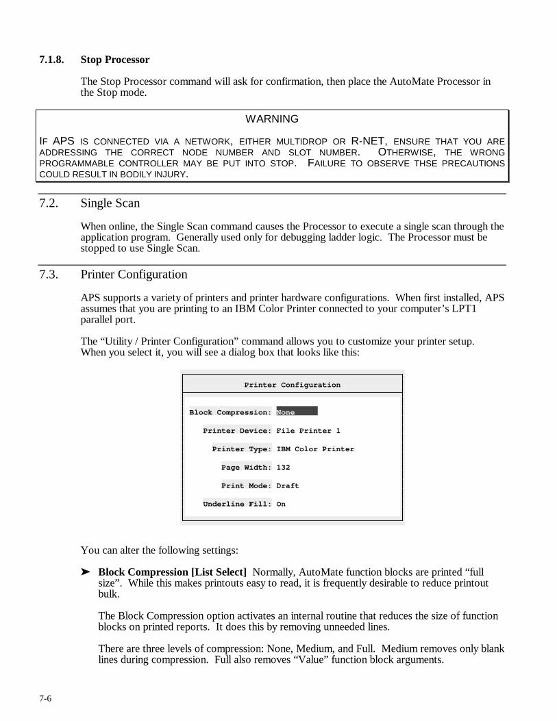
7-6
7.1.8. Stop Processor
The Stop Processor command will ask for confirmation, then place the AutoMate Processor in the Stop mode.
WARNING
IF APS IS CONNECTED VIA A NETWORK, EITHER MULTIDROP OR R-NET, ENSURE THAT YOU ARE ADDRESSING THE CORRECT NODE NUMBER AND SLOT NUMBER. OTHERWISE, THE WRONG PROGRAMMABLE CONTROLLER MAY BE PUT INTO STOP. FAILURE TO OBSERVE THSE PRECAUTIONS COULD RESULT IN BODILY INJURY.
7.2. Single Scan
When online, the Single Scan command causes the Processor to execute a single scan through the application program. Generally used only for debugging ladder logic. The Processor must be stopped to use Single Scan.
7.3. Printer Configuration
APS supports a variety of printers and printer hardware configurations. When first installed, APS assumes that you are printing to an IBM Color Printer connected to your computer’s LPT1 parallel port.
The “Utility / Printer Configuration” command allows you to customize your printer setup. When you select it, you will see a dialog box that looks like this:
Printer Configuration
Block Compression: None Printer Device: File Printer 1 Printer Type: IBM Color Printer Page Width: 132 Print Mode: Draft Underline Fill: On
You can alter the following settings:
➤ Block Compression [List Select] Normally, AutoMate function blocks are printed “full size”. While this makes printouts easy to read, it is frequently desirable to reduce printout bulk.
The Block Compression option activates an internal routine that reduces the size of function blocks on printed reports. It does this by removing unneeded lines.
There are three levels of compression: None, Medium, and Full. Medium removes only blank lines during compression. Full also removes “Value” function block arguments.
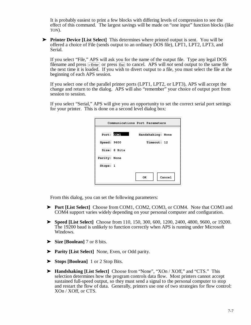
7-7
It is probably easiest to print a few blocks with differing levels of compression to see the effect of this command. The largest savings will be made on “one input” function blocks (like TON).
➤ Printer Device [List Select] This determines where printed output is sent. You will be offered a choice of File (sends output to an ordinary DOS file), LPT1, LPT2, LPT3, and Serial.
If you select “File,” APS will ask you for the name of the output file. Type any legal DOS filename and press r or press q to cancel. APS will not send output to the same file the next time it is loaded. If you wish to divert output to a file, you must select the file at the beginning of each APS session.
If you select one of the parallel printer ports (LPT1, LPT2, or LPT3), APS will accept the change and return to the dialog. APS will also “remember” your choice of output port from session to session.
If you select “Serial,” APS will give you an opportunity to set the correct serial port settings for your printer. This is done on a second level dialog box:
Communications Port Parameters
Port: COM1 Handshaking: None Speed: 9600 Timeout: 12 Size: 8 Bits Parity: None Stops: 1 OK Cancel
From this dialog, you can set the following parameters:
➤ Port [List Select] Choose from COM1, COM2, COM3, or COM4. Note that COM3 and COM4 support varies widely depending on your personal computer and configuration.
➤ Speed [List Select] Choose from 110, 150, 300, 600, 1200, 2400, 4800, 9600, or 19200. The 19200 baud is unlikely to function correctly when APS is running under Microsoft Windows.
➤ Size [Boolean] 7 or 8 bits.
➤ Parity [List Select] None, Even, or Odd parity.
➤ Stops [Boolean] 1 or 2 Stop Bits.
➤ Handshaking [List Select] Choose from “None”, “XOn / XOff,” and “CTS.” This selection determines how the program controls data flow. Most printers cannot accept sustained full-speed output, so they must send a signal to the personal computer to stop and restart the flow of data. Generally, printers use one of two strategies for flow control: XOn / XOff, or CTS.
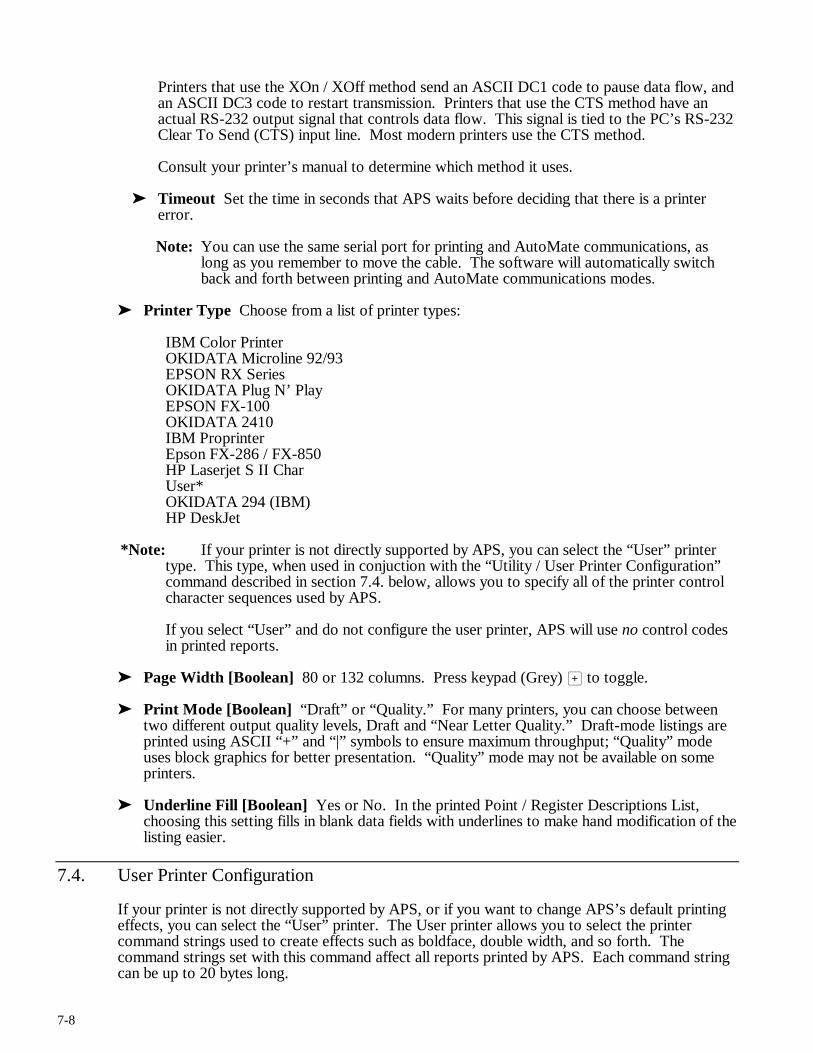
7-8
Printers that use the XOn / XOff method send an ASCII DC1 code to pause data flow, and an ASCII DC3 code to restart transmission. Printers that use the CTS method have an actual RS-232 output signal that controls data flow. This signal is tied to the PC’s RS-232 Clear To Send (CTS) input line. Most modern printers use the CTS method.
Consult your printer’s manual to determine which method it uses.
➤ Timeout Set the time in seconds that APS waits before deciding that there is a printer error.
Note: You can use the same serial port for printing and AutoMate communications, as long as you remember to move the cable. The software will automatically switch back and forth between printing and AutoMate communications modes.
➤ Printer Type Choose from a list of printer types:
IBM Color Printer OKIDATA Microline 92/93 EPSON RX Series OKIDATA Plug N’ Play EPSON FX-100 OKIDATA 2410 IBM Proprinter Epson FX-286 / FX-850 HP Laserjet S II Char User* OKIDATA 294 (IBM) HP DeskJet
*Note: If your printer is not directly supported by APS, you can select the “User” printer type. This type, when used in conjuction with the “Utility / User Printer Configuration” command described in section 7.4. below, allows you to specify all of the printer control character sequences used by APS.
If you select “User” and do not configure the user printer, APS will use no control codes in printed reports.
➤ Page Width [Boolean] 80 or 132 columns. Press keypad (Grey) > to toggle.
➤ Print Mode [Boolean] “Draft” or “Quality.” For many printers, you can choose between two different output quality levels, Draft and “Near Letter Quality.” Draft-mode listings are printed using ASCII “+” and “|” symbols to ensure maximum throughput; “Quality” mode uses block graphics for better presentation. “Quality” mode may not be available on some printers.
➤ Underline Fill [Boolean] Yes or No. In the printed Point / Register Descriptions List, choosing this setting fills in blank data fields with underlines to make hand modification of the listing easier.
7.4. User Printer Configuration
If your printer is not directly supported by APS, or if you want to change APS’s default printing effects, you can select the “User” printer. The User printer allows you to select the printer command strings used to create effects such as boldface, double width, and so forth. The command strings set with this command affect all reports printed by APS. Each command string can be up to 20 bytes long.
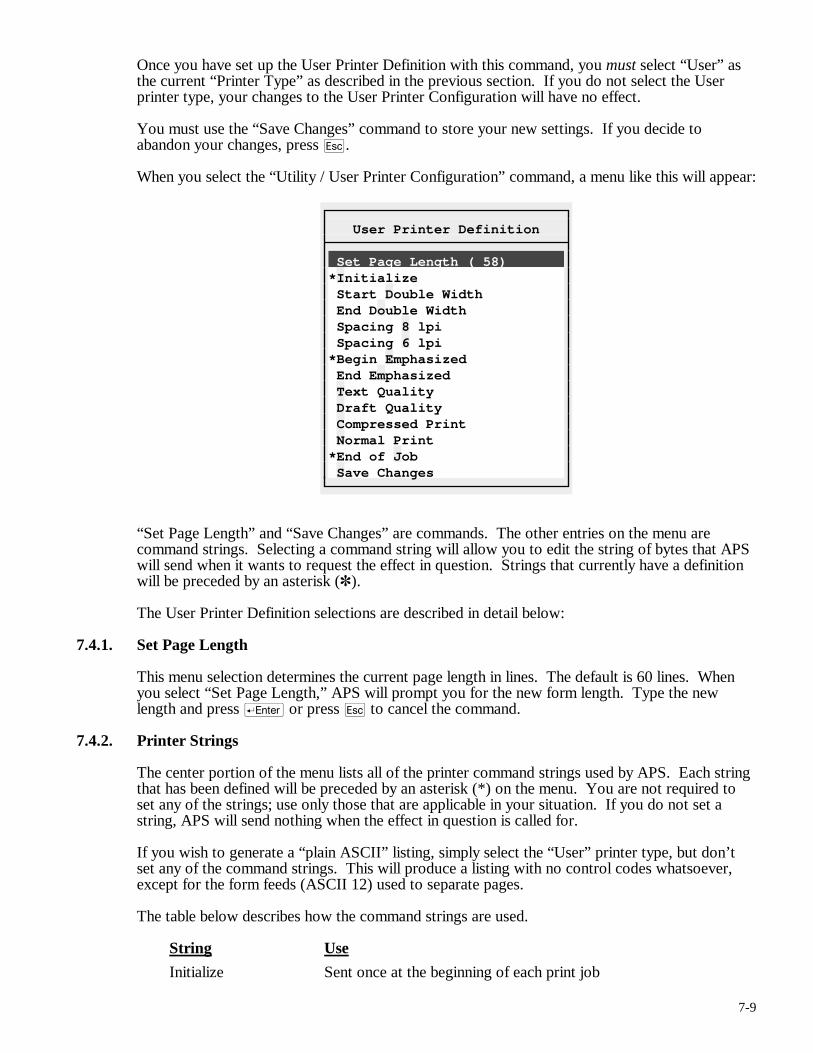
7-9
Once you have set up the User Printer Definition with this command, you must select “User” as the current “Printer Type” as described in the previous section. If you do not select the User printer type, your changes to the User Printer Configuration will have no effect.
You must use the “Save Changes” command to store your new settings. If you decide to abandon your changes, press q.
When you select the “Utility / User Printer Configuration” command, a menu like this will appear:
User Printer Definition
Set Page Length ( 58) *Initialize Start Double Width End Double Width Spacing 8 lpi Spacing 6 lpi *Begin Emphasized End Emphasized Text Quality Draft Quality Compressed Print Normal Print *End of Job Save Changes
“Set Page Length” and “Save Changes” are commands. The other entries on the menu are command strings. Selecting a command string will allow you to edit the string of bytes that APS will send when it wants to request the effect in question. Strings that currently have a definition will be preceded by an asterisk (✽).
The User Printer Definition selections are described in detail below:
7.4.1. Set Page Length
This menu selection determines the current page length in lines. The default is 60 lines. When you select “Set Page Length,” APS will prompt you for the new form length. Type the new length and press r or press q to cancel the command.
7.4.2. Printer Strings
The center portion of the menu lists all of the printer command strings used by APS. Each string that has been defined will be preceded by an asterisk (*) on the menu. You are not required to set any of the strings; use only those that are applicable in your situation. If you do not set a string, APS will send nothing when the effect in question is called for.
If you wish to generate a “plain ASCII” listing, simply select the “User” printer type, but don’t set any of the command strings. This will produce a listing with no control codes whatsoever, except for the form feeds (ASCII 12) used to separate pages.
The table below describes how the command strings are used.
String Use
Initialize Sent once at the beginning of each print job
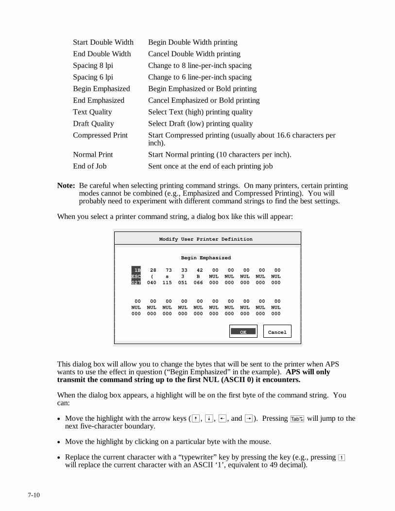
7-10
Start Double Width Begin Double Width printing
End Double Width Cancel Double Width printing
Spacing 8 lpi Change to 8 line-per-inch spacing
Spacing 6 lpi Change to 6 line-per-inch spacing
Begin Emphasized Begin Emphasized or Bold printing
End Emphasized Cancel Emphasized or Bold printing
Text Quality Select Text (high) printing quality
Draft Quality Select Draft (low) printing quality
Compressed Print Start Compressed printing (usually about 16.6 characters per inch).
Normal Print Start Normal printing (10 characters per inch).
End of Job Sent once at the end of each printing job
Note: Be careful when selecting printing command strings. On many printers, certain printing modes cannot be combined (e.g., Emphasized and Compressed Printing). You will probably need to experiment with different command strings to find the best settings.
When you select a printer command string, a dialog box like this will appear:
Modify User Printer Definition
Begin Emphasized 1B 28 73 33 42 00 00 00 00 00 ESC ( s 3 B NUL NUL NUL NUL NUL 027 040 115 051 066 000 000 000 000 000 00 00 00 00 00 00 00 00 00 00 NUL NUL NUL NUL NUL NUL NUL NUL NUL NUL 000 000 000 000 000 000 000 000 000 000 OK Cancel
This dialog box will allow you to change the bytes that will be sent to the printer when APS wants to use the effect in question (“Begin Emphasized” in the example). APS will only transmit the command string up to the first NUL (ASCII 0) it encounters.
When the dialog box appears, a highlight will be on the first byte of the command string. You can:
• Move the highlight with the arrow keys (ß, Í, ®, and Â). Pressing t will jump to the next five-character boundary.
• Move the highlight by clicking on a particular byte with the mouse.
• Replace the current character with a “typewriter” key by pressing the key (e.g., pressing 1 will replace the current character with an ASCII ‘1’, equivalent to 49 decimal).
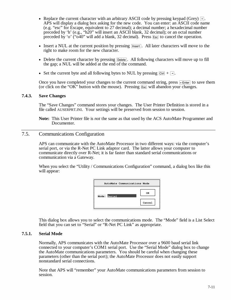
7-11
• Replace the current character with an arbitrary ASCII code by pressing keypad (Grey) >. APS will display a dialog box asking for the new code. You can enter: an ASCII code name (e.g. “esc” for Escape, equivalent to 27 decimal); a decimal number; a hexadecimal number preceded by ‘h’ (e.g., “h20” will insert an ASCII blank, 32 decimal); or an octal number preceded by ‘o’ (“o40” will add a blank, 32 decimal). Press q to cancel the operation.
• Insert a NUL at the current position by pressing i. All later characters will move to the right to make room for the new character.
• Delete the current character by pressing d. All following characters will move up to fill the gap; a NUL will be added at the end of the command.
• Set the current byte and all following bytes to NUL by pressing c + Â.
Once you have completed your changes to the current command string, press r to save them (or click on the “OK” button with the mouse). Pressing q will abandon your changes.
7.4.3. Save Changes
The “Save Changes” command stores your changes. The User Printer Definition is stored in a file called AUSERPRT.INI. Your settings will be preserved from session to session.
Note: This User Printer file is not the same as that used by the ACS AutoMate Programmer and Documenter.
7.5. Communications Configuration
APS can communicate with the AutoMate Processor in two different ways: via the computer’s serial port, or via the R-Net PC Link adaptor card. The latter allows your computer to communicate directly over R-Net; it is far faster than standard serial communications or communication via a Gateway.
When you select the “Utility / Communications Configuration” command, a dialog box like this will appear:
AutoMate Communications Mode
OK Mode: Serial Cancel
This dialog box allows you to select the communications mode. The “Mode” field is a List Select field that you can set to “Serial” or “R-Net PC Link” as appropriate.
7.5.1. Serial Mode
Normally, APS communicates with the AutoMate Processor over a 9600 baud serial link connected to your computer’s COM1 serial port. Use the “Serial Mode” dialog box to change the AutoMate communications parameters. You should be careful when changing these parameters (other than the serial port); the AutoMate Processor does not easily support nonstandard serial connections.
Note that APS will “remember” your AutoMate communications parameters from session to session.
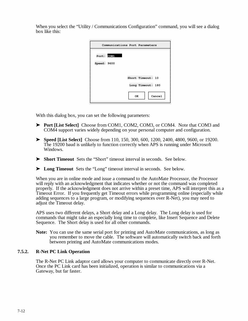
7-12
When you select the “Utility / Communications Configuration” command, you will see a dialog box like this:
Communications Port Parameters
Port: COM1 Speed: 9600 Short Timeout: 10 Long Timeout: 180 OK Cancel
With this dialog box, you can set the following parameters:
➤ Port [List Select] Choose from COM1, COM2, COM3, or COM4. Note that COM3 and COM4 support varies widely depending on your personal computer and configuration.
➤ Speed [List Select] Choose from 110, 150, 300, 600, 1200, 2400, 4800, 9600, or 19200. The 19200 baud is unlikely to function correctly when APS is running under Microsoft Windows.
➤ Short Timeout Sets the “Short” timeout interval in seconds. See below.
➤ Long Timeout Sets the “Long” timeout interval in seconds. See below.
When you are in online mode and issue a command to the AutoMate Processor, the Processor will reply with an acknowledgment that indicates whether or not the command was completed properly. If the acknowledgment does not arrive within a preset time, APS will interpret this as a Timeout Error. If you frequently get Timeout errors while programming online (especially while adding sequences to a large program, or modifying sequences over R-Net), you may need to adjust the Timeout delay.
APS uses two different delays, a Short delay and a Long delay. The Long delay is used for commands that might take an especially long time to complete, like Insert Sequence and Delete Sequence. The Short delay is used for all other commands.
Note: You can use the same serial port for printing and AutoMate communications, as long as you remember to move the cable. The software will automatically switch back and forth between printing and AutoMate communications modes.
7.5.2. R-Net PC Link Operation
The R-Net PC Link adaptor card allows your computer to communicate directly over R-Net. Once the PC Link card has been initialized, operation is similar to communications via a Gateway, but far faster.
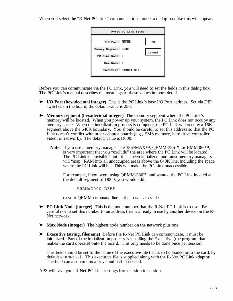
7-13
When you select the “R-Net PC Link” communications mode, a dialog box like this will appear:
R-Net PC Link Setup
I/O Port: 250 OK Memory Segment: d000 Cancel PC Link Node: 0 Max Node: 5 Executive: RTRNET.SS1
Before you can communicate via the PC Link, you will need to set the fields in this dialog box. The PC Link’s manual describes the meanings of these values in more detail.
➤ I/O Port (hexadecimal integer) This is the PC Link’s base I/O Port address. Set via DIP switches on the board, the default value is 250.
➤ Memory segment (hexadecimal integer) The memory segment where the PC Link’s memory will be located. When you power up your system, the PC Link does not occupy any memory space. When the initialization process is complete, the PC Link will occupy a 16K segment above the 640K boundary. You should be careful to set this address so that the PC Link doesn’t conflict with other adaptor boards (e.g., EMS memory, hard drive controller, video, or network). The default value is D000.
Note: If you use a memory manager like 386^MAX™, QEMM-386™, or EMM386™, it is very important that you “exclude” the area where the PC Link will be located. The PC Link is “invisible” until it has been initialized, and most memory managers will “map” RAM into all unoccupied areas above the 640K line, including the space where the PC Link will be. This will make the PC Link unaccessible.
For example, if you were using QEMM-386™ and wanted the PC Link located at the default segment of D000, you would add:
ARAM=D000-D3FF
to your QEMM command line in the CONFIG.SYS file.
➤ PC Link Node (integer) This is the node number that the R-Net PC Link is to use. Be careful not to set this number to an address that is already in use by another device on the R-Net network.
➤ Max Node (integer) The highest node number on the network plus one.
➤ Executive (string, filename) Before the R-Net PC Link can communicate, it must be initialized. Part of the initialization process is installing the Executive (the program that makes the card operate) onto the board. This only needs to be done once per session.
This field should be set to the name of the executive file that is to be loaded onto the card, by default RTRNET.SS1. This executive file is supplied along with the R-Net PC Link adaptor. The field can also contain a drive and path if needed.
APS will save your R-Net PC Link settings from session to session.
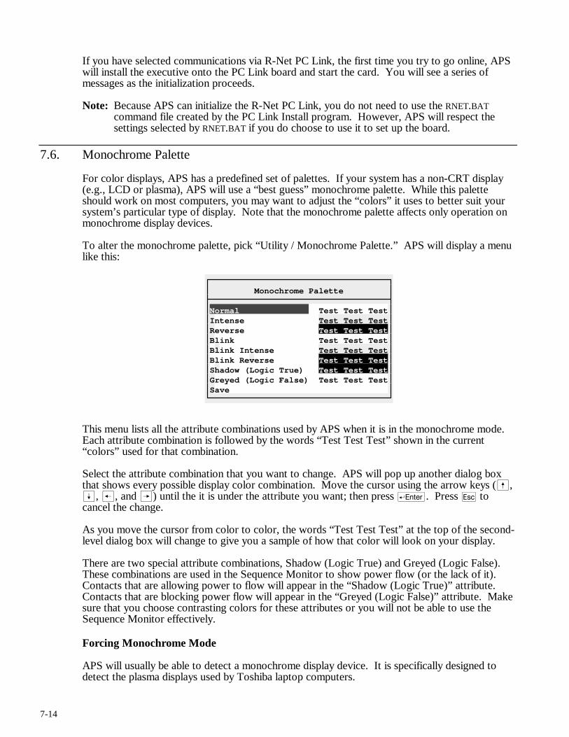
7-14
If you have selected communications via R-Net PC Link, the first time you try to go online, APS will install the executive onto the PC Link board and start the card. You will see a series of messages as the initialization proceeds.
Note: Because APS can initialize the R-Net PC Link, you do not need to use the RNET.BAT command file created by the PC Link Install program. However, APS will respect the settings selected by RNET.BAT if you do choose to use it to set up the board.
7.6. Monochrome Palette
For color displays, APS has a predefined set of palettes. If your system has a non-CRT display (e.g., LCD or plasma), APS will use a “best guess” monochrome palette. While this palette should work on most computers, you may want to adjust the “colors” it uses to better suit your system’s particular type of display. Note that the monochrome palette affects only operation on monochrome display devices.
To alter the monochrome palette, pick “Utility / Monochrome Palette.” APS will display a menu like this:
Monochrome Palette
Normal Test Test TestIntense Test Test TestReverse Test Test TestBlink Test Test TestBlink Intense Test Test TestBlink Reverse Test Test TestShadow (Logic True) Test Test TestGreyed (Logic False) Test Test TestSave
This menu lists all the attribute combinations used by APS when it is in the monochrome mode. Each attribute combination is followed by the words “Test Test Test” shown in the current “colors” used for that combination.
Select the attribute combination that you want to change. APS will pop up another dialog box that shows every possible display color combination. Move the cursor using the arrow keys (ß, Í, ®, and Â) until the it is under the attribute you want; then press r. Press q to cancel the change.
As you move the cursor from color to color, the words “Test Test Test” at the top of the second-level dialog box will change to give you a sample of how that color will look on your display.
There are two special attribute combinations, Shadow (Logic True) and Greyed (Logic False). These combinations are used in the Sequence Monitor to show power flow (or the lack of it). Contacts that are allowing power to flow will appear in the “Shadow (Logic True)” attribute. Contacts that are blocking power flow will appear in the “Greyed (Logic False)” attribute. Make sure that you choose contrasting colors for these attributes or you will not be able to use the Sequence Monitor effectively.
Forcing Monochrome Mode
APS will usually be able to detect a monochrome display device. It is specifically designed to detect the plasma displays used by Toshiba laptop computers.
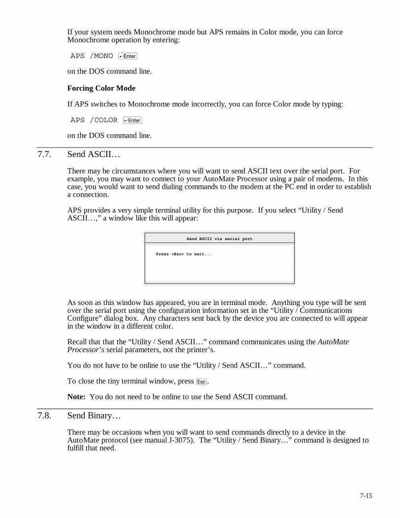
7-15
If your system needs Monochrome mode but APS remains in Color mode, you can force Monochrome operation by entering:
APS /MONO r
on the DOS command line.
Forcing Color Mode
If APS switches to Monochrome mode incorrectly, you can force Color mode by typing:
APS /COLOR r
on the DOS command line.
7.7. Send ASCII…
There may be circumstances where you will want to send ASCII text over the serial port. For example, you may want to connect to your AutoMate Processor using a pair of modems. In this case, you would want to send dialing commands to the modem at the PC end in order to establish a connection.
APS provides a very simple terminal utility for this purpose. If you select “Utility / Send ASCII…,” a window like this will appear:
Send ASCII via serial port
Press <Esc> to exit...
As soon as this window has appeared, you are in terminal mode. Anything you type will be sent over the serial port using the configuration information set in the “Utility / Communications Configure” dialog box. Any characters sent back by the device you are connected to will appear in the window in a different color.
Recall that that the “Utility / Send ASCII…” command communicates using the AutoMate Processor’s serial parameters, not the printer’s.
You do not have to be online to use the “Utility / Send ASCII…” command.
To close the tiny terminal window, press q.
Note: You do not need to be online to use the Send ASCII command.
7.8. Send Binary…
There may be occasions when you will want to send commands directly to a device in the AutoMate protocol (see manual J-3075). The “Utility / Send Binary…” command is designed to fulfill that need.
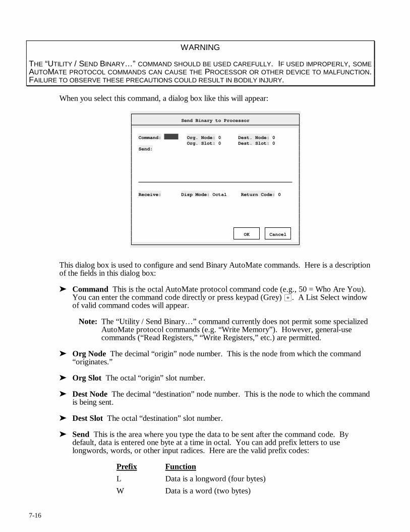
7-16
WARNING
THE “UTILITY / SEND BINARY…” COMMAND SHOULD BE USED CAREFULLY. IF USED IMPROPERLY, SOME AUTOMATE PROTOCOL COMMANDS CAN CAUSE THE PROCESSOR OR OTHER DEVICE TO MALFUNCTION. FAILURE TO OBSERVE THESE PRECAUTIONS COULD RESULT IN BODILY INJURY.
When you select this command, a dialog box like this will appear:
Send Binary to Processor
Command: Org. Node: 0 Dest. Node: 0 Org. Slot: 0 Dest. Slot: 0 Send: Receive: Disp Mode: Octal Return Code: 0 OK Cancel
This dialog box is used to configure and send Binary AutoMate commands. Here is a description of the fields in this dialog box:
➤ Command This is the octal AutoMate protocol command code (e.g., 50 = Who Are You). You can enter the command code directly or press keypad (Grey) >. A List Select window of valid command codes will appear.
Note: The “Utility / Send Binary…” command currently does not permit some specialized AutoMate protocol commands (e.g. “Write Memory”). However, general-use commands (“Read Registers,” “Write Registers,” etc.) are permitted.
➤ Org Node The decimal “origin” node number. This is the node from which the command “originates.”
➤ Org Slot The octal “origin” slot number.
➤ Dest Node The decimal “destination” node number. This is the node to which the command is being sent.
➤ Dest Slot The octal “destination” slot number.
➤ Send This is the area where you type the data to be sent after the command code. By default, data is entered one byte at a time in octal. You can add prefix letters to use longwords, words, or other input radices. Here are the valid prefix codes:
Prefix Function
L Data is a longword (four bytes)
W Data is a word (two bytes)
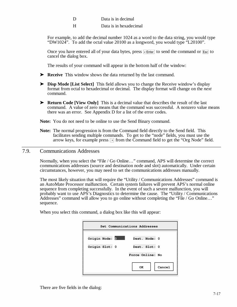
7-17
D Data is in decimal
H Data is in hexadecimal
For example, to add the decimal number 1024 as a word to the data string, you would type “DW1024”. To add the octal value 20100 as a longword, you would type “L20100”.
Once you have entered all of your data bytes, press r to send the command or q to cancel the dialog box.
The results of your command will appear in the bottom half of the window:
➤ Receive This window shows the data returned by the last command.
➤ Disp Mode [List Select] This field allows you to change the Receive window’s display format from octal to hexadecimal or decimal. The display format will change on the next command.
➤ Return Code [View Only] This is a decimal value that describes the result of the last command. A value of zero means that the command was successful. A nonzero value means there was an error. See Appendix D for a list of the error codes.
Note: You do not need to be online to use the Send Binary command.
Note: The normal progression is from the Command field directly to the Send field. This facilitates sending multiple commands. To get to the “node” fields, you must use the arrow keys, for example press  from the Command field to get the “Org Node” field.
7.9. Communications Addresses
Normally, when you select the “File / Go Online…” command, APS will determine the correct communications addresses (source and destination node and slot) automatically. Under certain circumstances, however, you may need to set the communications addresses manually.
The most likely situation that will require the “Utility / Communications Addresses” command is an AutoMate Processor malfunction. Certain system failures will prevent APS’s normal online sequence from completing successfully. In the event of such a severe malfunction, you will probably want to use APS’s Diagnostics to determine the cause. The “Utility / Communications Addresses” command will allow you to go online without completing the “File / Go Online…” sequence.
When you select this command, a dialog box like this will appear:
Set Communications Addresses
Origin Node: 0 Dest. Node: 0 Origin Slot: 0 Dest. Slot: 0 Force Online: No OK Cancel
There are five fields in the dialog:
7-18
➤ Origin Node This is the computer’s node number, from 0 to 254 decimal.
➤ Origin Slot The computer’s “slot” number, from 0 to 20 octal.
➤ Dest. Node The AutoMate Processor’s node number from 0 to 254. If you are connecting to the Processor through its Programming Port, this number should be zero.
➤ Dest. Slot The AutoMate Processor’s slot number, from 0 to 20 octal.
➤ Force Online [Boolean] Yes or No. Determines if APS will set the online flag when you complete the dialog box. This will place APS in the online mode without going through the tests used by the “File / Online…” command. Once you have Forced Online mode, you will be able to use the Diagnostics to examine the Processor.
The “Force Online” option may be the only way to get online if the usual “File / Go Online…” command does not work.
Note: An AutoMate malfunction serious enough to prevent APS from going online normally may also prevent some monitoring features (such as the Register Monitor) from working properly. You should not attempt to edit the application program or change registers until the Processor has been reset by cycling the power to the rack. Once power has been restored, clear the Processor’s memory (“Utility / Auxiliary…”) and download the program to the Processor.
For most situations, all four numeric fields may be set to zero (as long as you are connected to the AutoMate Processor’s Programming Port). If you are trying to connect over R-Net, you will have to set the correct destination node and slot values.
Once you have set the correct values, press r to accept them or q to cancel the command. If you have elected to “Force Online,” APS will ask for confirmation before completing the command.
Going online in this way is called “Forcing Online” since you are connecting to the AutoMate Processor without the usual tests performed by the “File / Go Online…” command.
Note that Forcing Online will only work if the connection to the Processor is basically sound. In other words, use Force Online if the “File / Go Online…” gives a processor error, especially “Error 61.” Communications errors, such as “Timeout” and “Checksum Error” will not be prevented by the Force Online command; these are symptoms of a fault in the connection between your computer and the AutoMate processor.
7.10. Register Limit…
Use the Register Limit command to alter the Data Register Limit on A20E or higher AutoMate Processors. The Data Register Limit determines how many registers above the address 20000 are available. This APS command can be used online or offline.
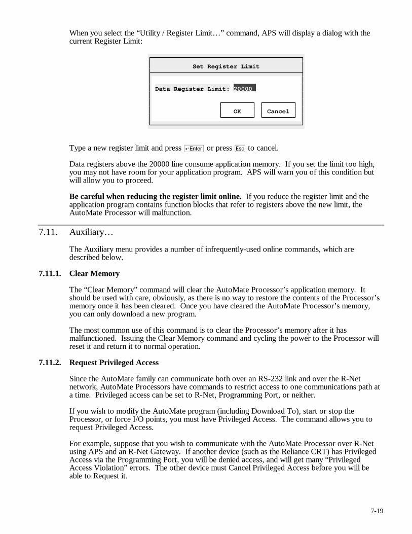
7-19
When you select the “Utility / Register Limit…” command, APS will display a dialog with the current Register Limit:
Set Register Limit
Data Register Limit: 20000 OK Cancel
Type a new register limit and press r or press q to cancel.
Data registers above the 20000 line consume application memory. If you set the limit too high, you may not have room for your application program. APS will warn you of this condition but will allow you to proceed.
Be careful when reducing the register limit online. If you reduce the register limit and the application program contains function blocks that refer to registers above the new limit, the AutoMate Processor will malfunction.
7.11. Auxiliary…
The Auxiliary menu provides a number of infrequently-used online commands, which are described below.
7.11.1. Clear Memory
The “Clear Memory” command will clear the AutoMate Processor’s application memory. It should be used with care, obviously, as there is no way to restore the contents of the Processor’s memory once it has been cleared. Once you have cleared the AutoMate Processor’s memory, you can only download a new program.
The most common use of this command is to clear the Processor’s memory after it has malfunctioned. Issuing the Clear Memory command and cycling the power to the Processor will reset it and return it to normal operation.
7.11.2. Request Privileged Access
Since the AutoMate family can communicate both over an RS-232 link and over the R-Net network, AutoMate Processors have commands to restrict access to one communications path at a time. Privileged access can be set to R-Net, Programming Port, or neither.
If you wish to modify the AutoMate program (including Download To), start or stop the Processor, or force I/O points, you must have Privileged Access. The command allows you to request Privileged Access.
For example, suppose that you wish to communicate with the AutoMate Processor over R-Net using APS and an R-Net Gateway. If another device (such as the Reliance CRT) has Privileged Access via the Programming Port, you will be denied access, and will get many “Privileged Access Violation” errors. The other device must Cancel Privileged Access before you will be able to Request it.
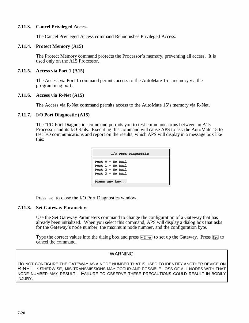
7-20
7.11.3. Cancel Privileged Access
The Cancel Privileged Access command Relinquishes Privileged Access.
7.11.4. Protect Memory (A15)
The Protect Memory command protects the Processor’s memory, preventing all access. It is used only on the A15 Processor.
7.11.5. Access via Port 1 (A15)
The Access via Port 1 command permits access to the AutoMate 15’s memory via the programming port.
7.11.6. Access via R-Net (A15)
The Access via R-Net command permits access to the AutoMate 15’s memory via R-Net.
7.11.7. I/O Port Diagnostic (A15)
The “I/O Port Diagnostic” command permits you to test communications between an A15 Processor and its I/O Rails. Executing this command will cause APS to ask the AutoMate 15 to test I/O communications and report on the results, which APS will display in a message box like this:
I/O Port Diagnostic
Port 0 - No Rail Port 1 - No Rail Port 2 - No Rail Port 3 - No Rail Press any key...
Press q to close the I/O Port Diagnostics window.
7.11.8. Set Gateway Parameters
Use the Set Gateway Parameters command to change the configuration of a Gateway that has already been initialized. When you select this command, APS will display a dialog box that asks for the Gateway’s node number, the maximum node number, and the configuration byte.
Type the correct values into the dialog box and press r to set up the Gateway. Press q to cancel the command.
WARNING
DO NOT CONFIGURE THE GATEWAY AS A NODE NUMBER THAT IS USED TO IDENTIFY ANOTHER DEVICE ON R-NET. OTHERWISE, MIS-TRANSMISSIONS MAY OCCUR AND POSSIBLE LOSS OF ALL NODES WITH THAT NODE NUMBER MAY RESULT. FAILURE TO OBSERVE THESE PRECAUTIONS COULD RESULT IN BODILY INJURY.
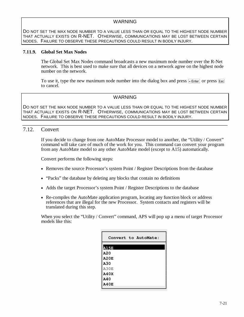
7-21
WARNING
DO NOT SET THE MAX NODE NUMBER TO A VALUE LESS THAN OR EQUAL TO THE HIGHEST NODE NUMBER THAT ACTUALLY EXISTS ON R-NET. OTHERWISE, COMMUNICATIONS MAY BE LOST BETWEEN CERTAIN NODES. FAILURE TO OBSERVE THESE PRECAUTIONS COULD RESULT IN BODILY INJURY.
7.11.9. Global Set Max Nodes
The Global Set Max Nodes command broadcasts a new maximum node number over the R-Net network. This is best used to make sure that all devices on a network agree on the highest node number on the network.
To use it, type the new maximum node number into the dialog box and press r or press q to cancel.
WARNING
DO NOT SET THE MAX NODE NUMBER TO A VALUE LESS THAN OR EQUAL TO THE HIGHEST NODE NUMBER THAT ACTUALLY EXISTS ON R-NET. OTHERWISE, COMMUNICATIONS MAY BE LOST BETWEEN CERTAIN NODES. FAILURE TO OBSERVE THESE PRECAUTIONS COULD RESULT IN BODILY INJURY.
7.12. Convert
If you decide to change from one AutoMate Processor model to another, the “Utility / Convert” command will take care of much of the work for you. This command can convert your program from any AutoMate model to any other AutoMate model (except to A15) automatically.
Convert performs the following steps:
• Removes the source Processor’s system Point / Register Descriptions from the database
• “Packs” the database by deleting any blocks that contain no definitions
• Adds the target Processor’s system Point / Register Descriptions to the database
• Re-compiles the AutoMate application program, locating any function block or address references that are illegal for the new Processor. System contacts and registers will be translated during this step.
When you select the “Utility / Convert” command, APS will pop up a menu of target Processor models like this:
Convert to AutoMate:
A15E A20 A20E A30 A30E A40X A40 A40E
7-22
You will notice that the current Processor model is greyed out (no point in converting to the same model). After you select the target model and confirm, APS will begin converting the program.
If APS finds any illegal blocks or addresses in the application program, it will display a message and cancel the conversion. You must then correct the source rung and restart the conversion.
You can cancel a Convert operation by pressing q. However, it is highly likely that you will end up with something that is neither the source program nor the correct converted program. If you cancel a conversion, it is best to return to your backup copy.
Note: We strongly recommend that you back up (or make a safe copy) of an application program before converting it.
Converting A15 Programs
Converting an application program from an AutoMate 15 to another processor involves some special circumstances. First, the A15’s Function Blocks (SHR, TMR, and CTR) are not available on other AutoMate processors. Second, the A15 uses registers in the range 1000 - 1070, which are not allowed on any other Processor except the A40.
When converting from an A15 program, APS will make some adjustments to help ensure that the resulting program will be valid on the target Processor:
• SHR blocks are converted to SHBR. The table length is converted directly, but APS adds 1000 to the Elapsed register to bring it into the valid data register range.
• TMR blocks are converted to TON with a Clock value of 0.01 seconds. APS will add 1000 to the Elapsed register address.
• CTR blocks are converted to COUNTER blocks. Both the Preset and Elapsed register addresses are increased by 1000. Since COUNTER is a two-output block, APS will assign a valid coil address to the second coil beginning at 40.00.
After converting an A15 program, you should be especially careful to be sure that the result is correct. You may need to change data register values, SHBR lengths, COUNTER second-output addresses, and Preset values to ensure correct operation.
7.13. Rebuild Database
If you get “BTrieve Error” message boxes, you may need to rebuild the database. Rebuilding creates a new database from the current one. This patches up any problems with damaged records or index information in the file.
APS will ask for confirmation before it begins rebuilding. If you decide to proceed, APS will rename the current database to “projectname.BAK,” create a new project database, and perform the rebuild. If there is already a file with the name “projectname.BAK,” APS will prompt before replacing it.
APS will display a variety of information messages as it rebuilds. Most will require no action on your part. APS will also create a listing file called BCHK.LST in the current directory. This file will contain a description of any repairs that APS made during the rebuild. You may wish to examine any blocks mentioned in BCHK.LST to make sure that no data is missing.
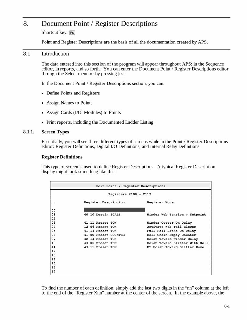
8-1
8. Document Point / Register Descriptions Shortcut key: %
Point and Register Descriptions are the basis of all the documentation created by APS.
8.1. Introduction
The data entered into this section of the program will appear throughout APS: in the Sequence editor, in reports, and so forth. You can enter the Document Point / Register Descriptions editor through the Select menu or by pressing %.
In the Document Point / Register Descriptions section, you can:
• Define Points and Registers
• Assign Names to Points
• Assign Cards (I/O Modules) to Points
• Print reports, including the Documented Ladder Listing
8.1.1. Screen Types
Essentially, you will see three different types of screens while in the Point / Register Descriptions editor: Register Definitions, Digital I/O Definitions, and Internal Relay Definitions.
Register Definitions
This type of screen is used to define Register Descriptions. A typical Register Description display might look something like this:
Edit Point / Register Descriptions
Registers 2100 - 2117 nn Register Description Register Note 00 01 40.10 Destin SCALI Winder Web Tension > Setpoint 02 03 41.11 Preset TON Winder Cutter On Delay 04 12.06 Preset TON Activate Web Tail Blower 05 41.14 Preset TON Full Roll Brake On Delay 06 41.00 Preset COUNTER Roll Chain Empty Counter 07 42.14 Preset TON Hoist Toward Winder Relay 10 43.05 Preset TON Hoist Toward Slitter With Roll 11 43.11 Preset TON MT Hoist Toward Slitter Home 12 13 14 15 16 17
To find the number of each definition, simply add the last two digits in the “nn” column at the left to the end of the “Register Xnn” number at the center of the screen. In the example above, the
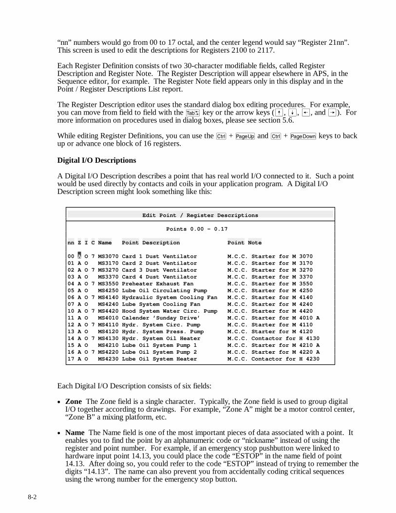
8-2
“nn” numbers would go from 00 to 17 octal, and the center legend would say “Register 21nn”. This screen is used to edit the descriptions for Registers 2100 to 2117.
Each Register Definition consists of two 30-character modifiable fields, called Register Description and Register Note. The Register Description will appear elsewhere in APS, in the Sequence editor, for example. The Register Note field appears only in this display and in the Point / Register Descriptions List report.
The Register Description editor uses the standard dialog box editing procedures. For example, you can move from field to field with the t key or the arrow keys (ß, Í, ®, and Â). For more information on procedures used in dialog boxes, please see section 5.6.
While editing Register Definitions, you can use the c + u and c + v keys to back up or advance one block of 16 registers.
Digital I/O Descriptions
A Digital I/O Description describes a point that has real world I/O connected to it. Such a point would be used directly by contacts and coils in your application program. A Digital I/O Description screen might look something like this:
Edit Point / Register Descriptions
Points 0.00 - 0.17 nn Z I C Name Point Description Point Note 00 A O 7 MS3070 Card 1 Dust Ventilator M.C.C. Starter for M 3070 01 A O MS3170 Card 2 Dust Ventilator M.C.C. Starter for M 3170 02 A O 7 MS3270 Card 3 Dust Ventilator M.C.C. Starter for M 3270 03 A O MS3370 Card 4 Dust Ventilator M.C.C. Starter for M 3370 04 A O 7 MS3550 Preheater Exhaust Fan M.C.C. Starter for M 3550 05 A O MS4250 Lube Oil Circulating Pump M.C.C. Starter for M 4250 06 A O 7 MS4140 Hydraulic System Cooling Fan M.C.C. Starter for M 4140 07 A O MS4240 Lube System Cooling Fan M.C.C. Starter for M 4240 10 A O 7 MS4420 Hood System Water Circ. Pump M.C.C. Starter for M 4420 11 A O MS4010 Calender ’Sunday Drive’ M.C.C. Starter for M 4010 A 12 A O 7 MS4110 Hydr. System Circ. Pump M.C.C. Starter for M 4110 13 A O MS4120 Hydr. System Press. Pump M.C.C. Starter for M 4120 14 A O 7 MS4130 Hydr. System Oil Heater M.C.C. Contactor for H 4130 15 A O MS4210 Lube Oil System Pump 1 M.C.C. Starter for M 4210 A 16 A O 7 MS4220 Lube Oil System Pump 2 M.C.C. Starter for M 4220 A 17 A O MS4230 Lube Oil System Heater M.C.C. Contactor for H 4230
Each Digital I/O Description consists of six fields:
• Zone The Zone field is a single character. Typically, the Zone field is used to group digital I/O together according to drawings. For example, “Zone A” might be a motor control center, “Zone B” a mixing platform, etc.
• Name The Name field is one of the most important pieces of data associated with a point. It enables you to find the point by an alphanumeric code or “nickname” instead of using the register and point number. For example, if an emergency stop pushbutton were linked to hardware input point 14.13, you could place the code “ESTOP” in the name field of point 14.13. After doing so, you could refer to the code “ESTOP” instead of trying to remember the digits “14.13”. The name can also prevent you from accidentally coding critical sequences using the wrong number for the emergency stop button.
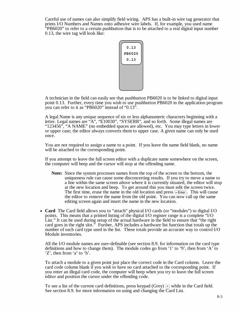
8-3
Careful use of names can also simplify field wiring. APS has a built-in wire tag generator that prints I/O Numbers and Names onto adhesive wire labels. If, for example, you used name “PB6020” to refer to a certain pushbutton that is to be attached to a real digital input number 0.13, the wire tag will look like:
0.13
PB6020
0.13
A technician in the field can easily see that pushbutton PB6020 is to be linked to digital input point 0.13. Further, every time you wish to use pushbutton PB6020 in the application program you can refer to it as “PB6020” instead of “0.13”.
A legal Name is any unique sequence of six or less alphanumeric characters beginning with a letter. Legal names are “A”, “E10030”, “SYSERR”, and so forth. Some illegal names are “123456”, “A NAME” (no embedded spaces are allowed), etc. You may type letters in lower or upper case; the editor always converts them to upper case. A given name can only be used once.
You are not required to assign a name to a point. If you leave the name field blank, no name will be attached to the corresponding point.
If you attempt to leave the full screen editor with a duplicate name somewhere on the screen, the computer will beep and the cursor will stop at the offending name.
Note: Since the system processes names from the top of the screen to the bottom, the uniqueness rule can cause some disconcerting results. If you try to move a name to a line within the same screen above where it is currently situated, the editor will stop at the new location and beep. To get around this you must edit the screen twice. The first time, erase the name in the old location and press r. This will cause the editor to remove the name from the old point. You can now call up the same editing screen again and insert the name in the new location.
• Card The Card field allows you to “attach” physical I/O cards (or “modules”) to digital I/O points. This means that a printed listing of the digital I/O register range is a complete “I/O List.” It can be used during setup of the actual hardware in the field to ensure that “the right card goes in the right slot.” Further, APS includes a hardware list function that totals up the number of each card type used in the list. These totals provide an accurate way to control I/O Module inventories.
All the I/O module names are user-definable (see section 8.9. for information on the card type definitions and how to change them). The module codes go from ‘1’ to ‘9’, then from ‘A’ to ‘Z’, then from ‘a’ to ‘h’.
To attach a module to a given point just place the correct code in the Card column. Leave the card code column blank if you wish to have no card attached to the corresponding point. If you enter an illegal card code, the computer will beep when you try to leave the full screen editor and position the cursor under the offending code.
To see a list of the current card definitions, press keypad (Grey) > while in the Card field. See section 8.9. for more information on using and changing the Card List.
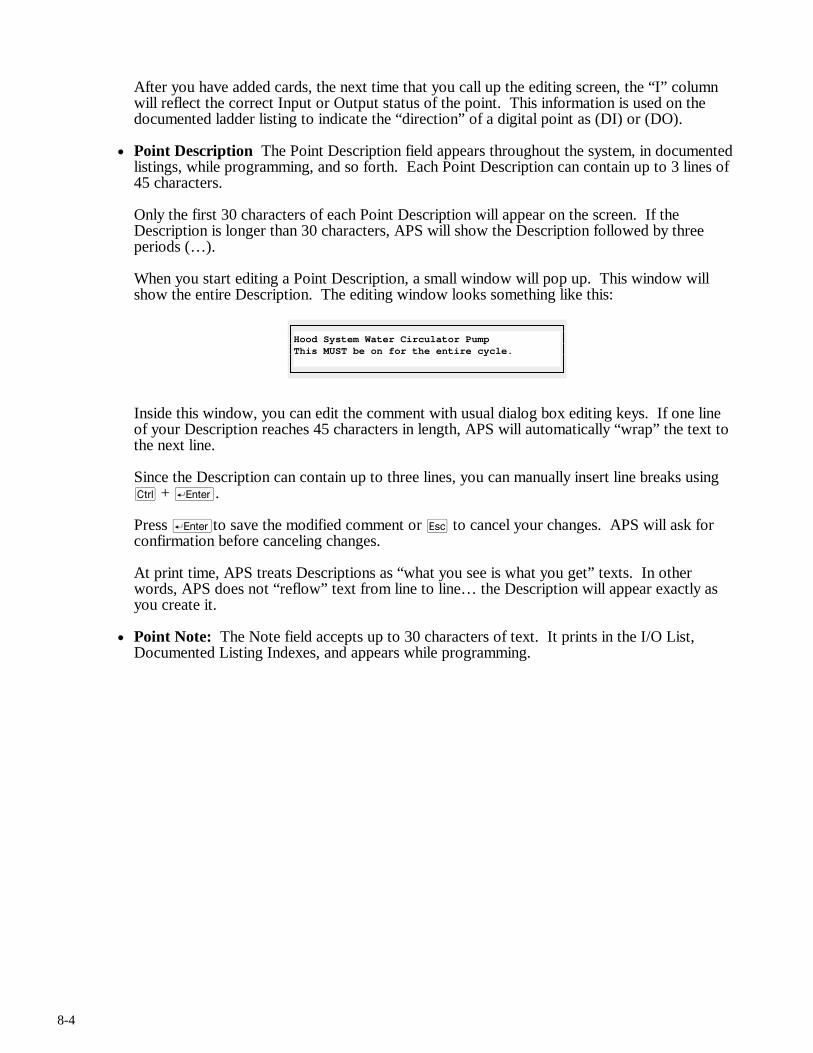
8-4
After you have added cards, the next time that you call up the editing screen, the “I” column will reflect the correct Input or Output status of the point. This information is used on the documented ladder listing to indicate the “direction” of a digital point as (DI) or (DO).
• Point Description The Point Description field appears throughout the system, in documented listings, while programming, and so forth. Each Point Description can contain up to 3 lines of 45 characters.
Only the first 30 characters of each Point Description will appear on the screen. If the Description is longer than 30 characters, APS will show the Description followed by three periods (…).
When you start editing a Point Description, a small window will pop up. This window will show the entire Description. The editing window looks something like this:
Hood System Water Circulator Pump This MUST be on for the entire cycle.
Inside this window, you can edit the comment with usual dialog box editing keys. If one line of your Description reaches 45 characters in length, APS will automatically “wrap” the text to the next line.
Since the Description can contain up to three lines, you can manually insert line breaks using c + r.
Press rto save the modified comment or q to cancel your changes. APS will ask for confirmation before canceling changes.
At print time, APS treats Descriptions as “what you see is what you get” texts. In other words, APS does not “reflow” text from line to line… the Description will appear exactly as you create it.
• Point Note: The Note field accepts up to 30 characters of text. It prints in the I/O List, Documented Listing Indexes, and appears while programming.
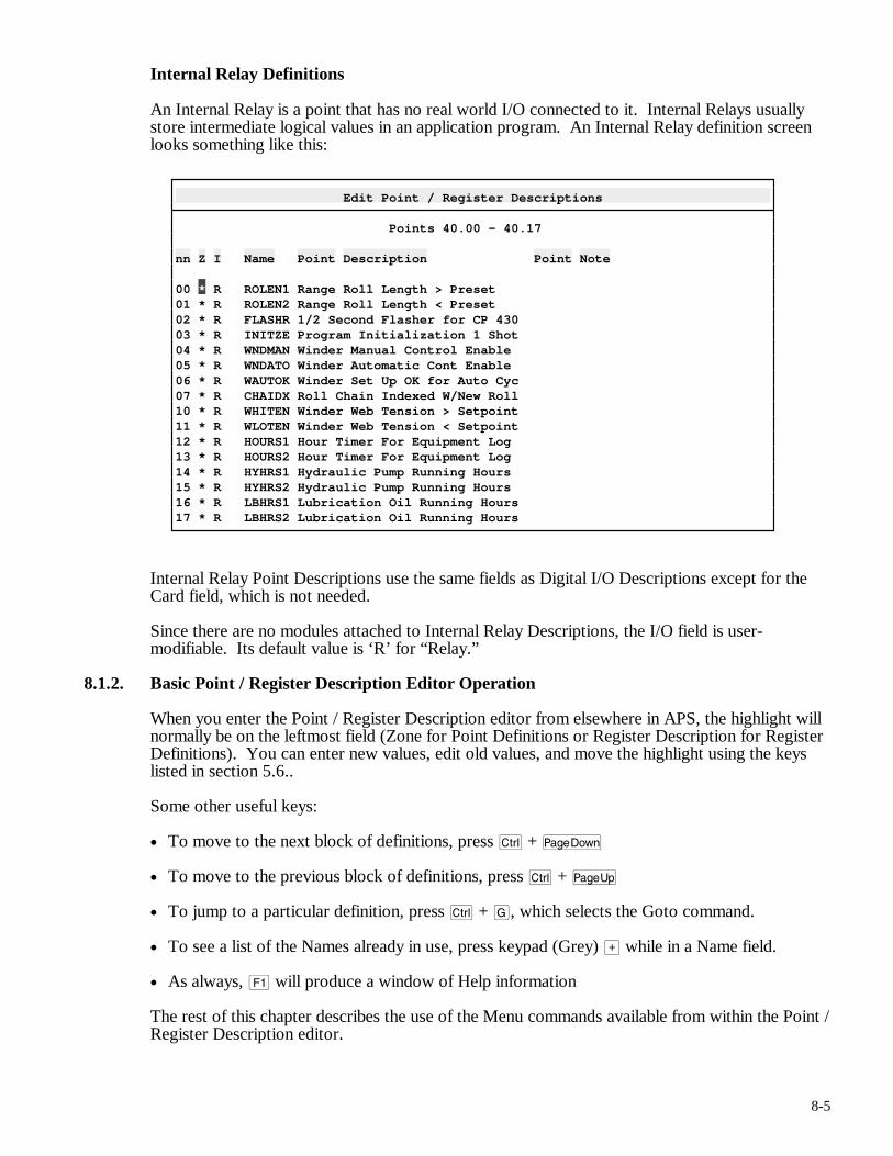
8-5
Internal Relay Definitions
An Internal Relay is a point that has no real world I/O connected to it. Internal Relays usually store intermediate logical values in an application program. An Internal Relay definition screen looks something like this:
Edit Point / Register Descriptions
Points 40.00 - 40.17 nn Z I Name Point Description Point Note 00 * R ROLEN1 Range Roll Length > Preset 01 * R ROLEN2 Range Roll Length < Preset 02 * R FLASHR 1/2 Second Flasher for CP 430 03 * R INITZE Program Initialization 1 Shot 04 * R WNDMAN Winder Manual Control Enable 05 * R WNDATO Winder Automatic Cont Enable 06 * R WAUTOK Winder Set Up OK for Auto Cyc 07 * R CHAIDX Roll Chain Indexed W/New Roll 10 * R WHITEN Winder Web Tension > Setpoint 11 * R WLOTEN Winder Web Tension < Setpoint 12 * R HOURS1 Hour Timer For Equipment Log 13 * R HOURS2 Hour Timer For Equipment Log 14 * R HYHRS1 Hydraulic Pump Running Hours 15 * R HYHRS2 Hydraulic Pump Running Hours 16 * R LBHRS1 Lubrication Oil Running Hours 17 * R LBHRS2 Lubrication Oil Running Hours
Internal Relay Point Descriptions use the same fields as Digital I/O Descriptions except for the Card field, which is not needed.
Since there are no modules attached to Internal Relay Descriptions, the I/O field is user-modifiable. Its default value is ‘R’ for “Relay.”
8.1.2. Basic Point / Register Description Editor Operation
When you enter the Point / Register Description editor from elsewhere in APS, the highlight will normally be on the leftmost field (Zone for Point Definitions or Register Description for Register Definitions). You can enter new values, edit old values, and move the highlight using the keys listed in section 5.6..
Some other useful keys:
• To move to the next block of definitions, press c + v
• To move to the previous block of definitions, press c + u
• To jump to a particular definition, press c + G, which selects the Goto command.
• To see a list of the Names already in use, press keypad (Grey) > while in a Name field.
• As always, ! will produce a window of Help information
The rest of this chapter describes the use of the Menu commands available from within the Point / Register Description editor.
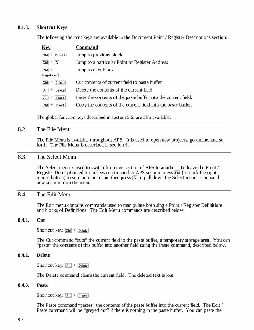
8-6
8.1.3. Shortcut Keys
The following shortcut keys are available in the Document Point / Register Descriptions section:
Key Command
c + u Jump to previous block
c + G Jump to a particular Point or Register Address
c + v
Jump to next block
c + d Cut contents of current field to paste buffer
a + d Delete the contents of the current field
a + i Paste the contents of the paste buffer into the current field.
c + i Copy the contents of the current field into the paste buffer.
The global function keys described in section 5.5. are also available.
8.2. The File Menu
The File Menu is available throughout APS. It is used to open new projects, go online, and so forth. The File Menu is described in section 6.
8.3. The Select Menu
The Select menu is used to switch from one section of APS to another. To leave the Point / Register Description editor and switch to another APS section, press ) (or click the right mouse button) to summon the menu, then press S to pull down the Select menu. Choose the new section from the menu.
8.4. The Edit Menu
The Edit menu contains commands used to manipulate both single Point / Register Definitions and blocks of Definitions. The Edit Menu commands are described below:
8.4.1. Cut
Shortcut key: c + d
The Cut command “cuts” the current field to the paste buffer, a temporary storage area. You can “paste” the contents of this buffer into another field using the Paste command, described below.
8.4.2. Delete
Shortcut key: a + d
The Delete command clears the current field. The deleted text is lost.
8.4.3. Paste
Shortcut key: a + i
The Paste command “pastes” the contents of the paste buffer into the current field. The Edit / Paste command will be “greyed out” if there is nothing in the paste buffer. You can paste the
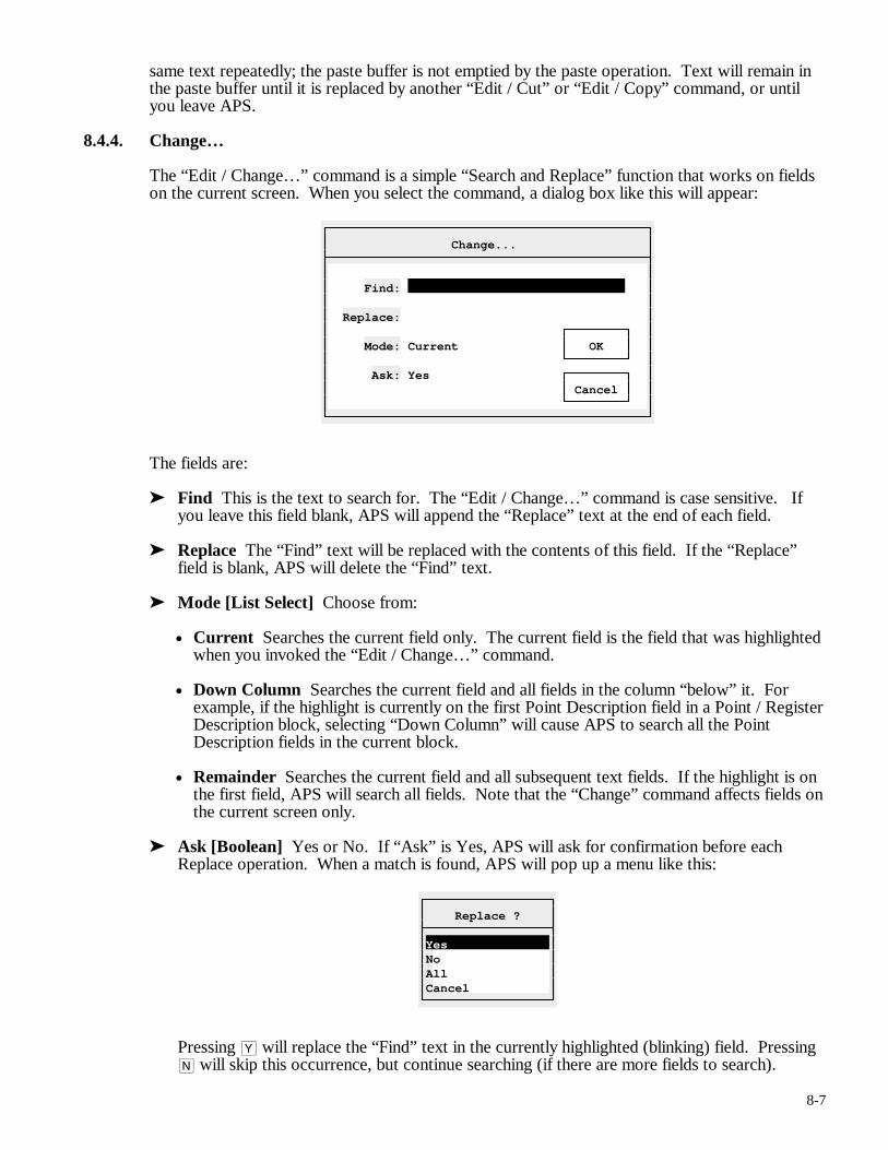
8-7
same text repeatedly; the paste buffer is not emptied by the paste operation. Text will remain in the paste buffer until it is replaced by another “Edit / Cut” or “Edit / Copy” command, or until you leave APS.
8.4.4. Change…
The “Edit / Change…” command is a simple “Search and Replace” function that works on fields on the current screen. When you select the command, a dialog box like this will appear:
Change...
Find: Replace: Mode: Current OK Ask: Yes Cancel
The fields are:
➤ Find This is the text to search for. The “Edit / Change…” command is case sensitive. If you leave this field blank, APS will append the “Replace” text at the end of each field.
➤ Replace The “Find” text will be replaced with the contents of this field. If the “Replace” field is blank, APS will delete the “Find” text.
➤ Mode [List Select] Choose from:
• Current Searches the current field only. The current field is the field that was highlighted when you invoked the “Edit / Change…” command.
• Down Column Searches the current field and all fields in the column “below” it. For example, if the highlight is currently on the first Point Description field in a Point / Register Description block, selecting “Down Column” will cause APS to search all the Point Description fields in the current block.
• Remainder Searches the current field and all subsequent text fields. If the highlight is on the first field, APS will search all fields. Note that the “Change” command affects fields on the current screen only.
➤ Ask [Boolean] Yes or No. If “Ask” is Yes, APS will ask for confirmation before each Replace operation. When a match is found, APS will pop up a menu like this:
Replace ?
Yes No All Cancel
Pressing Y will replace the “Find” text in the currently highlighted (blinking) field. Pressing N will skip this occurrence, but continue searching (if there are more fields to search).
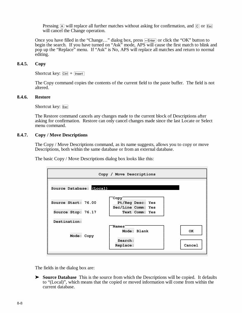
8-8
Pressing A will replace all further matches without asking for confirmation, and C or q will cancel the Change operation.
Once you have filled in the “Change…” dialog box, press r or click the “OK” button to begin the search. If you have turned on “Ask” mode, APS will cause the first match to blink and pop up the “Replace” menu. If “Ask” is No, APS will replace all matches and return to normal editing.
8.4.5. Copy
Shortcut key: c + i
The Copy command copies the contents of the current field to the paste buffer. The field is not altered.
8.4.6. Restore
Shortcut key: q
The Restore command cancels any changes made to the current block of Descriptions after asking for confirmation. Restore can only cancel changes made since the last Locate or Select menu command.
8.4.7. Copy / Move Descriptions
The Copy / Move Descriptions command, as its name suggests, allows you to copy or move Descriptions, both within the same database or from an external database.
The basic Copy / Move Descriptions dialog box looks like this:
Copy / Move Descriptions
Source Database: (Local) Copy Source Start: 76.00 Pt/Reg Desc: Yes Sec/Line Comm: Yes Source Stop: 76.17 Text Comm: Yes Destination: Names Mode: Blank OK Mode: Copy Search: Replace: Cancel
The fields in the dialog box are:
➤ Source Database This is the source from which the Descriptions will be copied. It defaults to “(Local)”, which means that the copied or moved information will come from within the current database.
8-9
To select a different project’s database, either type a project name (with path, if any) in the field or press keypad (Grey) > to select a project with an Open File dialog box. Section 6.2. describes the use of Open File boxes in more detail.
Note: If an external source project is currently open and you wish to return to copying within the current project, press d r while the highlight is on the “Source Database” field. This will leave the “Source Database” field blank. APS will interpret this as “Return to Local Copying.”
➤ Source Start This field determines the address of the first Description that will be copied or moved. This is a point or register address and can be either a numeric address (e.g., “0.17”) or a Name. If you are copying from an external database, this address is in the numbering scheme of the source database, not the current (target) database.
➤ Source Stop This is the address of the last Description that will be copied or moved. This is a point or register address and can be either a numeric address or a Name. If you are copying from an external database, this address is in the numbering scheme of the source database, not the current (target) database.
➤ Destination The address to which the information will be copied or moved. This must be a numeric point or register address. You can only copy points to points or registers to registers.
➤ Pt/Reg Desc [Boolean] Yes or No. Determines if Point / Register Descriptions will be copied or moved.
➤ Sec/Line Comm [Boolean] Yes or No. Determines if Section / Line Comments will be copied or moved. Using this option will copy or move attached Section and Line Comments within the Source range. This option is ignored if you are copying Register Descriptions.
➤ Text Comm [Boolean] Yes or No. Determines if Text Comments will be copied or moved. Using this option will copy or move attached Text Comments within the Source range. This option is ignored if you are copying Register Descriptions.
➤ Mode [Boolean] Copy or Move. Copy mode duplicates Descriptions; Move mode copies and deletes Descriptions. Note that deleted Point / Register Descriptions are actually blanked, not deleted. This is because there may be other descriptions left in the source blocks after the move. Point / Register Descriptions can only be deleted in blocks of 16.
To delete empty Point / Register Description blocks after a Move, you can use the Purge Descriptions command (see below).
➤ Search This field is only used when you are copying Point Descriptions. Since Names must be unique within each database, you cannot simply copy a block of Point Descriptions (unless all the Names are blank). Every Name would be a duplicate.
The Search and Replace fields are designed to deal with this problem. When you copy Point Descriptions with the Search and Replace fields filled in, APS will scan each Name for the Search string and replace it (if found) with the Replace string. The Replace string can be empty, in which case APS will delete the Search string. After each search and replace, APS will truncate the new Name to six characters.
This field is ignored if you are not copying Point Descriptions.
➤ Replace Used with Search (see above).
After you have filled in the necessary fields, press r to initiate the copy or move. Press q to cancel.
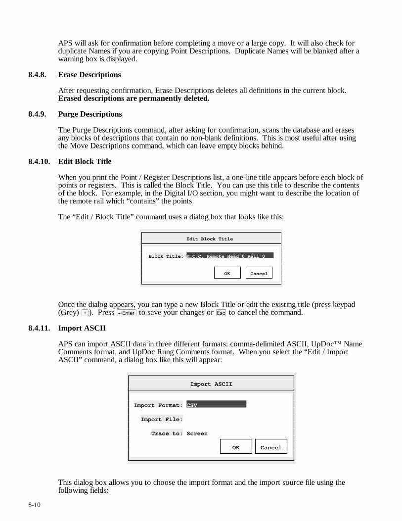
8-10
APS will ask for confirmation before completing a move or a large copy. It will also check for duplicate Names if you are copying Point Descriptions. Duplicate Names will be blanked after a warning box is displayed.
8.4.8. Erase Descriptions
After requesting confirmation, Erase Descriptions deletes all definitions in the current block. Erased descriptions are permanently deleted.
8.4.9. Purge Descriptions
The Purge Descriptions command, after asking for confirmation, scans the database and erases any blocks of descriptions that contain no non-blank definitions. This is most useful after using the Move Descriptions command, which can leave empty blocks behind.
8.4.10. Edit Block Title
When you print the Point / Register Descriptions list, a one-line title appears before each block of points or registers. This is called the Block Title. You can use this title to describe the contents of the block. For example, in the Digital I/O section, you might want to describe the location of the remote rail which “contains” the points.
The “Edit / Block Title” command uses a dialog box that looks like this:
Edit Block Title
Block Title: M.C.C. Remote Head 0 Rail 0 OK Cancel
Once the dialog appears, you can type a new Block Title or edit the existing title (press keypad (Grey) >). Press r to save your changes or q to cancel the command.
8.4.11. Import ASCII
APS can import ASCII data in three different formats: comma-delimited ASCII, UpDoc™ Name Comments format, and UpDoc Rung Comments format. When you select the “Edit / Import ASCII” command, a dialog box like this will appear:
Import ASCII
Import Format: CSV Import File: Trace to: Screen OK Cancel
This dialog box allows you to choose the import format and the import source file using the following fields:
8-11
➤ Import Format [List Select] Choose from CSV (Comma-Separated), UpDoc Names, and UpDoc Rungs. The comma-delimited format is described below in the “Edit / Export ASCII” command section.
UpDoc Names Format
In the UpDoc Names format, each Name record begins with a valid register or point address followed by any number of whitespace characters (spaces or tabs), then three nine-character text definition columns terminated by a Carriage Return / Linefeed pair. Note that these text columns are position dependent; no specific separator character is used.
APS will create a definition for each register or point with the Name field generated by chaining together the three text definition fields. Excess blanks will automatically be removed. The Note, Name, and Card Code fields are left empty in new records created by the Import Names function.
Some sample UpDoc Names records:
Registers:
1750 GO SUB STATUS BIT MAP 2000 LOAD SHEDPRIORITY TABLE
Points:
01.05 FIELD OUTPUTS P/L 01.06 SIMULATORINPUTS P/L
UpDoc Rungs Format
In the UpDoc Rungs format, each comment must begin with a valid point address on a line by itself. It is very important that the point address begin in the first column of the line.
After the point address come the comment lines. Each comment line must begin with at least one whitespace character. The UpDoc standard permits up to 50 characters per comment line; APS will store up to 60 characters per line.
Some sample UpDoc Rungs records:
11.02 Single Line Comment
11.16 ************************************ Multi-line comment including borders. Such comments can be up to 1000 lines long. ************************************
➤ Import File Enter the complete path and filename of the import source file.
➤ Trace to [Boolean] Screen or Printer. The “Trace to” field determines what happens to the error report generated by the Import ASCII command. The default option, “Screen,” sends the report to the display in a scrollable window. Select “Printer” to send the error report to the current printer device.
The Trace report lists any invalid records discovered during the import operation. Records may be invalid due to duplicate Names, illegal addresses, etc.
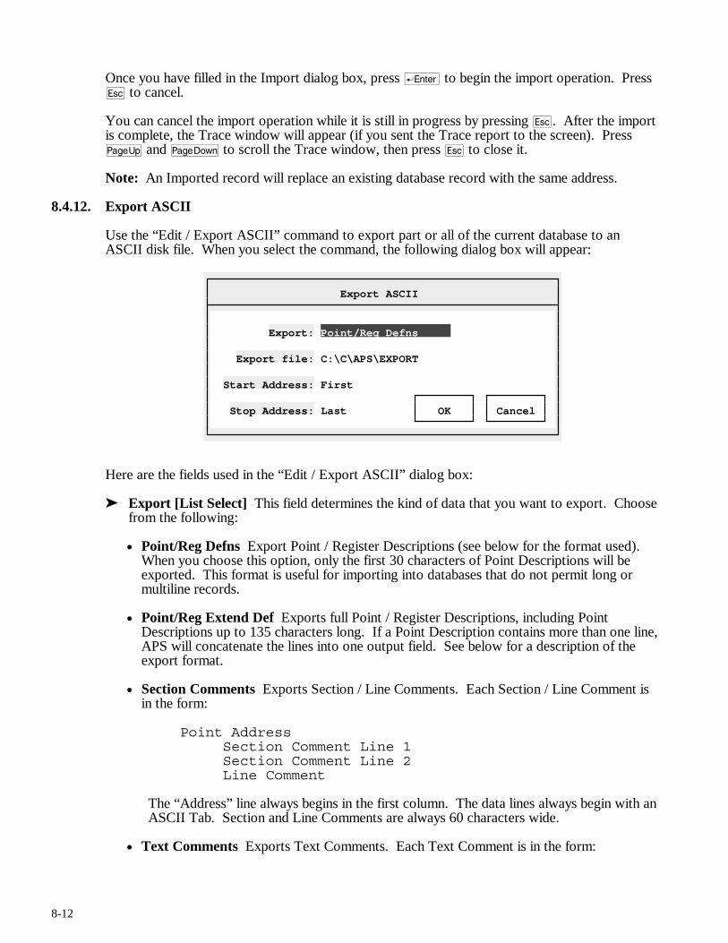
8-12
Once you have filled in the Import dialog box, press r to begin the import operation. Press q to cancel.
You can cancel the import operation while it is still in progress by pressing q. After the import is complete, the Trace window will appear (if you sent the Trace report to the screen). Press u and v to scroll the Trace window, then press q to close it.
Note: An Imported record will replace an existing database record with the same address.
8.4.12. Export ASCII
Use the “Edit / Export ASCII” command to export part or all of the current database to an ASCII disk file. When you select the command, the following dialog box will appear:
Export ASCII
Export: Point/Reg Defns Export file: C:\C\APS\EXPORT Start Address: First Stop Address: Last OK Cancel
Here are the fields used in the “Edit / Export ASCII” dialog box:
➤ Export [List Select] This field determines the kind of data that you want to export. Choose from the following:
• Point/Reg Defns Export Point / Register Descriptions (see below for the format used). When you choose this option, only the first 30 characters of Point Descriptions will be exported. This format is useful for importing into databases that do not permit long or multiline records.
• Point/Reg Extend Def Exports full Point / Register Descriptions, including Point Descriptions up to 135 characters long. If a Point Description contains more than one line, APS will concatenate the lines into one output field. See below for a description of the export format.
• Section Comments Exports Section / Line Comments. Each Section / Line Comment is in the form:
Point Address Section Comment Line 1 Section Comment Line 2 Line Comment
The “Address” line always begins in the first column. The data lines always begin with an ASCII Tab. Section and Line Comments are always 60 characters wide.
• Text Comments Exports Text Comments. Each Text Comment is in the form:
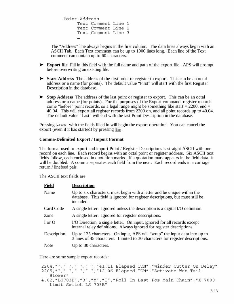
8-13
Point Address Text Comment Line 1 Text Comment Line 2 Text Comment Line 3 …
The “Address” line always begins in the first column. The data lines always begin with an ASCII Tab. Each Text comment can be up to 1000 lines long. Each line of the Text comment can contain up to 60 characters.
➤ Export file Fill in this field with the full name and path of the export file. APS will prompt before overwriting an existing file.
➤ Start Address The address of the first point or register to export. This can be an octal address or a name (for points). The default value “First” will start with the first Register Description in the database.
➤ Stop Address The address of the last point or register to export. This can be an octal address or a name (for points). For the purposes of the Export command, register records come “before” point records, so a legal range might be something like start = 2200, end = 40.04. This will export all register records from 2200 on, and all point records up to 40.04. The default value “Last” will end with the last Point Description in the database.
Pressing r with the fields filled in will begin the export operation. You can cancel the export (even if it has started) by pressing q.
Comma-Delimited Export / Import Format
The format used to export and import Point / Register Descriptions is straight ASCII with one record on each line. Each record begins with an octal point or register address. Six ASCII text fields follow, each enclosed in quotation marks. If a quotation mark appears in the field data, it will be doubled. A comma separates each field from the next. Each record ends in a carriage return / linefeed pair.
The ASCII text fields are:
Field Description
Name Up to six characters, must begin with a letter and be unique within the database. This field is ignored for register descriptions, but must still be included.
Card Code A single letter. Ignored unless the description is a digital I/O definition.
Zone A single letter. Ignored for register descriptions.
I or O I/O Direction, a single letter. On input, ignored for all records except internal relay definitions. Always ignored for register descriptions.
Description Up to 135 characters. On input, APS will “wrap” the input data into up to 3 lines of 45 characters. Limited to 30 characters for register descriptions.
Note Up to 30 characters.
Here are some sample export records:
2204,”“,” “,” “,” “,”41.11 Elapsed TON”,”Winder Cutter On Delay” 2205,”“,” “,” “,” “,”12.06 Elapsed TON”,”Activate Web Tail
Blower” 4.02,”LS703B”,”3”,”M”,”I”,”Roll In Last Pos Main Chain”,”X 7000
Limit Switch LS 703B”
8-14
4.03,”LS704A”,” “,”M”,”I”,”New Roll In Main Chain Saddle”,”X 7000 Limit Switch LS 704A”
8.5. The Locate Menu
The Locate menu changes your location in the list of Point / Register Descriptions. It is used both to scroll through the list and to add new blocks of definitions to the list.
8.5.1. First
Use the “Locate / First” command to jump to the first point (or register, if you are currently defining registers) block in the database.
8.5.2. Previous
Shortcut key: c + u
Use the “Locate / Previous” command to jump to the previous point (or register, if you are currently defining registers) block in the database.
8.5.3. Next
Shortcut key: c + v
Use the “Locate / Previous” command to jump to the next point (or register, if you are currently defining registers) block in the database.
8.5.4. Last
Use the “Locate / Previous” command to jump to the last point (or register, if you are currently defining registers) block in the database.
8.5.5. Goto
Shortcut key: c + G
Use the “Locate / Previous” command to jump to a particular point or register description. To jump to a point, enter an octal point address or an existing name. To jump to a register, enter an octal register address.
If you try to jump to a description that does not yet exist, APS will offer you an opportunity to create a new block. If you have entered a Point address in the current Processor’s digital I/O range, APS will also ask “Is the point used as digital I/O?” Press Y if this block is configured for use as real I/O or N to use the block as internal relays.
8.6. The Print Menu
From the Document Point / Register Descriptions “Print” menu, you can generate most of APS’s key reports, including the Documented Ladder Listing. The commands available from the Print menu are:
8.6.1. Ladder / Xref…
The “Print / Ladder / Xref…” command prints APS’s most important report, the Documented Ladder Listing. These listings are generated in five “phases” or sections: header page, ladder sequences, output index, section (title) index, contact crossreference, and register crossreference.
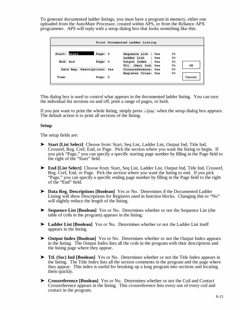
8-15
To generate documented ladder listings, you must have a program in memory, either one uploaded from the AutoMate Processor, created within APS, or from the Reliance APX programmer. APS will reply with a setup dialog box that looks something like this:
Print Documented Ladder Listing
Start: Start Page: 0 Sequence List : Yes 0% Ladder List : Yes 0% End: End Page: 0 Output Index : Yes 0% Ttl. (Sec) Ind: Yes 0% OK Data Reg. Descriptions: Yes Crossreference: Yes 0% Register Cross: Yes 0% Time: Page: 0 Cancel
This dialog box is used to control what appears in the documented ladder listing. You can turn the individual list sections on and off, print a range of pages, or both.
If you just want to print the whole listing, simply press r when the setup dialog box appears. The default action is to print all sections of the listing.
Setup
The setup fields are:
➤ Start [List Select] Choose from: Start, Seq List, Ladder List, Output Ind, Title Ind, Crossref, Reg. Cref, End, or Page. Pick the section where you want the listing to begin. If you pick “Page,” you can specify a specific starting page number by filling in the Page field to the right of the “Start” field.
➤ End [List Select] Choose from: Start, Seq List, Ladder List, Output Ind, Title Ind, Crossref, Reg. Cref, End, or Page. Pick the section where you want the listing to end. If you pick “Page,” you can specify a specific ending page number by filling in the Page field to the right of the “End” field.
➤ Data Reg. Descriptions [Boolean] Yes or No. Determines if the Documented Ladder Listing will show Descriptions for Registers used in function blocks. Changing this to “No” will slightly reduce the length of the listing.
➤ Sequence List [Boolean] Yes or No. Determines whether or not the Sequence List (the table of coils in the program) appears in the listing.
➤ Ladder List [Boolean] Yes or No. Determines whether or not the Ladder List itself appears in the listing.
➤ Output Index [Boolean] Yes or No. Determines whether or not the Output Index appears in the listing. The Output Index lists all the coils in the program with their descriptions and the listing page where they appear.
➤ Ttl. (Sec) Ind [Boolean] Yes or No. Determines whether or not the Title Index appears in the listing. The Title Index lists all the section comments in the program and the page where they appear. This index is useful for breaking up a long program into sections and locating them quickly.
➤ Crossreference [Boolean] Yes or No. Determines whether or not the Coil and Contact Crossreference appears in the listing. This crossreference lists every use of every coil and contact in the program.
8-16
➤ Register Cross [Boolean] Yes or No. Determines whether or not the Register Crossreference appears in the listing. This crossreference lists every use of every register in the program.
The Documented Listing
Throughout the ladder listing, APS uses two important symbol conventions. Any number that begins with a ‘>‘ symbol is a line number, and any number preceded by a ‘:’ is a page number.
For example, the text “] [ 43.05>221:55” in the Contact Crossreference means that the contact in question has been used as a Normally Open Contact in rung 43.05, line number 221, on listing page 55.
Below is a description of the different sections of the Documented Listing in the order that they are printed:
• Sequence List The documentation begins with a header page that lists all the sequences in the application program in order of occurrence. It also lists the total size of the program and the line number where each sequence is defined.
For example, the text “10.03>280” on the header page indicates that Coil 10.03 is found at line 280.
• Ladder Listing Next comes the ladder listing. For every rung in the program, each contact in the input logic is shown with its name (if any), and each occupied rung of the sequence is numbered. The Line Number appears at the extreme left, and is followed by a ‘>‘ symbol.
The Coil Crossreference (places where the rung’s coil is used as a contact) appears to the right of the rung below the name of the rung’s primary output or coil.
In the Coil Crossreference, you might see something like:
] [: 10.03>237, 2000.12>55 ]/[: 21.15>112 ]^[: 47.03>20
This means that the current rung’s coil was used as a Normally Open contact in rung 10.03 (on line 237) and in rung 2000.12 on line 55. The coil has also been used as a Normally Closed contact in rung 21.15 (on line 112), and as a Transitional contact in rung 47.03 (line 20).
For function blocks with two non-error outputs (like CMP), APS will also crossreference the second coil. The second coil’s crossreference will appear immediately below the first coil crossreference. Both crossreferences use exactly the same notation. The second crossreference is separated from the first by a horizontal line.
Definitions for all the contacts used in the rung (and register definitions if you enabled them) appear to the right of the rung itself below the coil crossreference. Contact definitions are sorted by point address.
Each Contact point number is followed by a code such as (IR) which describes the point type. The valid codes are:
Code Contact Type
(Dx) Digital Point (x is I or O depending on card)
(Ix) Internal Point (x depends on I column)*
(Gx) Global Point (x depends on I column)*
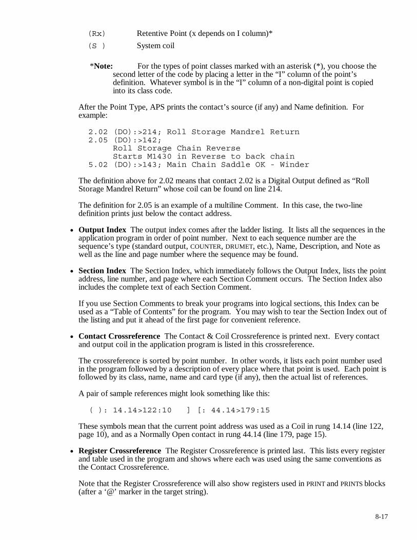
8-17
(Rx) Retentive Point (x depends on I column)*
(S ) System coil
*Note: For the types of point classes marked with an asterisk (*), you choose the second letter of the code by placing a letter in the “I” column of the point’s definition. Whatever symbol is in the “I” column of a non-digital point is copied into its class code.
After the Point Type, APS prints the contact’s source (if any) and Name definition. For example:
2.02 (DO):>214; Roll Storage Mandrel Return 2.05 (DO):>142; Roll Storage Chain Reverse Starts M1430 in Reverse to back chain 5.02 (DO):>143; Main Chain Saddle OK - Winder
The definition above for 2.02 means that contact 2.02 is a Digital Output defined as “Roll Storage Mandrel Return” whose coil can be found on line 214.
The definition for 2.05 is an example of a multiline Comment. In this case, the two-line definition prints just below the contact address.
• Output Index The output index comes after the ladder listing. It lists all the sequences in the application program in order of point number. Next to each sequence number are the sequence’s type (standard output, COUNTER, DRUMET, etc.), Name, Description, and Note as well as the line and page number where the sequence may be found.
• Section Index The Section Index, which immediately follows the Output Index, lists the point address, line number, and page where each Section Comment occurs. The Section Index also includes the complete text of each Section Comment.
If you use Section Comments to break your programs into logical sections, this Index can be used as a “Table of Contents” for the program. You may wish to tear the Section Index out of the listing and put it ahead of the first page for convenient reference.
• Contact Crossreference The Contact & Coil Crossreference is printed next. Every contact and output coil in the application program is listed in this crossreference.
The crossreference is sorted by point number. In other words, it lists each point number used in the program followed by a description of every place where that point is used. Each point is followed by its class, name, name and card type (if any), then the actual list of references.
A pair of sample references might look something like this:
( ): 14.14>122:10 ] [: 44.14>179:15
These symbols mean that the current point address was used as a Coil in rung 14.14 (line 122, page 10), and as a Normally Open contact in rung 44.14 (line 179, page 15).
• Register Crossreference The Register Crossreference is printed last. This lists every register and table used in the program and shows where each was used using the same conventions as the Contact Crossreference.
Note that the Register Crossreference will also show registers used in PRINT and PRINTS blocks (after a ‘@’ marker in the target string).

8-18
8.6.2. Name Index
After asking for confirmation, the Name Index command prints every point in the database that has a name, sorting the records by name.
8.6.3. Point / Register List
The Point / Register List report shows the current contents of the Point / Register Descriptions list sorted by address.
When you select this command, APS will display a dialog box like this:
Print Point / Reg Desc.
Range to Print: OK Start: 0 Stop: 3777.17 Cancel
Select the range of Point / Register Descriptions that you want to print. Pressing r will start the listing. q will cancel the dialog (or this listing once it has started).
For the purposes of this report, Register Descriptions come “before” Point Descriptions. For example, the print range “Start at 10, End at 2000.17” is legal: it would print all registers 10 or above and all points less than or equal to 2000.17. The reverse “Start at 2000.17, End at 10” is not.
8.6.4. Hardware List
The Hardware List asks for confirmation, then prints a list of all the hardware (I/O modules, racks, rack cards, rails, Local Heads, and Remote Heads) used in the program. This report will only be accurate if you have entered the relevant data into the database by attaching I/O modules to points, setting up Rack Descriptions, and so forth.
8.6.5. Card List
The Card List command prints the current list of I/O module and rack card definitions. See section 8.9. for more information about the Card Lists.
8.6.6. Align Tags
APS can print wire tags to simplify field wiring. It prints these tags on label stock manufactured by the W. H. Brady Co., part number Z8960 / DAT-7-292-10.
Use the Align Tags command to set up for wire tag printing. Load the labels into the printer and select “Print / Align Tags.” APS will send a test pattern to the printer each time that you execute this command.
The test pattern should be exactly centered on the white portion of the label. Exact registration is important. If the labels are not aligned properly, parts of the information to be printed on the labels may end up on the backing paper and make the labels useless. There is very little margin for error; the label printing routine uses nearly the whole label. See the “Print / Wire Tags…” command below for details.
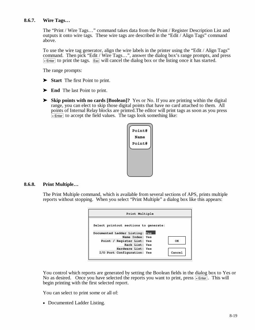
8-19
8.6.7. Wire Tags…
The “Print / Wire Tags…” command takes data from the Point / Register Description List and outputs it onto wire tags. These wire tags are described in the “Edit / Align Tags” command above.
To use the wire tag generator, align the wire labels in the printer using the “Edit / Align Tags” command. Then pick “Edit / Wire Tags…”, answer the dialog box’s range prompts, and press r to print the tags. q will cancel the dialog box or the listing once it has started.
The range prompts:
➤ Start The first Point to print.
➤ End The last Point to print.
➤ Skip points with no cards [Boolean]? Yes or No. If you are printing within the digital range, you can elect to skip those digital points that have no card attached to them. All points of Internal Relay blocks are printed.The editor will print tags as soon as you press r to accept the field values. The tags look something like:
Point#
Name
Point#
8.6.8. Print Multiple…
The Print Multiple command, which is available from several sections of APS, prints multiple reports without stopping. When you select “Print Multiple” a dialog box like this appears:
Print Multiple
Select printout sections to generate: Documented Ladder Listing: Yes Name Index: Yes Point / Register List: Yes OK Rack List: Yes Hardware List: Yes I/O Port Configuration: Yes Cancel
You control which reports are generated by setting the Boolean fields in the dialog box to Yes or No as desired. Once you have selected the reports you want to print, press r. This will begin printing with the first selected report.
You can select to print some or all of:
• Documented Ladder Listing.
8-20
• Name Index.
• Point / Register List.
• Rack List.
• Hardware List.
• I/O Port Configuration.
You can cancel the reports at any time by pressing q, though you may have to press it more than once before APS obeys.
Note: If you are printing to a relatively slow device, such as a dot-matrix printer, a full complement of listings can take several hours to print. This is one of the main uses of Print Multiple; you can, for example, leave several reports to print overnight. If you are going to be doing a large amount of documented printing with APS, we strongly recommend the use of a laser printer.
8.6.9. Top of Form
The Top of Form command sends a “Top-of-Form” character (ASCII 12) to the current printer device.
8.7. The Utility Menu
The Utility Menu is available throughout APS. It is used to configure printers, set communications parameters, and so forth. The Utility Menu is described in section 7.
8.8. The AutoGen Menu
The AutoGen Menu contains commands that generate definitions automatically by combining information in your application program and project database.
8.8.1. Add Point Descriptions
The Add Point Descriptions feature reads the configuration table from the application program and makes sure that there is a digital type point block defined for each register used in the configuration.
For example, if your application program I/O configuration uses registers 0 - 3, 12, and 17, the “Add Point Descriptions” command will make sure that digital point blocks 0.00 - 0.17, 1.00 - 1.17, 2.00 - 2.17, 3.00 - 3.17, 12.00 - 12.17, and 17.00 - 17.17 are all defined. If any of those point blocks do not exist, they will be created.
8.8.2. Create Register Descriptions
The “AutoGen / Create Register Descriptions” command scans through the application looking for function blocks such as Timers, Counters, and so forth. Each time that it encounters a function block, it determines which registers the block uses.
If any of those registers are undefined or have blank definitions, the “AutoGen / Create Register Descriptions” command will generate and add a definition from the I/O List and function block data. When the editor generates these definitions, it puts the following information into the Name field:
• Point Number. The sequence number of the function block’s primary output.
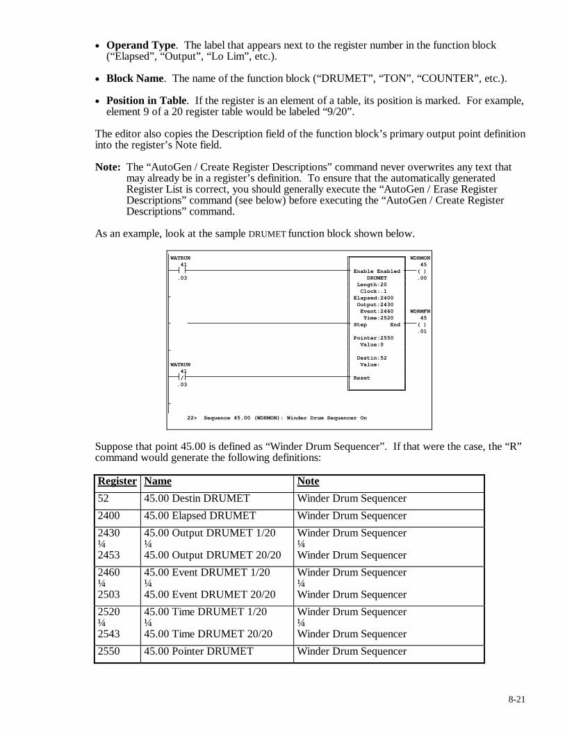
8-21
• Operand Type. The label that appears next to the register number in the function block (“Elapsed”, “Output”, “Lo Lim”, etc.).
• Block Name. The name of the function block (“DRUMET”, “TON”, “COUNTER”, etc.).
• Position in Table. If the register is an element of a table, its position is marked. For example, element 9 of a 20 register table would be labeled “9/20”.
The editor also copies the Description field of the function block’s primary output point definition into the register’s Note field.
Note: The “AutoGen / Create Register Descriptions” command never overwrites any text that may already be in a register’s definition. To ensure that the automatically generated Register List is correct, you should generally execute the “AutoGen / Erase Register Descriptions” command (see below) before executing the “AutoGen / Create Register Descriptions” command.
As an example, look at the sample DRUMET function block shown below.
WATRUN WDRMON 41 45
Enable Enabled ( ) .03 DRUMET .00 Length:20 Clock:.1 Elapsed:2400 Output:2430 Event:2460 WDRMFN Time:2520 45 Step End ( ) .01 Pointer:2550 Value:0 Destin:52 WATRUN Value: 41
/ Reset .03 22> Sequence 45.00 (WDRMON): Winder Drum Sequencer On
Suppose that point 45.00 is defined as “Winder Drum Sequencer”. If that were the case, the “R” command would generate the following definitions:
Register Name Note
52 45.00 Destin DRUMET Winder Drum Sequencer
2400 45.00 Elapsed DRUMET Winder Drum Sequencer
2430 ¼ 2453
45.00 Output DRUMET 1/20 ¼ 45.00 Output DRUMET 20/20
Winder Drum Sequencer ¼ Winder Drum Sequencer
2460 ¼ 2503
45.00 Event DRUMET 1/20 ¼ 45.00 Event DRUMET 20/20
Winder Drum Sequencer ¼ Winder Drum Sequencer
2520 ¼ 2543
45.00 Time DRUMET 1/20 ¼ 45.00 Time DRUMET 20/20
Winder Drum Sequencer ¼ Winder Drum Sequencer
2550 45.00 Pointer DRUMET Winder Drum Sequencer
8-22
8.8.3. Erase Register Descriptions
The Erase Register Descriptions command is used with the “AutoGen / Create Register Descriptions” command to ensure that the list of register definitions is up to date. Since the editor is capable of generating a definition for each register used in the application program (see the “AutoGen / Create Register Descriptions” command above), the register list can essentially be maintained automatically.
However, the “AutoGen / Create Register Descriptions” command never erases existing nonblank register definitions; it only adds new ones. This means that the machine-generated register list may become outdated as the application program is modified: old definitions left behind by previous runs of the “AutoGen / Create Register Descriptions” command will remain in the list, and new or modified definitions will not write over existing definitions.
The “AutoGen / Erase Register Descriptions” command takes care of this problem. It scans through the entire list of register definitions and blanks any definition that does not begin with a ‘*’. In other words, you may protect a register definition that you have added yourself by beginning it with an asterisk. Since the “AutoGen / Create Register Descriptions” command does not begin its definitions with a ‘*’, all the machine generated texts will be erased. Any definitions that you add (and precede with an asterisk) will not be erased. If you execute the “AutoGen / Create Register Descriptions” command after the “AutoGen / Erase Register Descriptions” command, the register list definitions will all be current.
8.9. The Card Lists
APS maintains two Card Lists. Each card list contains a set of code letters (‘0’ to ‘9’, ‘A’ to ‘Z’, and ‘a’ to ‘h’) and the card names and part numbers that the codes correspond to. One list (the “Digital” card list) is used in the Point / Register Descriptions editor, and the other is used in the Rack Definition editor (the “Rack” card list).
When you create a new project, APS supplies default definitions for both card lists. You can, however, redefine any or all the card definitions to suit your needs.
Editing Card Definitions
To edit a card list, you must be in the corresponding section of APS: to edit the Digital Card List, you must be in the Point / Register Descriptions editor; to edit the Rack Card List, you must be in the Rack Definitions editor. Once you are in the correct section, move the cursor onto a Card field and press keypad (Grey) >. This will bring up a list window showing the current card definitions. You may have already used this window to choose cards in your database.
To edit a card definition, move the highlight onto the desired card code and press keypad (Grey) >. Note that you are pressing keypad (Grey) > for a second time, once to pull up the card list window and once to edit the card definition.
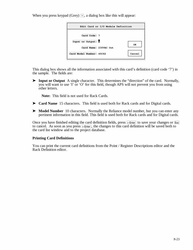
8-23
When you press keypad (Grey) >, a dialog box like this will appear:
Edit Card or I/O Module Definition
Card Code: 7 Input or Output: O OK Card Name: 230VAC Out Card Model Number: 45C62 Cancel
This dialog box shows all the information associated with this card’s definition (card code ‘7’) in the sample. The fields are:
➤ Input or Output A single character. This determines the “direction” of the card. Normally, you will want to use ‘I’ or ‘O’ for this field, though APS will not prevent you from using other letters.
Note: This field is not used for Rack Cards.
➤ Card Name 15 characters. This field is used both for Rack cards and for Digital cards.
➤ Model Number 10 characters. Normally the Reliance model number, but you can enter any pertinent information in this field. This field is used both for Rack cards and for Digital cards.
Once you have finished editing the card definition fields, press r to save your changes or q to cancel. As soon as you press r, the changes to this card definition will be saved both to the card list window and to the project database.
Printing Card Definitions
You can print the current card definitions from the Point / Register Descriptions editor and the Rack Definition editor.

9-1
9. Document Sequence Descriptions Shortcut key: &
You can use Sequence Descriptions to add information about individual sequences. These descriptions appear above the rungs in the Documented Ladder Listing.
9.1. Introduction
Sequence Descriptions are comments that print above rungs in the Documented Ladder Listing. Sequence Descriptions are manipulated by their addresses, which are always the same as that of the coil they are attached to.
From the Document Sequence Descriptions section, you can:
• Attach Sequence Descriptions to rungs
• Edit, copy, move, and delete existing Descriptions
9.1.1. Description Types
There are three types of Sequence Descriptions:
• Section Comment A Section Comment is two lines of 60 characters that start a new page and print in a box.
• Text Comment Text Comments are blocks of lines (60 characters each) up to 1000 lines long. They print below the Section Comment (if any).
• Line Comment A Line Comment is a single line of 60 characters that prints in emphasized type just above the rung.
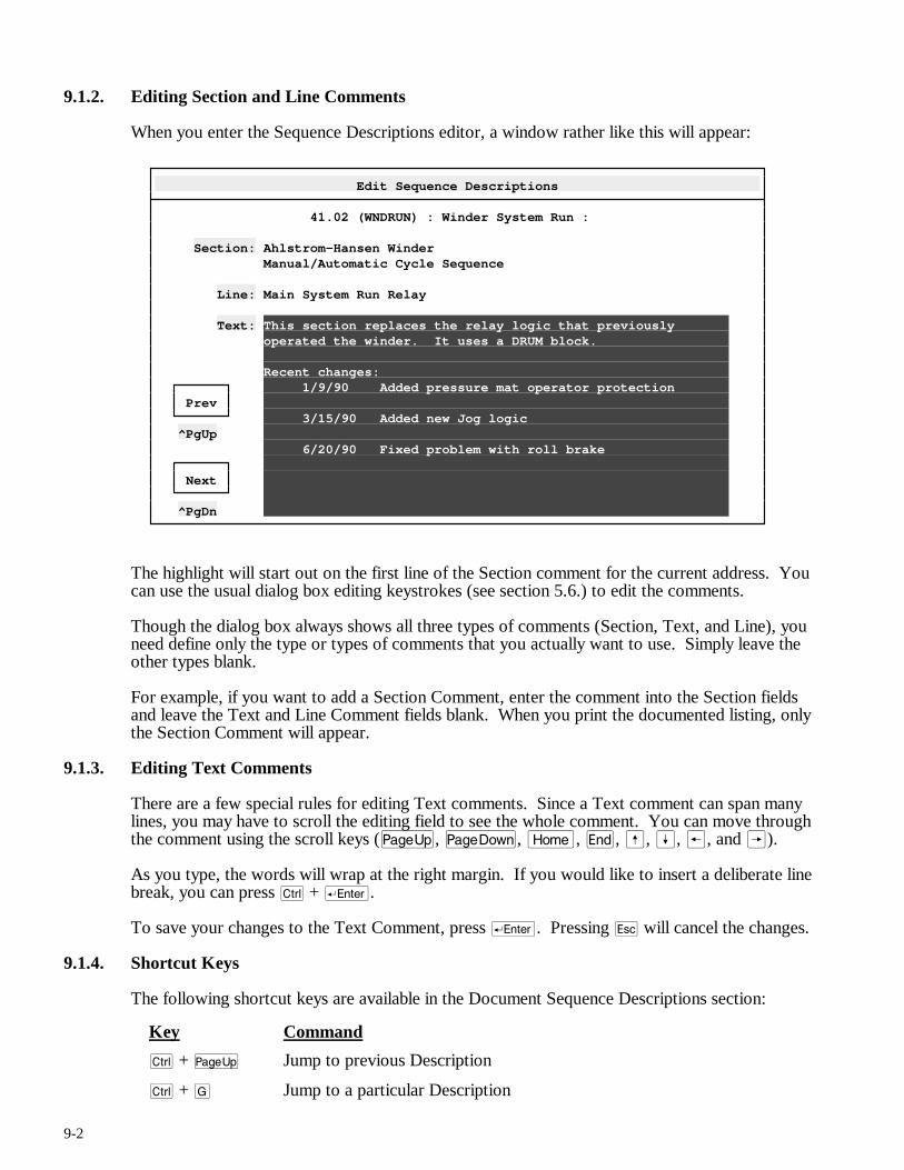
9-2
9.1.2. Editing Section and Line Comments
When you enter the Sequence Descriptions editor, a window rather like this will appear:
Edit Sequence Descriptions
41.02 (WNDRUN) : Winder System Run : Section: Ahlstrom-Hansen Winder Manual/Automatic Cycle Sequence Line: Main System Run Relay Text: This section replaces the relay logic that previously operated the winder. It uses a DRUM block. Recent changes: 1/9/90 Added pressure mat operator protection Prev 3/15/90 Added new Jog logic ^PgUp 6/20/90 Fixed problem with roll brake Next ^PgDn
The highlight will start out on the first line of the Section comment for the current address. You can use the usual dialog box editing keystrokes (see section 5.6.) to edit the comments.
Though the dialog box always shows all three types of comments (Section, Text, and Line), you need define only the type or types of comments that you actually want to use. Simply leave the other types blank.
For example, if you want to add a Section Comment, enter the comment into the Section fields and leave the Text and Line Comment fields blank. When you print the documented listing, only the Section Comment will appear.
9.1.3. Editing Text Comments
There are a few special rules for editing Text comments. Since a Text comment can span many lines, you may have to scroll the editing field to see the whole comment. You can move through the comment using the scroll keys (u, v, m, e, ß, Í, ®, and Â).
As you type, the words will wrap at the right margin. If you would like to insert a deliberate line break, you can press c + r.
To save your changes to the Text Comment, press r. Pressing q will cancel the changes.
9.1.4. Shortcut Keys
The following shortcut keys are available in the Document Sequence Descriptions section:
Key Command
c + u Jump to previous Description
c + G Jump to a particular Description
9-3
c + v Jump to next Description
c + d Cut contents of current field to paste buffer
a + d Delete the contents of the current field
a + i Paste the contents of the paste buffer into the current field.
c + i Copy the contents of the current field into the paste buffer.
The global function keys described in section 5.5. are also available.
9.2. The File Menu
The File Menu is available throughout APS. It is used to open new projects, go online, and so forth. The File Menu is described in section 6.
9.3. The Select Menu
Throughout APS, the Select menu is used to switch from one section of the program to another. To leave the Sequence Description editor and switch to another APS section, press ) (or click the right mouse button) to summon the menu, then press S to pull down the Select menu. Choose the new section from the menu.
9.4. The Edit Menu
The Edit menu contains commands used to manipulate both individual comments and Sequence Descriptions. The Edit menu commands are described below.
9.4.1. Cut
Shortcut key: c + d
The Cut command “cuts” the current field to the paste buffer, a temporary storage area. You can “paste” the contents of this buffer into another field using the Paste command, described below.
9.4.2. Delete
Shortcut key: a + d
The Delete command clears the current field. The deleted text is lost.
9.4.3. Paste
Shortcut key: a + i
The Paste command “pastes” the contents of the paste buffer into the current field. The Edit / Paste command will be “greyed out” if there is nothing in the paste buffer. You can paste the same text repeatedly; the paste buffer is not emptied by the Paste operation. Text will remain in the paste buffer until it is replaced by another “Edit / Cut” or “Edit / Copy” command, or until you leave APS.
9.4.4. Change…
The “Edit / Change…” command is designed to search and replace text. For a description of the “Change…” command, please see section 8.4.4.
9-4
9.4.5. Copy
Shortcut key: c + i
The Copy command copies the contents of the current field to the paste buffer. The field is not altered.
9.4.6. Restore
Shortcut key: q
The Restore command cancels any changes made to the current block of Descriptions after asking for confirmation. Restore can only cancel changes made since the last Locate or Select menu command.
9.4.7. Copy / Move Descriptions
The Copy / Move Descriptions command, as its name suggests, allows you to copy or move Descriptions, both within the same database or from an external database.
When summoned from the Sequence Descriptions menu, the “Edit / Copy / Move Desc…” command functions almost exactly as it does in the Point / Register Description editor (see section 8.4.7.), except that it will default to copying only Section / Line Comments and Text Comments.
9.4.8. Erase Descriptions
After requesting confirmation, the Erase Descriptions command deletes the current Sequence Description. Erased Descriptions are permanently deleted.
9.4.9. Import ASCII
Please refer to section 8.4.11. for a description of the Import ASCII command.
9.4.10. Export ASCII
Please refer to section 8.4.12. for a description of the Export ASCII command.
9.5. The Locate Menu
The Locate menu changes your location in the list of Sequence Descriptions. It is used both to scroll through the list and to add new descriptions to the list. The Locate Menu commands are described below.
9.5.1. Previous
Shortcut key: c + u
Use the Previous command to jump to the previous Sequence Description in the database.
9.5.2. Next
Shortcut key: c + v
Use the Next command to advance to the next Sequence Description in the database.
9-5
9.5.3. Goto
Shortcut key: c + G
Use the Goto command to jump to a particular Sequence Description. You can enter an octal point address or an existing name.
If you try to jump to a Sequence Description that does not yet exist, APS will show a blank description. Entering data into any of the fields will create the new description.
9.6. The Print Menu
The Sequence Description editor uses exactly the same Print Menu as the Point / Register Description editor. Please consult section 8.6. for a description of this menu.
9.7. The Utility Menu
The Utility Menu is available throughout APS. It is used to configure printers, set communications parameters, and so forth. The Utility Menu is described in section 7.

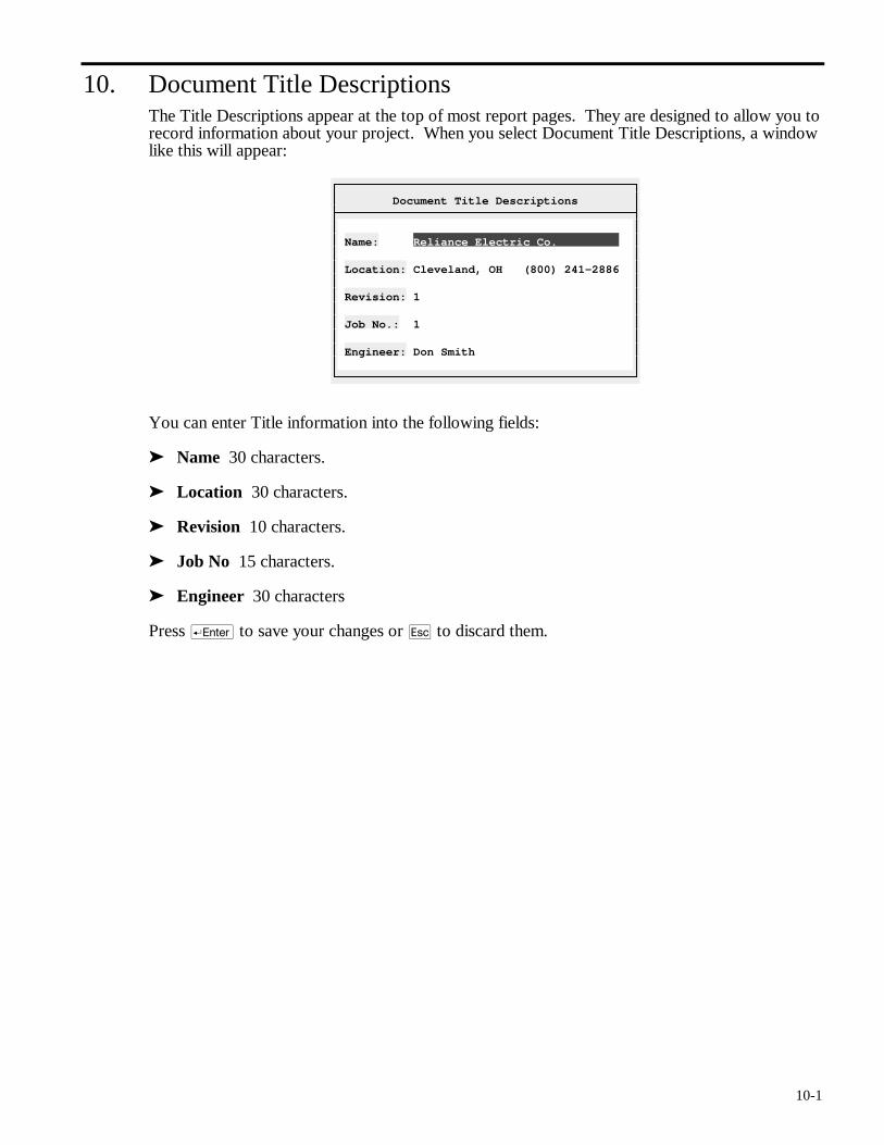
10-1
10. Document Title Descriptions The Title Descriptions appear at the top of most report pages. They are designed to allow you to record information about your project. When you select Document Title Descriptions, a window like this will appear:
Document Title Descriptions
Name: Reliance Electric Co. Location: Cleveland, OH (800) 241-2886 Revision: 1 Job No.: 1 Engineer: Don Smith
You can enter Title information into the following fields:
➤ Name 30 characters.
➤ Location 30 characters.
➤ Revision 10 characters.
➤ Job No 15 characters.
➤ Engineer 30 characters
Press r to save your changes or q to discard them.

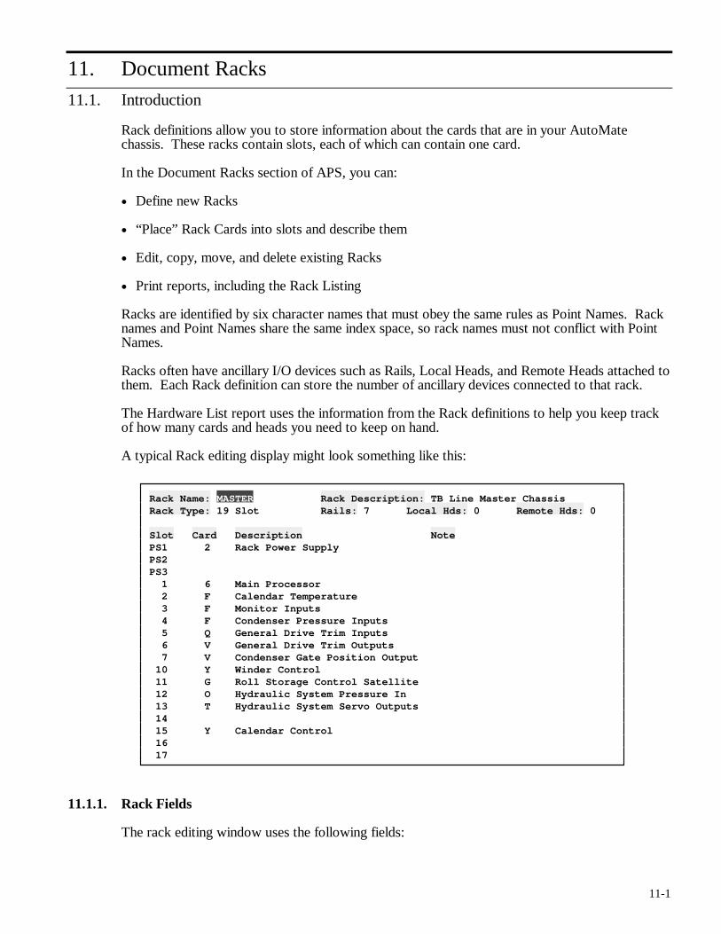
11-1
11. Document Racks
11.1. Introduction
Rack definitions allow you to store information about the cards that are in your AutoMate chassis. These racks contain slots, each of which can contain one card.
In the Document Racks section of APS, you can:
• Define new Racks
• “Place” Rack Cards into slots and describe them
• Edit, copy, move, and delete existing Racks
• Print reports, including the Rack Listing
Racks are identified by six character names that must obey the same rules as Point Names. Rack names and Point Names share the same index space, so rack names must not conflict with Point Names.
Racks often have ancillary I/O devices such as Rails, Local Heads, and Remote Heads attached to them. Each Rack definition can store the number of ancillary devices connected to that rack.
The Hardware List report uses the information from the Rack definitions to help you keep track of how many cards and heads you need to keep on hand.
A typical Rack editing display might look something like this:
Rack Name: MASTER Rack Description: TB Line Master Chassis Rack Type: 19 Slot Rails: 7 Local Hds: 0 Remote Hds: 0 Slot Card Description Note PS1 2 Rack Power Supply PS2 PS3 1 6 Main Processor 2 F Calendar Temperature 3 F Monitor Inputs 4 F Condenser Pressure Inputs 5 Q General Drive Trim Inputs 6 V General Drive Trim Outputs 7 V Condenser Gate Position Output 10 Y Winder Control 11 G Roll Storage Control Satellite 12 O Hydraulic System Pressure In 13 T Hydraulic System Servo Outputs 14 15 Y Calendar Control 16 17
11.1.1. Rack Fields
The rack editing window uses the following fields:
11-2
➤ Rack Name This is a six-character field. It must follow the same rules as a Point Name: it must begin with a letter and it must be unique. Since Rack names and Point Names share the same index space, you cannot use the same Name for a Rack and for a Point.
➤ Rack Description 30 characters.
➤ Rack Type [List Select] This is the size of the rack in slots. Choose from: 6 Slot, 8 Slot, 10 Slot, 13 Slot (Panel), 13 Slot (Cabinet), 16 Slot, and 19 Slot.
➤ Rails The number of Rails associated with this rack. This number is used in reports and in the Hardware List.
➤ Local Hds The number of Local Heads associated with this rack. This number is used in reports and in the Hardware List.
➤ Remote Hds The number of Remote Heads associated with this rack. This number is used in reports and in the Hardware List.
➤ Slot Fields Each slot consists of three fields:
• Card Code This field determines which Rack Card occupies the slot. Card codes go from 0 to 9, ‘A’ to ‘Z’, and ‘a’ to ‘h’. To select from a list of the current card definitions, press keypad (Grey) > while in the Card Code field.
• Card Description 30 characters.
• Card Note 30 characters.
Note: The Rack Type field above affects how the Slot Fields are interpreted. No matter what Rack Type is currently selected, you can fill in all of Slot Fields. However, when printing reports or calculating the Hardware List, APS will only consider the number of slots permitted by the Rack Type.
11.1.2. Shortcut Keys
The following shortcut keys are available in the Document Racks section:
Key Command
c + u Jump to previous Rack
c + G Jump to a particular Rack
c + v Jump to next Rack
c + d Cut contents of current field to paste buffer
a + d Delete the contents of the current field
a + i Paste the contents of the paste buffer into the current field.
c + i Copy the contents of the current field into the paste buffer.
The global function keys described in section 5.5. are also available.
11.2. The File Menu
The File Menu is available throughout APS. It is used to open new projects, go online, and so forth. The File Menu is described in section 6.
11-3
11.3. The Select Menu
Throughout APS, the Select menu is used to switch from one section of the program to another. To leave the Rack editor and switch to another APS section, press ) (or click the right mouse button) to summon the menu, then press S to pull down the Select menu. Choose the new section from the menu.
11.4. The Edit Menu
The Edit menu contains commands used to manipulate both individual card fields and entire Racks. Here are the Edit menu commands:
11.4.1. Cut
Shortcut key: c + d
This command “cuts” the current field to the paste buffer, a temporary storage area. You can “paste” the contents of this buffer into another field using the Paste command, described below.
11.4.2. Delete
Shortcut key: a + d
The Delete command clears the current field. The deleted text is lost.
11.4.3. Paste
Shortcut key: a + i
The Paste command “pastes” the contents of the paste buffer into the current field. The Edit / Paste command will be “greyed out” if there is nothing in the paste buffer. You can paste the same text repeatedly; the Paste buffer is not emptied by the Paste operation. Text will remain in the Paste buffer until it is replaced by another “Edit / Cut” or “Edit / Copy” command, or until you leave APS.
11.4.4. Change…
The “Edit / Change…” command is designed to search and replace text. For a description of the “Change…” command, please see section 8.4.4..
11.4.5. Copy
Shortcut key: c + i
The Copy command copies the contents of the current field to the paste buffer. The field is not altered.
11.4.6. Restore
Shortcut key: q
The Restorce command cancels changes to the current Rack after asking for confirmation. The Restore command can only cancel changes made since the last Select or Locate menu command.
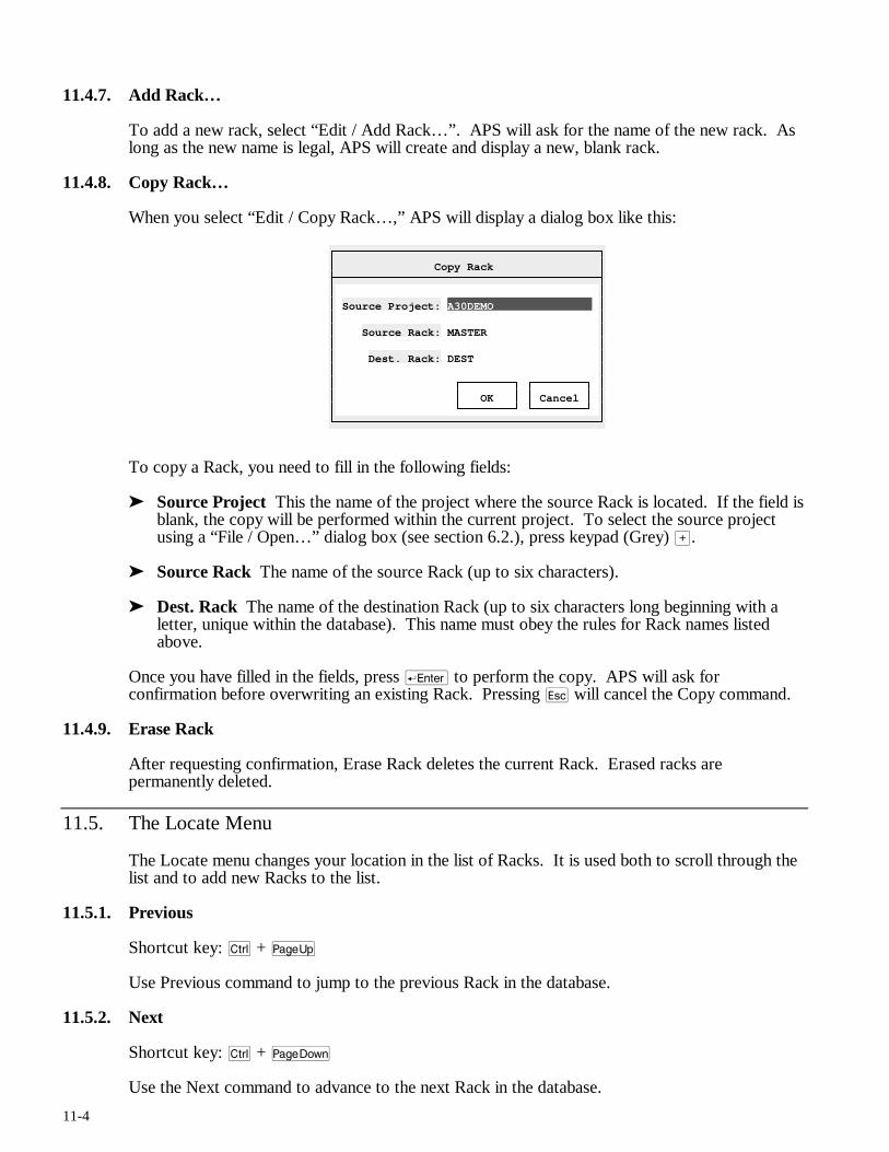
11-4
11.4.7. Add Rack…
To add a new rack, select “Edit / Add Rack…”. APS will ask for the name of the new rack. As long as the new name is legal, APS will create and display a new, blank rack.
11.4.8. Copy Rack…
When you select “Edit / Copy Rack…,” APS will display a dialog box like this:
Copy Rack
Source Project: A30DEMO Source Rack: MASTER Dest. Rack: DEST OK Cancel
To copy a Rack, you need to fill in the following fields:
➤ Source Project This the name of the project where the source Rack is located. If the field is blank, the copy will be performed within the current project. To select the source project using a “File / Open…” dialog box (see section 6.2.), press keypad (Grey) >.
➤ Source Rack The name of the source Rack (up to six characters).
➤ Dest. Rack The name of the destination Rack (up to six characters long beginning with a letter, unique within the database). This name must obey the rules for Rack names listed above.
Once you have filled in the fields, press r to perform the copy. APS will ask for confirmation before overwriting an existing Rack. Pressing q will cancel the Copy command.
11.4.9. Erase Rack
After requesting confirmation, Erase Rack deletes the current Rack. Erased racks are permanently deleted.
11.5. The Locate Menu
The Locate menu changes your location in the list of Racks. It is used both to scroll through the list and to add new Racks to the list.
11.5.1. Previous
Shortcut key: c + u
Use Previous command to jump to the previous Rack in the database.
11.5.2. Next
Shortcut key: c + v
Use the Next command to advance to the next Rack in the database.
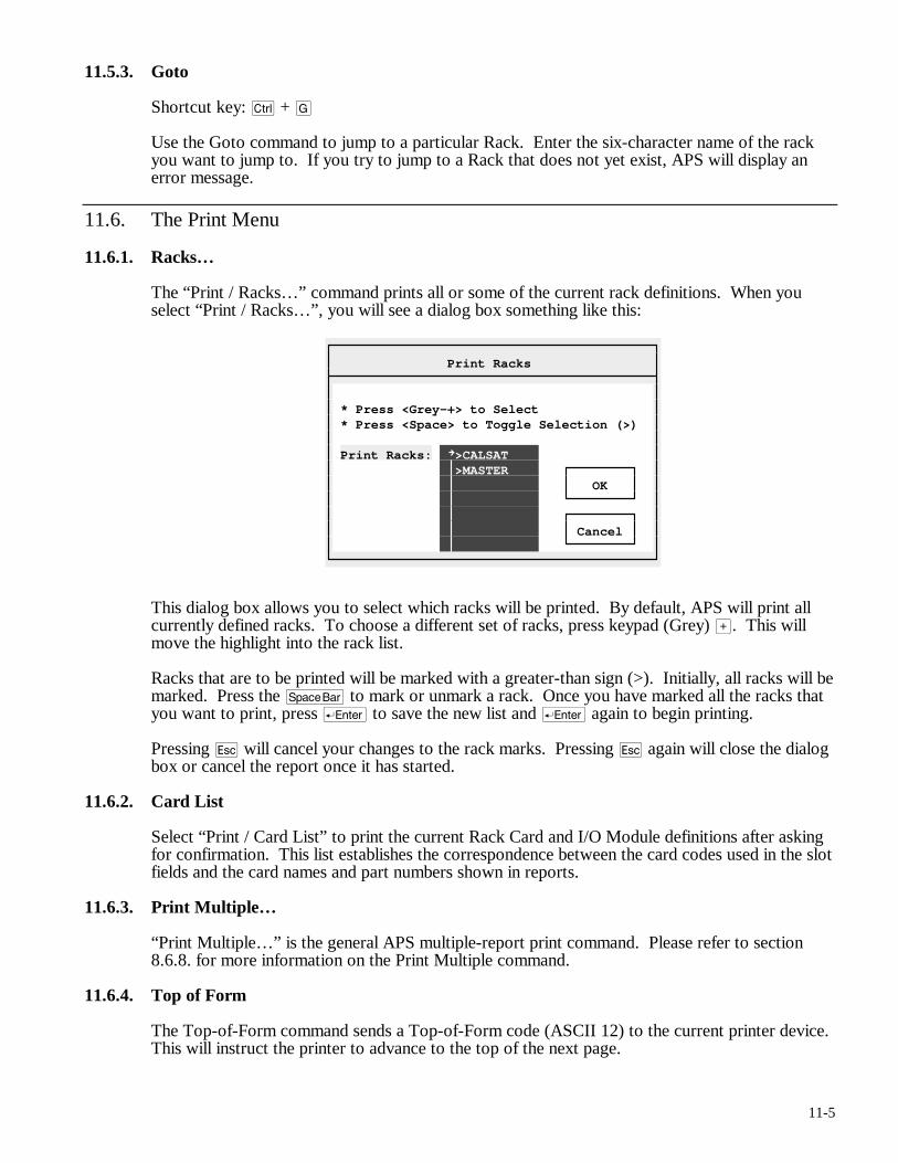
11-5
11.5.3. Goto
Shortcut key: c + G
Use the Goto command to jump to a particular Rack. Enter the six-character name of the rack you want to jump to. If you try to jump to a Rack that does not yet exist, APS will display an error message.
11.6. The Print Menu
11.6.1. Racks…
The “Print / Racks…” command prints all or some of the current rack definitions. When you select “Print / Racks…”, you will see a dialog box something like this:
Print Racks
* Press <Grey-+> to Select * Press <Space> to Toggle Selection (>) Print Racks: >CALSAT >MASTER OK Cancel
This dialog box allows you to select which racks will be printed. By default, APS will print all currently defined racks. To choose a different set of racks, press keypad (Grey) >. This will move the highlight into the rack list.
Racks that are to be printed will be marked with a greater-than sign (>). Initially, all racks will be marked. Press the y to mark or unmark a rack. Once you have marked all the racks that you want to print, press r to save the new list and r again to begin printing.
Pressing q will cancel your changes to the rack marks. Pressing q again will close the dialog box or cancel the report once it has started.
11.6.2. Card List
Select “Print / Card List” to print the current Rack Card and I/O Module definitions after asking for confirmation. This list establishes the correspondence between the card codes used in the slot fields and the card names and part numbers shown in reports.
11.6.3. Print Multiple…
“Print Multiple…” is the general APS multiple-report print command. Please refer to section 8.6.8. for more information on the Print Multiple command.
11.6.4. Top of Form
The Top-of-Form command sends a Top-of-Form code (ASCII 12) to the current printer device. This will instruct the printer to advance to the top of the next page.

12-1
12. The Sequence Editor
DANGER
ONLY QUALIFIED ELECTRICAL PERSONNEL FAMILIAR WITH THE CONSTRUCTION AND OPERATION OF THIS EQUIPMENT AND THE HAZARDS INVOLVED SHOULD INSTALL, ADJUST, OPERATE, AND/OR SERVICE IT. READ AND UNDERSTAND THE APPLICABLE MANUALS IN THEIR ENTIRETY BEFORE PROCEEDING. FAILURE TO OBSERVE THESE PRECAUTIONS COULD RESULT IN SEVERE BODILY INJURY OR LOSS OF LIFE.
WARNING
RELIANCE STRONGLY RECOMMENDS THE USE OF AN EXTERNAL, HARDWIRED EMERGENCY STOP CIRCUIT THAT WILL DISABLE THE SYSTEM IN CASE OF IMPROPER OPERATION. UNCONTROLLED MACHINE OPERATION MAY RESULT IF THIS PROCEDURE IS NOT FOLLOWED. FAILURE TO OBSERVE THIS PRECAUTION COULD RESULT IN BODILY INJURY.
The centerpiece of APS is the Sequence editor. You will use it to create and edit your ladder programs. From the Sequence editor section, you can:
• Insert new rungs
• Edit, copy, move, and delete existing rungs
• Import rungs from other programs
• Search the program for specific uses of points, registers, and block types
• “Search and Replace” contacts
• Insert repetitive rungs with the Macro command (see section 13.)
• Create and edit Drum tables (see section 14.)
• Print reports, including the Quick Ladder Listing, values of registers, usage of registers, and usage of coils
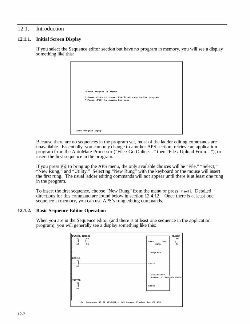
12-2
12.1. Introduction
12.1.1. Initial Screen Display
If you select the Sequence editor section but have no program in memory, you will see a display something like this:
Ladder Program is Empty. * Press <Ins> to insert the first rung in the program * Press <F10> to summon the menu. A30E Program Empty
Because there are no sequences in the program yet, most of the ladder editing commands are unavailable. Essentially, you can only change to another APS section, retrieve an application program from the AutoMate Processor (“File / Go Online…” then “File / Upload From…”), or insert the first sequence in the program.
If you press ) to bring up the APS menu, the only available choices will be “File,” “Select,” “New Rung,” and “Utility.” Selecting “New Rung” with the keyboard or the mouse will insert the first rung. The usual ladder editing commands will not appear until there is at least one rung in the program.
To insert the first sequence, choose “New Rung” from the menu or press i. Detailed directions for this command are found below in section 12.4.12.. Once there is at least one sequence in memory, you can use APS’s rung editing commands.
12.1.2. Basic Sequence Editor Operation
When you are in the Sequence editor (and there is at least one sequence in the application program), you will generally see a display something like this:
FLASHR INITZE FLASHR 40 40 40
/ Data Out ( ) .02 .03 SHBR .02 Length:5 RTC0.1 76
Shift .03 Table:2200 Value:1111100000000000INITZE 40
/ Reset .03 2> Sequence 40.02 (FLASHR): 1/2 Second Flasher for CP 430

12-3
The example above is a typical Sequence editor display. You will notice that it contains a typical SHBR block and an input circuit.
Each contact in the Sequence editor display looks something like this:
FLASHR 40
/ .02
There is the usual contact symbol (a Normally Closed contact in this case), the contact’s address (40.02), and the contact’s Name (FLASHR).
At the bottom of the screen, you can see the Sequence editor status line:
2> Sequence 40.02 (FLASHR): 1/2 Second Flasher for CP 430
The status line always starts out with the definition of the rung’s output coil, 40.02 in this case. It shows the coil’s Line Number (2), address (40.02), Name (FLASHR), and Point Description. If the coil had a Point Note, that would appear after the Point Description.
The flashing block cursor marks the current contact. You can move the cursor around with the arrow keys (ß, Í, ®, and Â). As you move the cursor, you will notice that the status line changes to reflect the definition of the current contact. For the contact 76.03 on the Shift input of the block, it might say something like:
4> • Contact 76.03 (RTC0.1) : System Clock 0.1 Sec
This means that the contact is on Line 4 (4>), its Name is (RTC0.1), and its Description is “System Clock 0.1 Sec”. This is the AutoMate 0.1 second system coil. Its Description and Name are added automatically when a new database is created.
To scroll through the program, you can use the u and v keys. You can also use the c + u and c + v keys.
Once you have moved the ladder that you want to edit (either using the Page keys or APS’s searching commands), you can use the ladder editing commands described below.
12.1.3. Editing Sequences Online
WARNING
WHEN REPLACING SEQUENCES IN THE ONLINE PROGRAMMING MODE, THERE WILL BE A PERIOD OF TIME WHEN NEITHER THE ORIGINAL SEQUENCE NOR THE NEW SEQUENCE WILL EXECUTE AND UNEXPECTED MACHINE MOVEMENT MAY RESULT. STATION A PERSON IN VIEW OF THE MACHINE AND WITH ACCESS TO AN EMERGENCY STOP SWITCH WHEN UTILIZING THIS MODE. FAILURE TO OBSERVE THESE PRECAUTIONS COULD RESULT IN BODILY INJURY.
To provide you with fastest possible searching, forcing, and editing while online, APS always keeps a copy of the current program in the computer’s memory. This means that APS can perform searches and edits to the local copy of the program, then update the copy in the Processor.
This strategy provides very quick searching, scrolling, monitoring, and editing. However, in order for APS’s online strategy to be effective, the copy of the application program in the computer’s memory must be identical to the copy in the AutoMate Processor. If the two copies differ, APS or the AutoMate program may operate erratically or report errors.
12-4
Every time you go online or alter a sequence, APS tests to make sure that the computer and AutoMate application programs are identical. It does this by comparing a “checksum” value in the AutoMate Processor’s memory to a locally-calculated value. If the two checksums do not match, APS will display a “Checksum Error” message box. Though APS will permit you to continue working, normally you should immediately use the “File / Upload (From)” or “File / Download (To)” commands to synchronize the two programs.
Note: The current Checksum status is also displayed in the Control Window (see section 7.1.).
You should rarely see Checksum Errors. The most likely cause of a checksum error is someone else editing the AutoMate application program without your knowledge. You will also get checksum errors if the AutoMate Processor has malfunctioned and erased its memory. In this case, you can download the program back into the Processor’s memory.
When you use the Sequence editor while online with the AutoMate Processor, APS will try to make changes both to the program in the Processor and to the program in your computer’s memory. This means that there is only one version of your application program.
Updating Sequences Online
Saving rung changes to the AutoMate Processor can take a long time, especially if the program is large. If APS seems to “freeze” when you are scrolling through the program while online, it is probably because APS is saving sequence changes to the AutoMate Processor.
APS will show a “Please Wait” message while it is updating the AutoMate Processor. If you have a large number of changes to make, it is often more efficient to make them offline and download them all at once.
WARNING
WHEN REPLACING SEQUENCES IN THE ONLINE PROGRAMMING MODE, THERE WILL BE A PERIOD OF TIME WHEN NEITHER THE ORIGINAL SEQUENCE NOR THE NEW SEQUENCE WILL EXECUTE AND UNEXPECTED MACHINE MOVEMENT MAY RESULT. STATION A PERSON IN VIEW OF THE MACHINE AND WITH ACCESS TO AN EMERGENCY STOP SWITCH WHEN UTILIZING THIS MODE. FAILURE TO OBSERVE THESE PRECAUTIONS COULD RESULT IN BODILY INJURY.
12.1.4. Uploading an Existing Application Program
You must always create a project before you can upload an existing application program from an AutoMate Processor. APS needs to have an existing “framework” available before it can accept a program from a Processor.
If you want to start editing an existing application program that is currently in an AutoMate Processor, you should create a new project with the proper AutoMate model, then use the “File / Upload (From)” command to retrieve the program. See section 6.1. for more information on creating a new project.
Once you have retrieved the program into the computer’s memory, you can begin making changes either online or offline. APS will not let you edit the program “directly” in the Processor’s memory: you must always start with a copy of the application program in the computer’s memory.
While online, APS simultaneously makes revisions to both the computer’s copy and the Processor’s copy of the program. Therefore, if you make online changes only with APS, you should never need to upload the program from the Processor (or Download it) again. Changes will always be reflected in both the computer and the Processor; when you leave APS, your changes will be saved to disk.
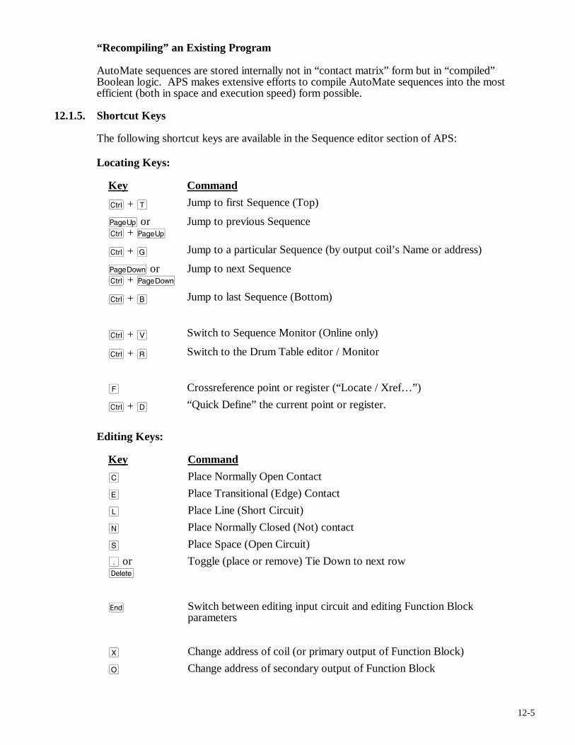
12-5
“Recompiling” an Existing Program
AutoMate sequences are stored internally not in “contact matrix” form but in “compiled” Boolean logic. APS makes extensive efforts to compile AutoMate sequences into the most efficient (both in space and execution speed) form possible.
12.1.5. Shortcut Keys
The following shortcut keys are available in the Sequence editor section of APS:
Locating Keys:
Key Command
c + T Jump to first Sequence (Top)
u orc + u
Jump to previous Sequence
c + G Jump to a particular Sequence (by output coil’s Name or address)
v or c + v
Jump to next Sequence
c + B Jump to last Sequence (Bottom)
c + V Switch to Sequence Monitor (Online only)
c + R Switch to the Drum Table editor / Monitor
F Crossreference point or register (“Locate / Xref…”)
c + D “Quick Define” the current point or register.
Editing Keys:
Key Command
C Place Normally Open Contact
E Place Transitional (Edge) Contact
L Place Line (Short Circuit)
N Place Normally Closed (Not) contact
S Place Space (Open Circuit)
. ord
Toggle (place or remove) Tie Down to next row
e Switch between editing input circuit and editing Function Block parameters
X Change address of coil (or primary output of Function Block)
O Change address of secondary output of Function Block
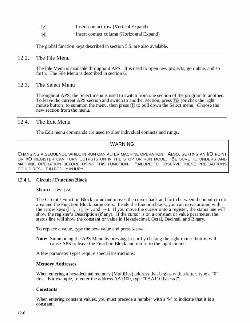
12-6
V Insert contact row (Vertical Expand)
H Insert contact column (Horizontal Expand)
The global function keys described in section 5.5. are also available.
12.2. The File Menu
The File Menu is available throughout APS. It is used to open new projects, go online, and so forth. The File Menu is described in section 6.
12.3. The Select Menu
Throughout APS, the Select menu is used to switch from one section of the program to another. To leave the current APS section and switch to another section, press ) (or click the right mouse button) to summon the menu, then press S to pull down the Select menu. Choose the new section from the menu.
12.4. The Edit Menu
The Edit menu commands are used to alter individual contacts and rungs.
WARNING
CHANGING A SEQUENCE WHILE IN RUN CAN ALTER MACHINE OPERATION. ALSO, SETTING AN I/O POINT OR I/O REGISTER CAN TURN OUTPUTS ON IN THE STOP OR RUN MODE. BE SURE TO UNDERSTAND MACHINE OPERATION BEFORE USING THIS FUNCTION. FAILURE TO OBSERVE THESE PRECAUTIONS COULD RESULT IN BODILY INJURY.
12.4.1. Circuit / Function Block
Shortcut key: e
The Circuit / Function Block command moves the cursor back and forth between the input circuit area and the Function Block parameters. Inside the function block, you can move around with the arrow keys (ß, Í, ®, and Â). If you move the cursor onto a register, the status line will show the register’s Description (if any). If the cursor is on a constant or value parameter, the status line will show the constant or value in Hexadecimal, Octal, Decimal, and Binary.
To replace a value, type the new value and press r.
Note: Summoning the APS Menu by pressing ) or by clicking the right mouse button will cause APS to leave the Function Block and return to the input circuit.
A few parameter types require special instructions:
Memory Addresses
When entering a hexadecimal memory (MultiBus) address that begins with a letter, type a “0” first. For example, to enter the address AA1100, type “0AA1100r”.
Constants
When entering constant values, you must precede a number with a ‘k’ to indicate that it is a constant.
12-7
If you wish to force an alternate input radix (number system base), you may enter a radix letter (D=Decimal, H=Hex, O=Octal, B=Binary, F=Floating Point) between the ‘k’ and the value itself. For example, type “k1000r” to enter 1000 in the default input radix for the current parameter.
To enter a hex constant, type something like “kh100Ar”. For Floating Point, enter “kf” followed by the value (and exponent, if any), for example: “kf1.25e10r”. Note that only a few blocks accept floating point constants.
Values
When editing a function block, it is possible to manually set register Value parameters. This effectively stores a value in the relevant data register.
For example, if you have used register 2000 as a Preset in a Timer block, you can enter a Value of 100. This will store 100 in the register. If you are on line, this will also write 100 into register 2000 on the AutoMate Processor. In offline mode, the value will be stored in the data space.
When offline, you can only store values in the data register range for the target Processor (not the I/O area). Values stored in this way will only be transferred if the program is downloaded to the Processor.
As for constants, you can specify the input radix of a value by preceding it with the proper code letter: D=Decimal, H=Hex, O=Octal, B=Binary, F=Floating Point. Note that Floating Point Values write two consecutive registers.
Slot / Channel
To enter a Slot:Channel address, precede it with a letter ‘N’. For example, “N4:2” will select slot 4, channel 2. Slot numbers are assumed to be in octal.
GOTO and GOSUB Addresses
When you enter a GOTO or GOSUB coil address, APS will verify that the target coil exists. If the target coil does not exist, a message will appear. Press any key to erase the message and continue editing.
Note: Before you download a program (or change a GOTO while online) to the AutoMate Processor, make sure that all GOTOs and GOSUBs refer to valid coil numbers. If you have GOTOs with nonexistent addresses in your program and put the Processor into Run mode, the results are unpredictable.
Elapsed Registers
When you enter a register address that will be used as an “Elapsed” register (in TON or TOFF for example), APS will search the program for other uses of the same register as an Elapsed register.
Usually, the application program will malfunction if two blocks are trying to use the same register to accumulate Elapsed values. Accordingly, if you have used the same register more than once as an Elapsed register, APS will display a message. Press any key to erase the message and continue editing.
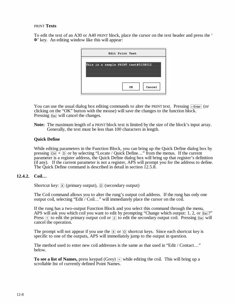
12-8
PRINT Texts
To edit the text of an A30 or A40 PRINT block, place the cursor on the text header and press the ‘✽’ key. An editing window like this will appear:
Edit Print Text
This is a sample PRINT text#015#012 OK Cancel
You can use the usual dialog box editing commands to alter the PRINT text. Pressing r (or clicking on the “OK” button with the mouse) will save the changes to the function block. Pressing q will cancel the changes.
Note: The maximum length of a PRINT block text is limited by the size of the block’s input array. Generally, the text must be less than 100 characters in length.
Quick Define
While editing parameters in the Function Block, you can bring up the Quick Define dialog box by pressing c + D or by selecting “Locate / Quick Define…” from the menus. If the current parameter is a register address, the Quick Define dialog box will bring up that register’s definition (if any). If the current parameter is not a register, APS will prompt you for the address to define. The Quick Define command is described in detail in section 12.5.8.
12.4.2. Coil…
Shortcut key: X (primary output), O (secondary output)
The Coil command allows you to alter the rung’s output coil address. If the rung has only one output coil, selecting “Edit / Coil…” will immediately place the cursor on the coil.
If the rung has a two-output Function Block and you select this command through the menu, APS will ask you which coil you want to edit by prompting “Change which output: 1, 2, or q?” Press 1 to edit the primary output coil or 2 to edit the secondary output coil. Pressing q will cancel the operation.
The prompt will not appear if you use the X or O shortcut keys. Since each shortcut key is specific to one of the outputs, APS will immediately jump to the output in question.
The method used to enter new coil addresses is the same as that used in “Edit / Contact…” below.
To see a list of Names, press keypad (Grey) > while editing the coil. This will bring up a scrollable list of currently defined Point Names.
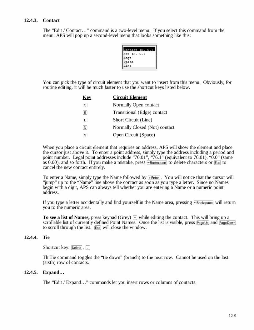
12-9
12.4.3. Contact
The “Edit / Contact…” command is a two-level menu. If you select this command from the menu, APS will pop up a second-level menu that looks something like this:
Contact (N. O.) Not (N. C.) Edge Space Line
You can pick the type of circuit element that you want to insert from this menu. Obviously, for routine editing, it will be much faster to use the shortcut keys listed below.
Key Circuit Element
C Normally Open contact
E Transitional (Edge) contact
L Short Circuit (Line)
N Normally Closed (Not) contact
S Open Circuit (Space)
When you place a circuit element that requires an address, APS will show the element and place the cursor just above it. To enter a point address, simply type the address including a period and point number. Legal point addresses include “76.01”, “76.1” (equivalent to 76.01), “0.0” (same as 0.00), and so forth. If you make a mistake, press b to delete characters or q to cancel the new contact entirely.
To enter a Name, simply type the Name followed by r. You will notice that the cursor will “jump” up to the “Name” line above the contact as soon as you type a letter. Since no Names begin with a digit, APS can always tell whether you are entering a Name or a numeric point address.
If you type a letter accidentally and find yourself in the Name area, pressing b will return you to the numeric area.
To see a list of Names, press keypad (Grey) > while editing the contact. This will bring up a scrollable list of currently defined Point Names. Once the list is visible, press u and v to scroll through the list. q will close the window.
12.4.4. Tie
Shortcut key: d, .
Th Tie command toggles the “tie down” (branch) to the next row. Cannot be used on the last (sixth) row of contacts.
12.4.5. Expand…
The “Edit / Expand…” commands let you insert rows or columns of contacts.
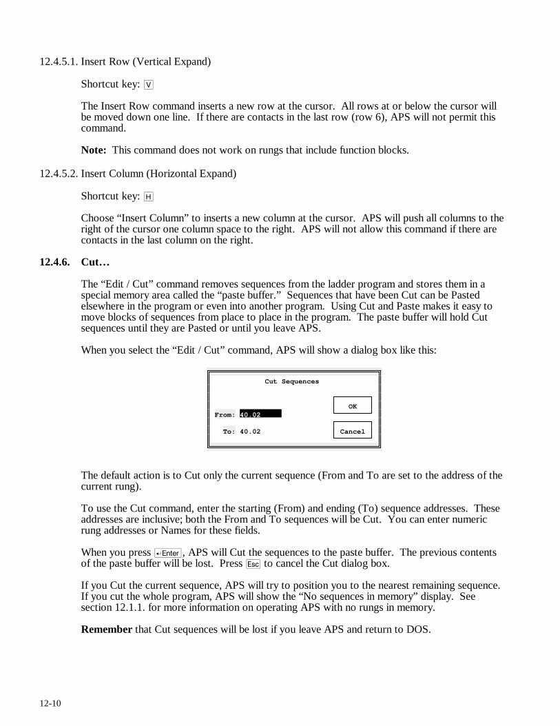
12-10
12.4.5.1. Insert Row (Vertical Expand)
Shortcut key: V
The Insert Row command inserts a new row at the cursor. All rows at or below the cursor will be moved down one line. If there are contacts in the last row (row 6), APS will not permit this command.
Note: This command does not work on rungs that include function blocks.
12.4.5.2. Insert Column (Horizontal Expand)
Shortcut key: H
Choose “Insert Column” to inserts a new column at the cursor. APS will push all columns to the right of the cursor one column space to the right. APS will not allow this command if there are contacts in the last column on the right.
12.4.6. Cut…
The “Edit / Cut” command removes sequences from the ladder program and stores them in a special memory area called the “paste buffer.” Sequences that have been Cut can be Pasted elsewhere in the program or even into another program. Using Cut and Paste makes it easy to move blocks of sequences from place to place in the program. The paste buffer will hold Cut sequences until they are Pasted or until you leave APS.
When you select the “Edit / Cut” command, APS will show a dialog box like this:
Cut Sequences OK From: 40.02 To: 40.02 Cancel
The default action is to Cut only the current sequence (From and To are set to the address of the current rung).
To use the Cut command, enter the starting (From) and ending (To) sequence addresses. These addresses are inclusive; both the From and To sequences will be Cut. You can enter numeric rung addresses or Names for these fields.
When you press r, APS will Cut the sequences to the paste buffer. The previous contents of the paste buffer will be lost. Press q to cancel the Cut dialog box.
If you Cut the current sequence, APS will try to position you to the nearest remaining sequence. If you cut the whole program, APS will show the “No sequences in memory” display. See section 12.1.1. for more information on operating APS with no rungs in memory.
Remember that Cut sequences will be lost if you leave APS and return to DOS.
12-11
12.4.7. Delete…
WARNING
DELETING A SEQUENCE WHILE IN RUN MAY ALTER MACHINE OPERATION. BE SURE TO UNDERSTAND MACHINE OPERATION BEFORE USING THIS FUNCTION. FAILURE TO OBSERVE THESE PRECAUTIONS COULD RESULT IN BODILY INJURY.
The “Edit / Delete…” command works in exactly the same way as the “Edit / Cut…” command (see above) except that Deleted sequences are permanently lost.
The “Edit / Delete…” command does not disturb the contents of the paste buffer.
12.4.8. Paste
The Paste command retrieves the current contents of the paste buffer into the current program below the current rung. The Paste command will be “greyed out” on the menu if the paste buffer is empty.
APS will ask for confirmation before Pasting sequences. It will also alert you if you are Pasting sequences that were created for another Processor model. Cross-model Pastes are not allowed, e.g., A30 to A40 or vice versa. You must use the Sequence editor “Edit / Copy…” command in this case.
Once you have used the Paste command, the paste buffer will be emptied.
Note: You cannot Paste while online.
Note: You cannot Paste into an empty program. If you wish to Paste an entire program, you must add a “dummy” rung, Paste the sequences, then delete the “dummy” rung.
12.4.9. Change…
The Sequence editor “Edit / Change…” command performs a “Search and Replace” operation on the ladder program. It will find every occurrence of a contact in a specified range of rungs and perform a user-selected operation on that contact.
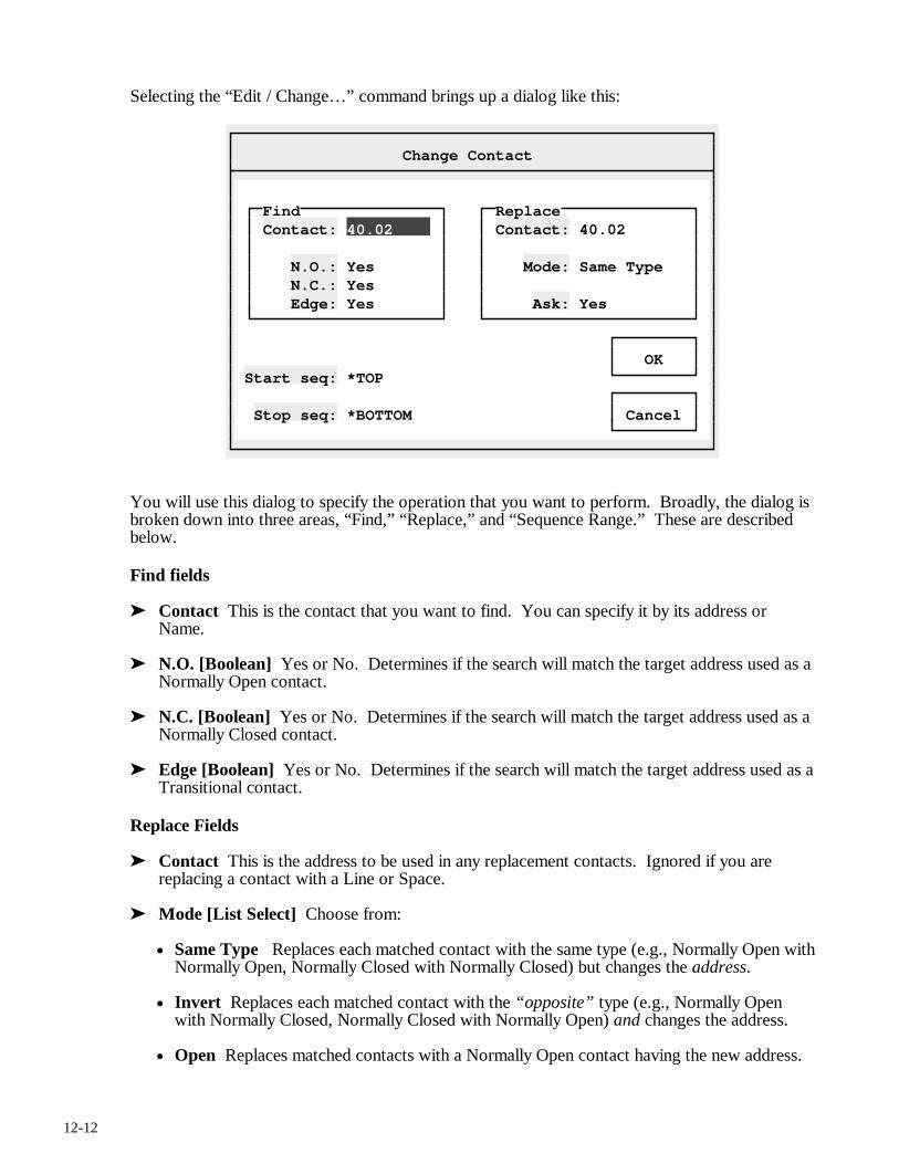
12-12
Selecting the “Edit / Change…” command brings up a dialog like this:
Change Contact
Find Replace Contact: 40.02 Contact: 40.02 N.O.: Yes Mode: Same Type N.C.: Yes Edge: Yes Ask: Yes OK Start seq: *TOP Stop seq: *BOTTOM Cancel
You will use this dialog to specify the operation that you want to perform. Broadly, the dialog is broken down into three areas, “Find,” “Replace,” and “Sequence Range.” These are described below.
Find fields
➤ Contact This is the contact that you want to find. You can specify it by its address or Name.
➤ N.O. [Boolean] Yes or No. Determines if the search will match the target address used as a Normally Open contact.
➤ N.C. [Boolean] Yes or No. Determines if the search will match the target address used as a Normally Closed contact.
➤ Edge [Boolean] Yes or No. Determines if the search will match the target address used as a Transitional contact.
Replace Fields
➤ Contact This is the address to be used in any replacement contacts. Ignored if you are replacing a contact with a Line or Space.
➤ Mode [List Select] Choose from:
• Same Type Replaces each matched contact with the same type (e.g., Normally Open with Normally Open, Normally Closed with Normally Closed) but changes the address.
• Invert Replaces each matched contact with the “opposite” type (e.g., Normally Open with Normally Closed, Normally Closed with Normally Open) and changes the address.
• Open Replaces matched contacts with a Normally Open contact having the new address.
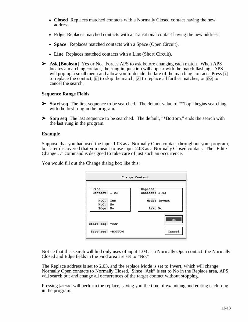
12-13
• Closed Replaces matched contacts with a Normally Closed contact having the new address.
• Edge Replaces matched contacts with a Transitional contact having the new address.
• Space Replaces matched contacts with a Space (Open Circuit).
• Line Replaces matched contacts with a Line (Short Circuit).
➤ Ask [Boolean] Yes or No. Forces APS to ask before changing each match. When APS locates a matching contact, the rung in question will appear with the match flashing. APS will pop up a small menu and allow you to decide the fate of the matching contact. Press Y to replace the contact, N to skip the match, A to replace all further matches, or q to cancel the search.
Sequence Range Fields
➤ Start seq The first sequence to be searched. The default value of “*Top” begins searching with the first rung in the program.
➤ Stop seq The last sequence to be searched. The default, “*Bottom,” ends the search with the last rung in the program.
Example
Suppose that you had used the input 1.03 as a Normally Open contact throughout your program, but later discovered that you meant to use input 2.03 as a Normally Closed contact. The “Edit / Change…” command is designed to take care of just such an occurrence.
You would fill out the Change dialog box like this:
Change Contact
Find Replace Contact: 1.03 Contact: 2.03 N.O.: Yes Mode: Invert N.C.: No Edge: No Ask: No OK Start seq: *TOP Stop seq: *BOTTOM Cancel
Notice that this search will find only uses of input 1.03 as a Normally Open contact: the Normally Closed and Edge fields in the Find area are set to “No.”
The Replace address is set to 2.03, and the replace Mode is set to Invert, which will change Normally Open contacts to Normally Closed. Since “Ask” is set to No in the Replace area, APS will search out and change all occurrences of the target contact without stopping.
Pressing r will perform the replace, saving you the time of examining and editing each rung in the program.
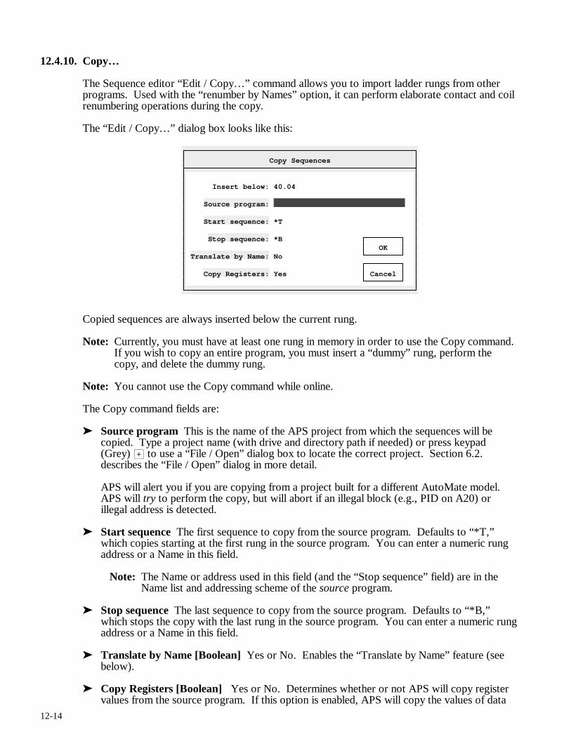
12-14
12.4.10. Copy…
The Sequence editor “Edit / Copy…” command allows you to import ladder rungs from other programs. Used with the “renumber by Names” option, it can perform elaborate contact and coil renumbering operations during the copy.
The “Edit / Copy…” dialog box looks like this:
Copy Sequences
Insert below: 40.04 Source program: Start sequence: *T Stop sequence: *B OK Translate by Name: No Copy Registers: Yes Cancel
Copied sequences are always inserted below the current rung.
Note: Currently, you must have at least one rung in memory in order to use the Copy command. If you wish to copy an entire program, you must insert a “dummy” rung, perform the copy, and delete the dummy rung.
Note: You cannot use the Copy command while online.
The Copy command fields are:
➤ Source program This is the name of the APS project from which the sequences will be copied. Type a project name (with drive and directory path if needed) or press keypad (Grey) > to use a “File / Open” dialog box to locate the correct project. Section 6.2. describes the “File / Open” dialog in more detail.
APS will alert you if you are copying from a project built for a different AutoMate model. APS will try to perform the copy, but will abort if an illegal block (e.g., PID on A20) or illegal address is detected.
➤ Start sequence The first sequence to copy from the source program. Defaults to “*T,” which copies starting at the first rung in the source program. You can enter a numeric rung address or a Name in this field.
Note: The Name or address used in this field (and the “Stop sequence” field) are in the Name list and addressing scheme of the source program.
➤ Stop sequence The last sequence to copy from the source program. Defaults to “*B,” which stops the copy with the last rung in the source program. You can enter a numeric rung address or a Name in this field.
➤ Translate by Name [Boolean] Yes or No. Enables the “Translate by Name” feature (see below).
➤ Copy Registers [Boolean] Yes or No. Determines whether or not APS will copy register values from the source program. If this option is enabled, APS will copy the values of data
12-15
registers used by Function Blocks from the source program into the current project’s data register space.
This option is most useful with blocks like DRUM, which use elaborate data tables stored in the register space. Copying a DRUM sequence with “Copy Registers” turned on will bring the associated Drum Table along during the copy. Note that copied register values will overwrite values already stored in the current project’s data register area.
Once you have filled in the Copy dialog box, press r and APS will begin preprocessing the source rungs. If it finds an illegal function block, address, or duplicate output coil in the source rungs, it will display a message and abort the copy.
APS will always ask for confirmation before inserting copied rungs. When the confirmation box appears, press r to insert the new rungs or N r to cancel the copy.
Translate by Names
If you enable the “Translate by Names” function, the Copy command will “translate” the sequences using Point Names. This means that the Name of each point reference in the source program will be checked in the target Point / Register Descriptions List before the insertion takes place.
For example, if point 44.10 has the Name LS100 in the source program and LS100 is the Name of point 14.01 in the destination program, any reference to point 44.10 in the source rungs will be translated to refer to 14.01 in the copied rungs.
If no match can be found, the point number will be passed unchanged.
This translate function permits you to do many things that would otherwise be very tedious. For example, suppose that you had to move a block of Digital I/O from one address to another. This would normally mean editing the entire program one rung at a time or repeated use of the Sequence editor’s “Edit / Change…” command.
The “Edit / Copy…” command could perform this change in one operation:
• Begin by making a copy of the source project (call it “S”) under a new name “D”. From DOS, you would type:
COPY S.* D.*r
• Use the Point / Register Description editor’s “Edit / Copy / Move” command to move the Digital I/O points to their new location in project D.
• Delete the entire program in project D
• Insert a dummy first rung
• Use the Sequence editor’s “Edit / Copy…” command (with “Translate via Names” enabled) to copy the entire program from project S.
• Remove the dummy first rung in the target project D
• Delete project S and rename project D as project S:
DEL S.*r REN D.* S.*r
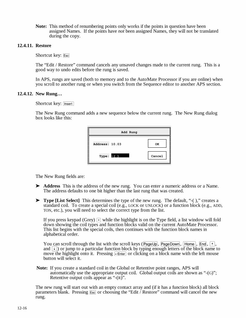
12-16
Note: This method of renumbering points only works if the points in question have been assigned Names. If the points have not been assigned Names, they will not be translated during the copy.
12.4.11. Restore
Shortcut key: q
The “Edit / Restore” command cancels any unsaved changes made to the current rung. This is a good way to undo edits before the rung is saved.
In APS, rungs are saved (both to memory and to the AutoMate Processor if you are online) when you scroll to another rung or when you switch from the Sequence editor to another APS section.
12.4.12. New Rung…
Shortcut key: i
The New Rung command adds a new sequence below the current rung. The New Rung dialog box looks like this:
Add Rung
Address: 10.03 OK Type: -( ) Cancel
The New Rung fields are:
➤ Address This is the address of the new rung. You can enter a numeric address or a Name. The address defaults to one bit higher than the last rung that was created.
➤ Type [List Select] This determines the type of the new rung. The default, “-( ),” creates a standard coil. To create a special coil (e.g., LOCK or UNLOCK) or a function block (e.g., ADD, TON, etc.), you will need to select the correct type from the list.
If you press keypad (Grey) > while the highlight is on the Type field, a list window will fold down showing the coil types and function blocks valid on the current AutoMate Processor. This list begins with the special coils, then continues with the function block names in alphabetical order.
You can scroll through the list with the scroll keys (u, v, m, e, ß, and Í) or jump to a particular function block by typing enough letters of the block name to move the highlight onto it. Pressing r or clicking on a block name with the left mouse button will select it.
Note: If you create a standard coil in the Global or Retentive point ranges, APS will automatically use the appropriate output coil. Global output coils are shown as “-(G)”; Retentive output coils appear as “-(R)”.
The new rung will start out with an empty contact array and (if it has a function block) all block parameters blank. Pressing q or choosing the “Edit / Restore” command will cancel the new rung.
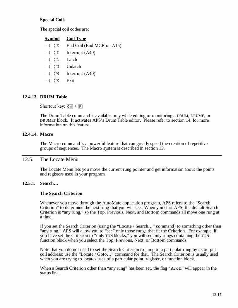
12-17
Special Coils
The special coil codes are:
Symbol Coil Type
-( )E End Coil (End MCR on A15)
-( )I Interrupt (A40)
-( )L Latch
-( )U Unlatch
-( )W Interrupt (A40)
-( )X Exit
12.4.13. DRUM Table
Shortcut key: c + R
The Drum Table command is available only while editing or monitoring a DRUM, DRUME, or DRUMET block. It activates APS’s Drum Table editor. Please refer to section 14. for more information on this feature.
12.4.14. Macro
The Macro command is a powerful feature that can greatly speed the creation of repetitive groups of sequences. The Macro system is described in section 13.
12.5. The Locate Menu
The Locate Menu lets you move the current rung pointer and get information about the points and registers used in your program.
12.5.1. Search…
The Search Criterion
Whenever you move through the AutoMate application program, APS refers to the “Search Criterion” to determine the next rung that you will see. When you start APS, the default Search Criterion is “any rung,” so the Top, Previous, Next, and Bottom commands all move one rung at a time.
If you set the Search Criterion (using the “Locate / Search…” command) to something other than “any rung,” APS will allow you to “see” only those rungs that fit the Criterion. For example, if you have set the Criterion to “only TON blocks,” you will see only rungs containing the TON function block when you select the Top, Previous, Next, or Bottom commands.
Note that you do not need to set the Search Criterion to jump to a particular rung by its output coil address; use the “Locate / Goto…” command for that. The Search Criterion is usually used when you are trying to locates uses of a particular point, register, or function block.
When a Search Criterion other than “any rung” has been set, the flag “Srch” will appear in the status line.
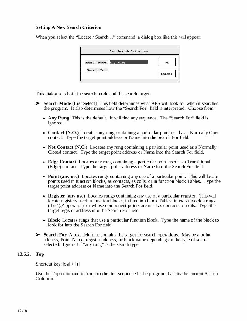
12-18
Setting A New Search Criterion
When you select the “Locate / Search…” command, a dialog box like this will appear:
Set Search Criterion
Search Mode: Any Rung OK Search For: Cancel
This dialog sets both the search mode and the search target:
➤ Search Mode [List Select] This field determines what APS will look for when it searches the program. It also determines how the “Search For” field is interpreted. Choose from:
• Any Rung This is the default. It will find any sequence. The “Search For” field is ignored.
• Contact (N.O.) Locates any rung containing a particular point used as a Normally Open contact. Type the target point address or Name into the Search For field.
• Not Contact (N.C.) Locates any rung containing a particular point used as a Normally Closed contact. Type the target point address or Name into the Search For field.
• Edge Contact Locates any rung containing a particular point used as a Transitional (Edge) contact. Type the target point address or Name into the Search For field.
• Point (any use) Locates rungs containing any use of a particular point. This will locate points used in function blocks, as contacts, as coils, or in function block Tables. Type the target point address or Name into the Search For field.
• Register (any use) Locates rungs containing any use of a particular register. This will locate registers used in function blocks, in function block Tables, in PRINT block strings (the ‘@’ operator), or whose component points are used as contacts or coils. Type the target register address into the Search For field.
• Block Locates rungs that use a particular function block. Type the name of the block to look for into the Search For field.
➤ Search For A text field that contains the target for search operations. May be a point address, Point Name, register address, or block name depending on the type of search selected. Ignored if “any rung” is the search type.
12.5.2. Top
Shortcut key: c + T
Use the Top command to jump to the first sequence in the program that fits the current Search Criterion.
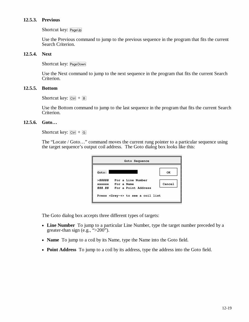
12-19
12.5.3. Previous
Shortcut key: u
Use the Previous command to jump to the previous sequence in the program that fits the current Search Criterion.
12.5.4. Next
Shortcut key: v
Use the Next command to jump to the next sequence in the program that fits the current Search Criterion.
12.5.5. Bottom
Shortcut key: c + B
Use the Bottom command to jump to the last sequence in the program that fits the current Search Criterion.
12.5.6. Goto…
Shortcut key: c + G
The “Locate / Goto…” command moves the current rung pointer to a particular sequence using the target sequence’s output coil address. The Goto dialog box looks like this:
Goto Sequence
Goto: OK >##### For a Line Number xxxxxx For a Name Cancel ###.## For a Point Address Press <Grey-+> to see a coil list
The Goto dialog box accepts three different types of targets:
• Line Number To jump to a particular Line Number, type the target number preceded by a greater-than sign (e.g., “>200”).
• Name To jump to a coil by its Name, type the Name into the Goto field.
• Point Address To jump to a coil by its address, type the address into the Goto field.
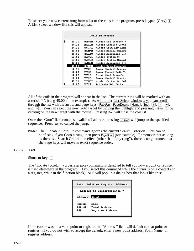
12-20
To select your new current rung from a list of the coils in the program, press keypad (Grey) >. A List Select window like this will appear:
Coils in Program
40.10 WHITEN Winder Web Tension > 44.14 TNCLON Winder Tension Contr 44.16 WTRIML Winder Trim Low Limi 40.04 WNDMAN Winder Manual Contro 40.05 WNDATO Winder Automatic Con 13.01 PL6001 Winder System ON 13.03 PL6003 Winder System Manual 41.03 WATRUN Winder Automatic Cyc 45.00* WDRMON Winder Drum Sequence 12.15 SV628 Lower Mandril Loader 12.07 SV636 Lower Thread Belt To 12.03 SV619 Close Mand Transfer 12.04 SV620 Lower Mandril Starte 41.11 CTONDY Winder Cutter On Del 12.05 SV621 Activate Web Cutter
All of the coils in the program will appear in the list. The current rung will be marked with an asterisk ‘*’, (rung 45.00 in the example). As with other List Select windows, you can scroll through the list with the arrow and page keys (u, v, m, e, ß, Í, ®, and Â). You can select the new Goto target by moving the highlight and pressing r or by clicking on the new target with the mouse. Pressing q will close the coil list.
Once the “Goto” field contains a valid coil address, pressing r will jump to the specified sequence. Press q to cancel the jump.
Note: The “Locate / Goto…” command ignores the current Search Criterion. This can be confusing if you Goto a rung, then press v (for example). Remember that as long as there is a Search Criterion in effect (other than “any rung”), there is no guarantee that the Page keys will move in exact sequence order.
12.5.7. Xref…
Shortcut key: F
The “Locate / Xref…” (crossreference) command is designed to tell you how a point or register is used elsewhere in the program. If you select this command while the cursor is on a contact (or a register, while in the function block), APS will pop up a dialog box that looks like this:
Enter Point or Register Address
Address to Crossreference ? Address: 40.02 xxxxxx Name ###.## Point Address ### Register Address
If the cursor was on a valid point or register, the “Address” field will default to that point or register. If you do not wish to accept the default, enter a new point address, Point Name, or register address.
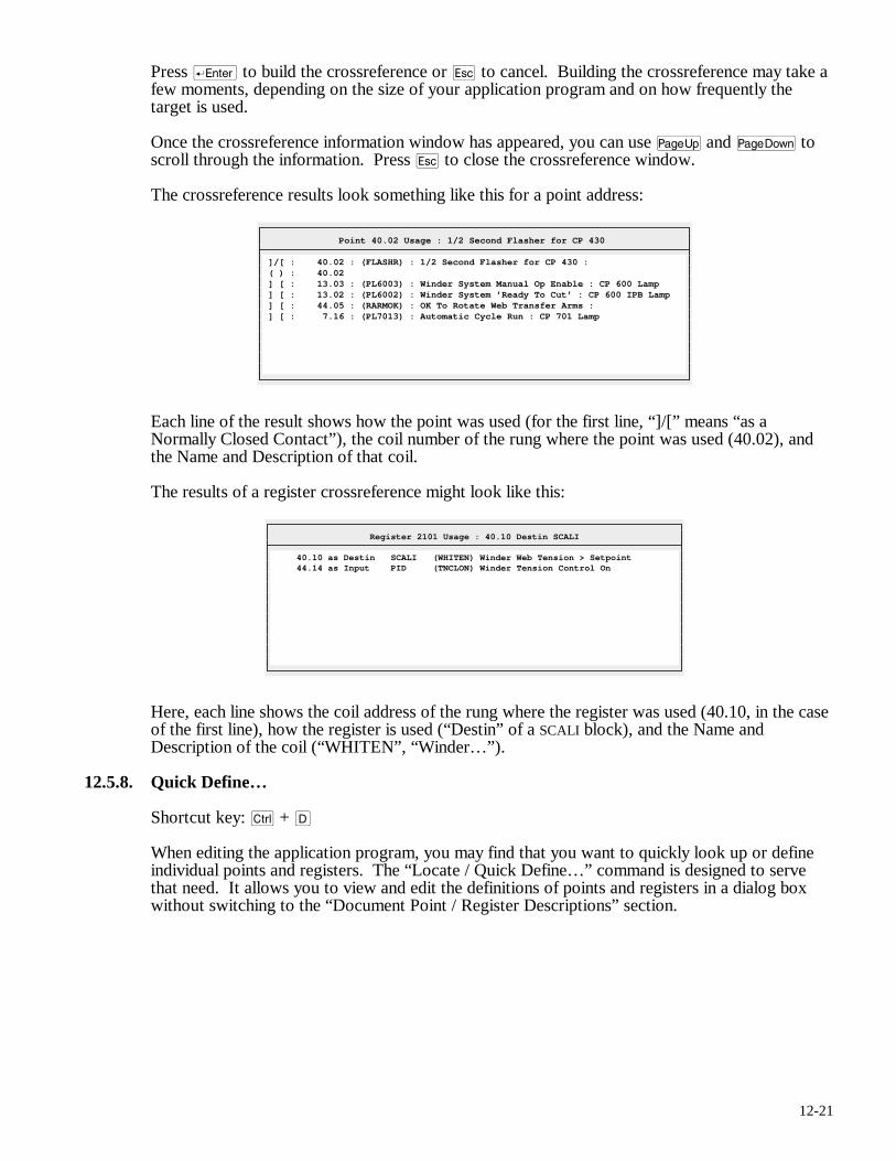
12-21
Press r to build the crossreference or q to cancel. Building the crossreference may take a few moments, depending on the size of your application program and on how frequently the target is used.
Once the crossreference information window has appeared, you can use u and v to scroll through the information. Press q to close the crossreference window.
The crossreference results look something like this for a point address:
Point 40.02 Usage : 1/2 Second Flasher for CP 430
]/[ : 40.02 : (FLASHR) : 1/2 Second Flasher for CP 430 : ( ) : 40.02 ] [ : 13.03 : (PL6003) : Winder System Manual Op Enable : CP 600 Lamp ] [ : 13.02 : (PL6002) : Winder System ’Ready To Cut’ : CP 600 IPB Lamp ] [ : 44.05 : (RARMOK) : OK To Rotate Web Transfer Arms : ] [ : 7.16 : (PL7013) : Automatic Cycle Run : CP 701 Lamp
Each line of the result shows how the point was used (for the first line, “]/[” means “as a Normally Closed Contact”), the coil number of the rung where the point was used (40.02), and the Name and Description of that coil.
The results of a register crossreference might look like this:
Register 2101 Usage : 40.10 Destin SCALI
40.10 as Destin SCALI (WHITEN) Winder Web Tension > Setpoint 44.14 as Input PID (TNCLON) Winder Tension Control On
Here, each line shows the coil address of the rung where the register was used (40.10, in the case of the first line), how the register is used (“Destin” of a SCALI block), and the Name and Description of the coil (“WHITEN”, “Winder…”).
12.5.8. Quick Define…
Shortcut key: c + D
When editing the application program, you may find that you want to quickly look up or define individual points and registers. The “Locate / Quick Define…” command is designed to serve that need. It allows you to view and edit the definitions of points and registers in a dialog box without switching to the “Document Point / Register Descriptions” section.
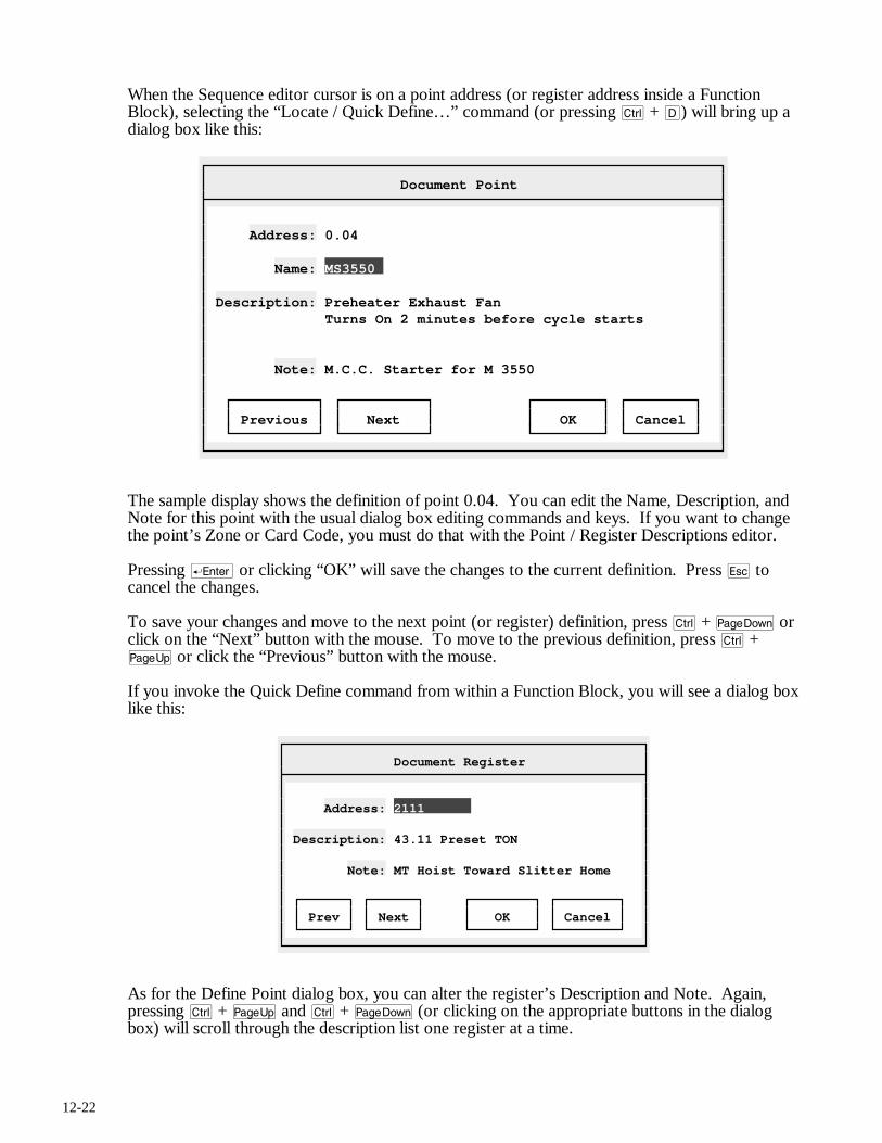
12-22
When the Sequence editor cursor is on a point address (or register address inside a Function Block), selecting the “Locate / Quick Define…” command (or pressing c + D) will bring up a dialog box like this:
Document Point
Address: 0.04 Name: MS3550 Description: Preheater Exhaust Fan Turns On 2 minutes before cycle starts Note: M.C.C. Starter for M 3550 Previous Next OK Cancel
The sample display shows the definition of point 0.04. You can edit the Name, Description, and Note for this point with the usual dialog box editing commands and keys. If you want to change the point’s Zone or Card Code, you must do that with the Point / Register Descriptions editor.
Pressing r or clicking “OK” will save the changes to the current definition. Press q to cancel the changes.
To save your changes and move to the next point (or register) definition, press c + v or click on the “Next” button with the mouse. To move to the previous definition, press c + u or click the “Previous” button with the mouse.
If you invoke the Quick Define command from within a Function Block, you will see a dialog box like this:
Document Register
Address: 2111 Description: 43.11 Preset TON Note: MT Hoist Toward Slitter Home Prev Next OK Cancel
As for the Define Point dialog box, you can alter the register’s Description and Note. Again, pressing c + u and c + v (or clicking on the appropriate buttons in the dialog box) will scroll through the description list one register at a time.
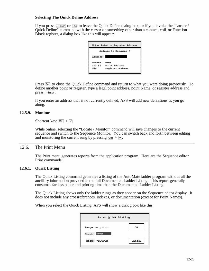
12-23
Selecting The Quick Define Address
If you press r or q to leave the Quick Define dialog box, or if you invoke the “Locate / Quick Define” command with the cursor on something other than a contact, coil, or Function Block register, a dialog box like this will appear:
Enter Point or Register Address
Address to Document ? Address: xxxxxx Name ###.## Point Address ### Register Address
Press q to close the Quick Define command and return to what you were doing previously. To define another point or register, type a legal point address, point Name, or register address and press r.
If you enter an address that is not currently defined, APS will add new definitions as you go along.
12.5.9. Monitor
Shortcut key: c + V
While online, selecting the “Locate / Monitor” command will save changes to the current sequence and switch to the Sequence Monitor. You can switch back and forth between editing and monitoring the current rung by pressing c + V.
12.6. The Print Menu
The Print menu generates reports from the application program. Here are the Sequence editor Print commands:
12.6.1. Quick Listing
The Quick Listing command generates a listing of the AutoMate ladder program without all the ancillary information provided in the full Documented Ladder Listing. This report generally consumes far less paper and printing time than the Documented Ladder Listing.
The Quick Listing shows only the ladder rungs as they appear on the Sequence editor display. It does not include any crossreferences, indexes, or documentation (except for Point Names).
When you select the Quick Listing, APS will show a dialog box like this:
Print Quick Listing
Range to print: OK Start: *TOP Stop: *BOTTOM Cancel
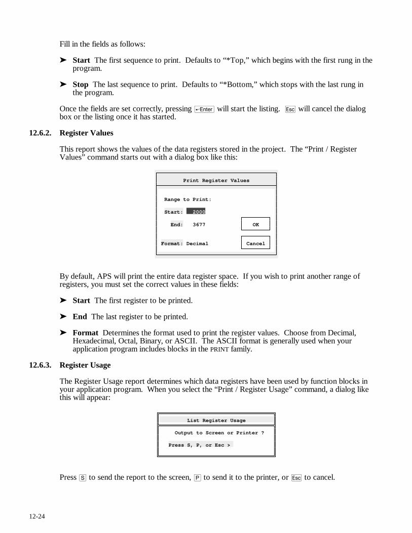
12-24
Fill in the fields as follows:
➤ Start The first sequence to print. Defaults to “*Top,” which begins with the first rung in the program.
➤ Stop The last sequence to print. Defaults to “*Bottom,” which stops with the last rung in the program.
Once the fields are set correctly, pressing r will start the listing. q will cancel the dialog box or the listing once it has started.
12.6.2. Register Values
This report shows the values of the data registers stored in the project. The “Print / Register Values” command starts out with a dialog box like this:
Print Register Values
Range to Print: Start: 2000 End: 3677 OK Format: Decimal Cancel
By default, APS will print the entire data register space. If you wish to print another range of registers, you must set the correct values in these fields:
➤ Start The first register to be printed.
➤ End The last register to be printed.
➤ Format Determines the format used to print the register values. Choose from Decimal, Hexadecimal, Octal, Binary, or ASCII. The ASCII format is generally used when your application program includes blocks in the PRINT family.
12.6.3. Register Usage
The Register Usage report determines which data registers have been used by function blocks in your application program. When you select the “Print / Register Usage” command, a dialog like this will appear:
List Register Usage
Output to Screen or Printer ? Press S, P, or Esc >
Press S to send the report to the screen, P to send it to the printer, or q to cancel.
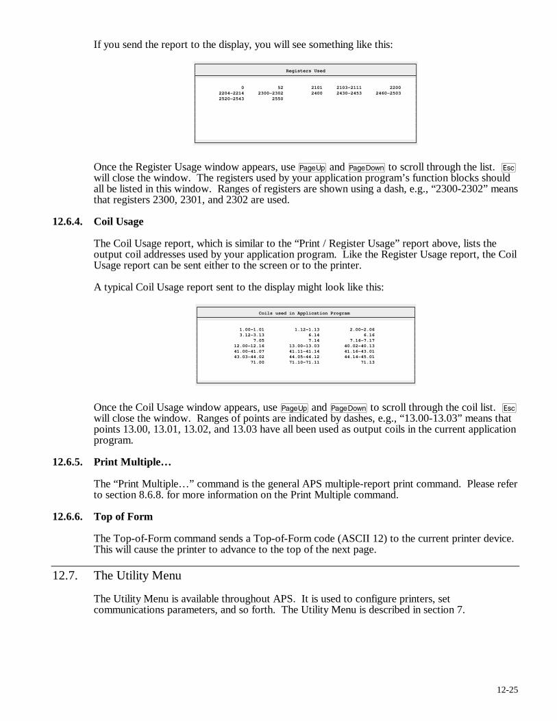
12-25
If you send the report to the display, you will see something like this:
Registers Used
0 52 2101 2103-2111 2200 2204-2214 2300-2302 2400 2430-2453 2460-2503 2520-2543 2550
Once the Register Usage window appears, use u and v to scroll through the list. q will close the window. The registers used by your application program’s function blocks should all be listed in this window. Ranges of registers are shown using a dash, e.g., “2300-2302” means that registers 2300, 2301, and 2302 are used.
12.6.4. Coil Usage
The Coil Usage report, which is similar to the “Print / Register Usage” report above, lists the output coil addresses used by your application program. Like the Register Usage report, the Coil Usage report can be sent either to the screen or to the printer.
A typical Coil Usage report sent to the display might look like this:
Coils used in Application Program
1.00-1.01 1.12-1.13 2.00-2.06 3.12-3.13 6.14 6.16 7.05 7.14 7.16-7.17 12.00-12.16 13.00-13.03 40.02-40.13 41.00-41.07 41.11-41.14 41.16-43.01 43.03-44.02 44.05-44.12 44.14-45.01 71.00 71.10-71.11 71.13
Once the Coil Usage window appears, use u and v to scroll through the coil list. q will close the window. Ranges of points are indicated by dashes, e.g., “13.00-13.03” means that points 13.00, 13.01, 13.02, and 13.03 have all been used as output coils in the current application program.
12.6.5. Print Multiple…
The “Print Multiple…” command is the general APS multiple-report print command. Please refer to section 8.6.8. for more information on the Print Multiple command.
12.6.6. Top of Form
The Top-of-Form command sends a Top-of-Form code (ASCII 12) to the current printer device. This will cause the printer to advance to the top of the next page.
12.7. The Utility Menu
The Utility Menu is available throughout APS. It is used to configure printers, set communications parameters, and so forth. The Utility Menu is described in section 7.

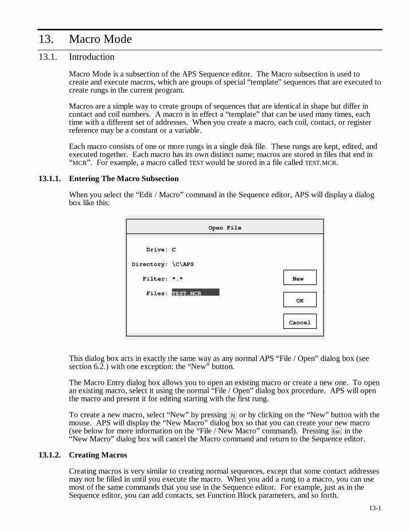
13-1
13. Macro Mode
13.1. Introduction
Macro Mode is a subsection of the APS Sequence editor. The Macro subsection is used to create and execute macros, which are groups of special “template” sequences that are executed to create rungs in the current program.
Macros are a simple way to create groups of sequences that are identical in shape but differ in contact and coil numbers. A macro is in effect a “template” that can be used many times, each time with a different set of addresses. When you create a macro, each coil, contact, or register reference may be a constant or a variable.
Each macro consists of one or more rungs in a single disk file. These rungs are kept, edited, and executed together. Each macro has its own distinct name; macros are stored in files that end in “MCR”. For example, a macro called TEST would be stored in a file called TEST.MCR.
13.1.1. Entering The Macro Subsection
When you select the “Edit / Macro” command in the Sequence editor, APS will display a dialog box like this:
Open File
Drive: C Directory: \C\APS Filter: *.* New Files: TEST.MCR OK Cancel
This dialog box acts in exactly the same way as any normal APS “File / Open” dialog box (see section 6.2.) with one exception: the “New” button.
The Macro Entry dialog box allows you to open an existing macro or create a new one. To open an existing macro, select it using the normal “File / Open” dialog box procedure. APS will open the macro and present it for editing starting with the first rung.
To create a new macro, select “New” by pressing N or by clicking on the “New” button with the mouse. APS will display the “New Macro” dialog box so that you can create your new macro (see below for more information on the “File / New Macro” command). Pressing q in the “New Macro” dialog box will cancel the Macro command and return to the Sequence editor.
13.1.2. Creating Macros
Creating macros is very similar to creating normal sequences, except that some contact addresses may not be filled in until you execute the macro. When you add a rung to a macro, you can use most of the same commands that you use in the Sequence editor. For example, just as in the Sequence editor, you can add contacts, set Function Block parameters, and so forth.
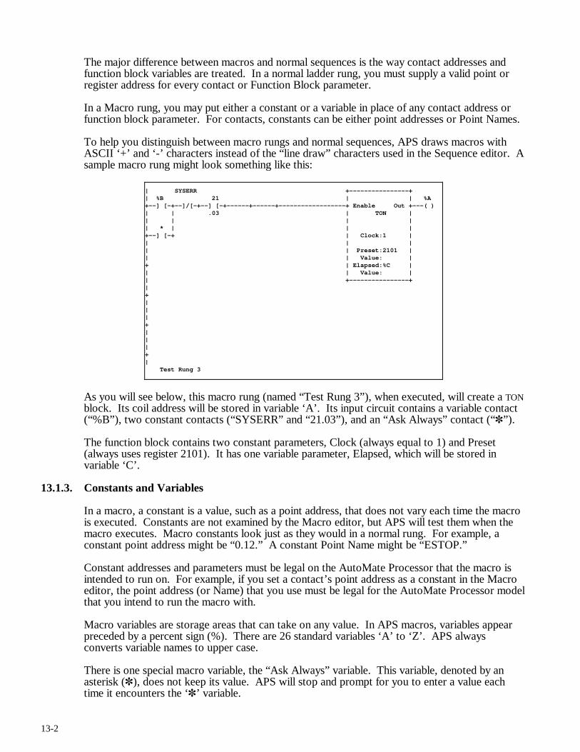
13-2
The major difference between macros and normal sequences is the way contact addresses and function block variables are treated. In a normal ladder rung, you must supply a valid point or register address for every contact or Function Block parameter.
In a Macro rung, you may put either a constant or a variable in place of any contact address or function block parameter. For contacts, constants can be either point addresses or Point Names.
To help you distinguish between macro rungs and normal sequences, APS draws macros with ASCII ‘+’ and ‘-’ characters instead of the “line draw” characters used in the Sequence editor. A sample macro rung might look something like this:
| SYSERR +----------------+ | %B 21 | | %A +--] [-+--]/[-+--] [-+------+------+------------------+ Enable Out +---( ) | | .03 | TON | | | | | | * | | | +--] [-+ | Clock:1 | | | | | | Preset:2101 | | | Value: | + | Elapsed:%C | | | Value: | | +----------------+ | + | | | + | | | + | Test Rung 3
As you will see below, this macro rung (named “Test Rung 3”), when executed, will create a TON block. Its coil address will be stored in variable ‘A’. Its input circuit contains a variable contact (“%B”), two constant contacts (“SYSERR” and “21.03”), and an “Ask Always” contact (“✽”).
The function block contains two constant parameters, Clock (always equal to 1) and Preset (always uses register 2101). It has one variable parameter, Elapsed, which will be stored in variable ‘C’.
13.1.3. Constants and Variables
In a macro, a constant is a value, such as a point address, that does not vary each time the macro is executed. Constants are not examined by the Macro editor, but APS will test them when the macro executes. Macro constants look just as they would in a normal rung. For example, a constant point address might be “0.12.” A constant Point Name might be “ESTOP.”
Constant addresses and parameters must be legal on the AutoMate Processor that the macro is intended to run on. For example, if you set a contact’s point address as a constant in the Macro editor, the point address (or Name) that you use must be legal for the AutoMate Processor model that you intend to run the macro with.
Macro variables are storage areas that can take on any value. In APS macros, variables appear preceded by a percent sign (%). There are 26 standard variables ‘A’ to ‘Z’. APS always converts variable names to upper case.
There is one special macro variable, the “Ask Always” variable. This variable, denoted by an asterisk (✽), does not keep its value. APS will stop and prompt for you to enter a value each time it encounters the ‘✽’ variable.
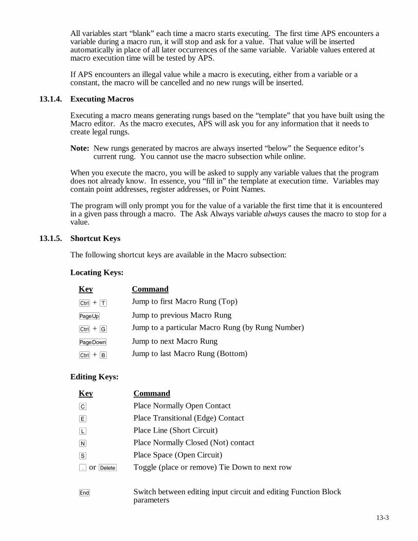
13-3
All variables start “blank” each time a macro starts executing. The first time APS encounters a variable during a macro run, it will stop and ask for a value. That value will be inserted automatically in place of all later occurrences of the same variable. Variable values entered at macro execution time will be tested by APS.
If APS encounters an illegal value while a macro is executing, either from a variable or a constant, the macro will be cancelled and no new rungs will be inserted.
13.1.4. Executing Macros
Executing a macro means generating rungs based on the “template” that you have built using the Macro editor. As the macro executes, APS will ask you for any information that it needs to create legal rungs.
Note: New rungs generated by macros are always inserted “below” the Sequence editor’s current rung. You cannot use the macro subsection while online.
When you execute the macro, you will be asked to supply any variable values that the program does not already know. In essence, you “fill in” the template at execution time. Variables may contain point addresses, register addresses, or Point Names.
The program will only prompt you for the value of a variable the first time that it is encountered in a given pass through a macro. The Ask Always variable always causes the macro to stop for a value.
13.1.5. Shortcut Keys
The following shortcut keys are available in the Macro subsection:
Locating Keys:
Key Command
c + T Jump to first Macro Rung (Top)
u Jump to previous Macro Rung
c + G Jump to a particular Macro Rung (by Rung Number)
v Jump to next Macro Rung
c + B Jump to last Macro Rung (Bottom)
Editing Keys:
Key Command
C Place Normally Open Contact
E Place Transitional (Edge) Contact
L Place Line (Short Circuit)
N Place Normally Closed (Not) contact
S Place Space (Open Circuit)
. or d Toggle (place or remove) Tie Down to next row
e Switch between editing input circuit and editing Function Block parameters
13-4
X Change address of coil (or primary output of Function Block)
O Change address of secondary output of Function Block
The global function keys described in section 5.5. are also available.
), as usual, summons the menu.
13.2. Return
Use the Return command to return to the Sequence editor from the Macro subsection. You will be asked if you want to save any changes that you may have made.
13.3. Macro
Macro menu commands manipulate the current macro (or allow you to create a new macro).
13.3.1. New
Selecting the “Macro / New” command will remove the current macro from memory. Before showing the “New Macro” dialog box, APS will allow you to save any changes you may have made to the current macro.
13.3.2. Open…
The “Macro / Open…” command retrieves an existing macro. This command uses a normal “File Open” dialog box as described in 6.2.
Before showing the “Open Macro” dialog box, APS will allow you to save any changes you may have made to the current macro. If you cancel the Open operation, APS will return you to the Sequence editor.
The Macro editor always starts by bringing up the first macro rung for editing.
13.3.3. Save
The Save command writes any changes to the current macro to disk. Any previous copy of the macro on disk will be lost.
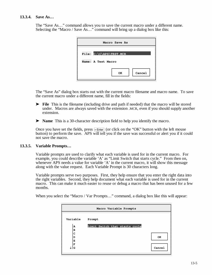
13-5
13.3.4. Save As…
The “Save As…” command allows you to save the current macro under a different name. Selecting the “Macro / Save As…” command will bring up a dialog box like this:
Macro Save As
File: C:\C\APS\TEST.MCR Name: A Test Macro OK Cancel
The “Save As” dialog box starts out with the current macro filename and macro name. To save the current macro under a different name, fill in the fields:
➤ File This is the filename (including drive and path if needed) that the macro will be stored under. Macros are always saved with the extension .MCR, even if you should supply another extension.
➤ Name This is a 30-character description field to help you identify the macro.
Once you have set the fields, press r (or click on the “OK” button with the left mouse button) to perform the save. APS will tell you if the save was successful or alert you if it could not save the macro.
13.3.5. Variable Prompts…
Variable prompts are used to clarify what each variable is used for in the current macro. For example, you could describe variable ‘A’ as “Limit Switch that starts cycle.” From then on, whenever APS needs a value for variable ‘A’ in the current macro, it will show this message along with the value request. Each Variable Prompt is 30 characters long.
Variable prompts serve two purposes. First, they help ensure that you enter the right data into the right variables. Second, they help document what each variable is used for in the current macro. This can make it much easier to reuse or debug a macro that has been unused for a few months.
When you select the “Macro / Var Prompts…” command, a dialog box like this will appear:
Macro Variable Prompts
Variable Prompt A Limit Switch that starts cycle B C D OK E F G Cancel
13-6
This dialog shows all 26 variables and their Variable Prompts in a scrollable list. In the sample dialog box, you can see that the variable ‘A’ has the prompt “Limit Switch that starts cycle.”
To set or view the variable prompts, you can scroll through the list with the arrow and page keys (u, v, m, e, ß, Í, ®, and Â). To replace an existing definition, simply type over it. To edit an existing definition, press keypad (Grey) >.
Once you have set the definitions, press r to save them or q to cancel. As usual, You can also click on the “OK” or “Cancel” buttons with the left mouse button.
13.3.6. Print…
The “Macro / Print…” command sends a copy of the current macro to the printer. When you select this command, APS will ask for a starting and ending rung. These default to the first and last rungs respectively.
Each macro rung is identified by a number. This number, which is simply the position of the rung in the macro, appears on the status line while you are editing the rung.
Set the desired starting and ending rungs and press r to start the report. Pressing q will cancel the dialog box or the report once it has started. The Macro Listing includes a printed copy of each rung in the macro and a copy of the Variable Prompts table.
13.3.7. Execute
Shortcut key: c + X
Use the Execute command to begin executing a macro. Ladder sequences generated will be inserted after the current Sequence editor program pointer.
The rungs will seem to go by very quickly, stopping only when APS needs a variable value from the user. If a rung cannot be assembled, the entire macro operation will abort.
Each time a new variable value is needed, the Variable Prompt set with the “Macro / Var Prompts…” command will appear. Type the correct variable value followed by r. The variable will automatically be filled in through the rest of the macro. Pressing q will cancel the macro.
All variables are reset at the start of each “Macro / Execute” command. The rungs created by the “Macro / Execute” command will only be inserted into the application program if the macro runs completely through to the end. If the macro fails, or if you cancel it with the q key, the partially-completed rungs will be lost.
13.4. Edit
The Edit menu contains commands used to create and alter Macro rungs.
13.4.1. Circuit / Function Block
Shortcut key: e
The Circuit / Function Block command moves the cursor back and forth between the input circuit area and the Function Block parameters. Inside the function block, you can move around with the arrow keys (ß, Í, ®, and Â).
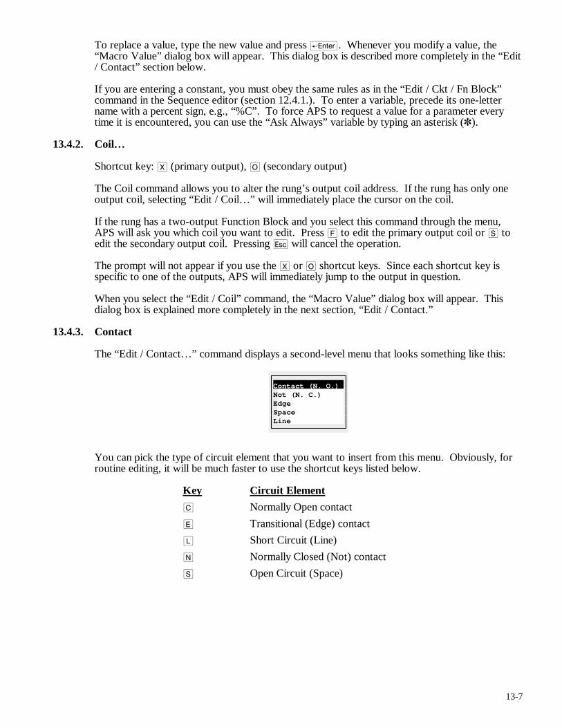
13-7
To replace a value, type the new value and press r. Whenever you modify a value, the “Macro Value” dialog box will appear. This dialog box is described more completely in the “Edit / Contact” section below.
If you are entering a constant, you must obey the same rules as in the “Edit / Ckt / Fn Block” command in the Sequence editor (section 12.4.1.). To enter a variable, precede its one-letter name with a percent sign, e.g., “%C”. To force APS to request a value for a parameter every time it is encountered, you can use the “Ask Always” variable by typing an asterisk (✽).
13.4.2. Coil…
Shortcut key: X (primary output), O (secondary output)
The Coil command allows you to alter the rung’s output coil address. If the rung has only one output coil, selecting “Edit / Coil…” will immediately place the cursor on the coil.
If the rung has a two-output Function Block and you select this command through the menu, APS will ask you which coil you want to edit. Press F to edit the primary output coil or S to edit the secondary output coil. Pressing q will cancel the operation.
The prompt will not appear if you use the X or O shortcut keys. Since each shortcut key is specific to one of the outputs, APS will immediately jump to the output in question.
When you select the “Edit / Coil” command, the “Macro Value” dialog box will appear. This dialog box is explained more completely in the next section, “Edit / Contact.”
13.4.3. Contact
The “Edit / Contact…” command displays a second-level menu that looks something like this:
Contact (N. O.) Not (N. C.) Edge Space Line
You can pick the type of circuit element that you want to insert from this menu. Obviously, for routine editing, it will be much faster to use the shortcut keys listed below.
Key Circuit Element
C Normally Open contact
E Transitional (Edge) contact
L Short Circuit (Line)
N Normally Closed (Not) contact
S Open Circuit (Space)
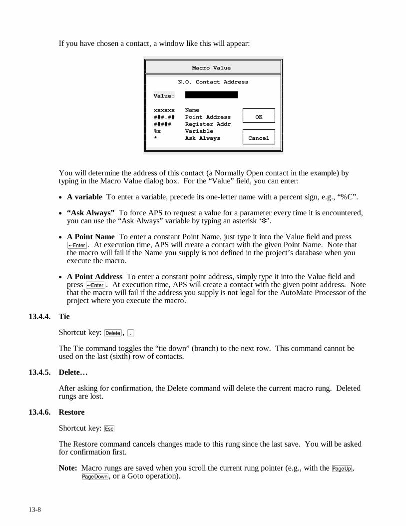
13-8
If you have chosen a contact, a window like this will appear:
Macro Value
N.O. Contact Address Value: xxxxxx Name ###.## Point Address OK ##### Register Addr %x Variable * Ask Always Cancel
You will determine the address of this contact (a Normally Open contact in the example) by typing in the Macro Value dialog box. For the “Value” field, you can enter:
• A variable To enter a variable, precede its one-letter name with a percent sign, e.g., “%C”.
• “Ask Always” To force APS to request a value for a parameter every time it is encountered, you can use the “Ask Always” variable by typing an asterisk ‘✽’.
• A Point Name To enter a constant Point Name, just type it into the Value field and press r. At execution time, APS will create a contact with the given Point Name. Note that the macro will fail if the Name you supply is not defined in the project’s database when you execute the macro.
• A Point Address To enter a constant point address, simply type it into the Value field and press r. At execution time, APS will create a contact with the given point address. Note that the macro will fail if the address you supply is not legal for the AutoMate Processor of the project where you execute the macro.
13.4.4. Tie
Shortcut key: d, .
The Tie command toggles the “tie down” (branch) to the next row. This command cannot be used on the last (sixth) row of contacts.
13.4.5. Delete…
After asking for confirmation, the Delete command will delete the current macro rung. Deleted rungs are lost.
13.4.6. Restore
Shortcut key: q
The Restore command cancels changes made to this rung since the last save. You will be asked for confirmation first.
Note: Macro rungs are saved when you scroll the current rung pointer (e.g., with the u, v, or a Goto operation).
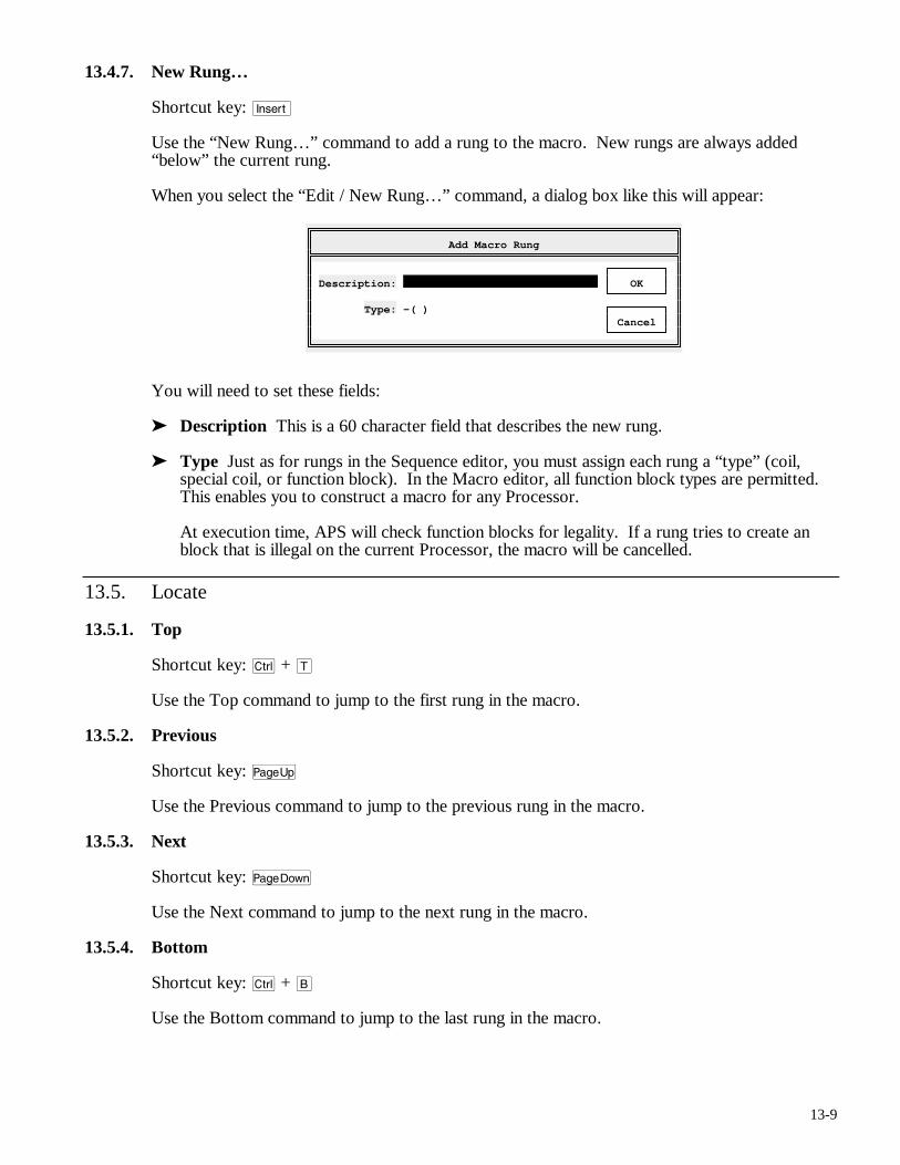
13-9
13.4.7. New Rung…
Shortcut key: i
Use the “New Rung…” command to add a rung to the macro. New rungs are always added “below” the current rung.
When you select the “Edit / New Rung…” command, a dialog box like this will appear:
Add Macro Rung
Description: OK Type: -( ) Cancel
You will need to set these fields:
➤ Description This is a 60 character field that describes the new rung.
➤ Type Just as for rungs in the Sequence editor, you must assign each rung a “type” (coil, special coil, or function block). In the Macro editor, all function block types are permitted. This enables you to construct a macro for any Processor.
At execution time, APS will check function blocks for legality. If a rung tries to create an block that is illegal on the current Processor, the macro will be cancelled.
13.5. Locate
13.5.1. Top
Shortcut key: c + T
Use the Top command to jump to the first rung in the macro.
13.5.2. Previous
Shortcut key: u
Use the Previous command to jump to the previous rung in the macro.
13.5.3. Next
Shortcut key: v
Use the Next command to jump to the next rung in the macro.
13.5.4. Bottom
Shortcut key: c + B
Use the Bottom command to jump to the last rung in the macro.

13-10
13.5.5. Goto…
Shortcut key: c + G
The “Locate / Goto…” command moves the current rung pointer to a particular rung in the macro by the rung number.
Pressing r will jump to the specified rung. Press q to cancel the jump.
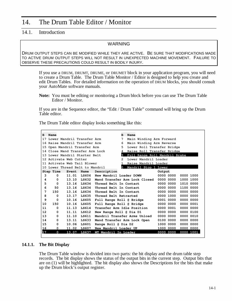
14-1
14. The Drum Table Editor / Monitor
14.1. Introduction
WARNING
DRUM OUTPUT STEPS CAN BE MODIFIED WHILE THEY ARE ACTIVE. BE SURE THAT MODIFICATIONS MADE TO ACTIVE DRUM OUTPUT STEPS WILL NOT RESULT IN UNEXPECTED MACHINE MOVEMENT. FAILURE TO OBSERVE THESE PRECAUTIONS COULD RESULT IN BODILY INJURY.
If you use a DRUM, DRUMT, DRUME, or DRUMET block in your application program, you will need to create a Drum Table. The Drum Table Monitor / Editor is designed to help you create and edit Drum Tables. For detailed information on the operation of DRUM blocks, you should consult your AutoMate software manuals.
Note: You must be editing or monitoring a Drum block before you can use The Drum Table Editor / Monitor.
If you are in the Sequence editor, the “Edit / Drum Table” command will bring up the Drum Table editor.
The Drum Table editor display looks something like this:
B Name B Name 17 Lower Mandril Transfer Arm 7 Main Winding Arm Forward 16 Raise Mandril Transfer Arm 6 Main Winding Arm Reverse 15 Open Mandril Transfer Arm 5 Lower Roll Transfer Bridge 14 Close Mand Transfer Arm Lock 4 Raise Roll Transfer Bridge 13 Lower Mandril Starter Belt 3 Full Range Roll Mandril Brake 12 Activate Web Cutter 2 Lower Mandril Loader 11 Activate Web Tail Blower 1 Raise Mandril Loader 10 Lower Thread Belt to Mandril 0 Mandril Stop 1 Lower Step Time Event Name Description Output 3 0 11.01 LS606 New Mandril Loader DOWN 0000 0000 0000 1000 4 0 13.10 LS632 Mand Transfer Arm Lock Closed 0000 0000 1000 1000 5 0 13.16 LS634 Thread Belt In Contact 0000 0000 1010 0000 6 50 13.16 LS634 Thread Belt In Contact 0000 0000 1100 0000 7 150 13.16 LS634 Thread Belt In Contact 0000 0000 0000 0000 8 0 13.17 LS635 Thread Belt Retracted 0000 1000 0000 0000 9 0 10.16 LS605 Full Range Roll @ Bridge 0001 0000 0000 0000 10 150 10.16 LS605 Full Range Roll @ Bridge 0000 0000 0000 0001 11 0 11.13 LS614 Transfer Arm Idle Position 0000 0001 0000 0000 12 0 11.11 LS612 New Range Roll @ Dia D1 0000 0000 0000 0100 13 0 11.10 LS611 Mandril Transfer Arms Unload 0000 0000 0000 0010 14 0 13.11 LS633 Mand Transfer Arm Lock Open 0100 0000 0000 0000 15 0 10.06 LS601 Range Roll @ Dia D2 1000 0000 0000 0000 16 0 11.02 LS607 New Mandril Loader UP 1000 0000 0000 0000 17 0 13.07 LS637 MT Mandril In Loader 0000 0000 0000 1001
14.1.1. The Bit Display
The Drum Table window is divided into two parts: the bit display and the drum table step records. The bit display shows the status of the output bits in the current step. Output bits that are on (1) will be highlighted. The bit display also shows the Descriptions for the bits that make up the Drum block’s output register.
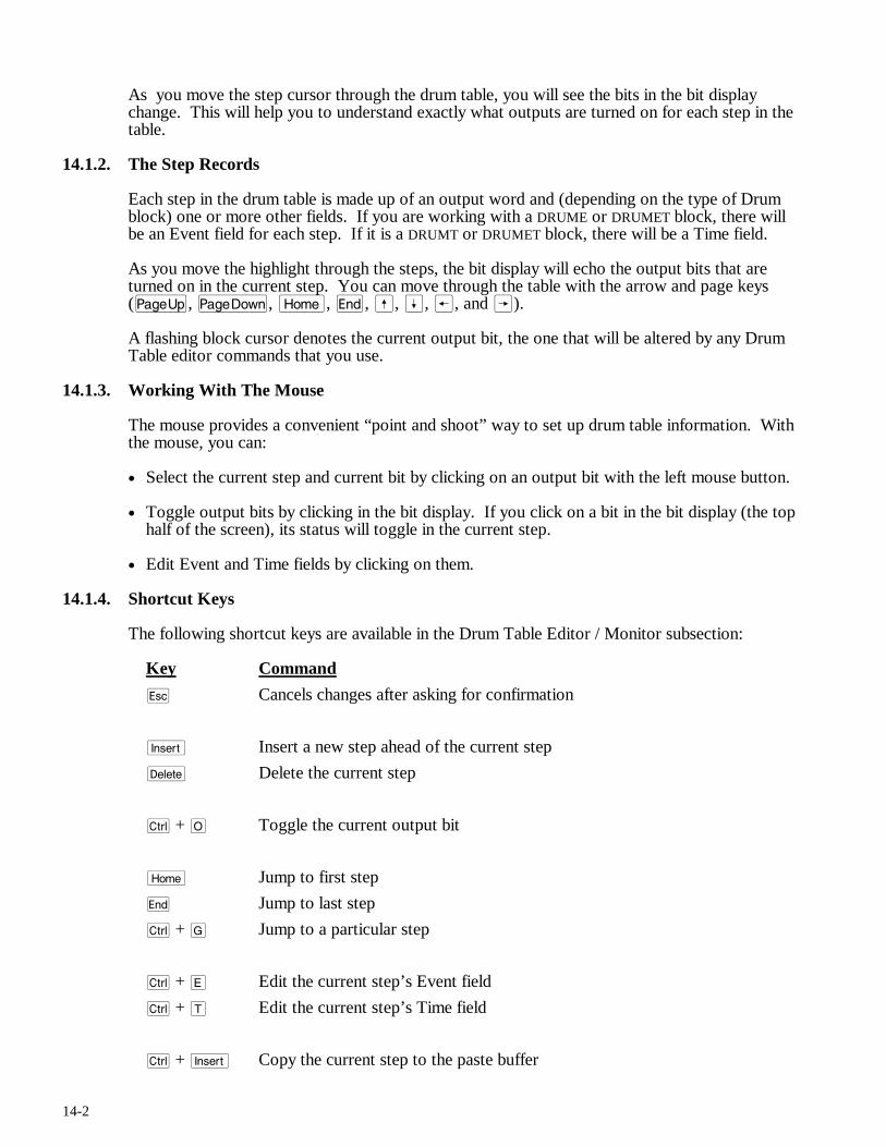
14-2
As you move the step cursor through the drum table, you will see the bits in the bit display change. This will help you to understand exactly what outputs are turned on for each step in the table.
14.1.2. The Step Records
Each step in the drum table is made up of an output word and (depending on the type of Drum block) one or more other fields. If you are working with a DRUME or DRUMET block, there will be an Event field for each step. If it is a DRUMT or DRUMET block, there will be a Time field.
As you move the highlight through the steps, the bit display will echo the output bits that are turned on in the current step. You can move through the table with the arrow and page keys (u, v, m, e, ß, Í, ®, and Â).
A flashing block cursor denotes the current output bit, the one that will be altered by any Drum Table editor commands that you use.
14.1.3. Working With The Mouse
The mouse provides a convenient “point and shoot” way to set up drum table information. With the mouse, you can:
• Select the current step and current bit by clicking on an output bit with the left mouse button.
• Toggle output bits by clicking in the bit display. If you click on a bit in the bit display (the top half of the screen), its status will toggle in the current step.
• Edit Event and Time fields by clicking on them.
14.1.4. Shortcut Keys
The following shortcut keys are available in the Drum Table Editor / Monitor subsection:
Key Command
q Cancels changes after asking for confirmation
i Insert a new step ahead of the current step
d Delete the current step
c + O Toggle the current output bit
m Jump to first step
e Jump to last step
c + G Jump to a particular step
c + E Edit the current step’s Event field
c + T Edit the current step’s Time field
c + i Copy the current step to the paste buffer
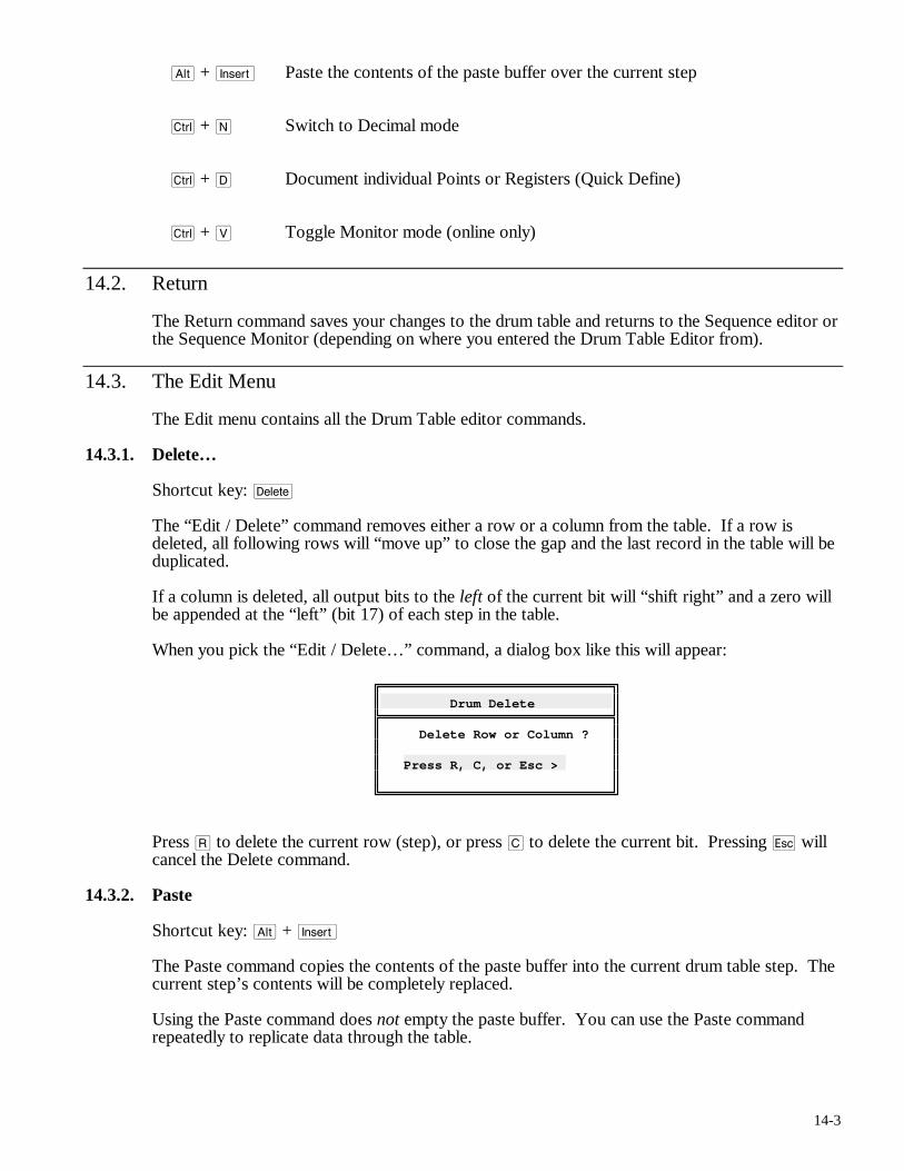
14-3
a + i Paste the contents of the paste buffer over the current step
c + N Switch to Decimal mode
c + D Document individual Points or Registers (Quick Define)
c + V Toggle Monitor mode (online only)
14.2. Return
The Return command saves your changes to the drum table and returns to the Sequence editor or the Sequence Monitor (depending on where you entered the Drum Table Editor from).
14.3. The Edit Menu
The Edit menu contains all the Drum Table editor commands.
14.3.1. Delete…
Shortcut key: d
The “Edit / Delete” command removes either a row or a column from the table. If a row is deleted, all following rows will “move up” to close the gap and the last record in the table will be duplicated.
If a column is deleted, all output bits to the left of the current bit will “shift right” and a zero will be appended at the “left” (bit 17) of each step in the table.
When you pick the “Edit / Delete…” command, a dialog box like this will appear:
Drum Delete
Delete Row or Column ? Press R, C, or Esc >
Press R to delete the current row (step), or press C to delete the current bit. Pressing q will cancel the Delete command.
14.3.2. Paste
Shortcut key: a + i
The Paste command copies the contents of the paste buffer into the current drum table step. The current step’s contents will be completely replaced.
Using the Paste command does not empty the paste buffer. You can use the Paste command repeatedly to replicate data through the table.
14-4
14.3.3. Change…
Shortcut key: c + O
The Change command toggles the current output bit (a 1 is replaced by a 0 and vice versa).
Note: You can also toggle output bits by clicking in the bit display. If you click on a bit in the bit display (the top half of the screen), its status will toggle in the current step.
14.3.4. Copy
Shortcut key: c + i
The Copy command copies the current step into the paste buffer. This does not affect the current step, but it will replace any previous contents of the paste buffer.
14.3.5. Revert
Shortcut key: q
The Revert command restores the contents of the drum table as they were before the last save (“Return”). You will be asked for confirmation before this operation. If you confirm the “Revert” operation, any changes you may have made since the last save will be lost.
Note: If you have made changes with the “Edit / Quick Define…” command, these will not be cancelled by the Revert command.
14.3.6. Insert…
Shortcut key: i
The Insert command inserts a row or column at the current cursor position. Like the “Edit / Delete” command, this causes APS to pop up a “Row or Column” dialog box.
If you choose R, APS will insert a row at the current step. The current step and any following steps will “move down” to make room for the new record, which will be a duplicate of the current record.
If you choose C, APS will insert a column at the current bit. All bits to the left of the current bit will “push left” to make room for the new bit. The new bit will be set to zero throughout the table.
14.3.7. Event…
Shortcut key: c + E
If you are editing a table that belongs to a DRUME or DRUMET block, each step in the table will have an Event record. The event field always contains a point address.
When you select the “Edit / Event…” command, APS will pop up a dialog box asking for the new Event address. Enter a new address or Point Name and press r, or press q to cancel the change.
You can also edit the Event field by clicking on it with the mouse. This will pop up the “Event Address” dialog box.
14-5
14.3.8. Time…
Shortcut key: c + T
If you are working with a DRUMT or DRUMET block, each drum table record will contain a Time field. To edit this field, press c + T or select “Edit / Time…” from the menus. This will move the cursor to the current step’s Time field, where you can enter a new Time value. Press r to save the new time or q to cancel the change. You can also edit the Time field by clicking on it with the left mouse button.
14.3.9. Goto…
Shortcut key: c + G
Use the Goto command to jump to a particular table step. APS will ask you for the new step number. Type the new step number and press r or press q to cancel the command.
You can also jump to a particular step (and a particular bit of that step) using the mouse. Simply click on the desired output bit and the cursor will jump to that point.
14.3.10. Decimal Mode
Shortcut key: c + N
For some Drum tables, you may not be interested in binary values. In these cases the output register may be used as a number instead of individual bits. Decimal mode is designed to cope with this situation.
When you select Decimal mode, APS will show the Output values in the table as decimal numbers instead of binary bit masks. When you select “Edit / Change…” (c + O), APS will prompt for new values in decimal instead of toggling individual output bits.
Decimal mode is a “toggle” option. You can switch back and forth between Decimal and binary mode at will. In Decimal mode, you can also select an Output value to edit by clicking on it with the mouse.
Note: The bit display will still reflect the binary breakdown of each output value. However, in Decimal mode, you cannot toggle output bits by clicking in the bit display.
14.3.11. Monitor
Shortcut key: c + V
If you are online and the Processor is in the Run mode, the Drum Table editor will normally track the operation of the drum block. As the current step changes in the block, the highlight will move to reflect these changes. The Bit Area will reflect the current Output status.
The Monitor command enables and disables step tracking. When you select “Edit / Monitor,” APS will temporarily stop tracking the current Drum step. The word “PAUSE” will appear in the upper right corner of the display. Selecting the “Edit / Monitor” command again will resume step tracking.
Note: You can only alter drum steps with Monitoring paused. Some Drum Table editor commands, like Insert and Delete, are not allowed while online.

14-6
14.3.12. Quick Define…
Shortcut key: c + D
Brings up the Quick Define dialog box for the currently-highlighted Destination point. The Quick Define command is described in detail in section 12.5.8.
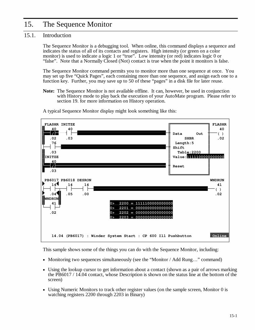
15-1
15. The Sequence Monitor
15.1. Introduction
The Sequence Monitor is a debugging tool. When online, this command displays a sequence and indicates the status of all of its contacts and registers. High intensity (or green on a color monitor) is used to indicate a logic 1 or “true”. Low intensity (or red) indicates logic 0 or “false”. Note that a Normally Closed (Not) contact is true when the point it monitors is false.
The Sequence Monitor command permits you to monitor more than one sequence at once. You may set up five “Quick Pages”, each containing more than one sequence, and assign each one to a function key. Further, you may save up to 50 of these “pages” in a disk file for later reuse.
Note: The Sequence Monitor is not available offline. It can, however, be used in conjunction with History mode to play back the execution of your AutoMate program. Please refer to section 19. for more information on History operation.
A typical Sequence Monitor display might look something like this:
FLASHR INITZE FLASHR 40 40 40
/ Data Out ( ) .02 .03 SHBR .02 76 Length:5
Shift .03 Table:2200 INITZE Value:1111100000000000 40
/ Reset .03 PB6017 PB6018 DESRON WNDRUN 14 14 14 41
( ) .04 .05 .00 .02 WNDRUN 41 0> 2200 = 1111100000000000
0> 2201 = 0000000000000000 .02 0> 2202 = 0000000000000000 0> 2203 = 0000000000000000 14.04 (PB6017) : Winder System Start : CP 600 Ill Pushbutton Online
This sample shows some of the things you can do with the Sequence Monitor, including:
• Monitoring two sequences simultaneously (see the “Monitor / Add Rung…” command)
• Using the lookup cursor to get information about a contact (shown as a pair of arrows marking the PB6017 / 14.04 contact, whose Description is shown on the status line at the bottom of the screen)
• Using Numeric Monitors to track other register values (on the sample screen, Monitor 0 is watching registers 2200 through 2203 in Binary)
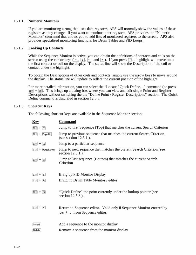
15-2
15.1.1. Numeric Monitors
If you are monitoring a rung that uses data registers, APS will normally show the values of these registers as they change. If you want to monitor other registers, APS provides the “Numeric Monitors” command that allows you to add lists of monitored registers to the screen. APS also provides specialized monitoring functions for Drum Tables and PID Loops.
15.1.2. Looking Up Contacts
While the Sequence Monitor is active, you can obtain the definitions of contacts and coils on the screen using the cursor keys (ß, Í, ®, and Â). If you press Â, a highlight will move onto the first contact or coil on the display. The status line will show the Description of the coil or contact under the highlight.
To obtain the Descriptions of other coils and contacts, simply use the arrow keys to move around the display. The status line will update to reflect the current position of the highlight.
For more detailed information, you can select the “Locate / Quick Define…” command (or press c + D). This brings up a dialog box where you can view and edit single Point and Register Descriptions without switching the the “Define Point / Register Descriptions” section. The Quick Define command is described in section 12.5.8.
15.1.3. Shortcut Keys
The following shortcut keys are available in the Sequence Monitor section:
Key Command
c + T Jump to first Sequence (Top) that matches the current Search Criterion
c + u Jump to previous sequence that matches the current Search Criterion (see section 12.5.1.).
c + G Jump to a particular sequence
c + v Jump to next sequence that matches the current Search Criterion (see section 12.5.1.).
c + B Jump to last sequence (Bottom) that matches the current Search Criterion
c + L Bring up PID Monitor Display
c + R Bring up Drum Table Monitor / editor
c + D “Quick Define” the point currently under the lookup pointer (see section 12.5.8.).
c + V Return to Sequence editor. Valid only if Sequence Monitor entered by c + V from Sequence editor.
i Add a sequence to the monitor display
d Remove a sequence from the monitor display
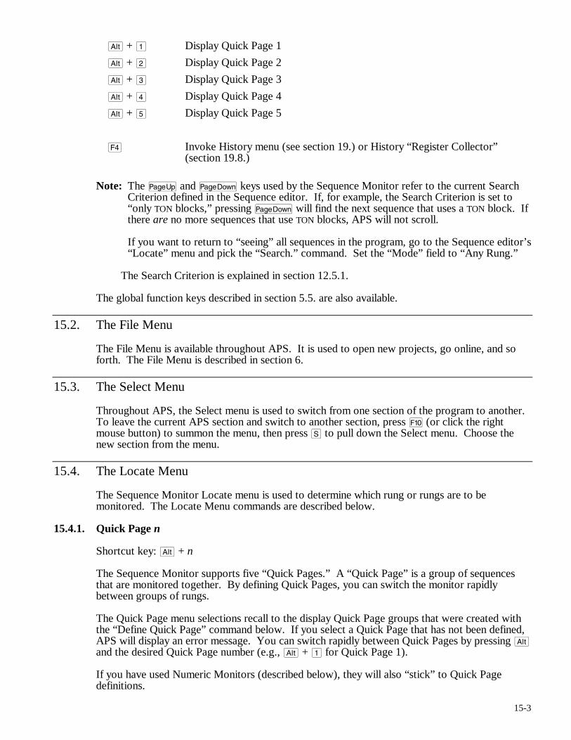
15-3
a + 1 Display Quick Page 1
a + 2 Display Quick Page 2
a + 3 Display Quick Page 3
a + 4 Display Quick Page 4
a + 5 Display Quick Page 5
$ Invoke History menu (see section 19.) or History “Register Collector” (section 19.8.)
Note: The u and v keys used by the Sequence Monitor refer to the current Search Criterion defined in the Sequence editor. If, for example, the Search Criterion is set to “only TON blocks,” pressing v will find the next sequence that uses a TON block. If there are no more sequences that use TON blocks, APS will not scroll.
If you want to return to “seeing” all sequences in the program, go to the Sequence editor’s “Locate” menu and pick the “Search.” command. Set the “Mode” field to “Any Rung.”
The Search Criterion is explained in section 12.5.1.
The global function keys described in section 5.5. are also available.
15.2. The File Menu
The File Menu is available throughout APS. It is used to open new projects, go online, and so forth. The File Menu is described in section 6.
15.3. The Select Menu
Throughout APS, the Select menu is used to switch from one section of the program to another. To leave the current APS section and switch to another section, press ) (or click the right mouse button) to summon the menu, then press S to pull down the Select menu. Choose the new section from the menu.
15.4. The Locate Menu
The Sequence Monitor Locate menu is used to determine which rung or rungs are to be monitored. The Locate Menu commands are described below.
15.4.1. Quick Page n
Shortcut key: a + n
The Sequence Monitor supports five “Quick Pages.” A “Quick Page” is a group of sequences that are monitored together. By defining Quick Pages, you can switch the monitor rapidly between groups of rungs.
The Quick Page menu selections recall to the display Quick Page groups that were created with the “Define Quick Page” command below. If you select a Quick Page that has not been defined, APS will display an error message. You can switch rapidly between Quick Pages by pressing a and the desired Quick Page number (e.g., a + 1 for Quick Page 1).
If you have used Numeric Monitors (described below), they will also “stick” to Quick Page definitions.
15-4
Note: You must use the number keys above the “typewriter” keys, not the keypad number keys, to recall Quick Pages.
15.4.2. Define Quick Page…
The “Locate / Def Quick Page…” command “attaches” a group of sequences to a Quick Page. When you select this command, APS will ask for the quick page number; press 1, 2, 3, 4, or 5. Pressing q will cancel the command. New definitions automatically replace any previous definitions.
For example, suppose that you had created a Sequence Monitor display that included rungs 12.01, 3.03, and 6.12. If you used “Locate / Def Quick Page…” to attach these rungs to Quick Page 1, you could bring them up for monitoring again at any time by pressing a + 1 or by selecting “Locate / Quick Page 1” from the menu. Quick Pages also store any Numeric Monitor definitions on the monitor display.
Quick Page definitions can be saved from session to session using the “Monitor / Load Page…” and “Monitor / Save Page…” commands described below. If you do not save the Quick Page definitions, they will be lost when you leave APS.
15.4.3. Top
Shortcut key: c + T
The Top command brings up the first sequence in the program that matches the current Search Criterion (see section 12.5.1.).
15.4.4. Previous
Shortcut key: u
The Previous command brings up the previous sequence in the program that matches the current Search Criterion (see section 12.5.1.).
15.4.5. Goto…
Shortcut key: c + G
Use the Goto command to bring up a specific sequence for monitoring. Enter the target rung’s output coil address, Name, or Line Number and press r.
15.4.6. Next
Shortcut key: v
The Next command brings up the next sequence in the program that matches the current Search Criterion (see section 12.5.1.).
15.4.7. Bottom
Shortcut key: c + B
The Bottom command brings up the last sequence in the program that matches the current Search Criterion (see section 12.5.1.).
15-5
15.4.8. Quick Define
Shortcut key: c + D
Brings up the Quick Define dialog box for the currently-highlighted point. If no point is highlighted, APS will prompt you for the address to define. The Quick Define command is described in detail in section 12.5.8.
15.5. The Monitor Menu
This menu adds and removes rungs from the display, saves and retrieves Quick Page definitions, and pulls up special monitoring screens for PID loops and Drum tables.
15.5.1. Add Sequence…
Shortcut key: i
The Add Sequence command allows you to add a sequence to those already displayed, as long as there is room on the screen for the new sequence. New sequences are always added below those already on the display.
When you select the “Monitor / Add sequence…” command, APS will display a dialog box asking for the new sequence’s output coil address. Type the address and press r to add the sequence. APS will display a message and cancel the operation if the new sequence is too large to fit on the screen.
15.5.2. Remove Sequence…
Shortcut key: d
The Remove Sequence command removes a sequence from the current Sequence Monitor display. APS will prompt for the output coil address of the sequence to remove; type the address and press r to remove the rung or press q to cancel the command.
Note: APS will not let you Remove the last sequence on the display.
15.5.3. Load Page
If you have groups of Quick Pages that you monitor frequently, you can use the “Monitor / Load Page…” and “Monitor / Save Page…” to store them to disk for later retrieval. The “Monitor / Load Page…” command retrieves a group of Quick Pages stored with the “Monitor / Save Page…” command.
The procedure used for retrieving stored Quick Pages is the same as that used for Register Monitor pages. Please see section 16.4.5. for a description of this procedure.
15.5.4. Save Page
The “Monitor / Save Page…” command stores the current Quick Page definitions to a disk file so that they can be retrieved later with the “Monitor / Load Page…” command.
The procedure used for storing Quick Pages is the same as that used for Register Monitor pages. Please see section 16.4.6. for a description of this procedure.
15.5.5. Add Numeric Monitor…
APS provides a way to monitor up to 10 groups of registers while you monitor sequences. This facility is called the Numeric Monitor system.
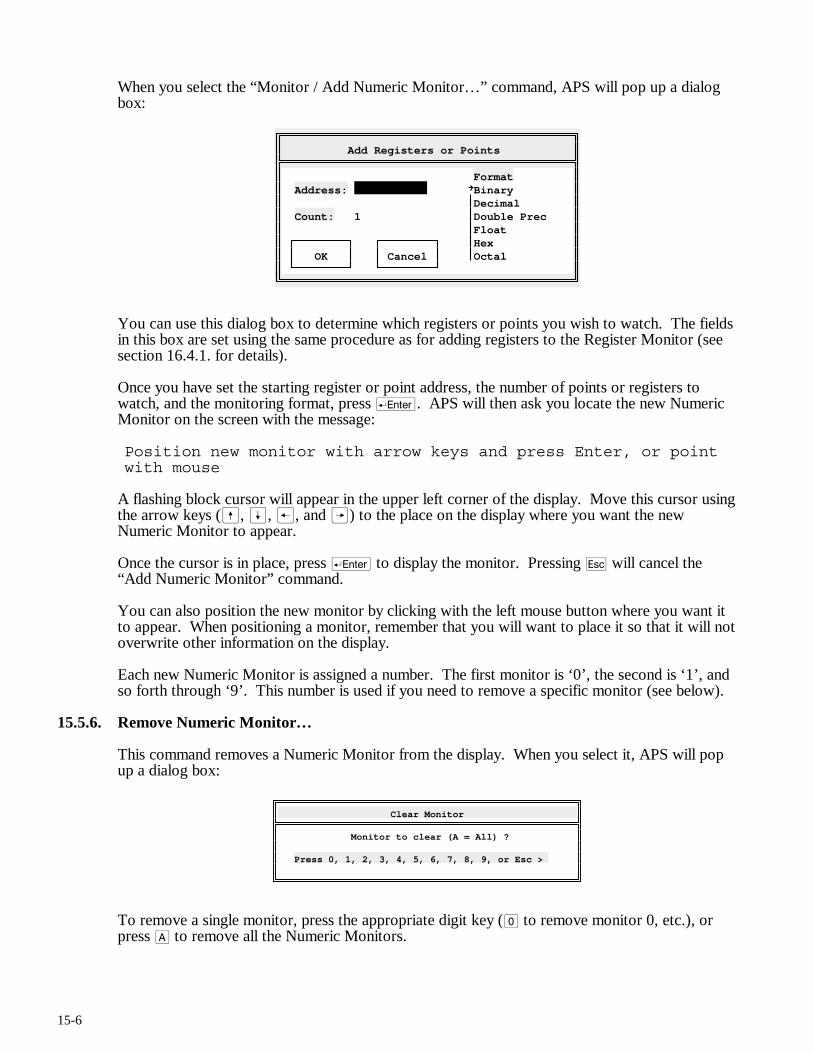
15-6
When you select the “Monitor / Add Numeric Monitor…” command, APS will pop up a dialog box:
Add Registers or Points
Format Address: Binary Decimal Count: 1 Double Prec Float Hex OK Cancel Octal
You can use this dialog box to determine which registers or points you wish to watch. The fields in this box are set using the same procedure as for adding registers to the Register Monitor (see section 16.4.1. for details).
Once you have set the starting register or point address, the number of points or registers to watch, and the monitoring format, press r. APS will then ask you locate the new Numeric Monitor on the screen with the message:
Position new monitor with arrow keys and press Enter, or point with mouse
A flashing block cursor will appear in the upper left corner of the display. Move this cursor using the arrow keys (ß, Í, ®, and Â) to the place on the display where you want the new Numeric Monitor to appear.
Once the cursor is in place, press r to display the monitor. Pressing q will cancel the “Add Numeric Monitor” command.
You can also position the new monitor by clicking with the left mouse button where you want it to appear. When positioning a monitor, remember that you will want to place it so that it will not overwrite other information on the display.
Each new Numeric Monitor is assigned a number. The first monitor is ‘0’, the second is ‘1’, and so forth through ‘9’. This number is used if you need to remove a specific monitor (see below).
15.5.6. Remove Numeric Monitor…
This command removes a Numeric Monitor from the display. When you select it, APS will pop up a dialog box:
Clear Monitor
Monitor to clear (A = All) ? Press 0, 1, 2, 3, 4, 5, 6, 7, 8, 9, or Esc >
To remove a single monitor, press the appropriate digit key (0 to remove monitor 0, etc.), or press A to remove all the Numeric Monitors.
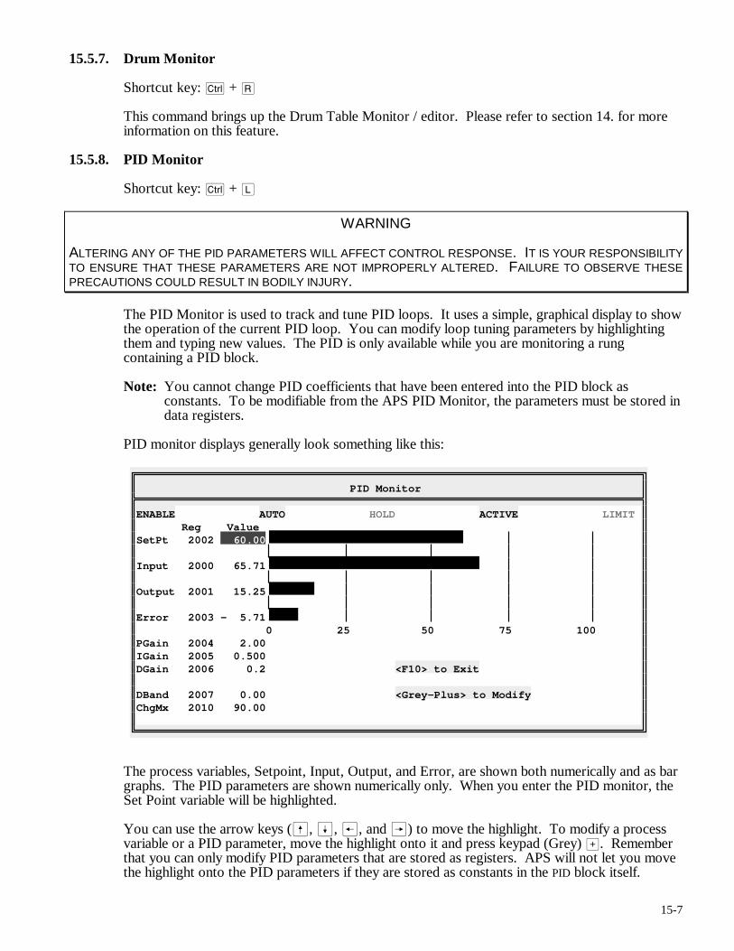
15-7
15.5.7. Drum Monitor
Shortcut key: c + R
This command brings up the Drum Table Monitor / editor. Please refer to section 14. for more information on this feature.
15.5.8. PID Monitor
Shortcut key: c + L
WARNING
ALTERING ANY OF THE PID PARAMETERS WILL AFFECT CONTROL RESPONSE. IT IS YOUR RESPONSIBILITY TO ENSURE THAT THESE PARAMETERS ARE NOT IMPROPERLY ALTERED. FAILURE TO OBSERVE THESE PRECAUTIONS COULD RESULT IN BODILY INJURY.
The PID Monitor is used to track and tune PID loops. It uses a simple, graphical display to show the operation of the current PID loop. You can modify loop tuning parameters by highlighting them and typing new values. The PID is only available while you are monitoring a rung containing a PID block.
Note: You cannot change PID coefficients that have been entered into the PID block as constants. To be modifiable from the APS PID Monitor, the parameters must be stored in data registers.
PID monitor displays generally look something like this:
PID Monitor
ENABLE AUTO HOLD ACTIVE LIMIT Reg Value SetPt 2002 60.00 Input 2000 65.71 Output 2001 15.25 Error 2003 - 5.71 0 25 50 75 100 PGain 2004 2.00 IGain 2005 0.500 DGain 2006 0.2 <F10> to Exit DBand 2007 0.00 <Grey-Plus> to Modify ChgMx 2010 90.00
The process variables, Setpoint, Input, Output, and Error, are shown both numerically and as bar graphs. The PID parameters are shown numerically only. When you enter the PID monitor, the Set Point variable will be highlighted.
You can use the arrow keys (ß, Í, ®, and Â) to move the highlight. To modify a process variable or a PID parameter, move the highlight onto it and press keypad (Grey) >. Remember that you can only modify PID parameters that are stored as registers. APS will not let you move the highlight onto the PID parameters if they are stored as constants in the PID block itself.
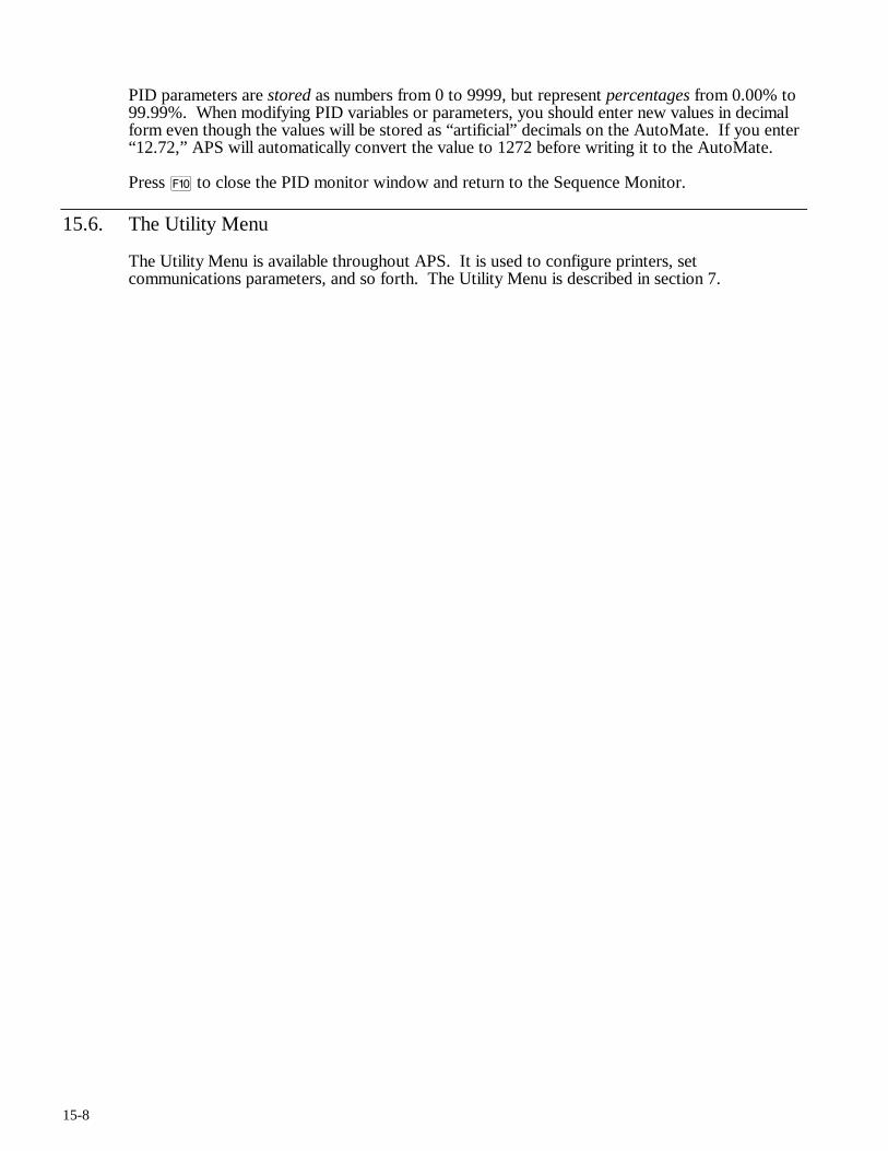
15-8
PID parameters are stored as numbers from 0 to 9999, but represent percentages from 0.00% to 99.99%. When modifying PID variables or parameters, you should enter new values in decimal form even though the values will be stored as “artificial” decimals on the AutoMate. If you enter “12.72,” APS will automatically convert the value to 1272 before writing it to the AutoMate.
Press ) to close the PID monitor window and return to the Sequence Monitor.
15.6. The Utility Menu
The Utility Menu is available throughout APS. It is used to configure printers, set communications parameters, and so forth. The Utility Menu is described in section 7.
16-1
16. The Register Monitor
16.1. Introduction
DANGER
ONLY QUALIFIED ELECTRICAL PERSONNEL FAMILIAR WITH THE CONSTRUCTION AND OPERATION OF THIS EQUIPMENT AND THE HAZARDS INVOLVED SHOULD INSTALL, ADJUST, OPERATE, AND/OR SERVICE IT. READ AND UNDERSTAND THE APPLICABLE MANUALS IN THEIR ENTIRETY BEFORE PROCEEDING. FAILURE TO OBSERVE THESE PRECAUTIONS COULD RESULT IN SEVERE BODILY INJURY OR LOSS OF LIFE.
WARNING
DURING SINGLE SCAN EXECUTION, ALL APPLICATION LOGIC IS SOLVED AND THE CONFIGURED DIGITAL I/O ARE UPDATED. NEITHER THE I/O NOR ANY INTERNAL REGISTERS OR POINTS ARE RESET AT THE COMPLETION OF THE SCAN. THE USER MUST RESET THE I/O. FAILURE TO OBSERVE THESE PRECAUTIONS COULD RESULT IN BODILY INJURY.
The Register Monitor is used to track values of up to 64 registers or points, modify registers, and force Digital I/O points. It can be used both online and offline.
When offline, the Register Monitor displays and modifies the values stored in the data register space. This can be useful for setting Preset values and other constants. Note that these values will only be transferred to the AutoMate Processor during a Download operation.
In the online mode, the Register Monitor shows actual register values. The online mode also permits debugging operations like forcing and unforcing I/O points. Modifying a register value online writes the new value both to the computer’s data register area and to the Processor.
Register Monitor pages can be saved and loaded from disk to make recreating commonly used tables of registers easy. The Register Monitor also provides a String Monitor for editing and monitoring ASCII strings.
The Register Monitor can also be used in History mode, in which case it “plays back” register values from a log file. Please refer to section 19. for more information on History mode.
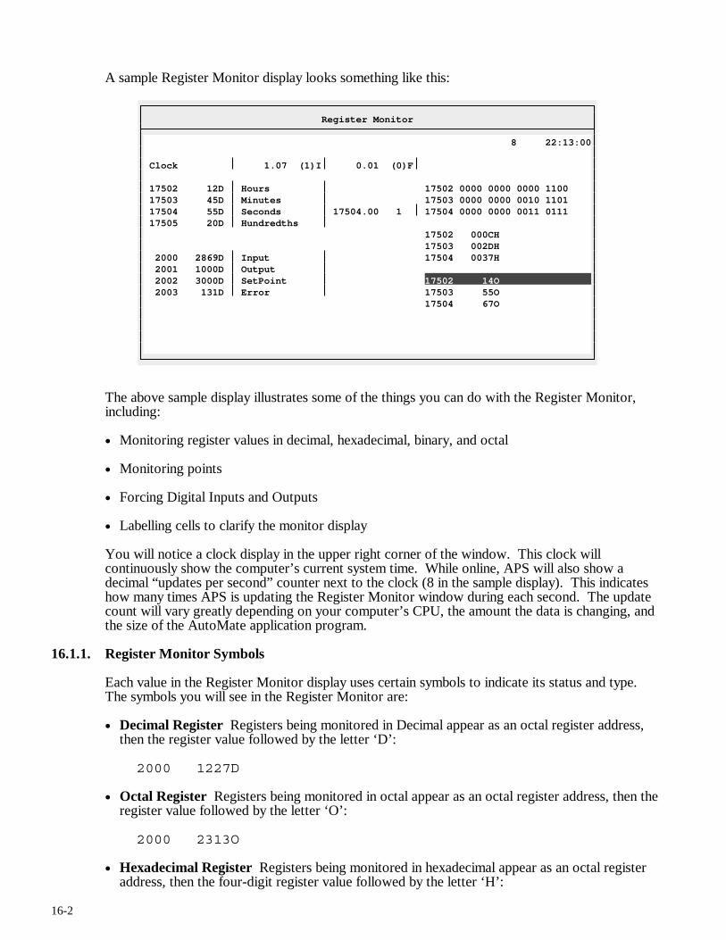
16-2
A sample Register Monitor display looks something like this:
Register Monitor
8 22:13:00 Clock 1.07 (1)I 0.01 (0)F 17502 12D Hours 17502 0000 0000 0000 1100 17503 45D Minutes 17503 0000 0000 0010 1101 17504 55D Seconds 17504.00 1 17504 0000 0000 0011 0111 17505 20D Hundredths 17502 000CH 17503 002DH 2000 2869D Input 17504 0037H 2001 1000D Output 2002 3000D SetPoint 17502 14O 2003 131D Error 17503 55O 17504 67O
The above sample display illustrates some of the things you can do with the Register Monitor, including:
• Monitoring register values in decimal, hexadecimal, binary, and octal
• Monitoring points
• Forcing Digital Inputs and Outputs
• Labelling cells to clarify the monitor display
You will notice a clock display in the upper right corner of the window. This clock will continuously show the computer’s current system time. While online, APS will also show a decimal “updates per second” counter next to the clock (8 in the sample display). This indicates how many times APS is updating the Register Monitor window during each second. The update count will vary greatly depending on your computer’s CPU, the amount the data is changing, and the size of the AutoMate application program.
16.1.1. Register Monitor Symbols
Each value in the Register Monitor display uses certain symbols to indicate its status and type. The symbols you will see in the Register Monitor are:
• Decimal Register Registers being monitored in Decimal appear as an octal register address, then the register value followed by the letter ‘D’:
2000 1227D
• Octal Register Registers being monitored in octal appear as an octal register address, then the register value followed by the letter ‘O’:
2000 2313O
• Hexadecimal Register Registers being monitored in hexadecimal appear as an octal register address, then the four-digit register value followed by the letter ‘H’:
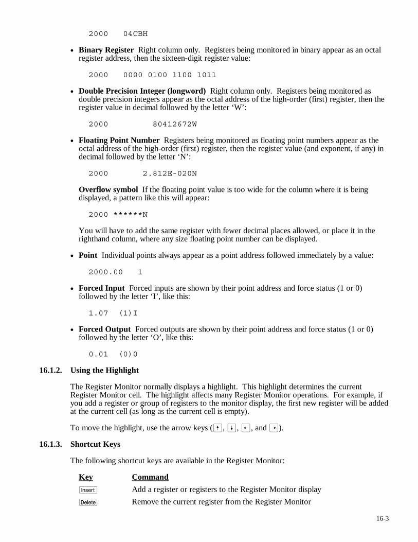
16-3
2000 04CBH
• Binary Register Right column only. Registers being monitored in binary appear as an octal register address, then the sixteen-digit register value:
2000 0000 0100 1100 1011
• Double Precision Integer (longword) Right column only. Registers being monitored as double precision integers appear as the octal address of the high-order (first) register, then the register value in decimal followed by the letter ‘W’:
2000 80412672W
• Floating Point Number Registers being monitored as floating point numbers appear as the octal address of the high-order (first) register, then the register value (and exponent, if any) in decimal followed by the letter ‘N’:
2000 2.812E-020N
Overflow symbol If the floating point value is too wide for the column where it is being displayed, a pattern like this will appear:
2000 ******N
You will have to add the same register with fewer decimal places allowed, or place it in the righthand column, where any size floating point number can be displayed.
• Point Individual points always appear as a point address followed immediately by a value:
2000.00 1
• Forced Input Forced inputs are shown by their point address and force status (1 or 0) followed by the letter ‘I’, like this:
1.07 (1)I
• Forced Output Forced outputs are shown by their point address and force status (1 or 0) followed by the letter ‘O’, like this:
0.01 (0)0
16.1.2. Using the Highlight
The Register Monitor normally displays a highlight. This highlight determines the current Register Monitor cell. The highlight affects many Register Monitor operations. For example, if you add a register or group of registers to the monitor display, the first new register will be added at the current cell (as long as the current cell is empty).
To move the highlight, use the arrow keys (ß, Í, ®, and Â).
16.1.3. Shortcut Keys
The following shortcut keys are available in the Register Monitor:
Key Command
i Add a register or registers to the Register Monitor display
d Remove the current register from the Register Monitor
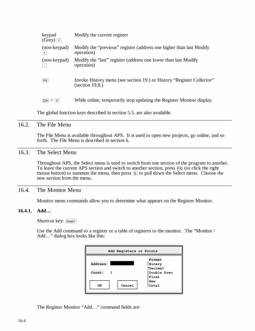
16-4
keypad (Grey) >
Modify the current register
(non-keypad) >
Modify the “previous” register (address one higher than last Modify operation)
(non-keypad) -
Modify the “last” register (address one lower than last Modify operation)
$ Invoke History menu (see section 19.) or History “Register Collector” (section 19.8.)
c + V While online, temporarily stop updating the Register Monitor display.
The global function keys described in section 5.5. are also available.
16.2. The File Menu
The File Menu is available throughout APS. It is used to open new projects, go online, and so forth. The File Menu is described in section 6.
16.3. The Select Menu
Throughout APS, the Select menu is used to switch from one section of the program to another. To leave the current APS section and switch to another section, press ) (or click the right mouse button) to summon the menu, then press S to pull down the Select menu. Choose the new section from the menu.
16.4. The Monitor Menu
Monitor menu commands allow you to determine what appears on the Register Monitor.
16.4.1. Add…
Shortcut key: i
Use the Add command to a register or a table of registers to the monitor. The “Monitor / Add…” dialog box looks like this:
Add Registers or Points
Format Address: Binary Decimal Count: 1 Double Prec Float Hex OK Cancel Octal
The Register Monitor “Add…” command fields are:
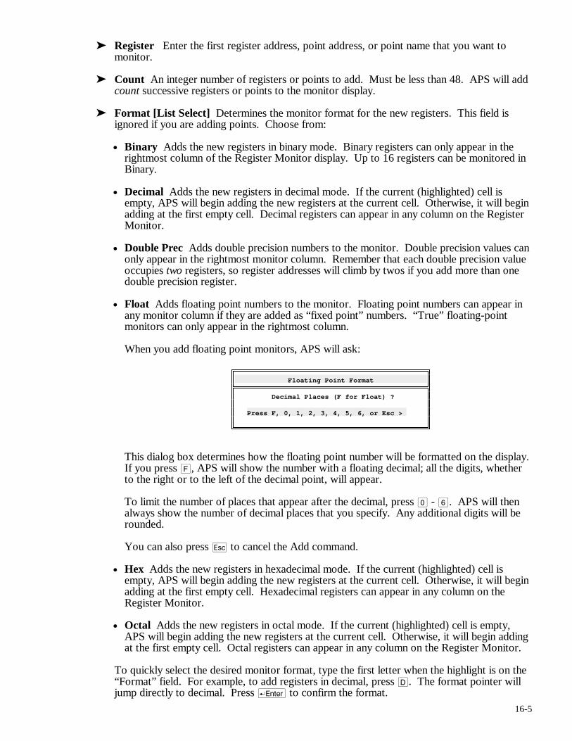
16-5
➤ Register Enter the first register address, point address, or point name that you want to monitor.
➤ Count An integer number of registers or points to add. Must be less than 48. APS will add count successive registers or points to the monitor display.
➤ Format [List Select] Determines the monitor format for the new registers. This field is ignored if you are adding points. Choose from:
• Binary Adds the new registers in binary mode. Binary registers can only appear in the rightmost column of the Register Monitor display. Up to 16 registers can be monitored in Binary.
• Decimal Adds the new registers in decimal mode. If the current (highlighted) cell is empty, APS will begin adding the new registers at the current cell. Otherwise, it will begin adding at the first empty cell. Decimal registers can appear in any column on the Register Monitor.
• Double Prec Adds double precision numbers to the monitor. Double precision values can only appear in the rightmost monitor column. Remember that each double precision value occupies two registers, so register addresses will climb by twos if you add more than one double precision register.
• Float Adds floating point numbers to the monitor. Floating point numbers can appear in any monitor column if they are added as “fixed point” numbers. “True” floating-point monitors can only appear in the rightmost column.
When you add floating point monitors, APS will ask:
Floating Point Format
Decimal Places (F for Float) ? Press F, 0, 1, 2, 3, 4, 5, 6, or Esc >
This dialog box determines how the floating point number will be formatted on the display. If you press F, APS will show the number with a floating decimal; all the digits, whether to the right or to the left of the decimal point, will appear.
To limit the number of places that appear after the decimal, press 0 - 6. APS will then always show the number of decimal places that you specify. Any additional digits will be rounded.
You can also press q to cancel the Add command.
• Hex Adds the new registers in hexadecimal mode. If the current (highlighted) cell is empty, APS will begin adding the new registers at the current cell. Otherwise, it will begin adding at the first empty cell. Hexadecimal registers can appear in any column on the Register Monitor.
• Octal Adds the new registers in octal mode. If the current (highlighted) cell is empty, APS will begin adding the new registers at the current cell. Otherwise, it will begin adding at the first empty cell. Octal registers can appear in any column on the Register Monitor.
To quickly select the desired monitor format, type the first letter when the highlight is on the “Format” field. For example, to add registers in decimal, press D. The format pointer will jump directly to decimal. Press r to confirm the format.
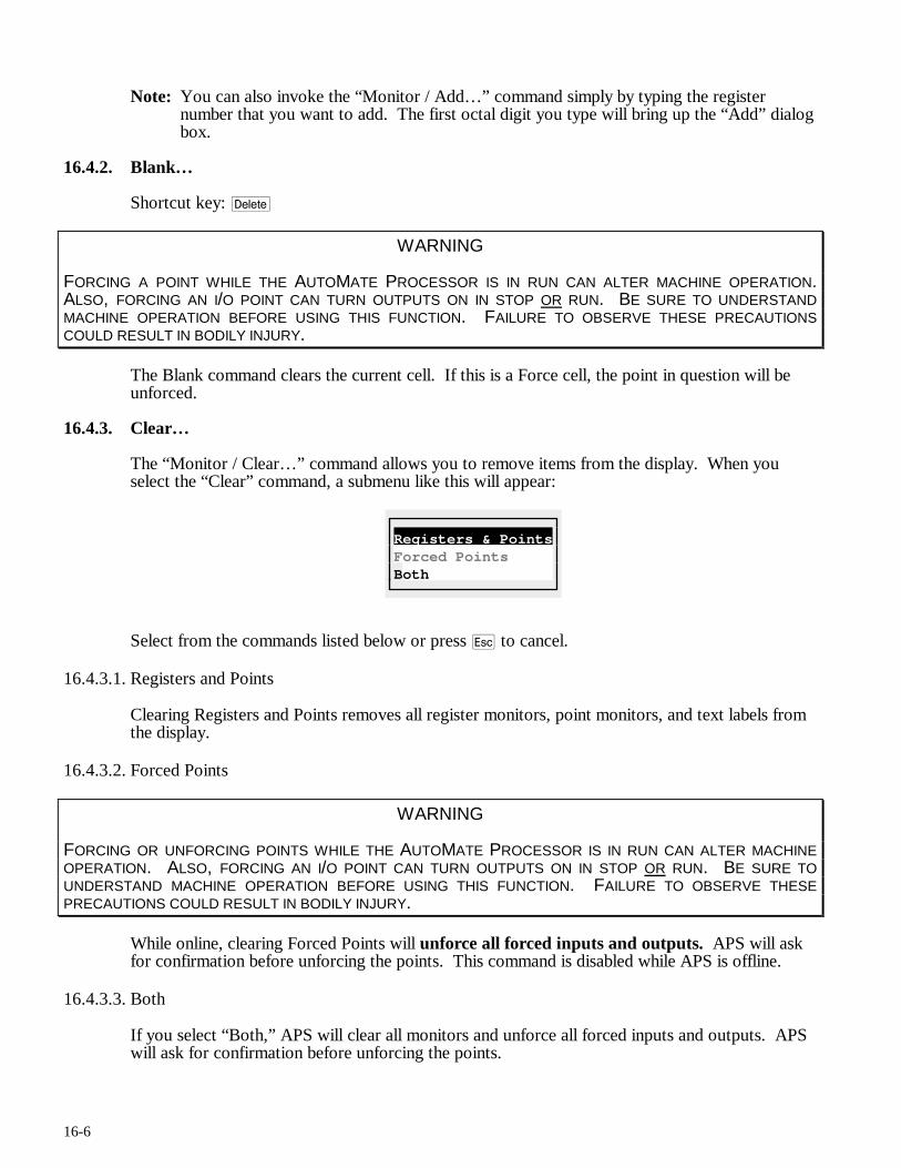
16-6
Note: You can also invoke the “Monitor / Add…” command simply by typing the register number that you want to add. The first octal digit you type will bring up the “Add” dialog box.
16.4.2. Blank…
Shortcut key: d
WARNING
FORCING A POINT WHILE THE AUTOMATE PROCESSOR IS IN RUN CAN ALTER MACHINE OPERATION. ALSO, FORCING AN I/O POINT CAN TURN OUTPUTS ON IN STOP OR RUN. BE SURE TO UNDERSTAND MACHINE OPERATION BEFORE USING THIS FUNCTION. FAILURE TO OBSERVE THESE PRECAUTIONS COULD RESULT IN BODILY INJURY.
The Blank command clears the current cell. If this is a Force cell, the point in question will be unforced.
16.4.3. Clear…
The “Monitor / Clear…” command allows you to remove items from the display. When you select the “Clear” command, a submenu like this will appear:
Registers & PointsForced Points Both
Select from the commands listed below or press q to cancel.
16.4.3.1. Registers and Points
Clearing Registers and Points removes all register monitors, point monitors, and text labels from the display.
16.4.3.2. Forced Points
WARNING
FORCING OR UNFORCING POINTS WHILE THE AUTOMATE PROCESSOR IS IN RUN CAN ALTER MACHINE OPERATION. ALSO, FORCING AN I/O POINT CAN TURN OUTPUTS ON IN STOP OR RUN. BE SURE TO UNDERSTAND MACHINE OPERATION BEFORE USING THIS FUNCTION. FAILURE TO OBSERVE THESE PRECAUTIONS COULD RESULT IN BODILY INJURY.
While online, clearing Forced Points will unforce all forced inputs and outputs. APS will ask for confirmation before unforcing the points. This command is disabled while APS is offline.
16.4.3.3. Both
If you select “Both,” APS will clear all monitors and unforce all forced inputs and outputs. APS will ask for confirmation before unforcing the points.
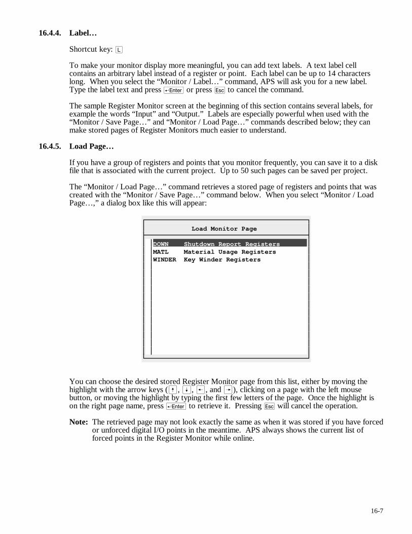
16-7
16.4.4. Label…
Shortcut key: L
To make your monitor display more meaningful, you can add text labels. A text label cell contains an arbitrary label instead of a register or point. Each label can be up to 14 characters long. When you select the “Monitor / Label…” command, APS will ask you for a new label. Type the label text and press r or press q to cancel the command.
The sample Register Monitor screen at the beginning of this section contains several labels, for example the words “Input” and “Output.” Labels are especially powerful when used with the “Monitor / Save Page…” and “Monitor / Load Page…” commands described below; they can make stored pages of Register Monitors much easier to understand.
16.4.5. Load Page…
If you have a group of registers and points that you monitor frequently, you can save it to a disk file that is associated with the current project. Up to 50 such pages can be saved per project.
The “Monitor / Load Page…” command retrieves a stored page of registers and points that was created with the “Monitor / Save Page…” command below. When you select “Monitor / Load Page…,” a dialog box like this will appear:
Load Monitor Page
DOWN Shutdown Report Registers MATL Material Usage Registers WINDER Key Winder Registers
You can choose the desired stored Register Monitor page from this list, either by moving the highlight with the arrow keys (ß, Í, ®, and Â), clicking on a page with the left mouse button, or moving the highlight by typing the first few letters of the page. Once the highlight is on the right page name, press r to retrieve it. Pressing q will cancel the operation.
Note: The retrieved page may not look exactly the same as when it was stored if you have forced or unforced digital I/O points in the meantime. APS always shows the current list of forced points in the Register Monitor while online.
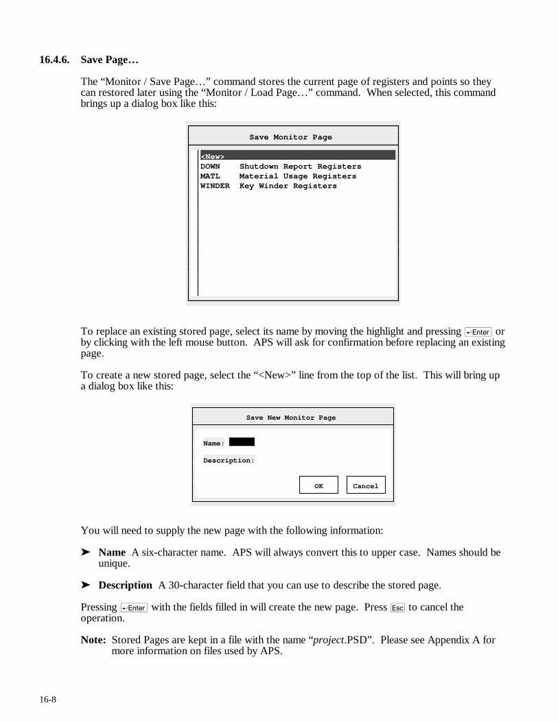
16-8
16.4.6. Save Page…
The “Monitor / Save Page…” command stores the current page of registers and points so they can restored later using the “Monitor / Load Page…” command. When selected, this command brings up a dialog box like this:
Save Monitor Page
<New> DOWN Shutdown Report Registers MATL Material Usage Registers WINDER Key Winder Registers
To replace an existing stored page, select its name by moving the highlight and pressing r or by clicking with the left mouse button. APS will ask for confirmation before replacing an existing page.
To create a new stored page, select the “<New>” line from the top of the list. This will bring up a dialog box like this:
Save New Monitor Page
Name: Description: OK Cancel
You will need to supply the new page with the following information:
➤ Name A six-character name. APS will always convert this to upper case. Names should be unique.
➤ Description A 30-character field that you can use to describe the stored page.
Pressing r with the fields filled in will create the new page. Press q to cancel the operation.
Note: Stored Pages are kept in a file with the name “project.PSD”. Please see Appendix A for more information on files used by APS.
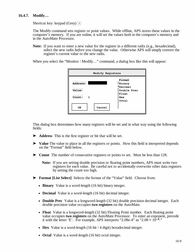
16-9
16.4.7. Modify…
Shortcut key: keypad (Grey) >
The Modify command sets register or point values. While offline, APS stores these values in the computer’s memory. If you are online, it will set the values both in the computer’s memory and in the AutoMate Processor.
Note: If you want to enter a new value for the register in a different radix (e.g., hexadecimal), select the new radix before you change the value. Otherwise APS will simply convert the register’s current value to the new radix.
When you select the “Monitor / Modify…” command, a dialog box like this will appear:
Modify Registers
Format Address: Binary Decimal Value: Double Prec Float Count: 1 Hex Octal OK Cancel
This dialog box determines how many registers will be set and in what way using the following fields:
➤ Address This is the first register or bit that will be set.
➤ Value The value to place in all the registers or points. How this field is interpreted depends on the “Format” field below.
➤ Count The number of consecutive registers or points to set. Must be less than 128.
Note: If you are setting double precision or floating point numbers, APS must write two registers for each value. Be careful not to accidentally overwrite other data registers by setting the count too high.
➤ Format [List Select] Selects the format of the “Value” field. Choose from:
• Binary Value is a word-length (16 bit) binary integer.
• Decimal Value is a word-length (16 bit) decimal integer.
• Double Prec Value is a longword-length (32 bit) double precision decimal integer. Each double precision value occupies two registers on the AutoMate.
• Float Value is a longword-length (32 bit) Floating Point number. Each floating point value occupies two registers on the AutoMate Processor. To enter an exponent, precede it with the letter ‘E’. For example, APS interprets “2.08e-4” as “2.08 × 10⁻⁴.”
• Hex Value is a word-length (16 bit / 4 digit) hexadecimal integer.
• Octal Value is a word-length (16 bit) octal integer.
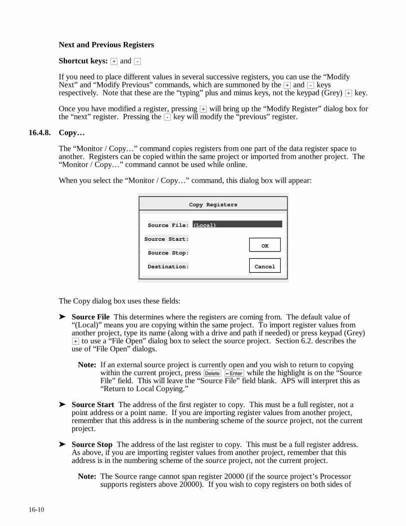
16-10
Next and Previous Registers
Shortcut keys: > and -
If you need to place different values in several successive registers, you can use the “Modify Next” and “Modify Previous” commands, which are summoned by the > and - keys respectively. Note that these are the “typing” plus and minus keys, not the keypad (Grey) > key.
Once you have modified a register, pressing > will bring up the “Modify Register” dialog box for the “next” register. Pressing the - key will modify the “previous” register.
16.4.8. Copy…
The “Monitor / Copy…” command copies registers from one part of the data register space to another. Registers can be copied within the same project or imported from another project. The “Monitor / Copy…” command cannot be used while online.
When you select the “Monitor / Copy…” command, this dialog box will appear:
Copy Registers
Source File: (Local) Source Start: OK Source Stop: Destination: Cancel
The Copy dialog box uses these fields:
➤ Source File This determines where the registers are coming from. The default value of “(Local)” means you are copying within the same project. To import register values from another project, type its name (along with a drive and path if needed) or press keypad (Grey) > to use a “File Open” dialog box to select the source project. Section 6.2. describes the use of “File Open” dialogs.
Note: If an external source project is currently open and you wish to return to copying within the current project, press d r while the highlight is on the “Source File” field. This will leave the “Source File” field blank. APS will interpret this as “Return to Local Copying.”
➤ Source Start The address of the first register to copy. This must be a full register, not a point address or a point name. If you are importing register values from another project, remember that this address is in the numbering scheme of the source project, not the current project.
➤ Source Stop The address of the last register to copy. This must be a full register address. As above, if you are importing register values from another project, remember that this address is in the numbering scheme of the source project, not the current project.
Note: The Source range cannot span register 20000 (if the source project’s Processor supports registers above 20000). If you wish to copy registers on both sides of
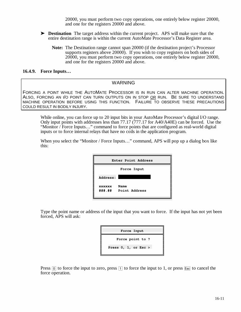
16-11
20000, you must perform two copy operations, one entirely below register 20000, and one for the registers 20000 and above.
➤ Destination The target address within the current project. APS will make sure that the entire destination range is within the current AutoMate Processor’s Data Register area.
Note: The Destination range cannot span 20000 (if the destination project’s Processor supports registers above 20000). If you wish to copy registers on both sides of 20000, you must perform two copy operations, one entirely below register 20000, and one for the registers 20000 and above.
16.4.9. Force Inputs…
WARNING
FORCING A POINT WHILE THE AUTOMATE PROCESSOR IS IN RUN CAN ALTER MACHINE OPERATION. ALSO, FORCING AN I/O POINT CAN TURN OUTPUTS ON IN STOP OR RUN. BE SURE TO UNDERSTAND MACHINE OPERATION BEFORE USING THIS FUNCTION. FAILURE TO OBSERVE THESE PRECAUTIONS COULD RESULT IN BODILY INJURY.
While online, you can force up to 20 input bits in your AutoMate Processor’s digital I/O range. Only input points with addresses less than 77.17 (777.17 for A40/A40E) can be forced. Use the “Monitor / Force Inputs…” command to force points that are configured as real-world digital inputs or to force internal relays that have no coils in the application program.
When you select the “Monitor / Force Inputs…” command, APS will pop up a dialog box like this:
Enter Point Address
Force Input Address: xxxxxx Name ###.## Point Address
Type the point name or address of the input that you want to force. If the input has not yet been forced, APS will ask:
Force Input
Force point to ? Press 0, 1, or Esc >
Press 0 to force the input to zero, press 1 to force the input to 1, or press q to cancel the force operation.
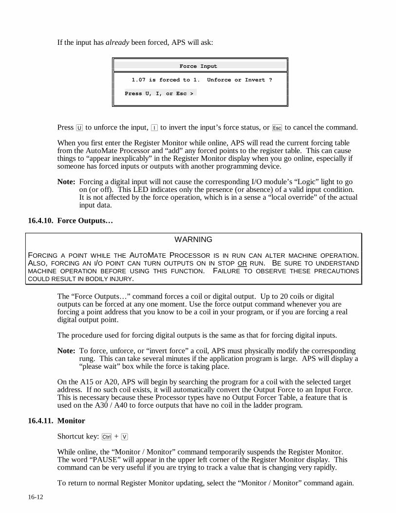
16-12
If the input has already been forced, APS will ask:
Force Input
1.07 is forced to 1. Unforce or Invert ? Press U, I, or Esc >
Press U to unforce the input, I to invert the input’s force status, or q to cancel the command.
When you first enter the Register Monitor while online, APS will read the current forcing table from the AutoMate Processor and “add” any forced points to the register table. This can cause things to “appear inexplicably” in the Register Monitor display when you go online, especially if someone has forced inputs or outputs with another programming device.
Note: Forcing a digital input will not cause the corresponding I/O module’s “Logic” light to go on (or off). This LED indicates only the presence (or absence) of a valid input condition. It is not affected by the force operation, which is in a sense a “local override” of the actual input data.
16.4.10. Force Outputs…
WARNING
FORCING A POINT WHILE THE AUTOMATE PROCESSOR IS IN RUN CAN ALTER MACHINE OPERATION. ALSO, FORCING AN I/O POINT CAN TURN OUTPUTS ON IN STOP OR RUN. BE SURE TO UNDERSTAND MACHINE OPERATION BEFORE USING THIS FUNCTION. FAILURE TO OBSERVE THESE PRECAUTIONS COULD RESULT IN BODILY INJURY.
The “Force Outputs…” command forces a coil or digital output. Up to 20 coils or digital outputs can be forced at any one moment. Use the force output command whenever you are forcing a point address that you know to be a coil in your program, or if you are forcing a real digital output point.
The procedure used for forcing digital outputs is the same as that for forcing digital inputs.
Note: To force, unforce, or “invert force” a coil, APS must physically modify the corresponding rung. This can take several minutes if the application program is large. APS will display a “please wait” box while the force is taking place.
On the A15 or A20, APS will begin by searching the program for a coil with the selected target address. If no such coil exists, it will automatically convert the Output Force to an Input Force. This is necessary because these Processor types have no Output Forcer Table, a feature that is used on the A30 / A40 to force outputs that have no coil in the ladder program.
16.4.11. Monitor
Shortcut key: c + V
While online, the “Monitor / Monitor” command temporarily suspends the Register Monitor. The word “PAUSE” will appear in the upper left corner of the Register Monitor display. This command can be very useful if you are trying to track a value that is changing very rapidly.
To return to normal Register Monitor updating, select the “Monitor / Monitor” command again.
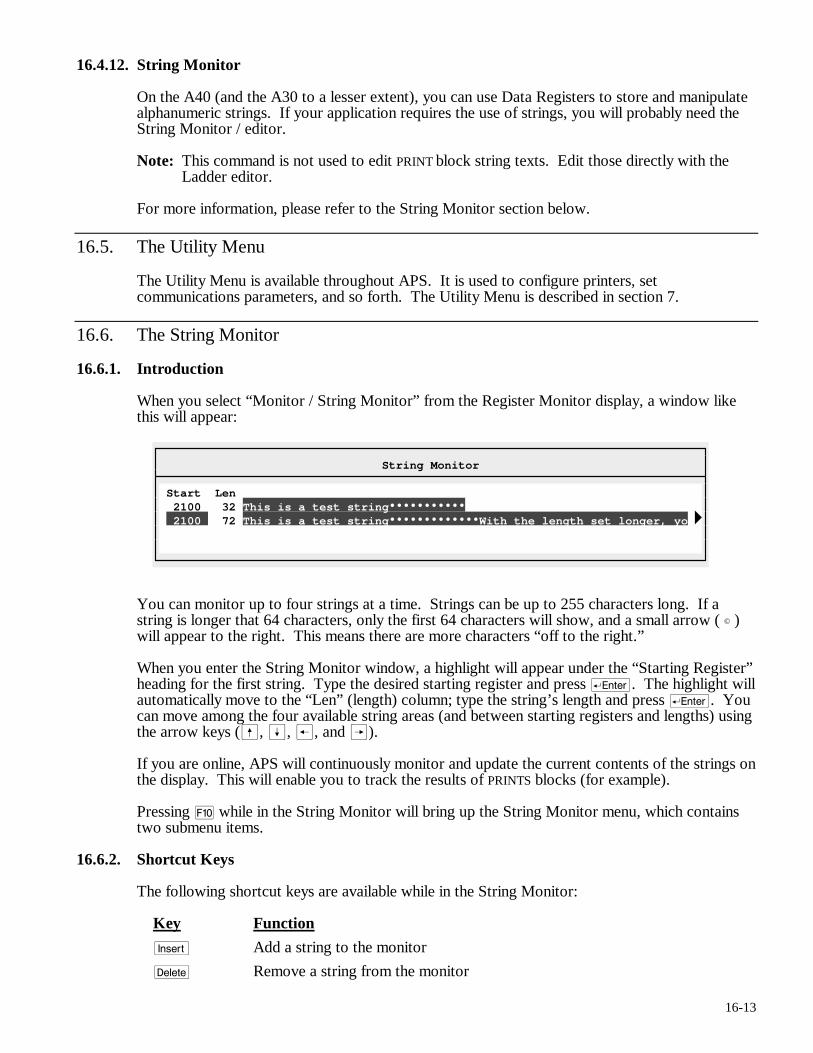
16-13
16.4.12. String Monitor
On the A40 (and the A30 to a lesser extent), you can use Data Registers to store and manipulate alphanumeric strings. If your application requires the use of strings, you will probably need the String Monitor / editor.
Note: This command is not used to edit PRINT block string texts. Edit those directly with the Ladder editor.
For more information, please refer to the String Monitor section below.
16.5. The Utility Menu
The Utility Menu is available throughout APS. It is used to configure printers, set communications parameters, and so forth. The Utility Menu is described in section 7.
16.6. The String Monitor
16.6.1. Introduction
When you select “Monitor / String Monitor” from the Register Monitor display, a window like this will appear:
String Monitor
Start Len 2100 32 This is a test string 2100 72 This is a test string With the length set longer, yo
You can monitor up to four strings at a time. Strings can be up to 255 characters long. If a string is longer that 64 characters, only the first 64 characters will show, and a small arrow ( © ) will appear to the right. This means there are more characters “off to the right.”
When you enter the String Monitor window, a highlight will appear under the “Starting Register” heading for the first string. Type the desired starting register and press r. The highlight will automatically move to the “Len” (length) column; type the string’s length and press r. You can move among the four available string areas (and between starting registers and lengths) using the arrow keys (ß, Í, ®, and Â).
If you are online, APS will continuously monitor and update the current contents of the strings on the display. This will enable you to track the results of PRINTS blocks (for example).
Pressing ) while in the String Monitor will bring up the String Monitor menu, which contains two submenu items.
16.6.2. Shortcut Keys
The following shortcut keys are available while in the String Monitor:
Key Function
i Add a string to the monitor
d Remove a string from the monitor
16-14
t Scroll the monitor window 64 characters to the right
f + t Scroll the monitor window 64 characters to the left
c + V Online only. Pause and restart the string monitor
keypad (Grey) >
Edit the current string
) Bring up the String Monitor menu
16.6.3. Return
The Return menu command leaves the String Monitor and returns to the Register Monitor. Pressing q will also exit to the Register Monitor.
16.6.4. Monitor
The Monitor menu contains the following commands:
16.6.4.1. Add…
Shortcut key: i
The Add command adds a new string in the first blank row. Begins by asking for the starting register.
Note: You can just start typing a starting register number when the highlight is in the “Register” column. This will invoke the “Monitor / Add…” command automatically.
16.6.4.2. Clear
The Clear command removes all strings from the String Monitor after asking for confirmation.
16.6.4.3. Remove
Shortcut key: d
The Remove command removes the current string. The current string is identified by the location of the highlight.
16.6.4.4. Shift Left
Shortcut key: t
The Shift Left command scrolls the String Monitor window to the left 64 characters, enabling you to see characters to the right in the strings being monitored. The message:
Offset <-- 64
will appear the first time you press t, with the offset increasing by 64 every time the “Shift Left” command is executed.
16-15
16.6.4.5. Shift Right
Shortcut key: f + t
The opposite of the “Monitor / Shift Left” command, “Shift Right” scrolls the String Monitor window to the right, enabling you to see characters to the left in the strings. The current offset will decrease by 64 each time the “Shift Right” command is executed.
16.6.4.6. Edit…
Shortcut key: keypad (Grey) >
Edits the current string by invoking the String editor, a subcommand of the String Monitor. Please see below for more information on the String editor.
16.6.4.7. Monitor
Shortcut key: c + V
Available in online mode only, selecting Monitor will cause APS to temporarily stop updating the string monitors. The word “Pause” will appear in the upper right corner of the String Monitor window. Selecting the “Monitor” command again will release the pause and return to normal updating.
16.7. The String Editor
If you need to alter a String, you can invoke the String editor.
16.7.1. Introduction
WARNING
BE SURE TO UNDERSTAND MACHINE OPERATION BEFORE USING THIS FUNCTION. FAILURE TO OBSERVE THESE PRECAUTIONS COULD RESULT IN BODILY INJURY.
The String editor is used to alter ASCII strings. It permits you to set string values, insert and remove characters, add “control codes,” and monitor strings with numeric codes as well as the usual letters. If you are online, APS will continuously monitor and update the contents of the string on the display.
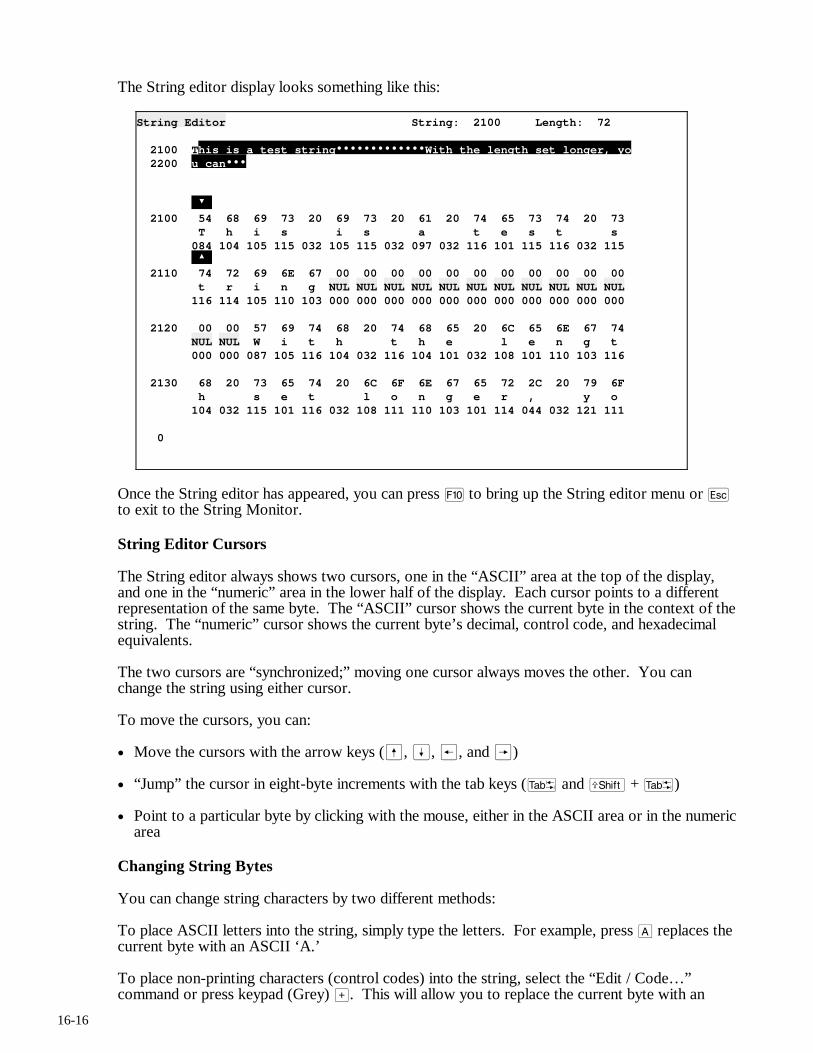
16-16
The String editor display looks something like this:
String Editor String: 2100 Length: 72 2100 This is a test string With the length set longer, yo 2200 u can 2100 54 68 69 73 20 69 73 20 61 20 74 65 73 74 20 73 T h i s i s a t e s t s 084 104 105 115 032 105 115 032 097 032 116 101 115 116 032 115 2110 74 72 69 6E 67 00 00 00 00 00 00 00 00 00 00 00 t r i n g NUL NUL NUL NUL NUL NUL NUL NUL NUL NUL NUL 116 114 105 110 103 000 000 000 000 000 000 000 000 000 000 000 2120 00 00 57 69 74 68 20 74 68 65 20 6C 65 6E 67 74 NUL NUL W i t h t h e l e n g t 000 000 087 105 116 104 032 116 104 101 032 108 101 110 103 116 2130 68 20 73 65 74 20 6C 6F 6E 67 65 72 2C 20 79 6F h s e t l o n g e r , y o 104 032 115 101 116 032 108 111 110 103 101 114 044 032 121 111 0
Once the String editor has appeared, you can press ) to bring up the String editor menu or q to exit to the String Monitor.
String Editor Cursors
The String editor always shows two cursors, one in the “ASCII” area at the top of the display, and one in the “numeric” area in the lower half of the display. Each cursor points to a different representation of the same byte. The “ASCII” cursor shows the current byte in the context of the string. The “numeric” cursor shows the current byte’s decimal, control code, and hexadecimal equivalents.
The two cursors are “synchronized;” moving one cursor always moves the other. You can change the string using either cursor.
To move the cursors, you can:
• Move the cursors with the arrow keys (ß, Í, ®, and Â)
• “Jump” the cursor in eight-byte increments with the tab keys (t and f + t)
• Point to a particular byte by clicking with the mouse, either in the ASCII area or in the numeric area
Changing String Bytes
You can change string characters by two different methods:
To place ASCII letters into the string, simply type the letters. For example, press A replaces the current byte with an ASCII ‘A.’
To place non-printing characters (control codes) into the string, select the “Edit / Code…” command or press keypad (Grey) >. This will allow you to replace the current byte with an
16-17
arbitrary value. When the “Enter Code” dialog box appears, you can enter: an ASCII code name (e.g. “esc” for Escape, equivalent to 27 decimal); a decimal number; a hexadecimal number preceded by ‘h’ (e.g, “h20” will insert an ASCII blank, 32 decimal); or an octal number preceded by ‘o’ (“o40” will add a blank, 32 decimal). Press q to cancel the operation.
16.7.2. Shortcut Keys
The following shortcut keys are available while in the String Monitor:
Key Function
i Inserts a character into the string
d Deletes a character from the string
c + V Online only. Pause and restart monitoring the current string
keypad (Grey) >
Replaces the current character with a numeric or control code
) Bring up the String editor menu
t Advance cursor to next eight-byte boundary
f + t Back up cursor to last eight-byte boundary
16.7.3. Return
The Return menu command returns to the String Monitor. Pressing q will also exit to the String Monitor.
16.7.4. Edit
The Edit menu contains the commands used to edit strings. They are described below.
16.7.4.1. Insert
Shortcut key: i
The Insert command inserts a blank (ASCII 32) at the current cursor position. All bytes to the right will be moved to the right to make room for the new character. The last byte of the string will be lost.
16.7.4.2. Delete
Shortcut key: d
The Delete command removes the current character. All following bytes will move left to fill the gap. An ASCII “NUL” (00) will be added at the end of the string.
16.7.4.3. Code…
Shortcut key: keypad (Grey) >
The Code command uses a dialog box to replace the current byte with a new code entered as a number or as an ASCII control code.
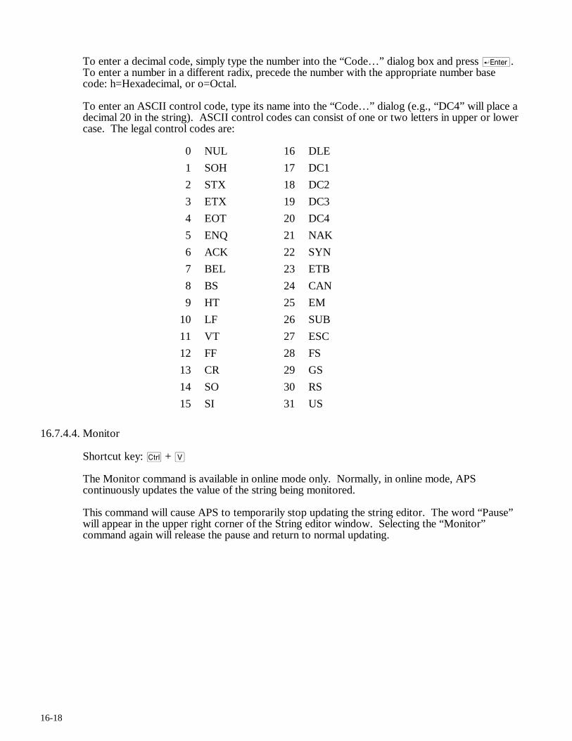
16-18
To enter a decimal code, simply type the number into the “Code…” dialog box and press r. To enter a number in a different radix, precede the number with the appropriate number base code: h=Hexadecimal, or o=Octal.
To enter an ASCII control code, type its name into the “Code…” dialog (e.g., “DC4” will place a decimal 20 in the string). ASCII control codes can consist of one or two letters in upper or lower case. The legal control codes are:
0 NUL 16 DLE
1 SOH 17 DC1
2 STX 18 DC2
3 ETX 19 DC3
4 EOT 20 DC4
5 ENQ 21 NAK
6 ACK 22 SYN
7 BEL 23 ETB
8 BS 24 CAN
9 HT 25 EM
10 LF 26 SUB
11 VT 27 ESC
12 FF 28 FS
13 CR 29 GS
14 SO 30 RS
15 SI 31 US
16.7.4.4. Monitor
Shortcut key: c + V
The Monitor command is available in online mode only. Normally, in online mode, APS continuously updates the value of the string being monitored.
This command will cause APS to temporarily stop updating the string editor. The word “Pause” will appear in the upper right corner of the String editor window. Selecting the “Monitor” command again will release the pause and return to normal updating.
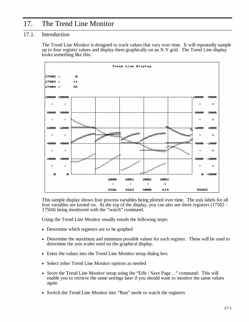
17-1
17. The Trend Line Monitor
17.1. Introduction
The Trend Line Monitor is designed to track values that vary over time. It will repeatedly sample up to four register values and display them graphically on an X-Y grid. The Trend Line display looks something like this:
This sample display shows four process variables being plotted over time. The axis labels for all four variables are turned on. At the top of the display, you can also see three registers (17502 - 17504) being monitored with the “watch” command.
Using the Trend Line Monitor usually entails the following steps:
• Determine which registers are to be graphed
• Determine the maximum and minimum possible values for each register. These will be used to determine the axis scales used on the graphical display.
• Enter the values into the Trend Line Monitor setup dialog box
• Select other Trend Line Monitor options as needed
• Store the Trend Line Monitor setup using the “Edit / Save Page…” command. This will enable you to retrieve the same settings later if you should want to monitor the same values again
• Switch the Trend Line Monitor into “Run” mode to watch the registers
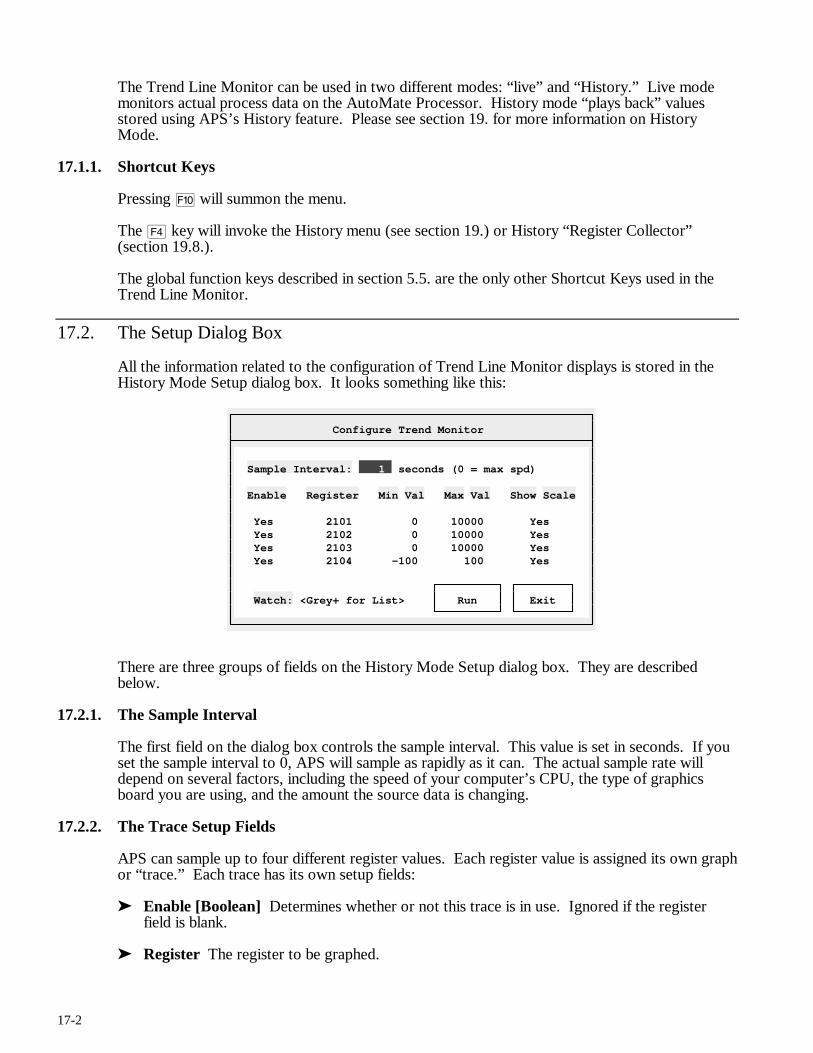
17-2
The Trend Line Monitor can be used in two different modes: “live” and “History.” Live mode monitors actual process data on the AutoMate Processor. History mode “plays back” values stored using APS’s History feature. Please see section 19. for more information on History Mode.
17.1.1. Shortcut Keys
Pressing ) will summon the menu.
The $ key will invoke the History menu (see section 19.) or History “Register Collector” (section 19.8.).
The global function keys described in section 5.5. are the only other Shortcut Keys used in the Trend Line Monitor.
17.2. The Setup Dialog Box
All the information related to the configuration of Trend Line Monitor displays is stored in the History Mode Setup dialog box. It looks something like this:
Configure Trend Monitor
Sample Interval: 1 seconds (0 = max spd) Enable Register Min Val Max Val Show Scale Yes 2101 0 10000 Yes Yes 2102 0 10000 Yes Yes 2103 0 10000 Yes Yes 2104 -100 100 Yes Watch: <Grey+ for List> Run Exit
There are three groups of fields on the History Mode Setup dialog box. They are described below.
17.2.1. The Sample Interval
The first field on the dialog box controls the sample interval. This value is set in seconds. If you set the sample interval to 0, APS will sample as rapidly as it can. The actual sample rate will depend on several factors, including the speed of your computer’s CPU, the type of graphics board you are using, and the amount the source data is changing.
17.2.2. The Trace Setup Fields
APS can sample up to four different register values. Each register value is assigned its own graph or “trace.” Each trace has its own setup fields:
➤ Enable [Boolean] Determines whether or not this trace is in use. Ignored if the register field is blank.
➤ Register The register to be graphed.
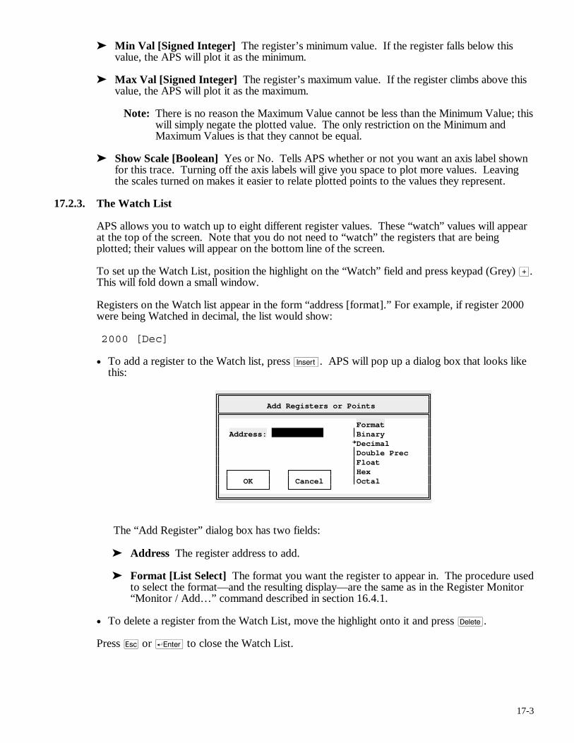
17-3
➤ Min Val [Signed Integer] The register’s minimum value. If the register falls below this value, the APS will plot it as the minimum.
➤ Max Val [Signed Integer] The register’s maximum value. If the register climbs above this value, the APS will plot it as the maximum.
Note: There is no reason the Maximum Value cannot be less than the Minimum Value; this will simply negate the plotted value. The only restriction on the Minimum and Maximum Values is that they cannot be equal.
➤ Show Scale [Boolean] Yes or No. Tells APS whether or not you want an axis label shown for this trace. Turning off the axis labels will give you space to plot more values. Leaving the scales turned on makes it easier to relate plotted points to the values they represent.
17.2.3. The Watch List
APS allows you to watch up to eight different register values. These “watch” values will appear at the top of the screen. Note that you do not need to “watch” the registers that are being plotted; their values will appear on the bottom line of the screen.
To set up the Watch List, position the highlight on the “Watch” field and press keypad (Grey) >. This will fold down a small window.
Registers on the Watch list appear in the form “address [format].” For example, if register 2000 were being Watched in decimal, the list would show:
2000 [Dec]
• To add a register to the Watch list, press i. APS will pop up a dialog box that looks like this:
Add Registers or Points
Format Address: Binary Decimal Double Prec Float Hex OK Cancel Octal
The “Add Register” dialog box has two fields:
➤ Address The register address to add.
➤ Format [List Select] The format you want the register to appear in. The procedure used to select the format—and the resulting display—are the same as in the Register Monitor “Monitor / Add…” command described in section 16.4.1.
• To delete a register from the Watch List, move the highlight onto it and press d.
Press q or r to close the Watch List.
17-4
17.3. The File Menu
The File Menu is available throughout APS. It is used to open new projects, go online, and so forth. The File Menu is described in section 6.
17.4. The Select Menu
Throughout APS, the Select menu is used to switch from one section of the program to another. To leave the current APS section and switch to another section, press ) (or click the right mouse button) to summon the menu, then press S to pull down the Select menu. Choose the new section from the menu.
17.5. The Edit Menu
The Trend Line Monitor Edit menu is used to save and load Trend Line parameters and to initiate the Trend Line Monitor. The Edit menu commands are described below.
17.5.1. Load Page…
The “Load Page…” command loads a Trend Line Monitor definition previously stored with the “Edit / Save Page…” command. The procedure used to load stored Trend Line Monitor definitions is the same as that described in section 16.4.5. (Register Monitor / Monitor / Load Page…).
17.5.2. Save Page…
The “Save Page…” command saves a Trend Line Monitor definition so it can be retrieved later with the “Edit / Load Page…” command. The procedure used to store Trend Line Monitor definitions is the same as that described in section 16.4.6. (Register Monitor / Monitor / Save Page…).
17.5.3. Run
The Run command starts the graphical Trend Line Monitor. Once the display has appeared, it will continue sampling at the rate you have chosen until you press ) or click a mouse button. Pressing the y will temporarily pause the Trend Line Monitor; press y again to release the pause.
Certain other keys are valid when the Trend Line Monitor is used in History mode. Section 19. describes these keys in detail.
You can also start the Trend Line Monitor by clicking on the Setup Dialog Box’s “Run” button with the left mouse button.
17.6. The Utility Menu
The Utility Menu is available throughout APS. It is used to configure printers, set communications parameters, and so forth. The Utility Menu is described in section 7.
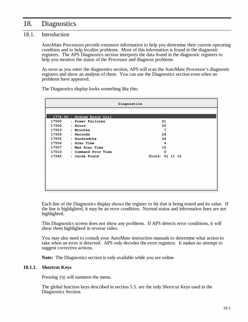
18-1
18. Diagnostics
18.1. Introduction
AutoMate Processors provide extensive information to help you determine their current operating condition and to help localize problems. Most of this information is found in the diagnostic registers. The APS Diagnostics section interprets the data found in the diagnostic registers to help you monitor the status of the Processor and diagnose problems.
As soon as you enter the diagnostics section, APS will scan the AutoMate Processor’s diagnostic registers and show an analysis of them. You can use the Diagnostics section even when no problems have appeared.
The Diagnostics display looks something like this:
Diagnostics
1776.00 : System Error Coil 17500 : Power Failures 21 17502 : Hours 20 17503 : Minutes 7 17504 : Seconds 24 17505 : Hundredths 24 17506 : Scan Time 4 17507 : Max Scan Time 10 17510 : Command Proc Time 0 17565 : Cards Found Slots: 01 11 12
Each line of the Diagnostics display shows the register or bit that is being tested and its value. If the line is highlighted, it may be an error condition. Normal status and information lines are not highlighted.
This Diagnostics screen does not show any problems. If APS detects error conditions, it will show them highlighted in reverse video.
You may also need to consult your AutoMate instruction manuals to determine what action to take when an error is detected. APS only decodes the error registers. It makes no attempt to suggest corrective actions.
Note: The Diagnostics section is only available while you are online.
18.1.1. Shortcut Keys
Pressing ) will summon the menu.
The global function keys described in section 5.5. are the only Shortcut Keys used in the Diagnostics Section.
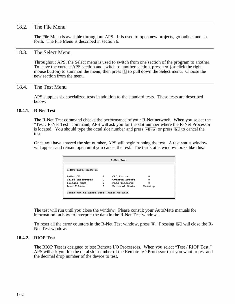
18-2
18.2. The File Menu
The File Menu is available throughout APS. It is used to open new projects, go online, and so forth. The File Menu is described in section 6.
18.3. The Select Menu
Throughout APS, the Select menu is used to switch from one section of the program to another. To leave the current APS section and switch to another section, press ) (or click the right mouse button) to summon the menu, then press S to pull down the Select menu. Choose the new section from the menu.
18.4. The Test Menu
APS supplies six specialized tests in addition to the standard tests. These tests are described below.
18.4.1. R-Net Test
The R-Net Test command checks the performance of your R-Net network. When you select the “Test / R-Net Test” command, APS will ask you for the slot number where the R-Net Processor is located. You should type the octal slot number and press r or press q to cancel the test.
Once you have entered the slot number, APS will begin running the test. A test status window will appear and remain open until you cancel the test. The test status window looks like this:
R-Net Test
R-Net Test, Slot 11 R-Net OK 1 CRC Errors 0 False Interrupts 0 Overrun Errors 0 Illegal Msgs 0 Pass Timeouts 0 Lost Tokens 0 Protocol State Passing Press <R> to Reset Test, <Esc> to Exit
The test will run until you close the window. Please consult your AutoMate manuals for information on how to interpret the data in the R-Net Test window.
To reset all the error counters in the R-Net Test window, press R. Pressing q will close the R-Net Test window.
18.4.2. RIOP Test
The RIOP Test is designed to test Remote I/O Processors. When you select “Test / RIOP Test,” APS will ask you for the octal slot number of the Remote I/O Processor that you want to test and the decimal drop number of the device to test.
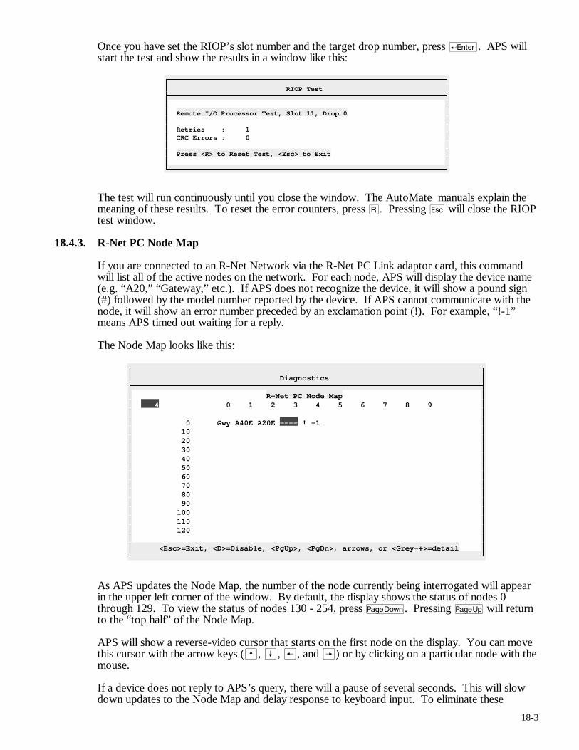
18-3
Once you have set the RIOP’s slot number and the target drop number, press r. APS will start the test and show the results in a window like this:
RIOP Test
Remote I/O Processor Test, Slot 11, Drop 0 Retries : 1 CRC Errors : 0 Press <R> to Reset Test, <Esc> to Exit
The test will run continuously until you close the window. The AutoMate manuals explain the meaning of these results. To reset the error counters, press R. Pressing q will close the RIOP test window.
18.4.3. R-Net PC Node Map
If you are connected to an R-Net Network via the R-Net PC Link adaptor card, this command will list all of the active nodes on the network. For each node, APS will display the device name (e.g. “A20,” “Gateway,” etc.). If APS does not recognize the device, it will show a pound sign (#) followed by the model number reported by the device. If APS cannot communicate with the node, it will show an error number preceded by an exclamation point (!). For example, “!-1” means APS timed out waiting for a reply.
The Node Map looks like this:
Diagnostics
R-Net PC Node Map 4 0 1 2 3 4 5 6 7 8 9 0 Gwy A40E A20E ---- ! -1 10 20 30 40 50 60 70 80 90 100 110 120 <Esc>=Exit, <D>=Disable, <PgUp>, <PgDn>, arrows, or <Grey-+>=detail
As APS updates the Node Map, the number of the node currently being interrogated will appear in the upper left corner of the window. By default, the display shows the status of nodes 0 through 129. To view the status of nodes 130 - 254, press v. Pressing u will return to the “top half” of the Node Map.
APS will show a reverse-video cursor that starts on the first node on the display. You can move this cursor with the arrow keys (ß, Í, ®, and Â) or by clicking on a particular node with the mouse.
If a device does not reply to APS’s query, there will a pause of several seconds. This will slow down updates to the Node Map and delay response to keyboard input. To eliminate these
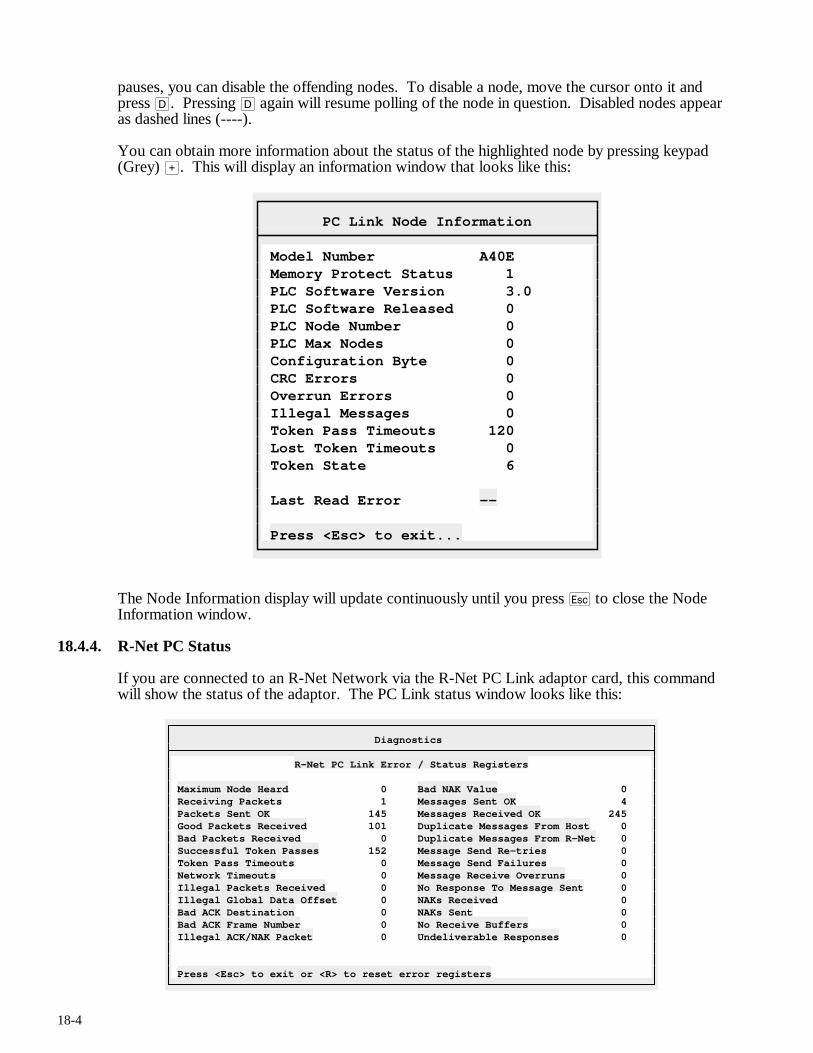
18-4
pauses, you can disable the offending nodes. To disable a node, move the cursor onto it and press D. Pressing D again will resume polling of the node in question. Disabled nodes appear as dashed lines (----).
You can obtain more information about the status of the highlighted node by pressing keypad (Grey) >. This will display an information window that looks like this:
PC Link Node Information
Model Number A40E Memory Protect Status 1 PLC Software Version 3.0 PLC Software Released 0 PLC Node Number 0 PLC Max Nodes 0 Configuration Byte 0 CRC Errors 0 Overrun Errors 0 Illegal Messages 0 Token Pass Timeouts 120 Lost Token Timeouts 0 Token State 6 Last Read Error -- Press <Esc> to exit...
The Node Information display will update continuously until you press q to close the Node Information window.
18.4.4. R-Net PC Status
If you are connected to an R-Net Network via the R-Net PC Link adaptor card, this command will show the status of the adaptor. The PC Link status window looks like this:
Diagnostics
R-Net PC Link Error / Status Registers Maximum Node Heard 0 Bad NAK Value 0 Receiving Packets 1 Messages Sent OK 4 Packets Sent OK 145 Messages Received OK 245 Good Packets Received 101 Duplicate Messages From Host 0 Bad Packets Received 0 Duplicate Messages From R-Net 0 Successful Token Passes 152 Message Send Re-tries 0 Token Pass Timeouts 0 Message Send Failures 0 Network Timeouts 0 Message Receive Overruns 0 Illegal Packets Received 0 No Response To Message Sent 0 Illegal Global Data Offset 0 NAKs Received 0 Bad ACK Destination 0 NAKs Sent 0 Bad ACK Frame Number 0 No Receive Buffers 0 Illegal ACK/NAK Packet 0 Undeliverable Responses 0 Press <Esc> to exit or <R> to reset error registers
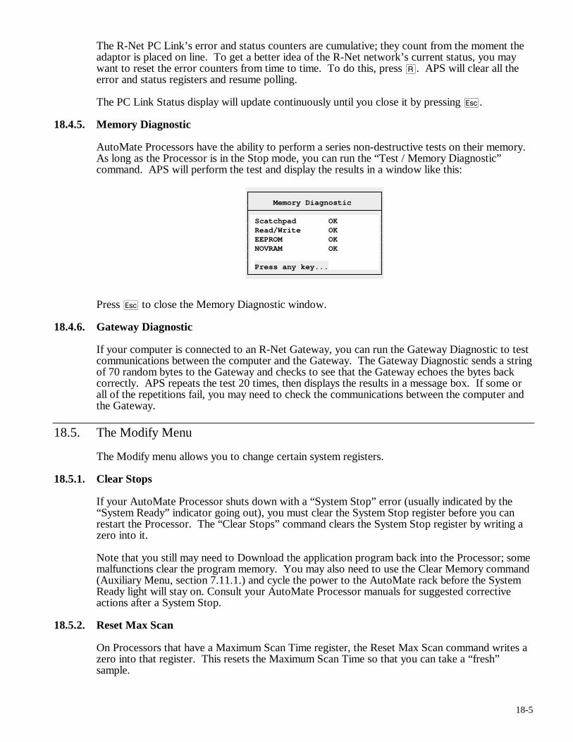
18-5
The R-Net PC Link’s error and status counters are cumulative; they count from the moment the adaptor is placed on line. To get a better idea of the R-Net network’s current status, you may want to reset the error counters from time to time. To do this, press R. APS will clear all the error and status registers and resume polling.
The PC Link Status display will update continuously until you close it by pressing q.
18.4.5. Memory Diagnostic
AutoMate Processors have the ability to perform a series non-destructive tests on their memory. As long as the Processor is in the Stop mode, you can run the “Test / Memory Diagnostic” command. APS will perform the test and display the results in a window like this:
Memory Diagnostic
Scatchpad OK Read/Write OK EEPROM OK NOVRAM OK Press any key...
Press q to close the Memory Diagnostic window.
18.4.6. Gateway Diagnostic
If your computer is connected to an R-Net Gateway, you can run the Gateway Diagnostic to test communications between the computer and the Gateway. The Gateway Diagnostic sends a string of 70 random bytes to the Gateway and checks to see that the Gateway echoes the bytes back correctly. APS repeats the test 20 times, then displays the results in a message box. If some or all of the repetitions fail, you may need to check the communications between the computer and the Gateway.
18.5. The Modify Menu
The Modify menu allows you to change certain system registers.
18.5.1. Clear Stops
If your AutoMate Processor shuts down with a “System Stop” error (usually indicated by the “System Ready” indicator going out), you must clear the System Stop register before you can restart the Processor. The “Clear Stops” command clears the System Stop register by writing a zero into it.
Note that you still may need to Download the application program back into the Processor; some malfunctions clear the program memory. You may also need to use the Clear Memory command (Auxiliary Menu, section 7.11.1.) and cycle the power to the AutoMate rack before the System Ready light will stay on. Consult your AutoMate Processor manuals for suggested corrective actions after a System Stop.
18.5.2. Reset Max Scan
On Processors that have a Maximum Scan Time register, the Reset Max Scan command writes a zero into that register. This resets the Maximum Scan Time so that you can take a “fresh” sample.
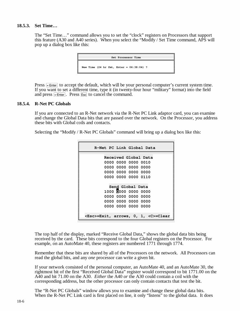
18-6
18.5.3. Set Time…
The “Set Time…” command allows you to set the “clock” registers on Processors that support this feature (A30 and A40 series). When you select the “Modify / Set Time command, APS will pop up a dialog box like this:
Set Processor Time
New Time (24 hr fmt, Enter = 06:38:04) ?
Press r to accept the default, which will be your personal computer’s current system time. If you want to set a different time, type it (in twenty-four hour “military” format) into the field and press r. Press q to cancel the command.
18.5.4. R-Net PC Globals
If you are connected to an R-Net network via the R-Net PC Link adaptor card, you can examine and change the Global Data bits that are passed over the network. On the Processor, you address these bits with Global coils and contacts.
Selecting the “Modify / R-Net PC Globals” command will bring up a dialog box like this:
R-Net PC Link Global Data
Received Global Data 0000 0000 0000 0010 0000 0000 0000 0000 0000 0000 0000 0000 0000 0000 0000 0110 Send Global Data 1000 0000 0000 0000 0000 0000 0000 0000 0000 0000 0000 0000 0000 0000 0000 0000 <Esc>=Exit, arrows, 0, 1, <C>=Clear
The top half of the display, marked “Receive Global Data,” shows the global data bits being received by the card. These bits correspond to the four Global registers on the Processor. For example, on an AutoMate 40, these registers are numbered 1771 through 1774.
Remember that these bits are shared by all of the Processors on the network. All Processors can read the global bits, and any one processor can write a given bit.
If your network consisted of the personal computer, an AutoMate 40, and an AutoMate 30, the rightmost bit of the first “Received Global Data” register would correspond to bit 1771.00 on the A40 and bit 71.00 on the A30. Either the A40 or the A30 could contain a coil with the corresponding address, but the other processor can only contain contacts that test the bit.
The “R-Net PC Globals” window allows you to examine and change these global data bits. When the R-Net PC Link card is first placed on line, it only “listens” to the global data. It does
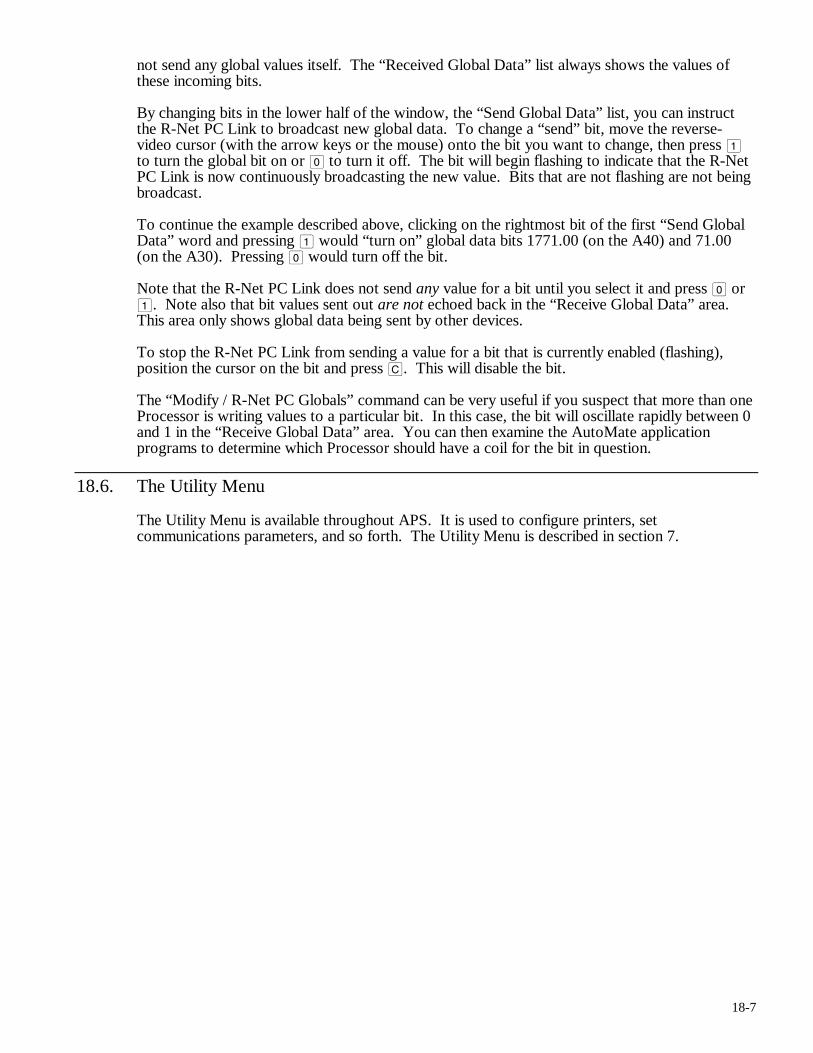
18-7
not send any global values itself. The “Received Global Data” list always shows the values of these incoming bits.
By changing bits in the lower half of the window, the “Send Global Data” list, you can instruct the R-Net PC Link to broadcast new global data. To change a “send” bit, move the reverse-video cursor (with the arrow keys or the mouse) onto the bit you want to change, then press 1 to turn the global bit on or 0 to turn it off. The bit will begin flashing to indicate that the R-Net PC Link is now continuously broadcasting the new value. Bits that are not flashing are not being broadcast.
To continue the example described above, clicking on the rightmost bit of the first “Send Global Data” word and pressing 1 would “turn on” global data bits 1771.00 (on the A40) and 71.00 (on the A30). Pressing 0 would turn off the bit.
Note that the R-Net PC Link does not send any value for a bit until you select it and press 0 or 1. Note also that bit values sent out are not echoed back in the “Receive Global Data” area. This area only shows global data being sent by other devices.
To stop the R-Net PC Link from sending a value for a bit that is currently enabled (flashing), position the cursor on the bit and press C. This will disable the bit.
The “Modify / R-Net PC Globals” command can be very useful if you suspect that more than one Processor is writing values to a particular bit. In this case, the bit will oscillate rapidly between 0 and 1 in the “Receive Global Data” area. You can then examine the AutoMate application programs to determine which Processor should have a coil for the bit in question.
18.6. The Utility Menu
The Utility Menu is available throughout APS. It is used to configure printers, set communications parameters, and so forth. The Utility Menu is described in section 7.

19-1
19. History Mode
19.1. Introduction
APS provides a simple built-in data logger and report generator system, which is known as History mode. APS’s History system can log data, print reports, and “replay” data thorough its monitoring displays. For example, you could log data overnight, then come back in the morning and “watch” the night’s events by playing back data through the Register Monitor and the Sequence Monitor. History files can be set up to log only when certain conditions exist, or to log until a particular event occurs, and so forth.
When you first enter History mode, APS will display the History Status Window, which will contain the message “No History Configuration Set.” Before you can log data, you must establish a History mode configuration, either by entering a new configuration or by loading one that has been previously stored. To play back data, you must open an existing History log file.
The general History process is:
• Configure a History file using the “Record / Configure…” command.
• Define a list of registers to be logged. To do this, you can add them with the “Record / Configure…” command, or you can use the “History / Add Register List” (see section 19.8.) feature to “collect” registers to log from monitoring displays.
• Save the History configuration for later reuse with the “Record / Save Page…” command.
• Start the data logger (while online) using the “Record / Start Recorder” command. You can continue to perform other online tasks while the logger runs.
• Play back data from a History file using the “Playback / File…” command. In History Playback mode, APS’s monitoring functions work just as they do online, but they read data from the log file instead of the AutoMate Processor.
• Print reports using the “Report / Configure Report…” and “Record / Print Report…” commands.
• Export History data for use by database or spreadsheet programs using the Report command.
19.1.1. Shortcut Keys
Pressing ) will, as usual, summon the menu.
The global function keys described in section 5.5. are the only Shortcut Keys used in the History Section.
19.2. The File Menu
The File Menu is available throughout APS. It is used to open new projects, go online, and so forth. The File Menu is described in section 6.
19.3. The Select Menu
Throughout APS, the Select menu is used to switch from one section of the program to another. To leave the current APS section and switch to another section, press ) (or click the right mouse button) to summon the menu, then press S to pull down the Select menu. Choose the new section from the menu.
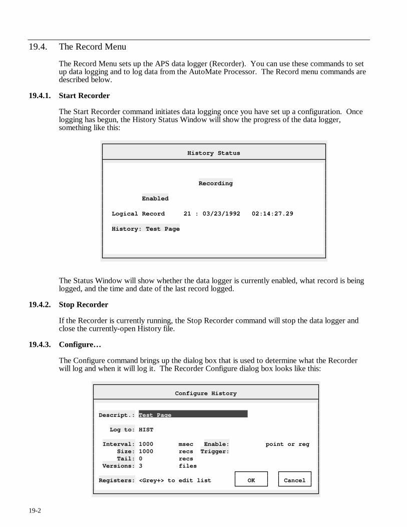
19-2
19.4. The Record Menu
The Record Menu sets up the APS data logger (Recorder). You can use these commands to set up data logging and to log data from the AutoMate Processor. The Record menu commands are described below.
19.4.1. Start Recorder
The Start Recorder command initiates data logging once you have set up a configuration. Once logging has begun, the History Status Window will show the progress of the data logger, something like this:
History Status
Recording Enabled Logical Record 21 : 03/23/1992 02:14:27.29 History: Test Page
The Status Window will show whether the data logger is currently enabled, what record is being logged, and the time and date of the last record logged.
19.4.2. Stop Recorder
If the Recorder is currently running, the Stop Recorder command will stop the data logger and close the currently-open History file.
19.4.3. Configure…
The Configure command brings up the dialog box that is used to determine what the Recorder will log and when it will log it. The Recorder Configure dialog box looks like this:
Configure History
Descript.: Test Page Log to: HIST Interval: 1000 msec Enable: point or reg Size: 1000 recs Trigger: Tail: 0 recs Versions: 3 files Registers: <Grey+> to edit list OK Cancel
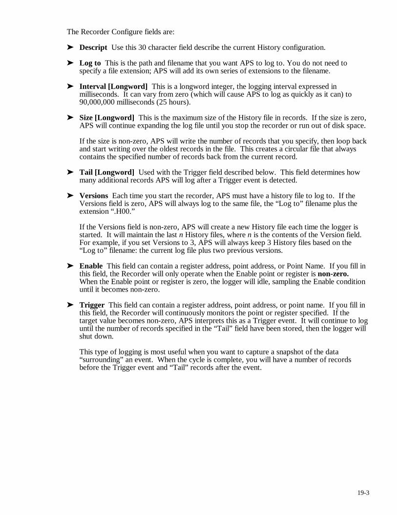
19-3
The Recorder Configure fields are:
➤ Descript Use this 30 character field describe the current History configuration.
➤ Log to This is the path and filename that you want APS to log to. You do not need to specify a file extension; APS will add its own series of extensions to the filename.
➤ Interval [Longword] This is a longword integer, the logging interval expressed in milliseconds. It can vary from zero (which will cause APS to log as quickly as it can) to 90,000,000 milliseconds (25 hours).
➤ Size [Longword] This is the maximum size of the History file in records. If the size is zero, APS will continue expanding the log file until you stop the recorder or run out of disk space.
If the size is non-zero, APS will write the number of records that you specify, then loop back and start writing over the oldest records in the file. This creates a circular file that always contains the specified number of records back from the current record.
➤ Tail [Longword] Used with the Trigger field described below. This field determines how many additional records APS will log after a Trigger event is detected.
➤ Versions Each time you start the recorder, APS must have a history file to log to. If the Versions field is zero, APS will always log to the same file, the “Log to” filename plus the extension “.H00.”
If the Versions field is non-zero, APS will create a new History file each time the logger is started. It will maintain the last n History files, where n is the contents of the Version field. For example, if you set Versions to 3, APS will always keep 3 History files based on the “Log to” filename: the current log file plus two previous versions.
➤ Enable This field can contain a register address, point address, or Point Name. If you fill in this field, the Recorder will only operate when the Enable point or register is non-zero. When the Enable point or register is zero, the logger will idle, sampling the Enable condition until it becomes non-zero.
➤ Trigger This field can contain a register address, point address, or point name. If you fill in this field, the Recorder will continuously monitors the point or register specified. If the target value becomes non-zero, APS interprets this as a Trigger event. It will continue to log until the number of records specified in the “Tail” field have been stored, then the logger will shut down.
This type of logging is most useful when you want to capture a snapshot of the data “surrounding” an event. When the cycle is complete, you will have a number of records before the Trigger event and “Tail” records after the event.
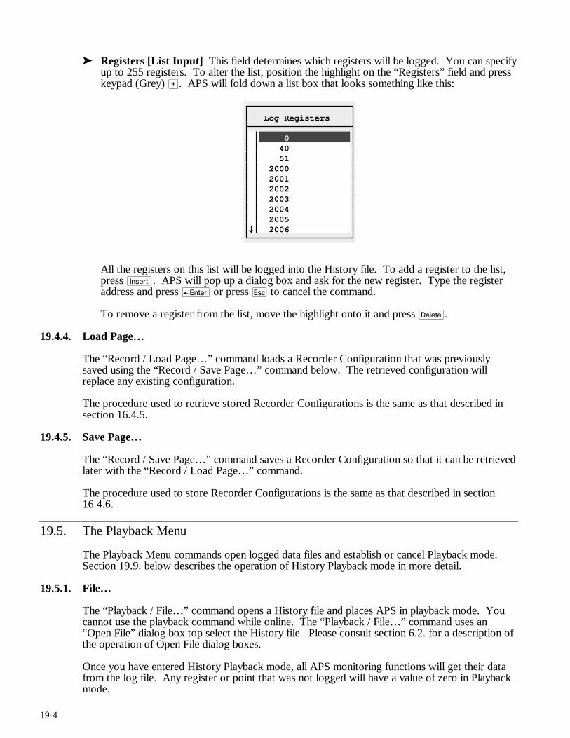
19-4
➤ Registers [List Input] This field determines which registers will be logged. You can specify up to 255 registers. To alter the list, position the highlight on the “Registers” field and press keypad (Grey) >. APS will fold down a list box that looks something like this:
Log Registers
0 40 51 2000 2001 2002 2003 2004 2005
2006
All the registers on this list will be logged into the History file. To add a register to the list, press i. APS will pop up a dialog box and ask for the new register. Type the register address and press r or press q to cancel the command.
To remove a register from the list, move the highlight onto it and press d.
19.4.4. Load Page…
The “Record / Load Page…” command loads a Recorder Configuration that was previously saved using the “Record / Save Page…” command below. The retrieved configuration will replace any existing configuration.
The procedure used to retrieve stored Recorder Configurations is the same as that described in section 16.4.5.
19.4.5. Save Page…
The “Record / Save Page…” command saves a Recorder Configuration so that it can be retrieved later with the “Record / Load Page…” command.
The procedure used to store Recorder Configurations is the same as that described in section 16.4.6.
19.5. The Playback Menu
The Playback Menu commands open logged data files and establish or cancel Playback mode. Section 19.9. below describes the operation of History Playback mode in more detail.
19.5.1. File…
The “Playback / File…” command opens a History file and places APS in playback mode. You cannot use the playback command while online. The “Playback / File…” command uses an “Open File” dialog box top select the History file. Please consult section 6.2. for a description of the operation of Open File dialog boxes.
Once you have entered History Playback mode, all APS monitoring functions will get their data from the log file. Any register or point that was not logged will have a value of zero in Playback mode.
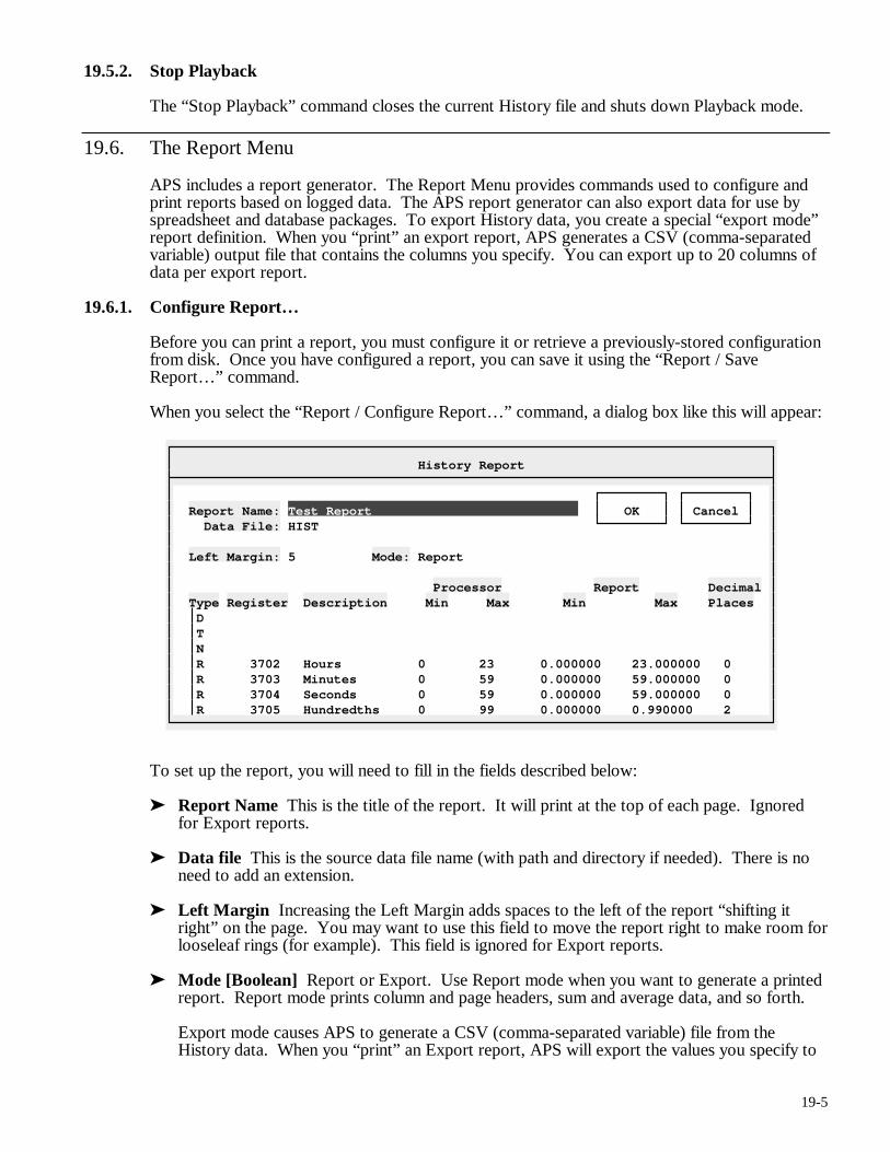
19-5
19.5.2. Stop Playback
The “Stop Playback” command closes the current History file and shuts down Playback mode.
19.6. The Report Menu
APS includes a report generator. The Report Menu provides commands used to configure and print reports based on logged data. The APS report generator can also export data for use by spreadsheet and database packages. To export History data, you create a special “export mode” report definition. When you “print” an export report, APS generates a CSV (comma-separated variable) output file that contains the columns you specify. You can export up to 20 columns of data per export report.
19.6.1. Configure Report…
Before you can print a report, you must configure it or retrieve a previously-stored configuration from disk. Once you have configured a report, you can save it using the “Report / Save Report…” command.
When you select the “Report / Configure Report…” command, a dialog box like this will appear:
History Report
Report Name: Test Report OK Cancel Data File: HIST Left Margin: 5 Mode: Report Processor Report Decimal Type Register Description Min Max Min Max Places D T N R 3702 Hours 0 23 0.000000 23.000000 0 R 3703 Minutes 0 59 0.000000 59.000000 0 R 3704 Seconds 0 59 0.000000 59.000000 0 R 3705 Hundredths 0 99 0.000000 0.990000 2
To set up the report, you will need to fill in the fields described below:
➤ Report Name This is the title of the report. It will print at the top of each page. Ignored for Export reports.
➤ Data file This is the source data file name (with path and directory if needed). There is no need to add an extension.
➤ Left Margin Increasing the Left Margin adds spaces to the left of the report “shifting it right” on the page. You may want to use this field to move the report right to make room for looseleaf rings (for example). This field is ignored for Export reports.
➤ Mode [Boolean] Report or Export. Use Report mode when you want to generate a printed report. Report mode prints column and page headers, sum and average data, and so forth.
Export mode causes APS to generate a CSV (comma-separated variable) file from the History data. When you “print” an Export report, APS will export the values you specify to
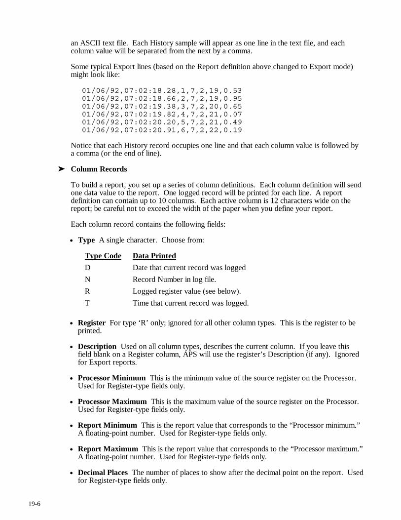
19-6
an ASCII text file. Each History sample will appear as one line in the text file, and each column value will be separated from the next by a comma.
Some typical Export lines (based on the Report definition above changed to Export mode) might look like:
01/06/92,07:02:18.28,1,7,2,19,0.53 01/06/92,07:02:18.66,2,7,2,19,0.95 01/06/92,07:02:19.38,3,7,2,20,0.65 01/06/92,07:02:19.82,4,7,2,21,0.07 01/06/92,07:02:20.20,5,7,2,21,0.49 01/06/92,07:02:20.91,6,7,2,22,0.19
Notice that each History record occupies one line and that each column value is followed by a comma (or the end of line).
➤ Column Records
To build a report, you set up a series of column definitions. Each column definition will send one data value to the report. One logged record will be printed for each line. A report definition can contain up to 10 columns. Each active column is 12 characters wide on the report; be careful not to exceed the width of the paper when you define your report.
Each column record contains the following fields:
• Type A single character. Choose from:
Type Code Data Printed
D Date that current record was logged
N Record Number in log file.
R Logged register value (see below).
T Time that current record was logged.
• Register For type ‘R’ only; ignored for all other column types. This is the register to be printed.
• Description Used on all column types, describes the current column. If you leave this field blank on a Register column, APS will use the register’s Description (if any). Ignored for Export reports.
• Processor Minimum This is the minimum value of the source register on the Processor. Used for Register-type fields only.
• Processor Maximum This is the maximum value of the source register on the Processor. Used for Register-type fields only.
• Report Minimum This is the report value that corresponds to the “Processor minimum.” A floating-point number. Used for Register-type fields only.
• Report Maximum This is the report value that corresponds to the “Processor maximum.” A floating-point number. Used for Register-type fields only.
• Decimal Places The number of places to show after the decimal point on the report. Used for Register-type fields only.
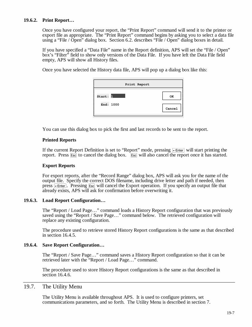
19-7
19.6.2. Print Report…
Once you have configured your report, the “Print Report” command will send it to the printer or export file as appropriate. The “Print Report” command begins by asking you to select a data file using a “File / Open” dialog box. Section 6.2. describes “File / Open” dialog boxes in detail.
If you have specified a “Data File” name in the Report definition, APS will set the “File / Open” box’s “Filter” field to show only versions of the Data File. If you have left the Data File field empty, APS will show all History files.
Once you have selected the History data file, APS will pop up a dialog box like this:
Print Report
Start: 1 OK End: 1000 Cancel
You can use this dialog box to pick the first and last records to be sent to the report.
Printed Reports
If the current Report Definition is set to “Report” mode, pressing r will start printing the report. Press q to cancel the dialog box. q will also cancel the report once it has started.
Export Reports
For export reports, after the “Record Range” dialog box, APS will ask you for the name of the output file. Specify the correct DOS filename, including drive letter and path if needed, then press r. Pressing q will cancel the Export operation. If you specify an output file that already exists, APS will ask for confirmation before overwriting it.
19.6.3. Load Report Configuration…
The “Report / Load Page…” command loads a History Report configuration that was previously saved using the “Report / Save Page…” command below. The retrieved configuration will replace any existing configuration.
The procedure used to retrieve stored History Report configurations is the same as that described in section 16.4.5.
19.6.4. Save Report Configuration…
The “Report / Save Page…” command saves a History Report configuration so that it can be retrieved later with the “Report / Load Page…” command.
The procedure used to store History Report configurations is the same as that described in section 16.4.6.
19.7. The Utility Menu
The Utility Menu is available throughout APS. It is used to configure printers, set communications parameters, and so forth. The Utility Menu is described in section 7.
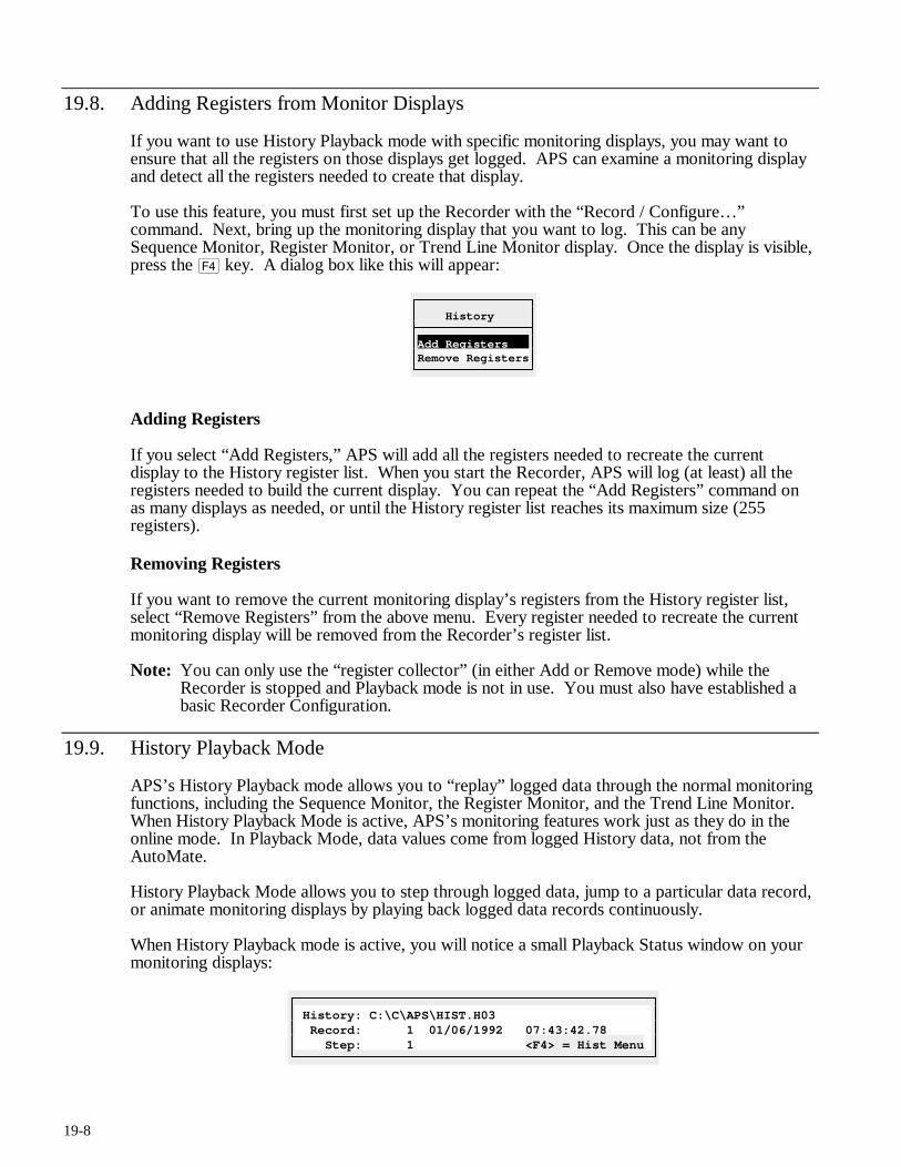
19-8
19.8. Adding Registers from Monitor Displays
If you want to use History Playback mode with specific monitoring displays, you may want to ensure that all the registers on those displays get logged. APS can examine a monitoring display and detect all the registers needed to create that display.
To use this feature, you must first set up the Recorder with the “Record / Configure…” command. Next, bring up the monitoring display that you want to log. This can be any Sequence Monitor, Register Monitor, or Trend Line Monitor display. Once the display is visible, press the $ key. A dialog box like this will appear:
History
Add Registers Remove Registers
Adding Registers
If you select “Add Registers,” APS will add all the registers needed to recreate the current display to the History register list. When you start the Recorder, APS will log (at least) all the registers needed to build the current display. You can repeat the “Add Registers” command on as many displays as needed, or until the History register list reaches its maximum size (255 registers).
Removing Registers
If you want to remove the current monitoring display’s registers from the History register list, select “Remove Registers” from the above menu. Every register needed to recreate the current monitoring display will be removed from the Recorder’s register list.
Note: You can only use the “register collector” (in either Add or Remove mode) while the Recorder is stopped and Playback mode is not in use. You must also have established a basic Recorder Configuration.
19.9. History Playback Mode
APS’s History Playback mode allows you to “replay” logged data through the normal monitoring functions, including the Sequence Monitor, the Register Monitor, and the Trend Line Monitor. When History Playback Mode is active, APS’s monitoring features work just as they do in the online mode. In Playback Mode, data values come from logged History data, not from the AutoMate.
History Playback Mode allows you to step through logged data, jump to a particular data record, or animate monitoring displays by playing back logged data records continuously.
When History Playback mode is active, you will notice a small Playback Status window on your monitoring displays:
History: C:\C\APS\HIST.H03 Record: 1 01/06/1992 07:43:42.78 Step: 1 <F4> = Hist Menu
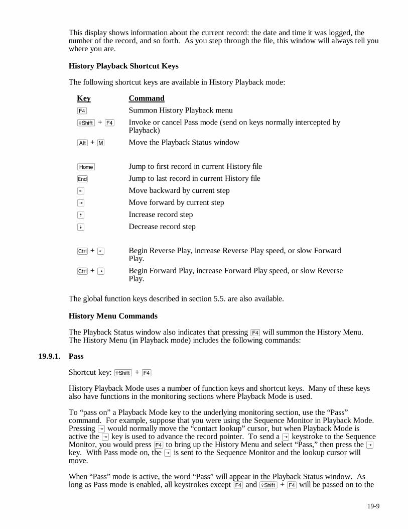
19-9
This display shows information about the current record: the date and time it was logged, the number of the record, and so forth. As you step through the file, this window will always tell you where you are.
History Playback Shortcut Keys
The following shortcut keys are available in History Playback mode:
Key Command
$ Summon History Playback menu
f + $ Invoke or cancel Pass mode (send on keys normally intercepted by Playback)
a + M Move the Playback Status window
m Jump to first record in current History file
e Jump to last record in current History file
® Move backward by current step
 Move forward by current step
ß Increase record step
Í Decrease record step
c + ® Begin Reverse Play, increase Reverse Play speed, or slow Forward Play.
c + Â Begin Forward Play, increase Forward Play speed, or slow Reverse Play.
The global function keys described in section 5.5. are also available.
History Menu Commands
The Playback Status window also indicates that pressing $ will summon the History Menu. The History Menu (in Playback mode) includes the following commands:
19.9.1. Pass
Shortcut key: f + $
History Playback Mode uses a number of function keys and shortcut keys. Many of these keys also have functions in the monitoring sections where Playback Mode is used.
To “pass on” a Playback Mode key to the underlying monitoring section, use the “Pass” command. For example, suppose that you were using the Sequence Monitor in Playback Mode. Pressing  would normally move the “contact lookup” cursor, but when Playback Mode is active the  key is used to advance the record pointer. To send a  keystroke to the Sequence Monitor, you would press $ to bring up the History Menu and select “Pass,” then press the  key. With Pass mode on, the  is sent to the Sequence Monitor and the lookup cursor will move.
When “Pass” mode is active, the word “Pass” will appear in the Playback Status window. As long as Pass mode is enabled, all keystrokes except $ and f + $ will be passed on to the
19-10
underlying function. Pressing either of these keys will cancel Pass mode and return to normal Playback operation.
19.9.2. Move Window
Shortcut key: a + M
You can move the Playback Status window if it is currently covering an area of the screen that you need to be able to see. Pressing a + M or choosing the “Move Window” command will cause the Playback Status window’s “frame” to change to stars (*).
As long as the border is in this state, you can move the window around the screen with the arrow keys (ß, Í, ®, and Â). You can also place the window by clicking with the left mouse button at the place where you want the upper left corner of the window to be.
Once the window is positioned correctly, press r to exit “Move Window” mode.
19.9.3. Goto…
Selecting the “Goto…” command brings up a second level menu, which allows you to choose from:
• First record The first record in the History file.
Shortcut key: m
• Last record The last record in the History file.
Shortcut key: e
• Event If a Trigger condition was defined when the History file was created, and if a Trigger event occurred while the Recorder was active, APS will jump to the first History record after the Event was detected.
19.9.4. Previous Record
Shortcut key: ®
The Previous Record command moves backward in the History file by the current step (see below).
19.9.5. Next Record
Shortcut key: Â
The Next Record command moves forward in the History file by the current step (see below).
19.9.6. Increase Step
Shortcut key: ß
By default, the “Next Record” and “Previous Record” commands move by one record per key press (or menu selection). If you want to move through the file more rapidly, press the ß key. You will see the “Step” indicator in the Playback Status window increase by one for each press.
After you have changed the Step, the “Next” and “Previous” commands will move by “step” records.
19-11
19.9.7. Decrease Step
Shortcut key: Í
The Decrease Step command decreases the current Step by one (see “Increase Step” above).
19.9.8. Play Reverse
Shortcut key: c + ®
When you first enter History Playback Mode, you move the current record by pressing the arrow keys ® and Â. Each keypress moves the current record pointer by “step” records.
APS can also “animate” the playback data by stepping continuously through the History file. In “Play” mode, APS will show each data record in succession, moving forward or backward automatically after a short pause.
When you select the “Play Reverse” command, APS will begin playing records backward. The monitoring display will update with each record, giving an impression somewhat like online monitoring. You can increase the Play speed by selecting the “Play Reverse” command again (or by pressing c + ®). There are a total of six playback speeds. The current speed is indicated by the number of ‘<’ symbols in the Playback Status window.
To slow down (or stop) “Play Reverse” mode, press c + Â or select the “Play Forward” command. Reverse Play mode will stop when no ‘<’ symbols are left in the Playback Status window.
You can also stop Play mode by pressing the y.
19.9.9. Play Forward
Shortcut key: c + Â
The “Play Forward” command is similar to the “Play Reverse” command except that it moves forward through the History data. This command also slows or stops Reverse Play mode.
As in “Play Reverse,” you can speed up Forward Play mode by selecting the “Play Forward” command repeatedly (or by pressing c + Â). To slow down Forward Play mode, press c + ® or select the “Play Reverse” command from the History menu.
You can also stop Play mode by pressing the y.
19.9.10. Help
Shortcut key: !
The Help command brings up Help information about History Playback mode.

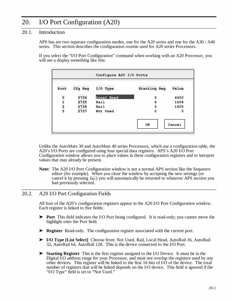
20-1
20. I/O Port Configuration (A20)
20.1. Introduction
APS has are two separate configuration modes, one for the A20 series and one for the A30 / A40 series. This section describes the configuration routine used for A20 series Processors.
If you select the “I/O Port Configuration” command when working with an A20 Processor, you will see a display something like this:
Configure A20 I/O Ports
Port Cfg Reg I/O Type Starting Reg Value 0 2734 Local Head 0 6400 1 2735 Rail 4 1604 2 2736 Rail 5 1605 3 2737 Not Used 0 0 OK Cancel
Unlike the AutoMate 30 and AutoMate 40 series Processors, which use a configuration table, the A20’s I/O Ports are configured using four special data registers. APS’s A20 I/O Port Configuration window allows you to place values in these configuration registers and to interpret values that may already be present.
Note: The A20 I/O Port Configuration window is not a normal APS section like the Sequence editor (for example). When you close the window by accepting the new settings (or cancel it by pressing q) you will automatically be returned to whatever APS section you had previously selected.
20.2. A20 I/O Port Configuration Fields
All four of the A20’s configuration registers appear in the A20 I/O Port Configuration window. Each register is linked to five fields:
➤ Port This field indicates the I/O Port being configured. It is read-only; you cannot move the highlight onto the Port field.
➤ Register Read-only. The configuration register associated with the current port.
➤ I/O Type [List Select] Choose from: Not Used, Rail, Local Head, AutoRail 16, AutoRail 32, AutoRail 64, AutoRail 128. This is the device connected to the I/O Port.
➤ Starting Register This is the first register assigned to the I/O Device. It must be in the Digital I/O address range for your Processor, and must not overlap the registers used by any other devices. This register will be linked to the first 16 bits of I/O of the device. The total number of registers that will be linked depends on the I/O device. This field is ignored if the “I/O Type” field is set to “Not Used.”
20-2
➤ Value Read-only. This shows the value that will be placed in the configuration register when you save the new configuration. This is a coded decimal value. To understand the code, you should consult your A20’s documentation.
Since APS computes the correct value automatically, this field is shown for information only. It may also be helpful when examining an existing configuration if that configuration contains invalid codes.
20.3. Updating the Configuration
When you have set the correct configuration information, press r to save your changes. If you are online, the new configuration will be saved to the AutoMate Processor and to the computer’s memory simultaneously.
You can cancel your configuration changes by pressing q.
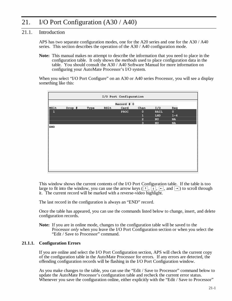
21-1
21. I/O Port Configuration (A30 / A40)
21.1. Introduction
APS has two separate configuration modes, one for the A20 series and one for the A30 / A40 series. This section describes the operation of the A30 / A40 configuration mode.
Note: This manual makes no attempt to describe the information that you need to place in the configuration table. It only shows the methods used to place configuration data in the table. You should consult the A30 / A40 Software Manual for more information on configuring your AutoMate Processor’s I/O system.
When you select “I/O Port Configure” on an A30 or A40 series Processor, you will see a display something like this:
I/O Port Configuration
Record # 0 MSlt Drop # Type RSlt Card Chan I/O Reg 1 PROC 0 RAIL 0 1 LHD 1-4 2 NU NA 3 NU NA END
This window shows the current contents of the I/O Port Configuration table. If the table is too large to fit into the window, you can use the arrow keys (ß, Í, ®, and Â) to scroll through it. The current record will be marked with a reverse-video highlight.
The last record in the configuration is always an “END” record.
Once the table has appeared, you can use the commands listed below to change, insert, and delete configuration records.
Note: If you are in online mode, changes to the configuration table will be saved to the Processor only when you leave the I/O Port Configuration section or when you select the “Edit / Save to Processor” command.
21.1.1. Configuration Errors
If you are online and select the I/O Port Configuration section, APS will check the current copy of the configuration table in the AutoMate Processor for errors. If any errors are detected, the offending configuration records will be flashing in the I/O Port Configuration window.
As you make changes to the table, you can use the “Edit / Save to Processor” command below to update the AutoMate Processor’s configuration table and recheck the current error status. Whenever you save the configuration online, either explicitly with the “Edit / Save to Processor”
21-2
command, or implicitly by leaving the I/O Port Configuration section, APS will test the Processor’s configuration table for errors. If any errors are detected, APS will display a message box.
21.1.2. Shortcut Keys
Pressing ) will summon the menu. Other shortcut keys:
Key Function
keypad (Grey) >
Edit the current configuration record
i Insert a new configuration record
d Delete the current configuration record
q Revert to last saved configuration (asks for confirmation first)
The global function keys described in section 5.5. are also available in the A30 / A40 I/O Port Configure Section.
21.2. The File Menu
The File Menu is available throughout APS. It is used to open new projects, go online, and so forth. The File Menu is described in section 6.
21.3. The Select Menu
Throughout APS, the Select menu is used to switch from one section of the program to another. To leave the current APS section and switch to another section, press ) (or click the right mouse button) to summon the menu, then press S to pull down the Select menu. Choose the new section from the menu.
21.4. The Edit Menu
The Edit commands are used to modify the I/O Port Configuration.
21.4.1. Clear
After asking for confirmation, the “Edit / Clear” command erases the entire I/O Port Configuration Table.
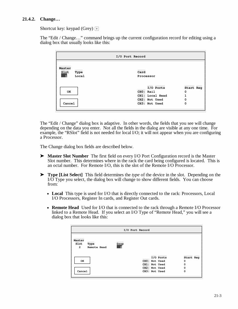
21-3
21.4.2. Change…
Shortcut key: keypad (Grey) >
The “Edit / Change…” command brings up the current configuration record for editing using a dialog box that usually looks like this:
I/O Port Record
Master Slot Type Card 1 Local Processor I/O Ports Start Reg OK CH0: Rail 0 CH1: Local Head 1 CH2: Not Used 0 Cancel CH3: Not Used 0
The “Edit / Change” dialog box is adaptive. In other words, the fields that you see will change depending on the data you enter. Not all the fields in the dialog are visible at any one time. For example, the “RSlot” field is not needed for local I/O; it will not appear when you are configuring a Processor.
The Change dialog box fields are described below.
➤ Master Slot Number The first field on every I/O Port Configuration record is the Master Slot number. This determines where in the rack the card being configured is located. This is an octal number. For Remote I/O, this is the slot of the Remote I/O Processor.
➤ Type [List Select] This field determines the type of the device in the slot. Depending on the I/O Type you select, the dialog box will change to show different fields. You can choose from:
• Local This type is used for I/O that is directly connected to the rack: Processors, Local I/O Processors, Register In cards, and Register Out cards.
• Remote Head Used for I/O that is connected to the rack through a Remote I/O Processor linked to a Remote Head. If you select an I/O Type of “Remote Head,” you will see a dialog box that looks like this:
I/O Port Record
Master Slot Type Drop 2 Remote Head 0 I/O Ports Start Reg OK CH0: Not Used 0 CH1: Not Used 0 CH2: Not Used 0 Cancel CH3: Not Used 0
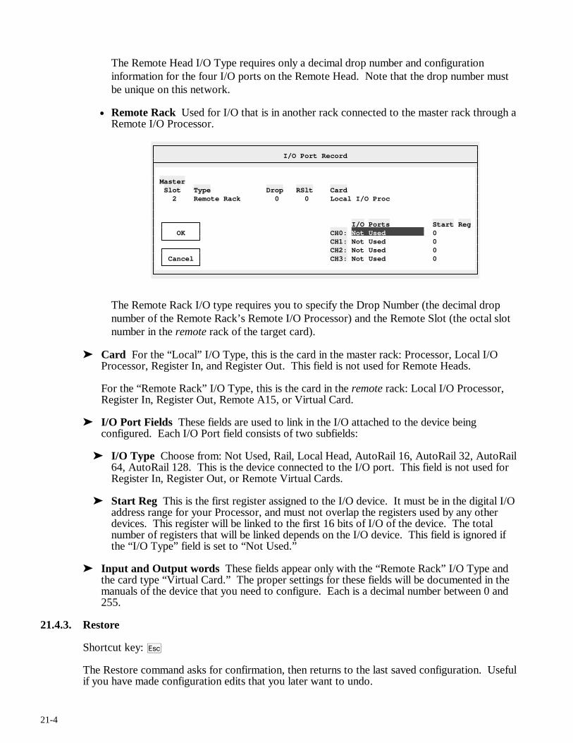
21-4
The Remote Head I/O Type requires only a decimal drop number and configuration information for the four I/O ports on the Remote Head. Note that the drop number must be unique on this network.
• Remote Rack Used for I/O that is in another rack connected to the master rack through a Remote I/O Processor.
I/O Port Record
Master Slot Type Drop RSlt Card 2 Remote Rack 0 0 Local I/O Proc I/O Ports Start Reg OK CH0: Not Used 0 CH1: Not Used 0 CH2: Not Used 0 Cancel CH3: Not Used 0
The Remote Rack I/O type requires you to specify the Drop Number (the decimal drop number of the Remote Rack’s Remote I/O Processor) and the Remote Slot (the octal slot number in the remote rack of the target card).
➤ Card For the “Local” I/O Type, this is the card in the master rack: Processor, Local I/O Processor, Register In, and Register Out. This field is not used for Remote Heads.
For the “Remote Rack” I/O Type, this is the card in the remote rack: Local I/O Processor, Register In, Register Out, Remote A15, or Virtual Card.
➤ I/O Port Fields These fields are used to link in the I/O attached to the device being configured. Each I/O Port field consists of two subfields:
➤ I/O Type Choose from: Not Used, Rail, Local Head, AutoRail 16, AutoRail 32, AutoRail 64, AutoRail 128. This is the device connected to the I/O port. This field is not used for Register In, Register Out, or Remote Virtual Cards.
➤ Start Reg This is the first register assigned to the I/O device. It must be in the digital I/O address range for your Processor, and must not overlap the registers used by any other devices. This register will be linked to the first 16 bits of I/O of the device. The total number of registers that will be linked depends on the I/O device. This field is ignored if the “I/O Type” field is set to “Not Used.”
➤ Input and Output words These fields appear only with the “Remote Rack” I/O Type and the card type “Virtual Card.” The proper settings for these fields will be documented in the manuals of the device that you need to configure. Each is a decimal number between 0 and 255.
21.4.3. Restore
Shortcut key: q
The Restore command asks for confirmation, then returns to the last saved configuration. Useful if you have made configuration edits that you later want to undo.
21-5
21.4.4. Insert Record…
Shortcut key: i
The “Insert Record…” command inserts a new “blank” record and brings it up for editing. See the previous section (“Edit / Change…”) for more information on editing configuration records.
The Insert command moves the current record and all following records down to make room for the new record. If the table is at capacity, APS will display an error and abort the command.
21.4.5. Delete Record
Shortcut key: d
The Delete Record command deletes the current configuration record. Later records will “move up” to fill the gap. You cannot delete the “END” record.
21.4.6. Print Table
After asking for confirmation, the Print Table command will send the current I/O Port Configuration report to the printer.
21.4.7. Update Table
The Update Table command is available online only. It saves the current configuration to the AutoMate Processor. This command also verifies that the configuration was written correctly and that the AutoMate did not set any configuration error flags.
If errors were detected, the relevant portions of the affected configuration records will be flashing (see above).
21.5. The Utility Menu
The Utility Menu is available throughout APS. It is used to configure printers, set communications parameters, and so forth. The Utility Menu is described in section 7.

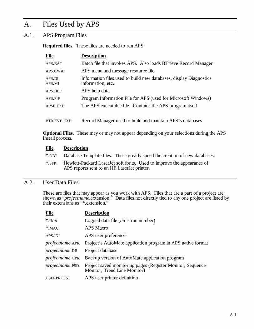
A-1
A. Files Used by APS
A.1. APS Program Files
Required files. These files are needed to run APS.
File Description
APS.BAT Batch file that invokes APS. Also loads BTrieve Record Manager
APS.CWA APS menu and message resource file
APS.DI APS.MI
Information files used to build new databases, display Diagnostics information, etc.
APS.HLP APS help data
APS.PIF Program Information File for APS (used for Microsoft Windows)
APSE.EXE The APS executable file. Contains the APS program itself
BTRIEVE.EXE Record Manager used to build and maintain APS’s databases
Optional Files. These may or may not appear depending on your selections during the APS Install process.
File Description
*.DBT Database Template files. These greatly speed the creation of new databases.
*.SFP Hewlett-Packard LaserJet soft fonts. Used to improve the appearance of APS reports sent to an HP LaserJet printer.
A.2. User Data Files
These are files that may appear as you work with APS. Files that are a part of a project are shown as “projectname.extension.” Data files not directly tied to any one project are listed by their extensions as “*.extension.”
File Description
*.Hnn Logged data file (nn is run number)
*.MAC APS Macro
APS.INI APS user preferences
projectname.APR Project’s AutoMate application program in APS native format
projectname.DB Project database
projectname.OPR Backup version of AutoMate application program
projectname.PSD Project saved monitoring pages (Register Monitor, Sequence Monitor, Trend Line Monitor)
USERPRT.INI APS user printer definition

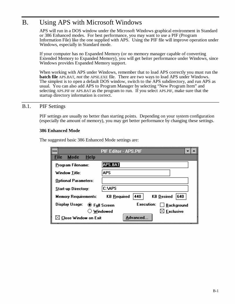
B-1
B. Using APS with Microsoft Windows APS will run in a DOS window under the Microsoft Windows graphical environment in Standard or 386 Enhanced modes. For best performance, you may want to use a PIF (Program Information File) like the one supplied with APS. Using the PIF file will improve operation under Windows, especially in Standard mode.
If your computer has no Expanded Memory (or no memory manager capable of converting Extended Memory to Expanded Memory), you will get better performance under Windows, since Windows provides Expanded Memory support.
When working with APS under Windows, remember that to load APS correctly you must run the batch file APS.BAT, not the APSE.EXE file. There are two ways to load APS under Windows. The simplest is to open a default DOS window, switch to the APS subdirectory, and run APS as usual. You can also add APS to Program Manager by selecting “New Program Item” and selecting APS.PIF or APS.BAT as the program to run. If you select APS.PIF, make sure that the startup directory information is correct.
B.1. PIF Settings
PIF settings are usually no better than starting points. Depending on your system configuration (especially the amount of memory), you may get better performance by changing these settings.
386 Enhanced Mode
The suggested basic 386 Enhanced Mode settings are:
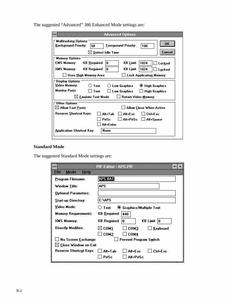
B-2
The suggested “Advanced” 386 Enhanced Mode settings are:
Standard Mode
The suggested Standard Mode settings are:
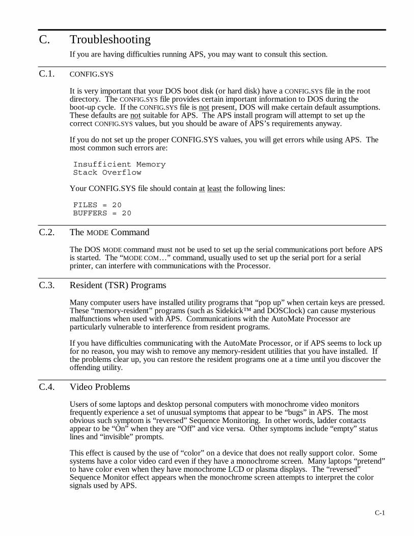
C-1
C. Troubleshooting If you are having difficulties running APS, you may want to consult this section.
C.1. CONFIG.SYS
It is very important that your DOS boot disk (or hard disk) have a CONFIG.SYS file in the root directory. The CONFIG.SYS file provides certain important information to DOS during the boot-up cycle. If the CONFIG.SYS file is not present, DOS will make certain default assumptions. These defaults are not suitable for APS. The APS install program will attempt to set up the correct CONFIG.SYS values, but you should be aware of APS’s requirements anyway.
If you do not set up the proper CONFIG.SYS values, you will get errors while using APS. The most common such errors are:
Insufficient Memory Stack Overflow
Your CONFIG.SYS file should contain at least the following lines:
FILES = 20 BUFFERS = 20
C.2. The MODE Command
The DOS MODE command must not be used to set up the serial communications port before APS is started. The “MODE COM…” command, usually used to set up the serial port for a serial printer, can interfere with communications with the Processor.
C.3. Resident (TSR) Programs
Many computer users have installed utility programs that “pop up” when certain keys are pressed. These “memory-resident” programs (such as Sidekick™ and DOSClock) can cause mysterious malfunctions when used with APS. Communications with the AutoMate Processor are particularly vulnerable to interference from resident programs.
If you have difficulties communicating with the AutoMate Processor, or if APS seems to lock up for no reason, you may wish to remove any memory-resident utilities that you have installed. If the problems clear up, you can restore the resident programs one at a time until you discover the offending utility.
C.4. Video Problems
Users of some laptops and desktop personal computers with monochrome video monitors frequently experience a set of unusual symptoms that appear to be “bugs” in APS. The most obvious such symptom is “reversed” Sequence Monitoring. In other words, ladder contacts appear to be “On” when they are “Off” and vice versa. Other symptoms include “empty” status lines and “invisible” prompts.
This effect is caused by the use of “color” on a device that does not really support color. Some systems have a color video card even if they have a monochrome screen. Many laptops “pretend” to have color even when they have monochrome LCD or plasma displays. The “reversed” Sequence Monitor effect appears when the monochrome screen attempts to interpret the color signals used by APS.
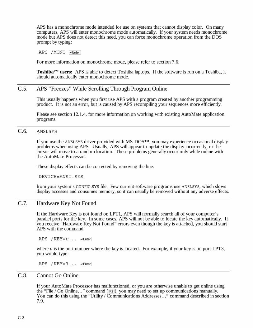
C-2
APS has a monochrome mode intended for use on systems that cannot display color. On many computers, APS will enter monochrome mode automatically. If your system needs monochrome mode but APS does not detect this need, you can force monochrome operation from the DOS prompt by typing:
APS /MONO r
For more information on monochrome mode, please refer to section 7.6.
Toshiba™ users: APS is able to detect Toshiba laptops. If the software is run on a Toshiba, it should automatically enter monochrome mode.
C.5. APS “Freezes” While Scrolling Through Program Online
This usually happens when you first use APS with a program created by another programming product. It is not an error, but is caused by APS recompiling your sequences more efficiently.
Please see section 12.1.4. for more information on working with existing AutoMate application programs.
C.6. ANSI.SYS
If you use the ANSI.SYS driver provided with MS-DOS™, you may experience occasional display problems when using APS. Usually, APS will appear to update the display incorrectly, or the cursor will move to a random location. These problems generally occur only while online with the AutoMate Processor.
These display effects can be corrected by removing the line:
DEVICE=ANSI.SYS
from your system’s CONFIG.SYS file. Few current software programs use ANSI.SYS, which slows display accesses and consumes memory, so it can usually be removed without any adverse effects.
C.7. Hardware Key Not Found
If the Hardware Key is not found on LPT1, APS will normally search all of your computer’s parallel ports for the key. In some cases, APS will not be able to locate the key automatically. If you receive “Hardware Key Not Found” errors even though the key is attached, you should start APS with the command:
APS /KEY=n … r
where n is the port number where the key is located. For example, if your key is on port LPT3, you would type:
APS /KEY=3 … r
C.8. Cannot Go Online
If your AutoMate Processor has malfunctioned, or you are otherwise unable to get online using the “File / Go Online…” command (@), you may need to set up communications manually. You can do this using the “Utility / Communications Addresses…” command described in section 7.9.

C-3
Going online in this way is called “Forcing Online” since you are connecting to the AutoMate Processor without the usual tests performed by the “File / Go Online…” command.
Note that Forcing Online will only work if the connection to the Processor is basically sound. In other words, use Force Online if the “File / Go Online…” gives a processor error, especially “Error 61.” Communications errors like “Timeout” and “Communications Checksum Error” will not be prevented by the Force Online command; these are symptoms of a fault in the connection between your computer and the AutoMate Processor.

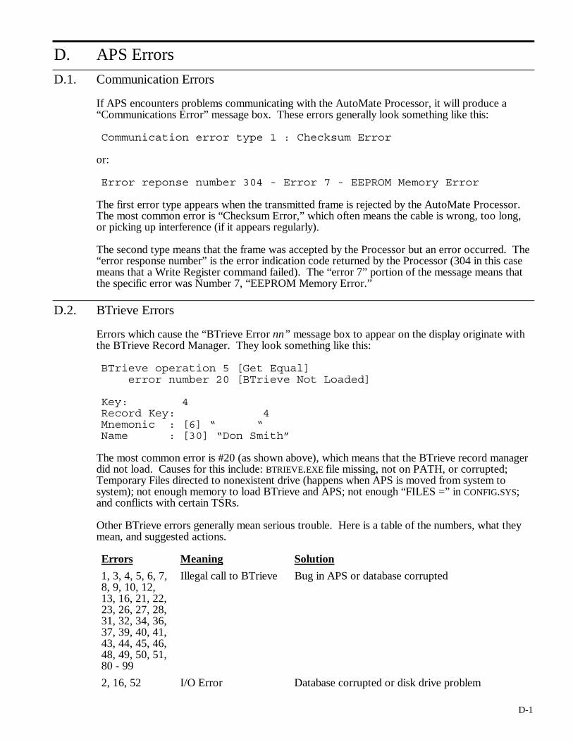
D-1
D. APS Errors
D.1. Communication Errors
If APS encounters problems communicating with the AutoMate Processor, it will produce a “Communications Error” message box. These errors generally look something like this:
Communication error type 1 : Checksum Error
or:
Error reponse number 304 - Error 7 - EEPROM Memory Error
The first error type appears when the transmitted frame is rejected by the AutoMate Processor. The most common error is “Checksum Error,” which often means the cable is wrong, too long, or picking up interference (if it appears regularly).
The second type means that the frame was accepted by the Processor but an error occurred. The “error response number” is the error indication code returned by the Processor (304 in this case means that a Write Register command failed). The “error 7” portion of the message means that the specific error was Number 7, “EEPROM Memory Error.”
D.2. BTrieve Errors
Errors which cause the “BTrieve Error nn” message box to appear on the display originate with the BTrieve Record Manager. They look something like this:
BTrieve operation 5 [Get Equal] error number 20 [BTrieve Not Loaded] Key: 4 Record Key: 4 Mnemonic : [6] “ “ Name : [30] “Don Smith”
The most common error is #20 (as shown above), which means that the BTrieve record manager did not load. Causes for this include: BTRIEVE.EXE file missing, not on PATH, or corrupted; Temporary Files directed to nonexistent drive (happens when APS is moved from system to system); not enough memory to load BTrieve and APS; not enough “FILES =” in CONFIG.SYS; and conflicts with certain TSRs.
Other BTrieve errors generally mean serious trouble. Here is a table of the numbers, what they mean, and suggested actions.
Errors Meaning Solution
1, 3, 4, 5, 6, 7, 8, 9, 10, 12, 13, 16, 21, 22, 23, 26, 27, 28, 31, 32, 34, 36, 37, 39, 40, 41, 43, 44, 45, 46, 48, 49, 50, 51, 80 - 99
Illegal call to BTrieve Bug in APS or database corrupted
2, 16, 52 I/O Error Database corrupted or disk drive problem
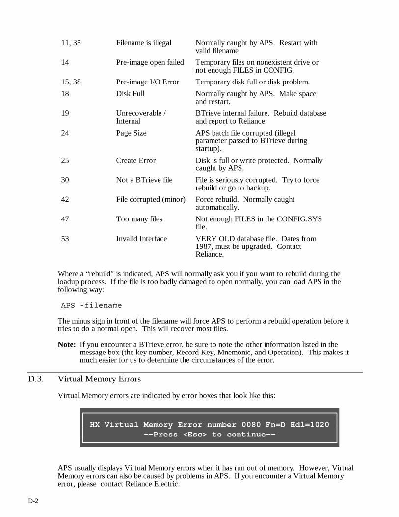
D-2
11, 35 Filename is illegal Normally caught by APS. Restart with valid filename
14 Pre-image open failed Temporary files on nonexistent drive or not enough FILES in CONFIG.
15, 38 Pre-image I/O Error Temporary disk full or disk problem.
18 Disk Full Normally caught by APS. Make space and restart.
19 Unrecoverable / Internal
BTrieve internal failure. Rebuild database and report to Reliance.
24 Page Size APS batch file corrupted (illegal parameter passed to BTrieve during startup).
25 Create Error Disk is full or write protected. Normally caught by APS.
30 Not a BTrieve file File is seriously corrupted. Try to force rebuild or go to backup.
42 File corrupted (minor) Force rebuild. Normally caught automatically.
47 Too many files Not enough FILES in the CONFIG.SYS file.
53 Invalid Interface VERY OLD database file. Dates from 1987, must be upgraded. Contact Reliance.
Where a “rebuild” is indicated, APS will normally ask you if you want to rebuild during the loadup process. If the file is too badly damaged to open normally, you can load APS in the following way:
APS -filename
The minus sign in front of the filename will force APS to perform a rebuild operation before it tries to do a normal open. This will recover most files.
Note: If you encounter a BTrieve error, be sure to note the other information listed in the message box (the key number, Record Key, Mnemonic, and Operation). This makes it much easier for us to determine the circumstances of the error.
D.3. Virtual Memory Errors
Virtual Memory errors are indicated by error boxes that look like this:
HX Virtual Memory Error number 0080 Fn=D Hdl=1020 --Press <Esc> to continue--
APS usually displays Virtual Memory errors when it has run out of memory. However, Virtual Memory errors can also be caused by problems in APS. If you encounter a Virtual Memory error, please contact Reliance Electric.

D-3
D.4. Memory Problems
If APS does not have enough available system memory, it will start to display error boxes like “Could not create xxx window.” Normally, you can still exit if APS runs out of memory. Re-entering APS will compact memory and gain you some more operating time. The only long-term solution, though, is to free up more memory for APS by unloading TSRs, logging out of networks, or purchasing Expanded Memory.

E-1
E. APS Glossary
block A group of 16 Point or Register definitions. APS always stores its Point and Register definitions in groups of 16. For example, when you edit block 26 of Point definitions, you will be editing the definitions for points 26.00 - 26.17.
boolean A field that can have only two possible values, such as “Yes” and “No.”
checksum error
A message that can appear while you are online with the AutoMate. This means that the program in your computer’s memory is not the same as the program in the AutoMate. You should use the “File / Upload (From)” or “File / Download (To)” commands to synchronize the two programs.
digital I/O description
A point definition that describes a real world digital input or output.
field A data-entry area on a dialog box or editing window.
internal relay description
A point definition that describes a digital value that has no real world connection.
line comment
A Sequence Description (1 line of 60 characters) that appears above the rung it is attached to in the Documented Ladder Listing.
line number The number of contact row counted from the first row in the program. In APS, line numbers are always marked with a greater-than sign (e.g., “>200”).
list select field
A dialog box field that can have one of several different values. Press keypad (Grey) > to choose from a list of values.
paste buffer A temporary storage area that can hold data from text fields. You can place data in this area with the “Edit / Cut” and “Edit / Copy” commands; retrieve the text with the “Edit / Paste” command.
project A group of files that make up a single APS application. A typical project includes a database file (.DB extension), an application program file (.APR extension), and certain other files depending on what APS features you use.
section One of the basic operational areas of APS found on the Select menu: Document Point / Register Descriptions; Document Sequence Descriptions; Document Title Descriptions; Edit Sequence; Sequence Monitor; Register Monitor; Trend Line; Diagnostics; History; and I/O Port Configuration.

E-2
section comment
A Sequence Description (2 lines of 60 characters) that begins a new page in the Documented Ladder Listing.
text comment
A Sequence Description (up to 1000 lines of 60 characters) that appears above the rung it is attached to in the Documented Ladder Listing.