Embed Size (px)
Citation preview
APS Storage Ring Injection Topics: Optimization and Topup
Louis Emery, Michael Borland and Vadim SajaevMay 31st 2006
2
Outline
APS operating modes Review of the APS injector Injection Optimization
– Booster extraction jitter– SR vertical emittance– SR firstturn trajectory fitting, optimization– Transfer line optics– SR dynamic aperture
Topup– Safety– Problems and requirements– Performance at APS
3
APS Operator Parameters
Operating parameters and modes determine injector requirements Presently, always operate at 100 mA
– Not all beamlines can withstand higher current– Accelerator designed for 300 mA– Have filled to 250 mA for machine studies
All operating modes now use the lowemittance lattice– Raw emittance is 2.5 nm– Effective emittance is 3.1 nm– Original APS emittance was 7.7 nm
Operating modes distinguished by fill pattern.

4
Fill Patterns
24 bunches, uniformly spaced– Supports timeresolved studies– Used ~60% of the time– Lifetime is 6 hours, so topup is required
324 bunches, uniformly spaced, and 1296 bunches– Used ~20% of the time– Lifetime is 60 and 100 hours, topup is not required– Refill every 12 hours
Hybrid mode:– Supports timeresolved studies– Used ~20% of time– One 16 mA bunch and 56, 1.5 mA bunches– Lifetime of 16 mA bunch is ~2 hours, topup
required.

5
Overall Layout of APS Injectors
Low-Energy Undulator
Test Line (LEUTL)
(undulators now removed)
325 MeV
Particle Accumulator
Ring (PAR)
2 Hz, 7 GeV Booster SynchrotronPhotocathode
gun and injector
Dual
thermionic
rf guns
Bunch
compressor
150 MeV
Up to 450 MeV
APS ring

6
Motivation of Injection Optimization
Reduce radiation damage in undulators– both Toushek scattered particles (80%) and injection loss
particles (20%)Reduce charge required by injectors in topupSR Trajectory and BTS Optics studiesSR Dynamic aperture studies

7
Booster Extraction
Stable transfer line trajectory facilitates injection into SR– requirement is 1 in hor. beam size (1.1 mm)– vertical trajectory has been very stable
Sources of error– Septum jitter– Kicker jitter– Booster momentum jitter (< ±0.04%)– Booster orbit jitter (~25 m)
Septum power supplies were primary problem– Jitter is too small to be measured directly; need beam– ±0.15% (0.1 mrad) with original supplies– Also drift due to thermal effect on resistance of coils
• supply provides a fixed voltage pulse.
8
Correction of Problems
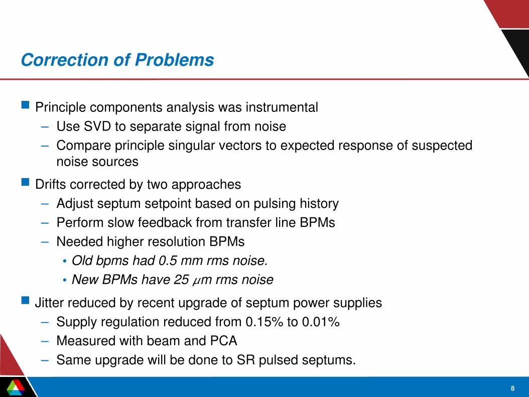
Principle components analysis was instrumental– Use SVD to separate signal from noise– Compare principle singular vectors to expected response of suspected
noise sources Drifts corrected by two approaches
– Adjust septum setpoint based on pulsing history– Perform slow feedback from transfer line BPMs– Needed higher resolution BPMs
• Old bpms had 0.5 mm rms noise.• New BPMs have 25 m rms noise
Jitter reduced by recent upgrade of septum power supplies– Supply regulation reduced from 0.15% to 0.01%– Measured with beam and PCA – Same upgrade will be done to SR pulsed septums.

9
Booster Extraction
Pair of BPMs with largest correlation due to septum jitter over last two upgrades
2001 2003 2005

10
Booster Extraction
Spectrum of singular values
Proportional to jitter amplitude
Proportional to bpm noise
11
APS Storage Ring
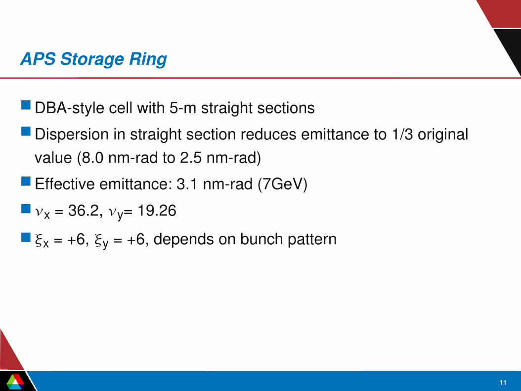
DBAstyle cell with 5m straight sectionsDispersion in straight section reduces emittance to 1/3 original
value (8.0 nmrad to 2.5 nmrad)Effective emittance: 3.1 nmrad (7GeV)x = 36.2, y= 19.26x = +6, y = +6, depends on bunch pattern

12
Machine Functions and Layout
13
Vertical Emittance
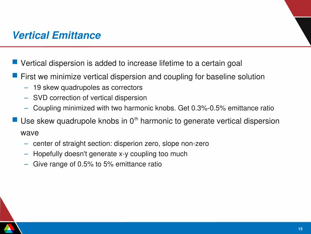
Vertical dispersion is added to increase lifetime to a certain goal First we minimize vertical dispersion and coupling for baseline solution
– 19 skew quadrupoles as correctors– SVD correction of vertical dispersion– Coupling minimized with two harmonic knobs. Get 0.3%0.5% emittance ratio
Use skew quadrupole knobs in 0 th harmonic to generate vertical dispersion wave– center of straight section: disperion zero, slope nonzero– Hopefully doesn't generate xy coupling too much– Give range of 0.5% to 5% emittance ratio

14
Vertical Dispersion 0th Harmonic

15
Sextupole Magnets
Sextupole magnet strength have increased with changes to lattice optics over the years.– dynamic aperture 710 mm, depending on optics correction
and coupling errors.Four families with 2parameter freedom to optimize lifetime,
dynamic aperture or injection bump. Individual PS's; allows lattice development with sectors of
sextupoles turned off.

16
Limiting Storage Ring Apertures
Main chamber: ±42 mm in x, ±21 mm in yVertical apertures in straight sections
– ±2.5 mm in two straight sections, four cells downstream of injection point
– ±4.0 mm typicallyHorizontal apertures in straight sections:
– 15 mm in two straight sections– 17 mm at injection septum– Much larger in positive direction (e.g. pumping slots)

17
Injection System
Four kickers located over two cells fire simultaneously~1 mrad kicks produce 16 mm at injection pointBooster beam launches into SR at about 23 mmBooster beam size is about 1.3 mm rms. Injection centroid oscillation for matched bump is about 7 mm,
but some particles in distribution oscillate for much more, say 11 mm.

18
7 mm oscillation
19
Injection Girder 3D Drawing
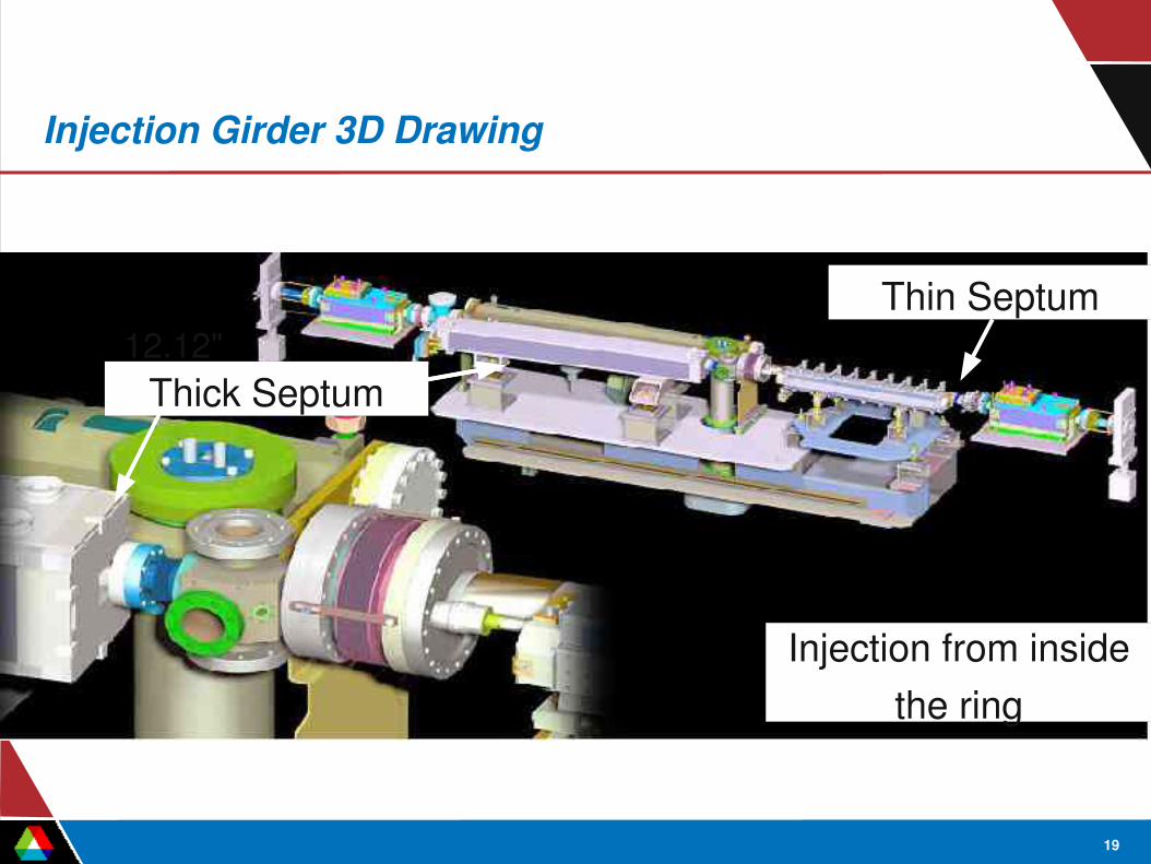
Thick Septum
Thin Septum
Injection from insidethe ring
12.12"

20
Injection Vacuum Chamber Aperture
Storage ring chamber
BTS chamber(1 cm Dia.)
Projection of septum aperture (2.3 mm)
16 mm
7 mmRegular chamber aperture
±42 mm by ±21 mm

21
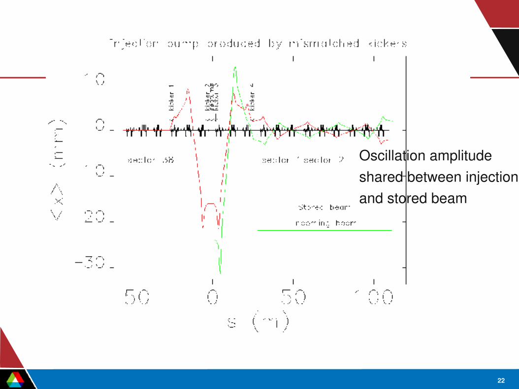
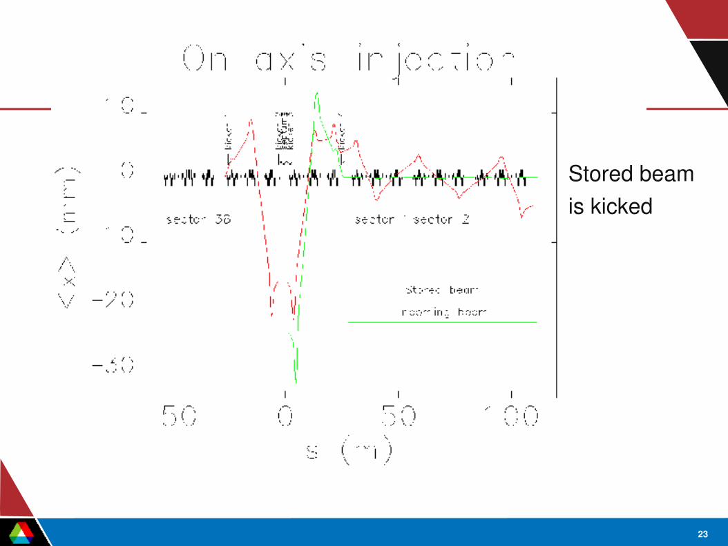
Mismatched Kicker Bump
Increasing the kick angle of last two kickers:– lowers injected beam oscillation– creates stored beam oscillation
At large enough kick, one gets onaxis injection, such as in a booster.
Optimum aperture conditions exists somewhere between matched bump and onaxis condition.
22
Oscillation amplitudeshared between injection and stored beam
23
Stored beamis kicked
24
Modeling the FirstTurn Trajectory
Collect data from turnbyturn BPMs for:– Onaxis, matched bump, optimized bump
Injection efficiency had been optimized with horizontal steering in BTS and horizontally deflecting septums using EPICS tool sddsoptimize
Match the initial condition x, x', dp in a model that correspond closest with measurement using simplex minimization

25
Firstturn Trajectory Measurement
Result for hplane may guide us to problems with septum or injection area apertures
Value for x should be around the design value of 23 mm

26
x = 23 mmx' = 0 mraddp = 0 %
x = 24.7 mmx' = 0.13 mraddp = 0.31 %

27
Comments on Fitting and Measurement
Injection oscillation for matched bump condition is then ~8.6 mm with dp=0.3%, apparently at or over the edge of the dynamic aperture.
Model doesn't fit all parts of the oscillation– Should use a fitted ring model for optics– Should use bpm readback offset for small charge condition
Momentum launching error is confirmed by BPM history over 2000 turns.

28
More Comments
Negative momentum error is a good thing, as it reduces betatron oscillation (Y.C. Chae)– works for injection from interior of ring, and positive
dispersion at injection point.New injection area (Jan 2004) have been surveyed for exact
aperture positions.Surveyed YAG crystal inserted between two septum can be
used as BPM for BTS beam. (Not used yet)
29
Conclusion on SR Trajectory
Comparison of measurements and model of injection process doesn't reveal a bad alignment.
One could plan to setup longitudinal injection with say, dp = 0.5%, and reduce the betatron oscillation somewhat.

30
Nominal BTS Optics
Nonzero dispersionout of booster
Dispersion zeroat SR injection point

31
Dispersion Measurement
Vary the timing of booster extraction along rampDo not vary any magnets in BTS lineLaunching condition at booster extraction kicker does not vary,
i.e. x=0, x'=0 for all timing stepsMeasured response of BTS bpms to timing change is a kind of
“dispersion” that has initial value of 0 at kicker
32
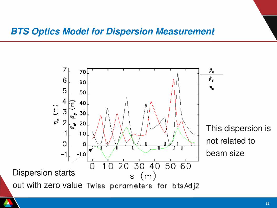
BTS Optics Model for Dispersion Measurement
Dispersion startsout with zero value
This dispersion is not related to beam size

33
Model Adjustment Based on Dispersion Measurement
Measurement agreeswith a model with 2.1% too strongquadrupoles
34
Comments on Optics Error
After correcting the error, we got better injection efficiency. Identified a bpm displaced by ~2 m. Confirmed with online
photographs during the runA corrector response measurement would give the same
result, if triedDispersion response is easier to analyze.

35
Conclusion on BTS Characterization
Obtained a good model of BTS opticsNext step is to measure beam size at septum, and check with
model– YAG crystal (for high resolution) between two septum is
available but image is not calibrated yet.

36
Dynamic Aperture
Measurement, calculation Coupling, lifetime Sextupole familiies
37
Measurements
We can only measure horizontal dynamic aperture. Vertical physical aperture is very small
We use current monitor to measure the current left after the kick (cannot distinguish between fast and slow losses)
We use singleturn beam history to calibrate the amplitude of the kick

38
Measurements
Measured dynamic aperture (an amplitude of 50% loss) is 10 mm
39
Calculations
sddscompliant elegantCalibrated model, i.e. quadrupole gradients that match the
measured opticsUse all aperture limitationsLinux cluster, sdds toolkit and tcltk scripting. All this combined
allows us to do fast and extensive calculations

40
Dynamic Aperture Calculation
Black dots are tracked particles Black symbols are surviving particles with no physical aperture Red symbols are surviving particles with physical aperture
Calculated dynamicaperture is 10.5 mm
41
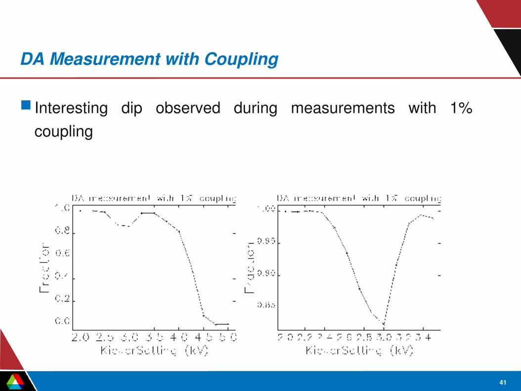
DA Measurement with Coupling
Interesting dip observed during measurements with 1% coupling

42
DA Experiment Simulation
In order to understand this effect, we simulate the kick measurement
We use 100 particles per bunch and track for 1000 turns
43
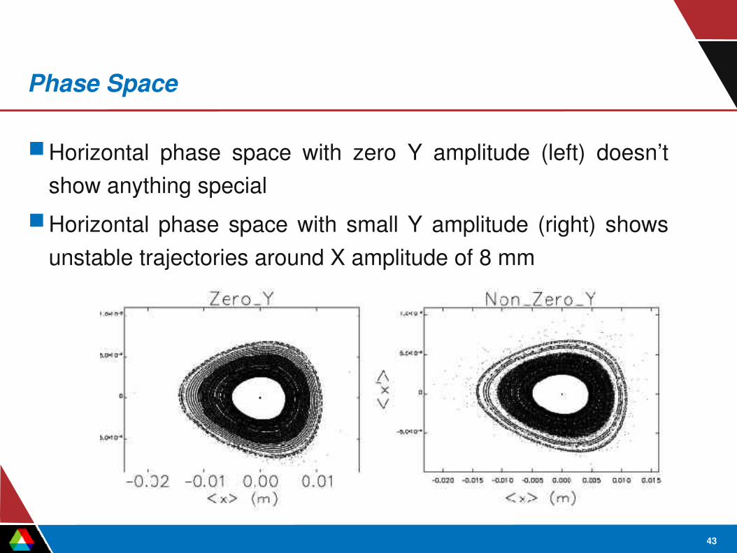
Phase Space
Horizontal phase space with zero Y amplitude (left) doesn’t show anything special
Horizontal phase space with small Y amplitude (right) shows unstable trajectories around X amplitude of 8 mm

44
Nonlinear Detuning
Tracking shows that vertical nonlinear detuning with horizontal amplitude causes vertical tune to cross integer resonance νy=19
Due to fast decoherence, it is difficult to directly confirm this in experiment
MIArefined measurements were used by C.X. Wang (ANL) to calculate the detuning using decoherence rate some time ago – they were in correspondence with simulations

45
Lifetime and Topup
Topup does not remove lifetime problemMinimum possible lifetime is defined by injection charge and
topup intervalFor APS the maximum injection charge is 3 nQ and injection
interval is 2 minutes – this gives the lifetime limit of about 5 hours
To maintain lifetime of 6 hours in the lowemittance lattice at 100mA in 24 singlets, we had to run with 2.8% coupling for some time (pre2004)
46
Redistributing Sextupole Family Strengths for Lifetime Increase
APS has 4 families of sextupolesStrengths of sextupole families came from earlier high
emittance latticeExperimental scan to increase lifetime was not successfulDynamic aperture optimization using tracking didn’t give big
benefit within limits of power suppliesA new script to perform standardized nonlinear calculation for
different lattices was written for different purpose. That script helped us to find a simple way to improve the lifetime

47
Lifetime Increase
We found that with our present sextupole scheme the working point hits 19.5 at dp/p=0.016
By increasing S2 family (S3 and S4 were used to keep chromaticity) we increased that to dp/p=0.019
This change combined with small tune change and small optimization of RF voltage allowed us to lower our coupling to 1%

48
Chromaticity of Operating Modes
0.0169.09.58 16 mA
0.0225.03.0324 bunches
0.0196.06.024 singlets
dp/pνy=19.5 limit
Chrom YChrom X

49
Dynamic Aperture for Different Modes

50
Conclusion for Dynamic Aperture
In general, we have a good correspondence between dynamic aperture measurements and simulations
Tracking with calibrated model and with real aperture limitations is important
Fast calculations are useful, they allow us to quickly test many different ideas. Fast calculations are achieved by combining parallel processing with sdds toolkit and tcl/tk scripting

51
TopUp
Topup is a recentlydeveloped method of storage ring operation– Normally, stored beam decays and is replenished every 6 to 12 hours– In topup, we replenish beam every few minutes.

52
TopUp Issues
Safety concernsSafety interlock optionsSafety analysis for APSRegulation goals and limitationsInjection transientsRadiation concernsAutomationBenefits and costs.

53
Why Are Light Source Safe?
Photon beamlines of necessity diverge from the design electron beam path due to dipole magnets
If a dipole shorts, field loss is gradual– Stored beam is lost before it “escapes” down a photon beamline– Only lose one store, not continuous beam
Topup or filling with shutters open is different:– Injected beam not on the stored beam orbit– Fast pulsed magnets are being used– Injected beam might have the wrong energy– Injection provides potentially continuous source of beam.

54
Schematic of Beamline Geometry
ID
straightID
straight
Multipoles
AM dipole BM dipole
Crotch and wedge
absorbers
ID/AM
x-ray
beamline
Photon
aperture
Potential electron-beam
path with shorted dipole
BM beamline

55
APS TopUp Safety Approach
We considered it inadequate to rely on radiation monitors alone– They can't be placed everywhere
We postulated that extraction of injected beam through a photon port is impossible if stored beam exists– If true, safety can be assured by an interlock that disables
injection when there are shutters open but no stored beam– If false, then this approach is flawed and a “topup accident”
could occur.

56
TopUp Accident
We must determine if two suchtrajectories are possible undersome circumstances.
Injected beam
Storedbeam
Location and size of aperturesimportant in determining if anaccident is possible.
57
Alternative Approaches to Topup
Place magnetic field sensors in the dipoles and interlock them to the injector– Advantage: very direct– Problems
• In principle, must have a sensor in every dipole• May be expensive and unreliable for large ring
Interlock the injector to the voltage and current from the dipole supply– Advantage: potentially very simple– Problems:
• Difficult to detect a partially shorted coil in a large ring• Possibility of spurious trips and downtime.

58
Alternative Approaches to Topup
Place permanent magnets on each photon beamline to deflect electrons into an aperture– Advantage: very direct, passive– Problems:
• May be costly for large rings• Could be challenging if photon beam pipe is large in diameter• Must ensure that devices are not tampered with• Must periodically check field in each device
Don't worry, since an accident is very unlikely– US Department of Energy not likely to accept this!

59
More Details of APS Approach to TopUp Safety
Interlock is very simple and reliable– Two beam position monitors (BPMs) are used as detectors– An independent circuit monitors each BPM – Fail safe: if current is not detected, injection cannot occur with shutters open
Ring apertures are important:– We maintain topupspecific drawings showing apertures for all sector
configurations– We verify the position of the chamber relative to all magnets using “go/nogo
gauges” every shutdown (3 month interval)– We measure apertures in any photon beamline where a change is made
A signoff process is in place to ensure compliance Topup tracking is complex and timeconsuming.

60
TopUp Safety Simulation Concept
At minimum, an accident requires a fully or partiallyshorted dipole in the location of a photon beamline
For a fullyshorted dipole– injected beam will exit the photon port, but– stored beam very unlikely to survive.
For an unshorted dipole– stored beam can survive, but– injected beam very unlikely to exit photon port.
Is there some degree of shorting that simultaneously allows – stored beam and – injected beam down a photon port?
Simulations are used to explore many possibilities.
61
TopUp Safety Simulation Method
We devised scenarios that had a good chance of causing an accident
At minimum, a dipole is fully or partiallyshorted In addition, we look at effect of
– Strong corrector magnet– Misaligned quadrupole or sextupole
Two types of simulations are needed– Determine if closed orbit is inside the vacuum chamber– Determine if there is a path from the upstream ID straight section
to the exit of the photon beamline.

62
Why Corrector Strength Matters
A sufficiently strong corrector aftera partially-shorted dipole could correctthe stored beam orbit.
Injected beam
Storedbeam ondistortedorbit
Partiallyshorted dipole
Strongcorrector
Could get a similar effect from adisplaced quadrupole or sextupole.

63
Backtracking Concept
Acceptance-fillingphase space
Rays escapingsector for fullyshorted dipole
Rays terminateinside dipole ifdipole unshorted
An efficient way to determine ifinjected beam can escape is back-tracking from the photon beamlineinto the accelerator.
64
Basic Formula for topUp (Uniform Fill)
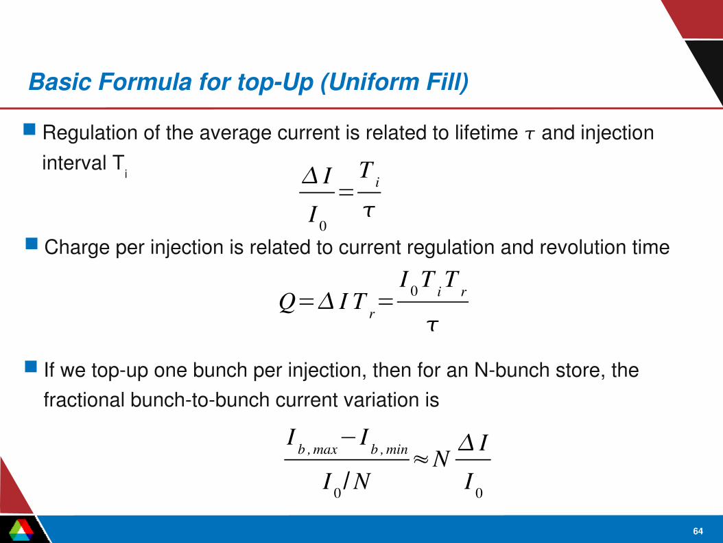
Regulation of the average current is related to lifetime and injection interval Ti I
I 0
=T i
Charge per injection is related to current regulation and revolution time
Q= I T r=I 0 T i T r
If we topup one bunch per injection, then for an Nbunch store, the fractional bunchtobunch current variation is
I b , max−I b , min
I 0 /N≈N I
I 0

65
Examples
Originally we thought about 0.01 % regulation at 100 mA– At this level, users could ignore current variation– Lifetime of 6 hours means injecting every 2 seconds– Injected charge would be 40 pC/shot, too small for our diagnostics– Users wouldn't accept this because of emittance disruption
How about 0.1% regulation?– Inject every 20 seconds– 0.4 nC/shot is acceptable for diagnostics
The bottom line– Users specified 2 minute interval as the minimum– Later, we we permitted to use 1 minute for special mode.

66
APS TopUp Fill Patterns
24 bunch– 6 hour lifetime (or better)– 2 minute injection interval– 0.6% regulation– 2.2 nC/shot– 14% bunchtobunch variation
Hybrid mode (16 mA bunch plus 56, 1.5mA bunches)– ~2 hour lifetime for 16 mA bunch– ~9 hour lifetime for other bunches– 60 second injection interval– 75% of topup shots go to 16 mA bunch– 3 to 6% variation observed in 16 mA bunch– ~40% bunchtobunch variation among 56 bunches.

67
Injection Transients
Emittance increase of stored beam due to– Betatron oscillation, which damps in 30 ms– Focusing perturbation due to sextupoles inside bump (minor)– Beam average is much less than that of bunch in injection bucket
Perturbation of global orbit due to septum leakage field– If uncorrected, produces a ~200 m orbit lasting about 25 ms– Corrected to level of normal beam motion ( 17 m) under ambient
conditions (i.e. orbit feedback turned off) Global electronic gating signal given to users to “blank” out experimental
data– Apparently not used as the transient does not affect experiments.
68
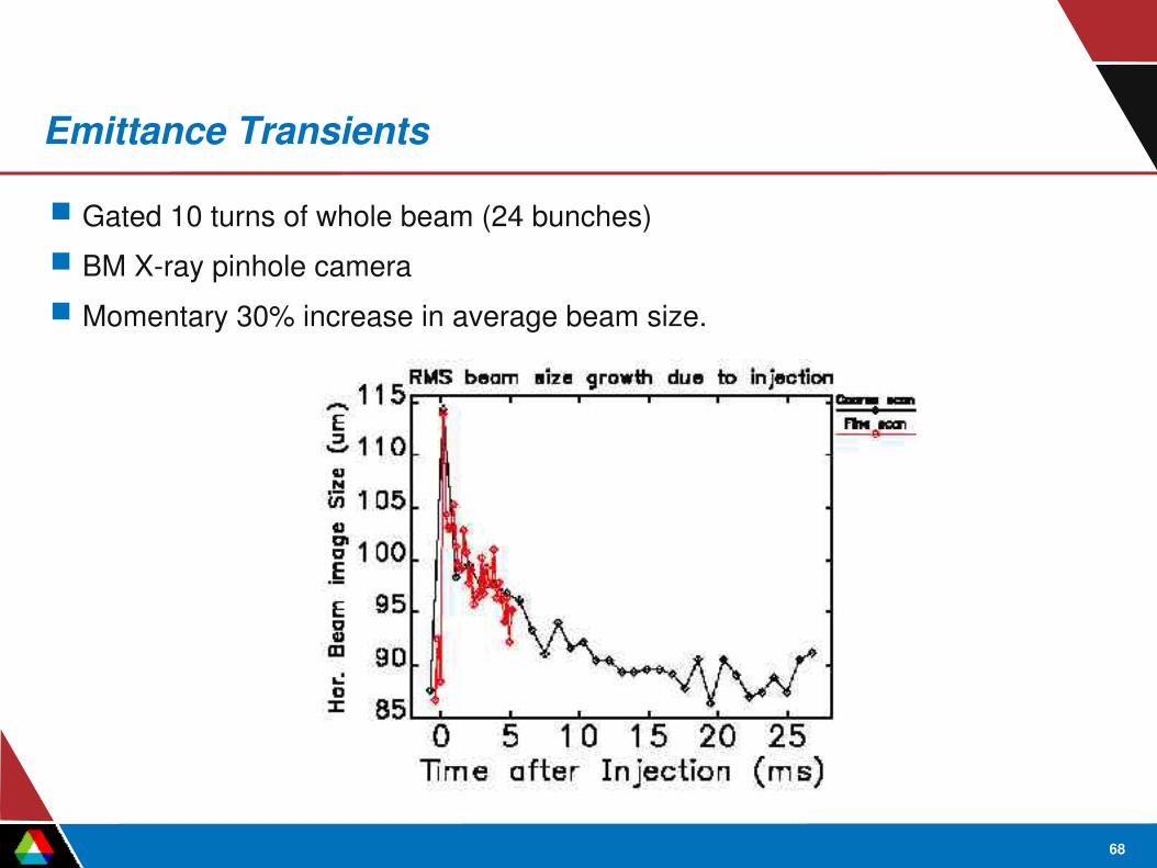
Emittance Transients
Gated 10 turns of whole beam (24 bunches) BM Xray pinhole camera Momentary 30% increase in average beam size.
69
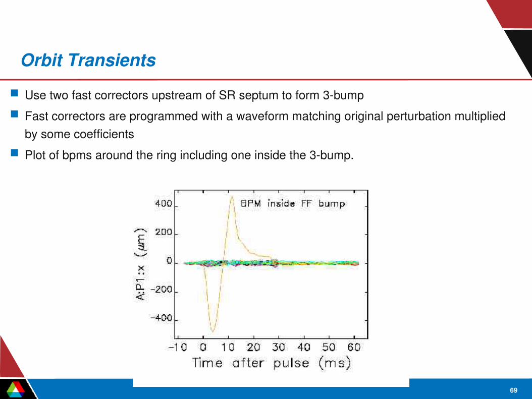
Orbit Transients Use two fast correctors upstream of SR septum to form 3bump Fast correctors are programmed with a waveform matching original perturbation multiplied
by some coefficients Plot of bpms around the ring including one inside the 3bump.

70
Radiation Issues
Topup is important because it lets us compensate for short lifetime– Lowemittance lattice– Unusual fill patterns
Short lifetime necessitates more radiation Radiation outside shield wall may be elevated
– We have radiation monitors in each sector– These may not respond even if we lost every topup shot given the long
interval• Operators monitor injection efficiency• Surveys and use of TLDs has revealed no issues
Increased radiation damage to intunnel equipment is seen.

71
Radiation Damage
Principal issue is damage to smallgap insertion devices These are close to the injection point
– Damage took only a few weeks to manifest itself– Device tapering was required during the run to restore performance– Devices required frequent retuning (6 months)
We discovered that most of the damage is Touschekscattered particles– Smallgap chambers have ring's narrowest horizontal aperture– Can be remedied with properly positioned scrapers (underway)
One smallgap device was removed (not needed) The other will be replaced with a more radhard material.

72
Automation
Countdown timers in IOC with different offsets to trigger various processes in order: start injectors, start calculations, start checking of alarms– warm up booster pulsed septums– trigger booster extraction kicker at last possible moment– script determines which bunch to inject into– monitor status of SR injection kickers with alarm handler– automatically check PAR compression and cleaning status just
before injecting Possible to inject more than one bunch at 2 Hz repetition, but users
don't want that.

73
TopUp Performance
Tune up injector to deliver more charge than needed– Ring current gradually increases, resulting in a skipped injection– Provides overhead in case of occasional problems
Typically regulate ring current to better than ±0.5% Injector reliability and availability is very high:
– 5000 hour user operation in FY2005– 98.8% availability for FY2005.
4 days of continuous top-up
detailed time-history example

74
Benefits
Users report much better xray stability– Heatload on xray optics is nearly constant– Some users are unwilling to come during nontopup periods
Originally, we expected improved electron beam stability– This wasn't seen when we started running topup– The monopulse receiver (Mp) bpms suffer from HOM around 352 MHz center
filter frequency. The HOM spectrum depends on the bunch pattern nonuniformity which changes constantly during topup
– Three improvements since then:• Added many narrowband (Nb) bpms near the light source points• The effect on the Mp bpms is much reduced by BPM “cogging”• Use of dipole ID source Xray bpms in DC orbit correction.
75
Costs
Injector is use most of the time– Lack of operator training time
• Training periods only every six weeks during 324 or 1296bunch modes
– Limited time for injector machine physics, e.g.,• Software development• CSR studies• LEUTL
Injector failures now may result in facility downtime– Beam decays rapidly if injector is unavailable– Previously, we could repair injector between fills.

76
Conclusion on TopUp
Topup used for ~80% of APS operations– Safety method relies on two simple storedcurrent
detectors– Extensive topup tracking needed to validate this
approach– Xray stability is greatly improved.