Embed Size (px)
Citation preview
Aprisa SRProduct options
2 © 2011 4RF | Confidential
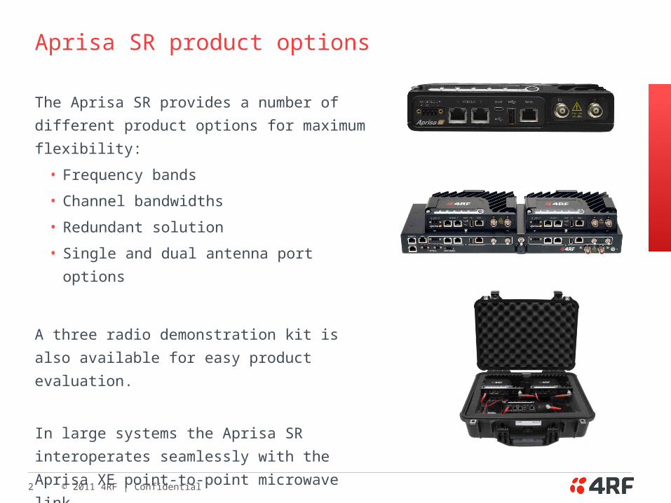
Aprisa SR product options
The Aprisa SR provides a number of different
product options for maximum flexibility:
• Frequency bands
• Channel bandwidths
• Redundant solution
• Single and dual antenna port options
A three radio demonstration kit is also available for
easy product evaluation.
In large systems the Aprisa SR interoperates
seamlessly with the Aprisa XE point-to-point
microwave link.
3 © 2011 4RF | Confidential
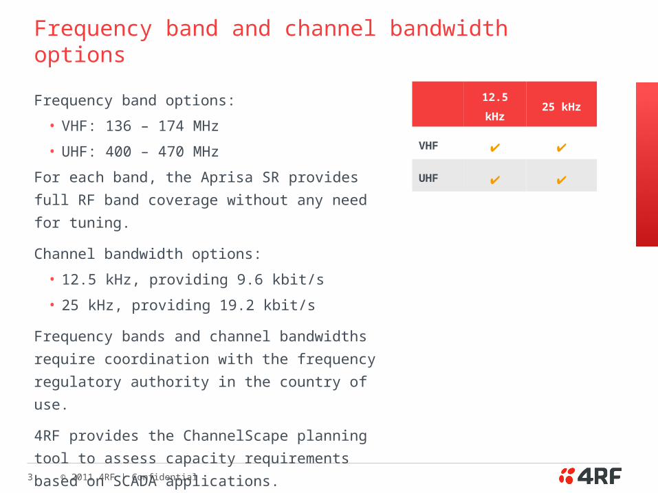
Frequency band and channel bandwidth options
Frequency band options:
• VHF: 136 – 174 MHz
• UHF: 400 – 470 MHz
For each band, the Aprisa SR provides full RF band
coverage without any need for tuning.
Channel bandwidth options:
• 12.5 kHz, providing 9.6 kbit/s
• 25 kHz, providing 19.2 kbit/s
Frequency bands and channel bandwidths require
coordination with the frequency regulatory authority in
the country of use.
4RF provides the ChannelScape planning tool to
assess capacity requirements based on SCADA
applications.
12.5 kHz 25 kHz
VHF ✔ ✔
UHF ✔ ✔
4 © 2011 4RF | Confidential
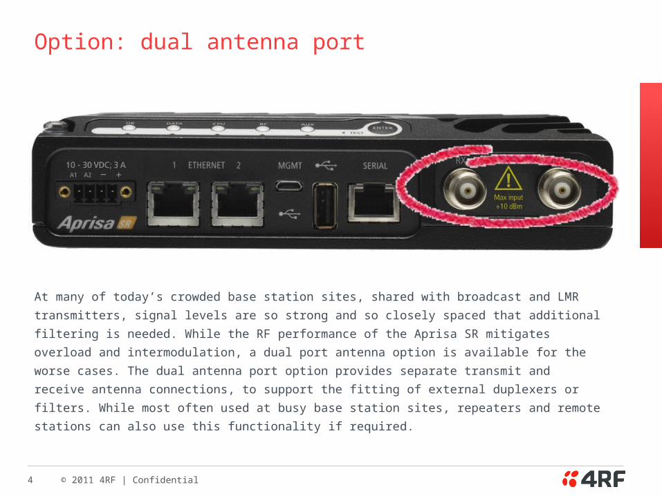
Option: dual antenna port
At many of today’s crowded base station sites, shared with broadcast and LMR
transmitters, signal levels are so strong and so closely spaced that additional filtering is
needed. While the RF performance of the Aprisa SR mitigates overload and
intermodulation, a dual port antenna option is available for the worse cases. The dual
antenna port option provides separate transmit and receive antenna connections, to
support the fitting of external duplexers or filters. While most often used at busy base
station sites, repeaters and remote stations can also use this functionality if required.
5 © 2011 4RF | Confidential
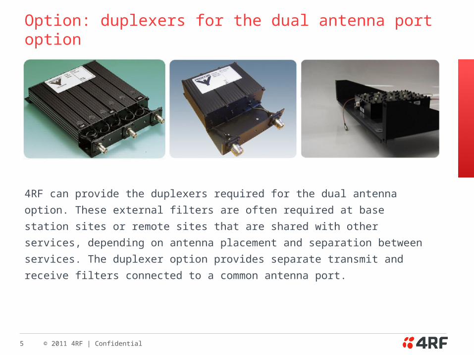
Option: duplexers for the dual antenna port option
4RF can provide the duplexers required for the dual antenna option. These external
filters are often required at base station sites or remote sites that are shared with other
services, depending on antenna placement and separation between services. The
duplexer option provides separate transmit and receive filters connected to a common
antenna port.
6 © 2011 4RF | Confidential
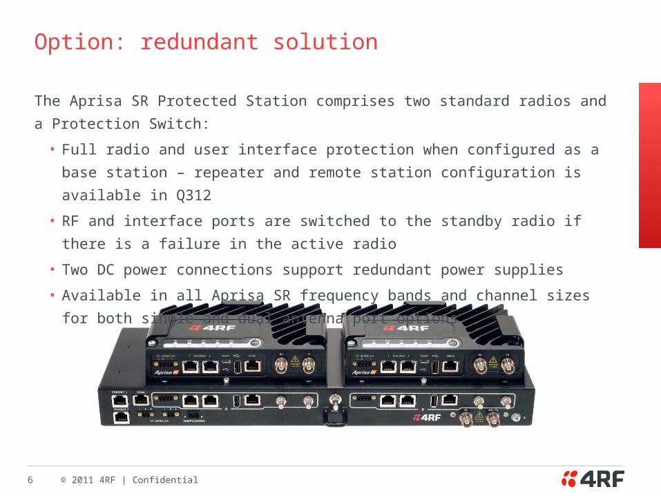
Option: redundant solution
The Aprisa SR Protected Station comprises two standard radios and a Protection Switch:
• Full radio and user interface protection when configured as a base station – repeater
and remote station configuration is available in Q312
• RF and interface ports are switched to the standby radio if there is a failure in the
active radio
• Two DC power connections support redundant power supplies
• Available in all Aprisa SR frequency bands and channel sizes for both single and dual
antenna port options
7 © 2011 4RF | Confidential
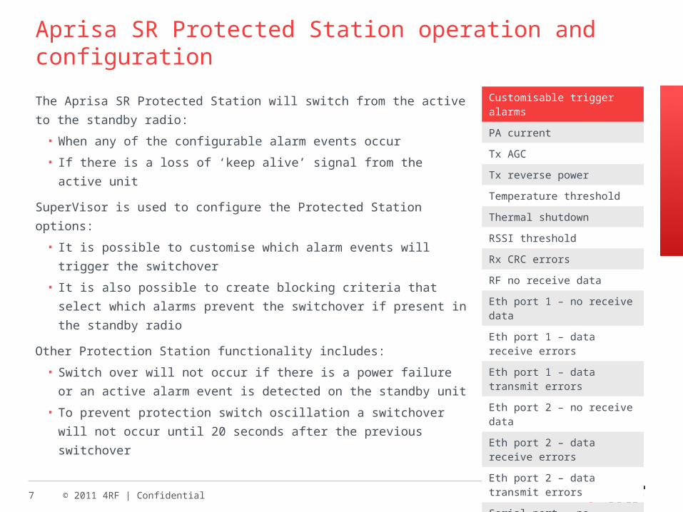
Aprisa SR Protected Station operation and configuration
The Aprisa SR Protected Station will switch from the active to
the standby radio:
• When any of the configurable alarm events occur
• If there is a loss of ‘keep alive’ signal from the active unit
SuperVisor is used to configure the Protected Station options:
• It is possible to customise which alarm events will trigger
the switchover
• It is also possible to create blocking criteria that select
which alarms prevent the switchover if present in the
standby radio
Other Protection Station functionality includes:
• Switch over will not occur if there is a power failure or an
active alarm event is detected on the standby unit
• To prevent protection switch oscillation a switchover will not
occur until 20 seconds after the previous switchover
Customisable trigger alarms
PA current
Tx AGC
Tx reverse power
Temperature threshold
Thermal shutdown
RSSI threshold
Rx CRC errors
RF no receive data
Eth port 1 – no receive data
Eth port 1 – data receive errors
Eth port 1 – data transmit errors
Eth port 2 – no receive data
Eth port 2 – data receive errors
Eth port 2 – data transmit errors
Serial port – no receive data
Serial port – data receive errors
Component failure
Calibration failure
Configuration not supported
8 © 2011 4RF | Confidential
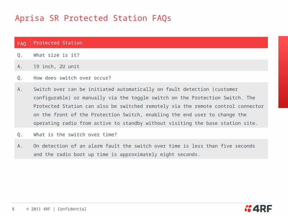
Aprisa SR Protected Station FAQs
FAQ Protected Station
Q. What size is it?
A. 19 inch, 2U unit
Q. How does switch over occur?
A. Switch over can be initiated automatically on fault detection (customer configurable) or manually via the
toggle switch on the Protection Switch. The Protected Station can also be switched remotely via the remote
control connector on the front of the Protection Switch, enabling the end user to change the operating radio
from active to standby without visiting the base station site.
Q. What is the switch over time?
A. On detection of an alarm fault the switch over time is less than five seconds and the radio boot up time is
approximately eight seconds.
9 © 2011 4RF | Confidential
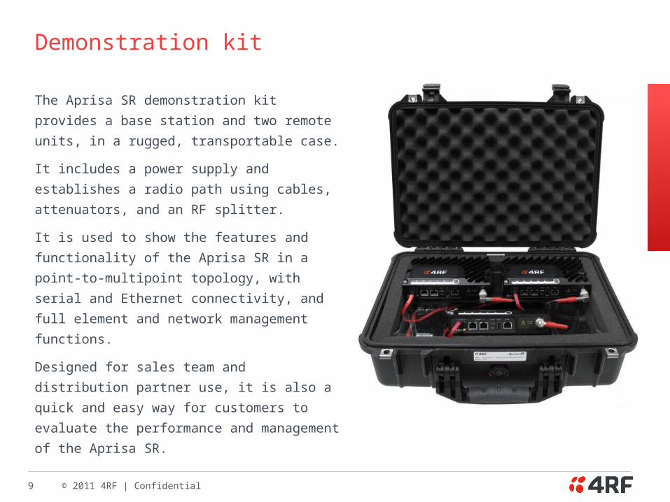
Demonstration kit
The Aprisa SR demonstration kit provides a
base station and two remote units, in a rugged,
transportable case.
It includes a power supply and establishes a
radio path using cables, attenuators, and an
RF splitter.
It is used to show the features and functionality
of the Aprisa SR in a point-to-multipoint
topology, with serial and Ethernet connectivity,
and full element and network management
functions.
Designed for sales team and distribution
partner use, it is also a quick and easy way for
customers to evaluate the performance and
management of the Aprisa SR.
10 © 2011 4RF | Confidential
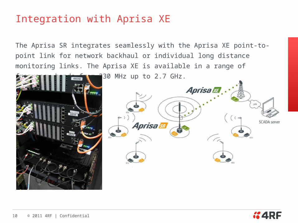
Integration with Aprisa XE
The Aprisa SR integrates seamlessly with the Aprisa XE point-to-point link for network
backhaul or individual long distance monitoring links. The Aprisa XE is available in a
range of frequency bands from 330 MHz up to 2.7 GHz.


![Aprisa SR Product Roadmap [COMPANY INTERNAL] May 2012](https://img.pdfslide.us/doc/110x75/56649e375503460f94b27ff9/aprisa-sr-product-roadmap-company-internal-may-2012.jpg)


![Aprisa XE Description[1]](https://img.pdfslide.us/doc/110x75/577d23431a28ab4e1e995d9b/aprisa-xe-description1.jpg)