Embed Size (px)
Citation preview

1
Model 5000 Electronic Air CleanerInstallation Instructions
WARNING
120 Volts may cause serious injury from electrical shock. Disconnect power to the furnace/air handler before starting installation. Leave power disconnected until installation is completed.
Arcing in electrical components may cause an explosion. Do not install unit where explosive gasses will be present.
Sharp edges may cause injury from cuts. Use care when cutting and handling sheet metal.
To reduce the risk of electrical shock, this equipment has a grounding-type (three prong) plug. This plug will fit only into a grounding-type power outlet. If the plug does not fit into the outlet, contact qualified personnel to install the proper outlet. Do not alter this plug in any way.
To reduce the risk of electrical shock, locate product so that the power cord can be plugged into an electrical outlet without the use of an extension cord.
CAUTION
To prevent component failure, do not install the air cleaner on the warm air supply or in an area where the temperature may exceed 140°F. This may include areas above heat exchangers in downflow furnaces or above exhaust flues in lowboy furnace cold air returns.
The air cleaner must be installed where the ambient air temperature remains between 32°F and 140°F [0°C and 60°C].
Installation must conform to all applicable codes.
Do not install an atomizing humidifier upstream of the air cleaner. Water or mist will cause power supply to shut down.
Do not plug the air cleaner into an outlet that is always live. The outlet must only be live when the furnace/air handler blower is operating. Failure to properly wire the outlet can result in excessive ozone production.
Read the safety and installation instructions carefully. They will help ensure a correct and SAFE installation of the Aprilaire® Electronic Air Cleaner.
SAFETY INSTRUCTIONS
Safety Instructions. . . . . . . . . . . . . . . . . . . . . . . . . . . . . . . . . . . . . . . . . . . . . . . . . . . . . . . . . . . . . . . . . . . . . . . . . . . . . . . . . . . . . . . . . . 1
Specifications. . . . . . . . . . . . . . . . . . . . . . . . . . . . . . . . . . . . . . . . . . . . . . . . . . . . . . . . . . . . . . . . . . . . . . . . . . . . . . . . . . . . . . . . . . . . . . 2
Dimensions. . . . . . . . . . . . . . . . . . . . . . . . . . . . . . . . . . . . . . . . . . . . . . . . . . . . . . . . . . . . . . . . . . . . . . . . . . . . . . . . . . . . . . . . . . . . . . . . 2
Components . . . . . . . . . . . . . . . . . . . . . . . . . . . . . . . . . . . . . . . . . . . . . . . . . . . . . . . . . . . . . . . . . . . . . . . . . . . . . . . . . . . . . . . . . . . . . . . 3
Locating the Air Cleaner . . . . . . . . . . . . . . . . . . . . . . . . . . . . . . . . . . . . . . . . . . . . . . . . . . . . . . . . . . . . . . . . . . . . . . . . . . . . . . . . . . . . . 4
Installing the Outer Housing and Inner Housing Assembly . . . . . . . . . . . . . . . . . . . . . . . . . . . . . . . . . . . . . . . . . . . . . . . . . . . . . . . . . . . . 5
Wiring and Startup . . . . . . . . . . . . . . . . . . . . . . . . . . . . . . . . . . . . . . . . . . . . . . . . . . . . . . . . . . . . . . . . . . . . . . . . . . . . . . . . . . . . . . . . . 6
Install the LED Base. . . . . . . . . . . . . . . . . . . . . . . . . . . . . . . . . . . . . . . . . . . . . . . . . . . . . . . . . . . . . . . . . . . . . . . . . . . . . . . . . . . . . . . . . 8
Install the Air Cleaner Control. . . . . . . . . . . . . . . . . . . . . . . . . . . . . . . . . . . . . . . . . . . . . . . . . . . . . . . . . . . . . . . . . . . . . . . . . . . . . . . . . 8
Troubleshooting Guide. . . . . . . . . . . . . . . . . . . . . . . . . . . . . . . . . . . . . . . . . . . . . . . . . . . . . . . . . . . . . . . . . . . . . . . . . . . . . . . . . . . . . . 14
Maintenance Recommendations. . . . . . . . . . . . . . . . . . . . . . . . . . . . . . . . . . . . . . . . . . . . . . . . . . . . . . . . . . . . . . . . . . . . . . . . . . . . . . 15
Applications with a Humidifier . . . . . . . . . . . . . . . . . . . . . . . . . . . . . . . . . . . . . . . . . . . . . . . . . . . . . . . . . . . . . . . . . . . . . . . . . . . . . . . 16
TABLE OF CONTENTS

2
FIGURE 1 – Dimensions of the Model 5000 Electronic Air Cleaner
© Research Products Corporation 2008
31" with Door28-1/8" without Door 12"24-5/8"23-7/8"
15-1/2"17-3/4"21"
19-5/8"
90-1346
SPECIFICATIONS
TABLE 1 – Initial Airflow Resistance (inches w.c.)
ModelAirflow (CFM)
1000 1200 1400 1600 1800 20005000 .10 .14 .17 .21 .25 .29
Electrical – Voltage: Door: 120 VAC ± 15% @ 50/60 Hz Control: 18-30 VACElectrical – Current /Power: Door: Consumes less than 50 watts with high voltage active. Control: 2A maximum low-voltage current for fan control
0.3-0.4 µm Particle Filtration Efficiency @ 347 fpm: 94%Replacement Media: Model 501 Airflow Capacity: up to 2000 CFM maximum
Max. Equipment Weight: Cabinet will support 400 lb. static loadAir Cleaner and LED Base Operating Environment: Temperature: 32°F – 140°F Humidity: 0-90% non-condensingAir Cleaner Control Operating Environment: Temperature: 20°F – 120°F Humidity: 0-90% non-condensing
Do not wire the Control to EAC terminals of HVAC system. These terminals are 120 Volts and will damage the Air Cleaner Control.
CAUTION
DIMENSIONS
3
Pleat Spacers (6)
#501 Media
Outer Housingwith Door Retainers
Inner Housing Assembly
InnerHousing
Ionizer Frame
Control Electrode
Power Pack/DoorAssembly
On/OffSwitch
Latches
90-1152
FIGURE 2 – Model 5000 Electronic Air Cleaner
COMPONENTS
Control & LED Base
4
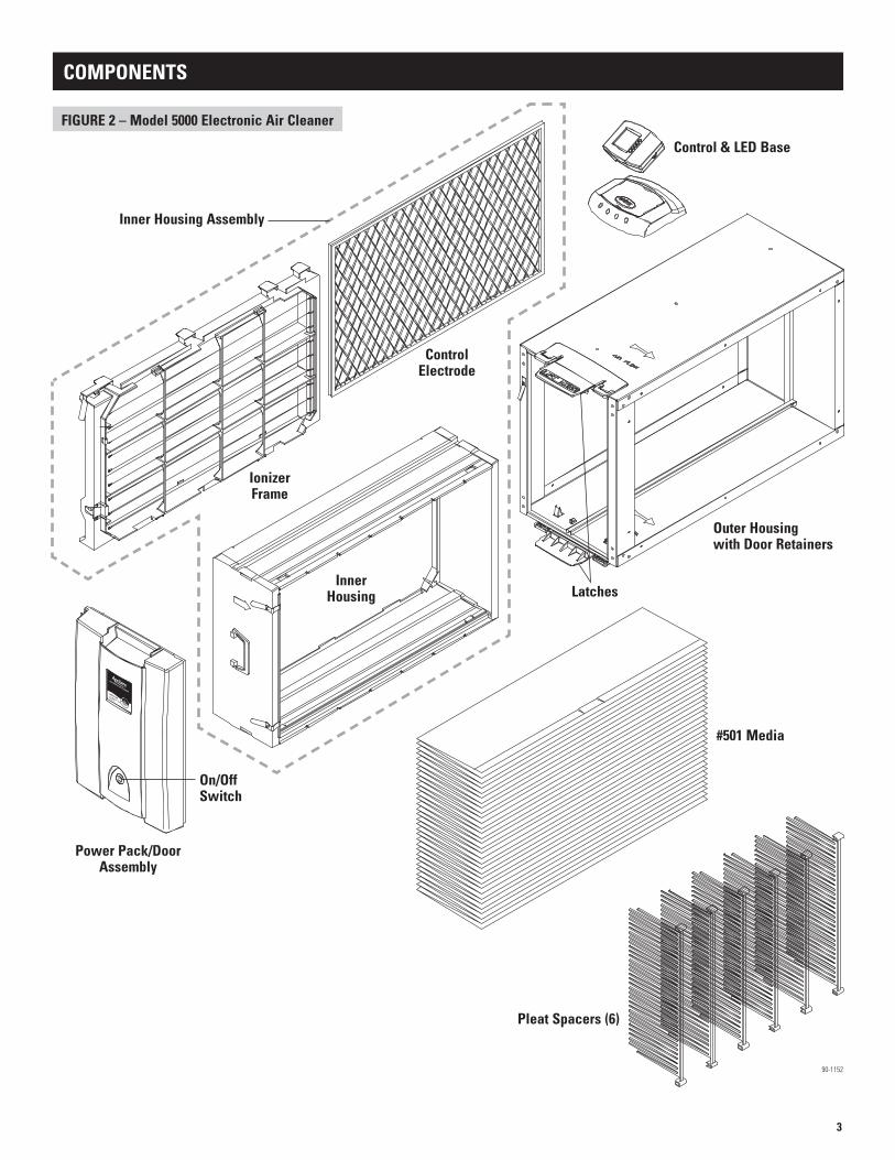
LOCATING THE AIR CLEANER
Airflow
Airflow
Airflow Airflow
30 max.
45 max.
Minimize Angles Where Possible
Airflow
Plenum Box
Airflow
Plenum Box
Size Plenum Box to fit outer housing without door: 17 3/4” x 28 1/8”
See Figure 2 for complete dimensions
FIGURE 8 FIGURE 9
FIGURE 6 FIGURE 7
FIGURE 4 FIGURE 5
Note: Air Cleaner outer housing can support up to 400 lbs.
Left side install shown
The Model 5000 can be installed in a variety of ways. The figures below show some of the possibilities.
The air cleaner may be installed on the left or right side of the air handler. If installed on the right, the ON/OFF switch will be on top and the nameplate will be on the bottom. Remove the nameplate and rotate it 180° to read properly.
FIGURE 3 – Clearance for Inner Housing Removal
18"
12"29"
It is important to leave enough room to remove and re-install the Inner Housing.
Allow Clearance for Removal of Inner Housing for Filter Replacement.
Bottom Return in upflow “Highboy” installation.(Figure 4)
Inline in duct, horizontal or vertical installation.(Figure 5)
Side Return in upflow “Highboy” installation.(Figures 6 & 7)
Compact Side Return in upflow “Highboy” installation (Figures 8 & 9). Either of the methods shown in Figures 6 and 7 will result in a narrower “footprint”, creating better clearance in tight mounting applications.
* Leave 4-1/2” above LED Base to allow for installation of Air Cleaner Control.
90-1347
90-1158A 90-1159A
90-1160A 90-1161A
90-1162A
90-1163A
Left side install shown

5
1. Turn the system OFF at the thermostat by changing the mode selector to OFF – this may be a switch or a pushbutton, depending on the type of thermostat.
2. Disconnect power service to the furnace or air handler.
3. Remove air cleaner power pack / door assembly and pull inner assembly out of the outer housing.
4. Remove the media carton and the cardboard inserts and strapping, used to hold the media, from the inner housing.
5. On retrofit applications, remove and discard the existing filter and filter housing. Thoroughly clean the blower, blower compartment and evaporative coil.
6. With the airflow label on the outer housing pointing toward the furnace/air handler (see Figure 10), attach the outer housing to the furnace/air handler.
7. Provide support for the housing, as shown in Figure 10, if the unit is to be installed on the side of an upflow furnace/air handler (see example of this type of installation in Figure 6).
8. Seal the perimeter of the inlet and outlet connections with mastic, caulk or tape as desired. DO NOT USE SILICON BASED CAULK.
9. Open the inner housing and install the media. Use the instructions provided on the carton of the media.
10. After installing the media, close the inner housing. Check the media ground strip to ensure it is properly contacting the pleats – see Figure 11. If not, remove the ground strip by removing the ground contacts, and reposition as shown in Figure 11. Verify that the holes in the media ground contacts go over the ground contact retainer posts.
11. Check to make sure that the ionizer frame is fully installed onto the inner housing and that the control electrode is inserted fully into the ionizer frame.
12. Insert the inner assembly (ionizer frame and inner housing) into the outer housing.
13. Continue with WIRING AND START UP on page 6.
INSTALLING THE OUTER HOUSING AND INNER HOUSING ASSEMBLY
OR
INCORRECTIF THE ALUMINUM FRAME
OF THE MEDIA GROUND STRIP BENDS IN TOWARD
THE PINK SEAL, FLIP THE GROUND STRIP OVER
GROUND CONTACTRETAINER POSTS
MEDIA WITH COATED PLEAT TIPS
MEDIA GROUND STRIP
MEDIA GROUND CONTACT
3/4” MIN
FIGURE 10
Support Air Cleaner to Prevent Torque on Outer Housing.
FIGURE 11
90-1348
90-1154
WARNING120 Volts may cause serious injury from electrical shock. Leave power disconnected until installation is complete.

6
WIRING AND START UP
1. Install a grounded (earth ground) 120-volt single receptacle outlet in accordance with NEC Standards and local codes, into which the EAC will be plugged. This outlet is to be live only when the furnace/air handler blower is running.
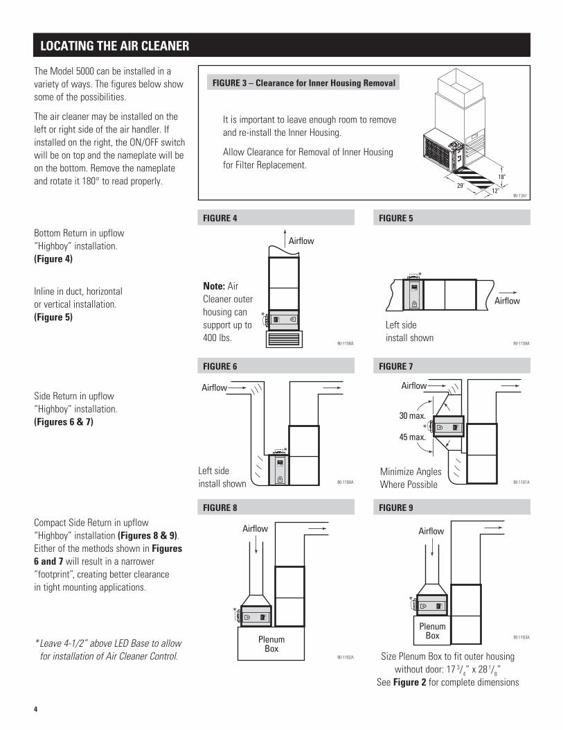
For equipment with EAC terminals: A. Install a single-receptacle outlet to the furnace/air handler wired as shown in Figure 12. B. Use a marker or label to identify the outlet as “EAC USE ONLY”.
For 120-volt equipment without EAC terminals: A. Use an Aprilaire Model 51 Current Sensing Relay to wire a single receptacle outlet as shown in Figure 13. Refer to the
instructions provided with the Model 51 for details on wiring requirements. B. For blowers that are 1/2 hp or larger, clamp the Model 51 around the common wire of the blower – see Figure 14. C. For blowers that are less than 1/2 hp, clamp the Model 51 around two wraps of the common wire as shown in Figure 14. D. Use a marker or label to identify the outlet as “EAC USE ONLY”.
For 240-volt equipment without EAC terminals: A. Install a 2:1 step down transformer to get 120-volt service. Use the instructions provided with the transformer to ensure it
is properly installed. Do not use ground as the common connection for the outlet. B. Follow the instructions “For 120-volt equipment without EAC terminals:” above, except double the number of wraps
around which the Model 51 is clamped.
2. Press the power cord into the slot in the side of the power pack (door) so that the plug is directed toward the installed outlet.
3. Install the door on the housing (with the inner assembly installed in the housing). Place the bottom of the door on the lower door retainer, then swing the door toward the upper door retainer and snap into place.
4. With the door ON/OFF switch in the OFF position, plug the door into the installed outlet.
5. Restore power to the furnace/air handler.
6. Turn on the heating or continuous fan (whichever uses the slowest fan speed) and verify that the blue light on the door is not on (see Figure 15).
7. Turn ON the door switch.
8. Verify that the blue light on the door turns on (see Figure 15).
9. If the light is on, turn off the heating or fan and verify that the light on the door turns off. If the light turns off, installation is complete. If the light on the door does not turn on and off as described, continue with Step 10.
10. If the light stays on after the blower has stopped running, the outlet is continuously live and must be rewired in accordance with Step 1.
11. If the light flashes on, then turns off, or if the light does not come on at all, refer to the TROUBLESHOOTING section on page 14.
CAUTIONDo not plug the air cleaner into an outlet that is always live. The outlet must only be live when the furnace/air handler blower is operating. Failure to properly wire the outlet can result in excessive ozone production.
WARNING120 Volts may cause serious injury from electrical shock. Leave power disconnected until installation is complete.
7
EAC
NEUTRAL
GND
HVAC Equipment Control Center Circuit Board
IT IS COMMON TO SEE SPADE TERMINALS ON THE HVAC EQUIPMENT CONTROL CENTER CIRCUIT BOARD. USE ONLY FULLY INSULATED FITTINGS (FEMALE QUICK DISCONNECTS SHOWN).
3-PRONG OUTLET WIRED TO HVAC
SYSTEM EAC TERMINAL
HVAC EQUIPMENT CONTROL CENTER
GNDGRN
WHT
BLK
HVAC EQUIPMENT
LINE
3-PRONG OUTLET WITH 120-VOLT
SERVICE IN CONDUIT
MODEL 51(SOLD SEPARATELY)
GND
HVAC EQUIPMENT
C
COM
COM
LOW
HI
MODEL 51 RELAY
WIRE NUT
JUNCTION BOX
BLK
WH
TG
RN
LINE VOLTAGE
WIRE NUT
REFER TO THE INSTRUCTIONS PROVIDED WITH THE MODEL 51 FOR WIRING DETAILS
FIGURE 12
FIGURE 14 FIGURE 15
FIGURE 13
ONE “WRAP” - USE FOR 1/2 HP
MOTORS OR LARGER
TWO “WRAPS” - USE FOR
MOTORS LESS THAN 1/2 HP
INCORRECT “WRAP” - DOES
NOT WORK
Unit OFFBlue Light OFF
Unit ONBlue Light ON
90-1155
90-1156
90-1157
90-1150
8
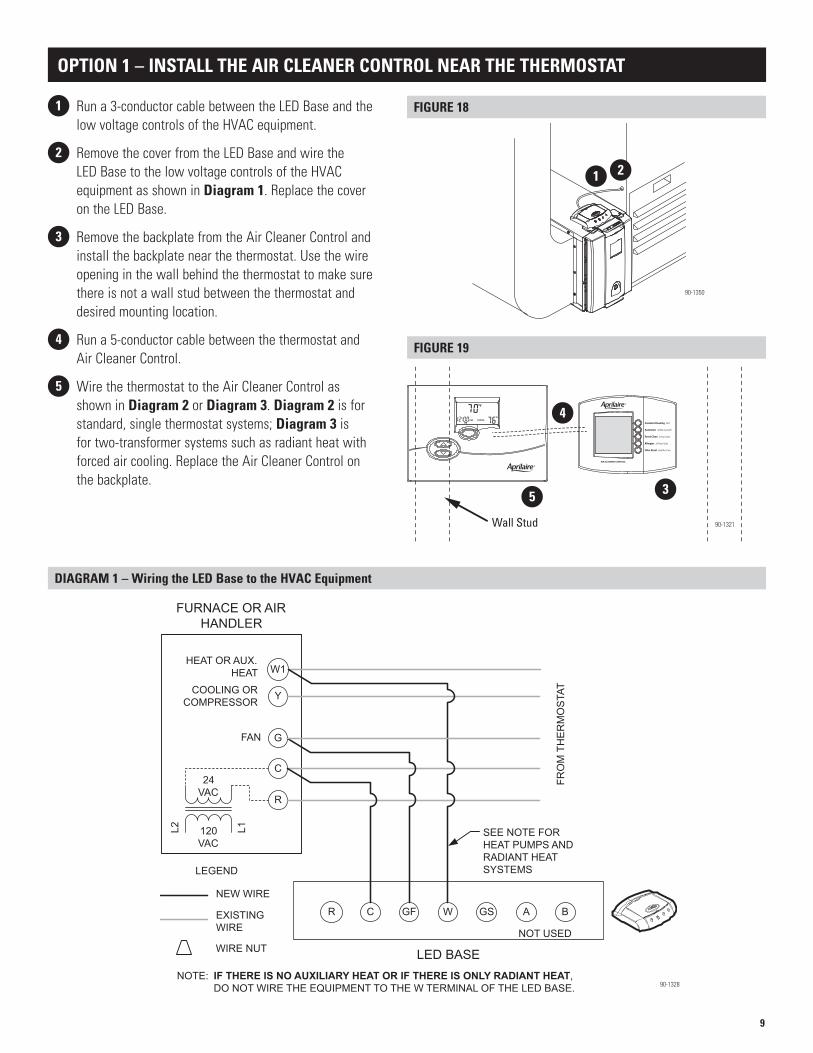
The electronic controls that are included with the air cleaner are used to circulate air through the air cleaner, monitor filter life and inform the user that the air is being cleaned. Users can turn on the blower for a set period of time or adjust it so that the blower is on, either as part of a heating/cooling call or blower only, for a set number of minutes per hour. This requires the Air Cleaner Control to be mounted in an accessible location, and requires 18-22 gauge (standard thermostat cable) wires to be run between the air cleaner components and the HVAC components.
THE AIR CLEANER CONTROL CAN BE MOUNTED:
• Option 1: near the thermostat – see pages 9-10.• Option 2: on the air cleaner in the LED Base,
as shown in Figure 17 – see page 11.• Option 3: near the HVAC equipment – see page 12.
Control
LED Base
INSTALL THE AIR CLEANER CONTROL
FIGURE 17 – Air Cleaner Control Mounted on the Air Cleaner
90-1349
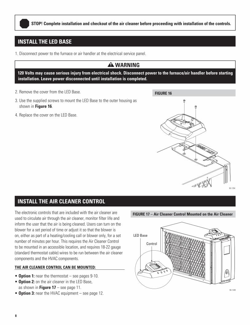
INSTALL THE LED BASE
1. Disconnect power to the furnace or air handler at the electrical service panel.
2. Remove the cover from the LED Base.
3. Use the supplied screws to mount the LED Base to the outer housing as shown in Figure 16.
4. Replace the cover on the LED Base.
STOP! Complete installation and checkout of the air cleaner before proceeding with installation of the controls.
FIGURE 16
90-1354
WARNING120 Volts may cause serious injury from electrical shock. Disconnect power to the furnace/air handler before starting installation. Leave power disconnected until installation is completed.
9
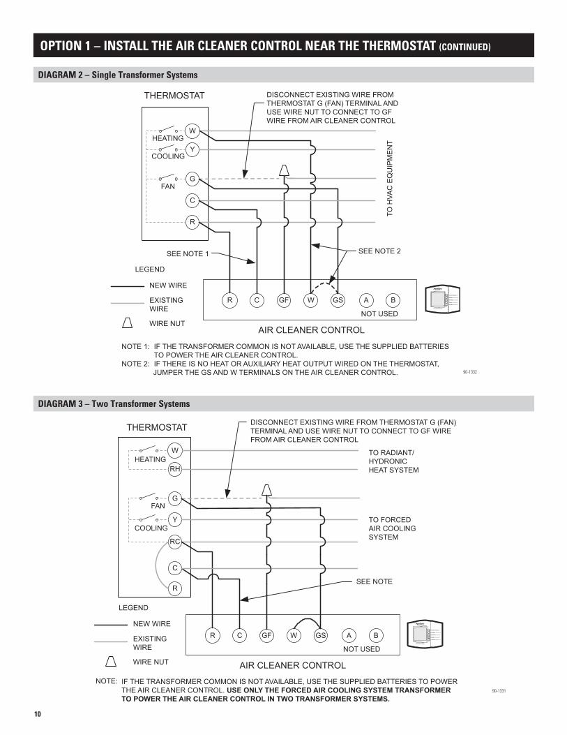
1 Run a 3-conductor cable between the LED Base and the low voltage controls of the HVAC equipment.
2 Remove the cover from the LED Base and wire the LED Base to the low voltage controls of the HVAC equipment as shown in Diagram 1. Replace the cover on the LED Base.
3 Remove the backplate from the Air Cleaner Control and install the backplate near the thermostat. Use the wire opening in the wall behind the thermostat to make sure there is not a wall stud between the thermostat and desired mounting location.
4 Run a 5-conductor cable between the thermostat and Air Cleaner Control.
5 Wire the thermostat to the Air Cleaner Control as shown in Diagram 2 or Diagram 3. Diagram 2 is for standard, single thermostat systems; Diagram 3 is for two-transformer systems such as radiant heat with forced air cooling. Replace the Air Cleaner Control on the backplate.
OPTION 1 – INSTALL THE AIR CLEANER CONTROL NEAR THE THERMOSTAT
R
FURNACE OR AIR HANDLER
C
G
Y
W1
COOLING OR COMPRESSOR
L1L2 120 VAC
24 VAC
HEAT OR AUX. HEAT
FAN
GSWGFCR
LED BASE
SEE NOTE FOR HEAT PUMPS AND RADIANT HEAT SYSTEMS
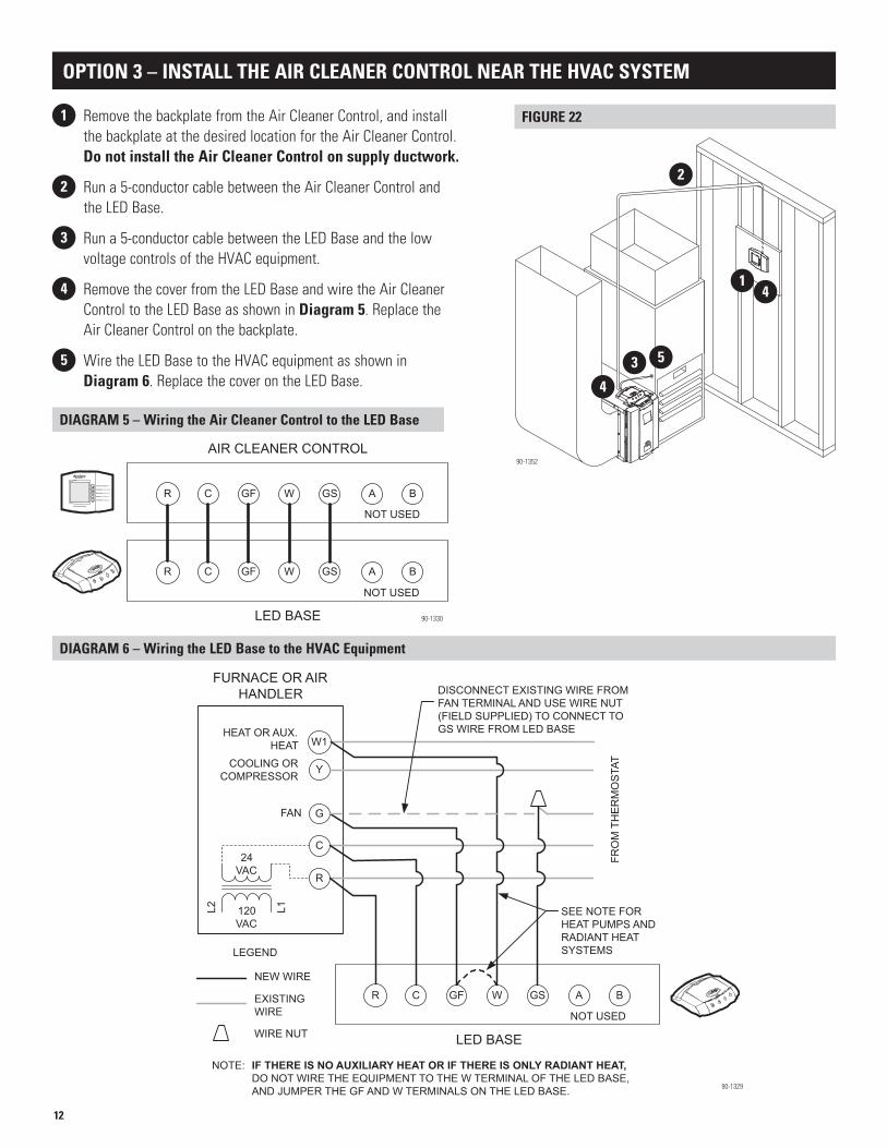
NOTE: IF THERE IS NO AUXILIARY HEAT OR IF THERE IS ONLY RADIANT HEAT, DO NOT WIRE THE EQUIPMENT TO THE W TERMINAL OF THE LED BASE.
NEW WIRE
EXISTING WIRE
LEGEND
WIRE NUT
BA
FRO
M T
HE
RM
OS
TAT
NOT USED
DIAGRAM 1 – Wiring the LED Base to the HVAC Equipment
90-1328
Wall Stud
FIGURE 19
90-1321
4
35
FIGURE 18
90-1350
1 2
10
R
THERMOSTAT
G
Y
W
COOLING
HEATING
FAN
GSWGFCR
AIR CLEANER CONTROL
DISCONNECT EXISTING WIRE FROM THERMOSTAT G (FAN) TERMINAL AND USE WIRE NUT TO CONNECT TO GF WIRE FROM AIR CLEANER CONTROL
NEW WIRE
EXISTING WIRE
LEGEND
WIRE NUT
BA
C
NOTE 1: IF THE TRANSFORMER COMMON IS NOT AVAILABLE, USE THE SUPPLIED BATTERIES TO POWER THE AIR CLEANER CONTROL.
NOTE 2: IF THERE IS NO HEAT OR AUXILIARY HEAT OUTPUT WIRED ON THE THERMOSTAT, JUMPER THE GS AND W TERMINALS ON THE AIR CLEANER CONTROL.
SEE NOTE 1
TO H
VAC
EQ
UIP
ME
NT
SEE NOTE 2
NOT USED
DIAGRAM 2 – Single Transformer Systems
90-1332
RC
THERMOSTAT
Y
G
RH
W
COOLING
HEATING
FAN
GSWGFCR
AIR CLEANER CONTROL
NEW WIRE
EXISTING WIRE
LEGEND
WIRE NUT
BA
R
C
TO RADIANT/HYDRONIC HEAT SYSTEM
TO FORCED AIR COOLING SYSTEM
SEE NOTE
NOT USED
DISCONNECT EXISTING WIRE FROM THERMOSTAT G (FAN) TERMINAL AND USE WIRE NUT TO CONNECT TO GF WIRE FROM AIR CLEANER CONTROL
NOTE: IF THE TRANSFORMER COMMON IS NOT AVAILABLE, USE THE SUPPLIED BATTERIES TO POWER THE AIR CLEANER CONTROL. USE ONLY THE FORCED AIR COOLING SYSTEM TRANSFORMER TO POWER THE AIR CLEANER CONTROL IN TWO TRANSFORMER SYSTEMS.
DIAGRAM 3 – Two Transformer Systems
90-1331
OPTION 1 – INSTALL THE AIR CLEANER CONTROL NEAR THE THERMOSTAT (CONTINUED)
11
90-1351
R
FURNACE OR AIR HANDLER
C
G
Y
W1
COOLING OR COMPRESSOR
L1L2 120 VAC
24 VAC
HEAT OR AUX. HEAT
FAN
GSWGFCR
DISCONNECT EXISTING WIRE FROM FAN TERMINAL AND USE WIRE NUT (FIELD SUPPLIED) TO CONNECT TO GS WIRE FROM LED BASE
NEW WIRE
EXISTING WIRE
LEGEND
WIRE NUT
BA
FRO
M T
HE
RM
OS
TAT
SEE NOTE FOR HEAT PUMPS AND RADIANT HEAT SYSTEMS
NOT USED
LED BASE
NOTE: IF THERE IS NO AUXILIARY HEAT OR IF THERE IS ONLY RADIANT HEAT,DO NOT WIRE THE EQUIPMENT TO THE W TERMINAL OF THE LED BASE,AND JUMPER THE GF AND W TERMINALS ON THE LED BASE.
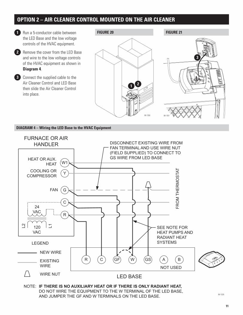
OPTION 2 – AIR CLEANER CONTROL MOUNTED ON THE AIR CLEANER
1 Run a 5-conductor cable between the LED Base and the low voltage controls of the HVAC equipment.
2 Remove the cover from the LED Base and wire to the low voltage controls of the HVAC equipment as shown in Diagram 4.
3 Connect the supplied cable to the Air Cleaner Control and LED Base then slide the Air Cleaner Control into place.
90-1350
FIGURE 20
DIAGRAM 4 – Wiring the LED Base to the HVAC Equipment
FIGURE 21
90-1329
1 2
3
12
LED BASE
AIR CLEANER CONTROL
GSWGFCR BA
GSWGFCR BA
NOT USED
NOT USED
R
FURNACE OR AIR HANDLER
C
G
Y
W1
COOLING OR COMPRESSOR
L1L2 120 VAC
24 VAC
HEAT OR AUX. HEAT
FAN
GSWGFCR
DISCONNECT EXISTING WIRE FROM FAN TERMINAL AND USE WIRE NUT (FIELD SUPPLIED) TO CONNECT TO GS WIRE FROM LED BASE
NEW WIRE
EXISTING WIRE
LEGEND
WIRE NUT
BA
FRO
M T
HE
RM
OS
TAT
SEE NOTE FOR HEAT PUMPS AND RADIANT HEAT SYSTEMS
NOT USED
LED BASE
NOTE: IF THERE IS NO AUXILIARY HEAT OR IF THERE IS ONLY RADIANT HEAT,DO NOT WIRE THE EQUIPMENT TO THE W TERMINAL OF THE LED BASE,AND JUMPER THE GF AND W TERMINALS ON THE LED BASE.
1 Remove the backplate from the Air Cleaner Control, and install the backplate at the desired location for the Air Cleaner Control. Do not install the Air Cleaner Control on supply ductwork.
2 Run a 5-conductor cable between the Air Cleaner Control and the LED Base.
3 Run a 5-conductor cable between the LED Base and the low voltage controls of the HVAC equipment.
4 Remove the cover from the LED Base and wire the Air Cleaner Control to the LED Base as shown in Diagram 5. Replace the Air Cleaner Control on the backplate.
5 Wire the LED Base to the HVAC equipment as shown in Diagram 6. Replace the cover on the LED Base.
FIGURE 22
DIAGRAM 5 – Wiring the Air Cleaner Control to the LED Base
DIAGRAM 6 – Wiring the LED Base to the HVAC Equipment
OPTION 3 – INSTALL THE AIR CLEANER CONTROL NEAR THE HVAC SYSTEM
90-1352
90-1330
90-1329
2
1
3
4
5
4

13
1. Restore power to the HVAC equipment.
2. Set the thermostat mode to OFF and fan to AUTO.
3. The display on the Air Cleaner Control should look like Figure 24. • Verify that there is no activity in the “FILTERING” portion of the display.
4. Press the “Event Clean” button on the Air Cleaner Control. • Verify that the blower starts. • Verify that the “FILTERING” portion of the display sequences (Figure 25). • Verify that the LEDs on the LED base are sequencing on and off
(Figure 26).
5. Press the “Event Clean” button again to cancel the operation.
6. Return the thermostat Mode and Fan to the desired setting.
Refer to the Owner’s Manual for details on the operation of the Air Cleaner Control.
INSTALL THE AIR CLEANER CONTROL
START UP
Filtering barswill sequence on / off
LEDs willsequence on / off
FIGURE 24
FIGURE 25 FIGURE 26
90-1322
90-135390-1322
SET UP
Jumper
FIGURE 23
90-1338
FILTER LIFE INDICATOR – SETTING THE REPLACEMENT FREQUENCY
Set the jumper on the back of the Air Cleaner Control circuit board, as shown in Figure 23, to the desired frequency for filter changes.
TABLE 2 – Filter Change Frequency
Jumper Position Filter Change Setting
OFF One calendar year (365 days)
A 6570 hours of use (9 months of continuous blower run time)
B 4380 hours of use (6 months of continuous blower run time)
C 2190 hours of use (3 months of continuous blower run time)
The factory default setting is OFF.
14
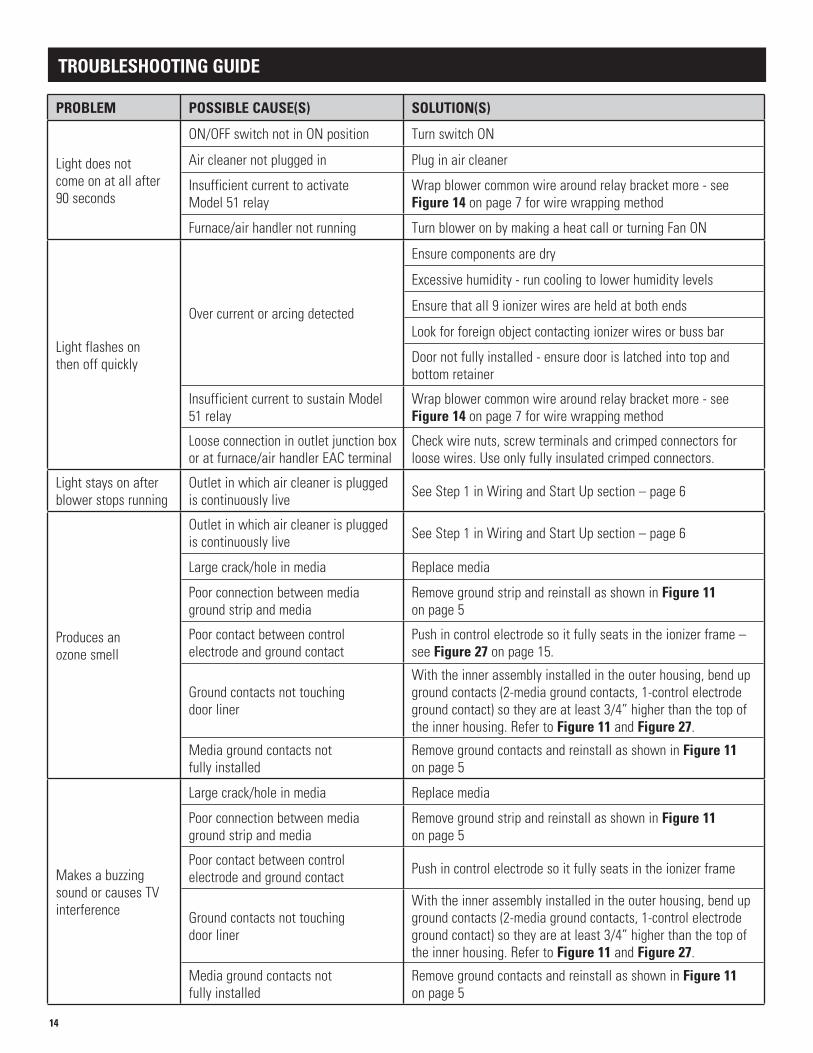
TROUBLESHOOTING GUIDE
PROBLEM POSSIBLE CAUSE(S) SOLUTION(S)
Light does not come on at all after 90 seconds
ON/OFF switch not in ON position Turn switch ON
Air cleaner not plugged in Plug in air cleaner
Insufficient current to activate Model 51 relay
Wrap blower common wire around relay bracket more - see Figure 14 on page 7 for wire wrapping method
Furnace/air handler not running Turn blower on by making a heat call or turning Fan ON
Light flashes on then off quickly
Over current or arcing detected
Ensure components are dry
Excessive humidity - run cooling to lower humidity levels
Ensure that all 9 ionizer wires are held at both ends
Look for foreign object contacting ionizer wires or buss bar
Door not fully installed - ensure door is latched into top and bottom retainer
Insufficient current to sustain Model 51 relay
Wrap blower common wire around relay bracket more - see Figure 14 on page 7 for wire wrapping method
Loose connection in outlet junction box or at furnace/air handler EAC terminal
Check wire nuts, screw terminals and crimped connectors for loose wires. Use only fully insulated crimped connectors.
Light stays on after blower stops running
Outlet in which air cleaner is plugged is continuously live See Step 1 in Wiring and Start Up section – page 6
Produces an ozone smell
Outlet in which air cleaner is plugged is continuously live See Step 1 in Wiring and Start Up section – page 6
Large crack/hole in media Replace media
Poor connection between media ground strip and media
Remove ground strip and reinstall as shown in Figure 11 on page 5
Poor contact between control electrode and ground contact
Push in control electrode so it fully seats in the ionizer frame – see Figure 27 on page 15.
Ground contacts not touching door liner
With the inner assembly installed in the outer housing, bend up ground contacts (2-media ground contacts, 1-control electrode ground contact) so they are at least 3/4” higher than the top of the inner housing. Refer to Figure 11 and Figure 27.
Media ground contacts not fully installed
Remove ground contacts and reinstall as shown in Figure 11 on page 5
Makes a buzzing sound or causes TV interference
Large crack/hole in media Replace media
Poor connection between media ground strip and media
Remove ground strip and reinstall as shown in Figure 11 on page 5
Poor contact between control electrode and ground contact Push in control electrode so it fully seats in the ionizer frame
Ground contacts not touching door liner
With the inner assembly installed in the outer housing, bend up ground contacts (2-media ground contacts, 1-control electrode ground contact) so they are at least 3/4” higher than the top of the inner housing. Refer to Figure 11 and Figure 27.
Media ground contacts not fully installed
Remove ground contacts and reinstall as shown in Figure 11 on page 5
15
Inner Housing
Ionizer Frame
ControlElectrode
Control Electrode
Ionizer Frame
ControlElectrodeGroundContact
Media GroundContacts
IonizerWires
Bus Bar
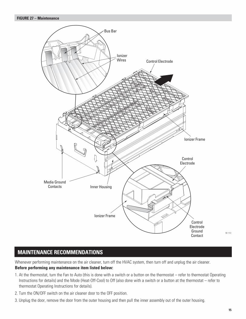
FIGURE 27 – Maintenance
MAINTENANCE RECOMMENDATIONS
Whenever performing maintenance on the air cleaner, turn off the HVAC system, then turn off and unplug the air cleaner. Before performing any maintenance item listed below:
1. At the thermostat, turn the Fan to Auto (this is done with a switch or a button on the thermostat – refer to thermostat Operating Instructions for details) and the Mode (Heat-Off-Cool) to Off (also done with a switch or a button at the thermostat – refer to thermostat Operating Instructions for details).
2. Turn the ON/OFF switch on the air cleaner door to the OFF position.
3. Unplug the door, remove the door from the outer housing and then pull the inner assembly out of the outer housing.
90-1151
16
RESEARCH PRODUCTS CORPORATIONP.O. BOX 1467 • MADISON, WI 53701-1467 • PHONE: 800/334-6011 • FAX: 608/257-4357 • www.aprilairecontractor.com
10007971 5.08B2701048A
APPLICATIONS WITH A HUMIDIFIER
An Aprilaire® Automatic Humidifier can be mounted upstream from the air cleaner.
MAINTENANCE RECOMMENDATIONS (CONTINUED)
CLEAN THE CONTROL ELECTRODEMost homes will require cleaning of the control electrode once a year, while a few homes may require cleaning more often. The primary purpose of the control electrode is to develop a good ionization field, but it does attract particles and will filter out larger particles like pet hair. Check this item 6 months after initial installation to determine how often it should be cleaned in the future.
• If build up of larger particles that parially block the airflow is occurring, clean the control electrode every 6 months.• If there is only dust build up occurring, clean the control electrode every 12 months.
Procedure:1. Lay the inner housing assembly on a flat surface with the control electrode facing up (see Figure 27).2. Slide the control electrode out of the ionizer frame and wipe with a clean cloth, or vacuum with a brush attachment.3. Return the thermostat Fan and Mode selectors to their appropriate settings.
REPLACE THE MEDIAThe media attracts and neutralizes ionized particles. Most homes require replacement of the media once a year. How quickly build up occurs will depend on many factors including lifestyle, construction details and environment.
• Check the media 6 months after initial installation. If the media appears dark grey or brown, replace it and check the media for replacement every 6 months thereafter.
• Replace the media no less often than once per year.• Always use Genuine Aprilaire Model 501 Replacement Media. The Model 5000 is designed to work only with Genuine
Aprilaire 501 Replacement Media. Use of other media will damage your Model 5000 Electronic Air Cleaner.Procedure: Follow the instructions on the 501 media carton.
CLEAN THE IONIZER WIRESParticles will normally build up on the positively charged ionizer wires during operation. The ionizer wires should be cleaned to maintain the highest level of filtration.
• Clean the ionizer wires at least once a year.Procedure:1. Lay the inner assembly on a flat surface with the control electrode facing up (see Figure 27).2. Slide the control electrode out of the ionizer frame and set it aside.3. Using 200 grit sandpaper or an abrasive dish scrubber, clean each of the nine ionizer wires. Even if the wires don’t appear dirty,
clean each one. Do not use steel wool as this material readily sheds.4. Replace the control electrode in the ionizer frame, return the inner assembly to the outer housing, reinstall the door, and turn the
ON/OFF switch to the ON position.5. Return the thermostat Fan and Mode selectors to their appropriate settings.
CLEAN THE INNER ASSEMBLYDust will collect on all parts of the air cleaner, which is normal.
• Clean the inner housing and ionizer frame once a year.Procedure:1. Use a vacuum with a brush attachment or a cloth to wipe off collected dust on the inner housing and ionizer frame.2. Return the inner assembly to the outer housing, reinstall the door, and turn the ON/OFF switch to the ON position.3. Return the thermostat Fan and Mode selectors to their appropriate settings.
CAUTIONDo not install an atomizing humidifier upstream from the air cleaner.