Embed Size (px)
Citation preview

April 4 - 5, 2000
at Lewis FieldGLENN RESEARCH CENTER
Aero-Space Propulsion Simulation and Modeling
Dr. John K. Lytle
Chief, Computing and Interdisciplinary Systems Office

2
Provide next generation design tools and experimental aircraft to increase design confidence, and cut the development cycle time for aircraft in half.
NASA Goals Directly Supported by Simulation and Modeling

3
• High Fidelity, Physics-based Simulations•Combustion•Turbomachinery• Aeroelasticity• Probabilistic Methods• Full System
• Virtual Design Environment, Life Cycle Simulation
Outline
Advanced Space Transportation Program (MSFC)
High Performance Computing and Communications Program (ARC)
Intelligent Synthesis Environment Program (LaRC)
Intelligent Systems Program (ARC)
Information Technology R&T Base Program (ARC)
Aero-Space Propulsion and Power R&T Base (GRC)

4
Fuel Nozzle Flow
Cold and Hot Isotherm Interactions
Midplane Temperature Contour
Midplane Total Pressure Contour
The National Combustion Code is an integrated system of computer codes that takes advantage of solid modeling and automated meshing of complex geometries.
The National Combustion Code uses unstructured meshes and parallel computing. Physical models include: a turbulence module containing the nonlinear k-epsilon models; conventional reduced chemical kinetics or the Intrinsic Low Dimensional Manifold (ILDM) approach; a spray module; and a joint probability density function for species and enthalpy.
Th
e N
atio
nal
Co
mb
ust
ion
Co
de

5
APNASA 21 Blade Row Compressor Simulation Turnaround Time Reduced by a Factor of 400:1
COMPUTER HARDWAREIMPROVEMENTS
BASELINE ANALYSIS1992
PARALLELPROCESSING
ALGORITHMICCHANGES
INCREASEDRESOLUTION
~ ÷ 40
~ 2.4 X
~ ÷ 6
Factors Influencing Turnaround TimeEstimated Turnaround TimeEstimated Turnaround Time
Ho
urs
~ ÷ 4

6
0.29
0.3
0.31
0.32
0.33
0.34
0.35
0 200 400 600 800 1000 1200 1400 1600 1800
time step
Dynamic Stress Prediction
Unsteady Aerodynamic Loading
Forced Response
Aeroelastic Analysis using TURBO
• TURBO version for fluid-structure interaction analysis being developed
– three-dimensional, viscous, unsteady aerodynamics– Purge flow, real gas effects, K-Baldwin-Lomax
turbulence models
– phase-lagged boundary conditions reduce computational domain to one blade passage per blade row
– dynamic grid deformation to simulate blade vibration
• Code validated for flutter analysis– Pratt & Whitney, Honeywell and Rolls-Royce Allison used
code on in-house data to predict flutter
• Validation in progress for forced response– GE validating the code using in-house data
Mass Flow
FlutterMode 1Mode 2
Aer
o-D
amp
ing
No FlutterFlutter

7
Probability of Failure
Response (stress)
Resistance (strength)
Structural Response
Probabilistic Loads
P
Mechanical
P
Thermal
Information for Reliability
& Risk Assessment
Probability of Occurrence
Probabilistic Materials Behavior
P
Geometry and Material
Multidisciplinary Probabilistic Heat Transfer/Structural analysis code
Probabilistic Simulation of Component Reliabilityusing NESTEM

8
Validated Models
Fluids Heat Transfer Combustion Structures Materials Controls Manufacturing Economics
Rapid AffordableComputation of:
Performance Stability Cost Life CertificationRequirements
Integrated Interdisciplinary Analysisand Design of Propulsion Systems
High Performance Computing
Parallel Processing Object-oriented Architecture Expert Systems Interactive 3-D Graphics High Speed Networks Database Management Systems
A Numerical Test Cell for Aerospace Propulsion SystemsA Numerical Test Cell for Aerospace Propulsion Systems

9
Aero-Space Propulsion Simulation and Modeling
Government•NASA
•ARC•LaRC•MSFC
•Air Force Research Laboratory•Naval Air Research Center•Arnold Engineering and Development Center•Department of Energy
Industry•General Electric•Pratt&Whitney•Honeywell•Rolls-Royce Allison•Williams Intl.•Teledyne Continental•Boeing•Lockheed-Martin
A Government/Industry/University Partnership
University•Stanford•Cleveland State•Winston-Salem•IUPUI•Mississippi State

10
• Numerical Zooming and Geometry Access Standards through NPSS for physics based modeling
• NPSS Common System Model expected to save Aircraft Industry $50M/year
Simulation Environment
•Computationally efficient (cross-platform operation, parallel processing)
•Modular design (object-oriented:“Plug-n-Play” system model assembly, easily modified and expanded)
•Provide a common modeling tool for U.S. Government, aerospace industry, and academia

11

12
The Road to Full 3D Overnight Engine Simulation
Full 3-D Primary Flow PathScheduled for Completion
2Q FY2001
High Pressure CoreScheduled for Completion
3Q FY2000
Compressor SimulationCompleted 1998
Combustion SubsystemCompleted 4Q FY1999
Turbine SubsystemCompleted FY1998
Single StageCompleted 1990
Single Blade RowCompleted 1985
CD-00-79981
Fan/BoosterScheduled for Completion3Q FY2000
NPSS for Space Transportation

13
Engine-Airframe Structural Simulations Provide High Fidelity Analysis and Assessment of Blade-Out Event
NASA Glenn, General Electric Aircraft Engines, Pratt & Whitney, and Boeing have teamed to develop new simulation tools for engine-airframe structural systems. Development of these tools will enable high-fidelity
analyses of blade-out events, more credible design of engine containment systems and improvements in blade-out margin-of-safety predictions.
Mathematical Modeling of Turbomachine Rotors
Physics Based Blade Loss Modeling
Industry/Government Standard Simulation
Procedures
14
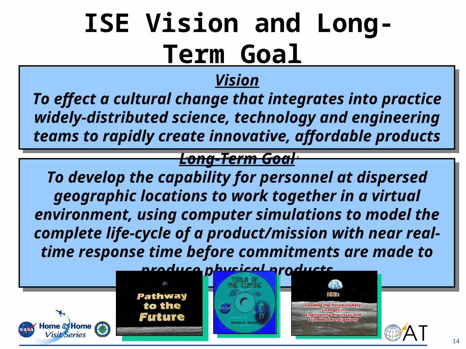
ISE Vision and Long-Term Goal
VisionTo effect a cultural change that integrates into practice widely-
distributed science, technology and engineering teams to rapidly create innovative, affordable products
VisionTo effect a cultural change that integrates into practice widely-
distributed science, technology and engineering teams to rapidly create innovative, affordable products
Long-Term GoalTo develop the capability for personnel at dispersed geographic
locations to work together in a virtual environment, using computer simulations to model the complete life-cycle of a product/mission with near real-time response time before
commitments are made to produce physical products

15
ISE Will Enable Tomorrow What Cannot Be Easily Done Today
•Comprehensive life-cycle trade-studies to: – reduce design cycle time and testing– reduce redesign and rework, – reduce maintenance costs– increase performance and safety
• Bound uncertainties arising from assumptions, scarcity of knowledge and unknowns
• Comprehensive and rapid mission life-cycle simulations will minimize the risks and maximize the benefits
• Provide a means for productive teaming of the best and brightest people and capabilities
• Create and assess new innovative design options and new technologies from anywhere and at anytime
A
•••
•••
•
•• •• •
16
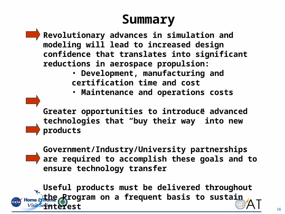
SummaryRevolutionary advances in simulation and modeling will lead to increased design confidence that translates into significant reductions in aerospace propulsion:
• Development, manufacturing and certification time and cost• Maintenance and operations costs
Greater opportunities to introduce advanced technologies that “buy their way” into new products
Government/Industry/University partnerships are required to accomplish these goals and to ensure technology transfer
Useful products must be delivered throughout the Program on a frequent basis to sustain interest

17
EngineeringEngineering ApplicationsApplications
Computing TestbedsComputing Testbeds
SimulationSimulationEnvironmentEnvironment
• Code Parallelization• 3–D Subsystems/System
Gov’t/Industry Collaborative Effort Object - Oriented Programming CAD Geometry Interface
Coupled Aero-Thermal-Structural Analysis
Multi-physics Methods
0–D Engine/1–D Compressor
0–D Core/3–D LP Subsystem
High-Speed Networks PC Cluster Metacenter Computing
Seamless Integration ofData, Analysis Tools andComputing Resources
High Fidelity, Large Scale Simulations
Low-Cost, DistributedParallel Computing
Major Elements of NPSS

18
APNASA Coupled Flow Simulation of High Pressure-Low Pressure Turbines Results in Significant Fuel Savings
Objective:Create a high-fidelity computer simulation of the flow through a full modern high bypass ratio turbofan engine.
Approach:Using a modular approach to the full engine simulation goal, a flow simulation of the tightly coupled high pressure and low pressure turbines has been completed. The computer simulation was performed using NASA’s 3-D average passage approach (APNASA). The simulation was done using 121 processors of a Silicon Graphics Origin cluster with a parallel efficiency of 87% in 15 hours.
Significance:The accurate and rapid simulation of a large turbine subsystem enabled designers to reduce turbine interaction losses in dual-spool engines by 50%. This will result in a $3 million/year savings in fuel costs for a typical fleet of commercial aircraft.
Point of Contact: Joseph P. Veres (216)433-2436
Low PressureTurbine
High Pressure Turbine
Transition Duct