Embed Size (px)
Citation preview

April 1999 LAN and WAN Standards/Habib Youssef
1
LAN and WAN Standards
Habib Youssef, Ph.D.
[email protected] of Computer Engineering King Fahd University of Petroleum &
MineralsDhahran, Saudi Arabia

April 1999 LAN and WAN Standards/Habib Youssef
2
Networks are classified on the basis of geographic span.» Local Area Networks (LANs)» Metropolitan Area Networks (MANs)» Wide Area Networks (WANs)
The difference in geographical extent between WANs and LANs account for significant differences in their respective design issues.

April 1999 LAN and WAN Standards/Habib Youssef
3
Local Area Networks(LANs)
April 1999 LAN and WAN Standards/Habib Youssef
4
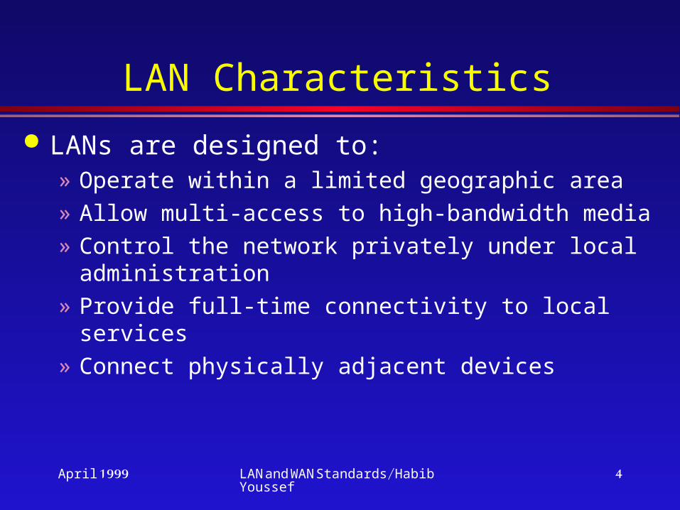
LAN Characteristics
LANs are designed to:» Operate within a limited geographic area» Allow multi-access to high-bandwidth media» Control the network privately under local
administration» Provide full-time connectivity to local services» Connect physically adjacent devices
April 1999 LAN and WAN Standards/Habib Youssef
5
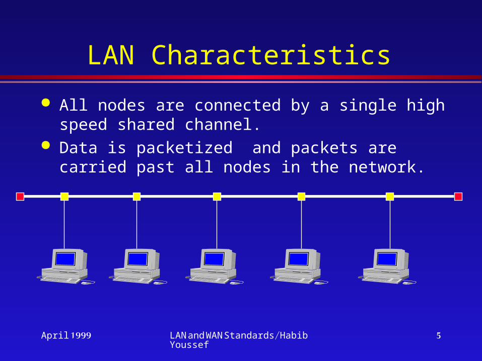
LAN Characteristics
All nodes are connected by a single high speed shared channel.
Data is packetized and packets are carried past all nodes in the network.

April 1999 LAN and WAN Standards/Habib Youssef
6
LAN Characteristics
Transmission Medium» Twisted pair, Coax, CATV, Fiber Optic, or Wireless.
Topology: Star, Bus, Ring Transmission method: Base vs
Broadband Medium Access Technique
» Random Access (CSMA/CD)» Controlled Access (Token Passing)
April 1999 LAN and WAN Standards/Habib Youssef
7
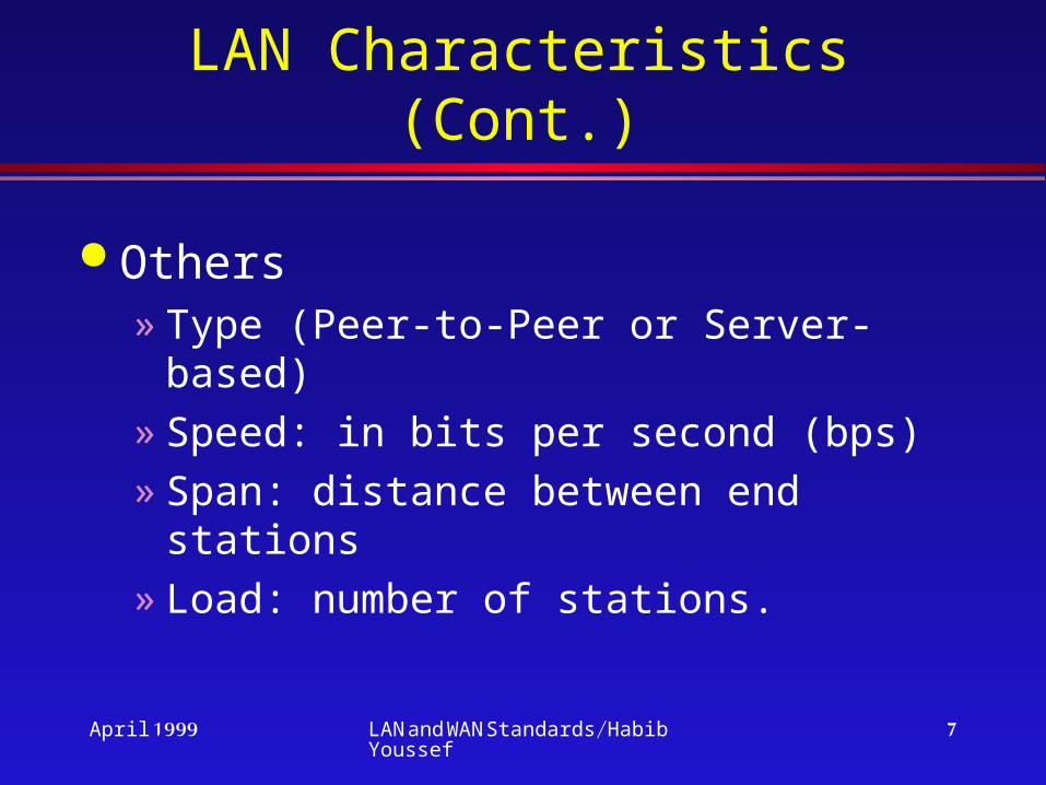
LAN Characteristics (Cont.)
Others» Type (Peer-to-Peer or Server-based)» Speed: in bits per second (bps)» Span: distance between end stations» Load: number of stations.

April 1999 LAN and WAN Standards/Habib Youssef
8
Server-Based LANs
Server-based: A server-based network consists of a group of user-oriented PCs called clients that request and receive network services from specialized computers called servers.

April 1999 LAN and WAN Standards/Habib Youssef
9
Peer-to-Peer LANs
Peer-to-peer: A peer-to-peer network is a group of user-oriented PCs that basically operate as equals. Each PC is called a peer. The peers share resources, such as files and printers, but no specialized servers exists. Each peer is responsible for its own security, and, in a sense, each peer is both a client and a server.

April 1999 LAN and WAN Standards/Habib Youssef
10
Peer-to-Peer Networking (Workgroup)
Resources are distributed throughout the network on computer systems that may act as both service requesters and service providers.
The user of each PC is responsible for the administration and sharing of resources for his PC.
Ideal for small organizations where security is not of concern.
April 1999 LAN and WAN Standards/Habib Youssef
11
LAN Standards

April 1999 LAN and WAN Standards/Habib Youssef
12
MAC Standards
CSMA (Carrier Sense Multiple Access) Protocols
CSMA/CD (Ethernet), Token Bus, Token Ring, FDDI, 100VG-AnyLAN
Wavelength Division Multiple Access Protocols
Wireless LAN Protocols

April 1999 LAN and WAN Standards/Habib Youssef
13
CSMA/CD(CSMA with Collision Detection)
CSMA/CD:» 1. if the medium is idle,
transmit; else, go to step 2.» 2. if the medium is busy,
continue to listen until the channel is idle, then transmit.
» 3. if a collision is detected during transmission, transmit a brief jamming signal
» 4. after transmitting a jamming signal, wait a random amount of time, then attempt to transmit.
Frame Frame Frame Frame

April 1999 LAN and WAN Standards/Habib Youssef
14
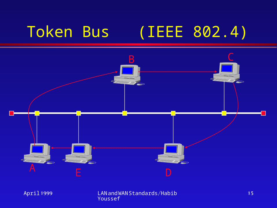
Token Bus (IEEE 802.4) Disadvantages of IEEE 802.3 CSMA/CD:
» Unpredictable delays» No support for priorities
Physically, the token bus is a linear cable onto which stations are attached. Logically, stations are organized into a ring.
A special control frame called token is transmitted from one station to the next, with each station knowing the addresses of the stations to its ``left’’ and ``right’’.
Token bus defines four priority classes: 0, 2, 4, and 6 for traffic, with 0 the lowest and 6 the
highest.
April 1999 LAN and WAN Standards/Habib Youssef
15
Token Bus (IEEE 802.4)
A
CB
DE
April 1999 LAN and WAN Standards/Habib Youssef
16
TOKEN RING
IEEE 802.5 Medium Access Protocol The token ring technique is based on the use of a
small frame, called a token that circulates.» A station wishing to transmit must wait until it
detects a token passing by. » It then seizes the token by changing one bit in
the token which transforms it from a token into a start-of-frame sequence for a data frame.
» The station then appends and transmits the remainder of the fields needed to construct a data frame.
April 1999 LAN and WAN Standards/Habib Youssef
17
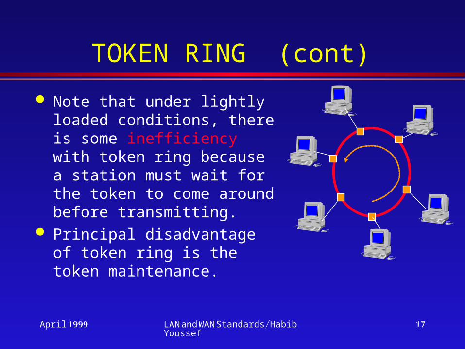
TOKEN RING (cont)
Note that under lightly loaded conditions, there is some inefficiency with token ring because a station must wait for the token to come around before transmitting.
Principal disadvantage of token ring is the token maintenance.

April 1999 LAN and WAN Standards/Habib Youssef
18
Token Ring Priority The 802.5 standard includes a specification for
an optional priority mechanism. Eight levels of priority are supported by providing two 3-bit fields in each data frame and token: a priority field and a reservation field.
P(f): priority of frameP(s): service priority; priority of current tokenR(s): reservation value in current token
» A station wishing to transmit must wait for a token with P(s) <= P(f).
» While waiting, a station may reserve a future token at its priority level P(f).

April 1999 LAN and WAN Standards/Habib Youssef
19
FDDI The FDDI standard specifies a ring topology
operating at 100 Mbps. Optical fiber or twisted pair are used for medium.
» Optical fiber uses 4B/5B NRZI encoding. Maximum length between repeaters is 2 km. Maximum number of repeaters is 100.
» Two twisted pair media are specified: 100-ohm Category 5 unshielded twisted pair and 150-ohm shielded twisted pair. Maximum length between repeaters is 100m . Maximum number of repeaters is 100.

April 1999 LAN and WAN Standards/Habib Youssef
20
FDDI as a Campus Backbone
Token Ring Ethernet
Token Ring
Ethernet
Ethernet
Token Ring
All of the protocols areconverted to the FDDI
transport protocol
Data is Bridged/Routed from the high-speed Backbone
to destination LAN

April 1999 LAN and WAN Standards/Habib Youssef
21
FDDI Strengths
+ FDDI is tailor-made and very effective as a high-speed LAN for workstation traffic and as a Backbone for LANs.
+ Provides a framework for inter-networking between various LAN protocols.

April 1999 LAN and WAN Standards/Habib Youssef
22
FDDI Strengths (Contd.)
+ Compared to legacy LANs, FDDI provides greater data capacity and performance, transmitting at 100 Mbps.
+ Can accommodate large networks of up to 500 Backbone nodes.

April 1999 LAN and WAN Standards/Habib Youssef
23
FDDI Strengths (Contd.)
+ Because of its dual-ring architecture, FDDI offers a high degree of network availability & reliability.
+ Using Token passing, traffic is dealt with on a deterministic basis.
+ Provides long distance communication
(Ring perimeter can be 100 Km with a distance of up to 2Km between Stations)

April 1999 LAN and WAN Standards/Habib Youssef
24
FDDI Weaknesses
-- Can accommodate LAN traffic only. Not capable for transporting real-time signals (voice, host-to-terminal, etc.)
-- Non scaleable (fixed at 100 Mbps).
-- High implementation cost (Processor intensive).
April 1999 LAN and WAN Standards/Habib Youssef
25
How FDDI Works?
It is a token passing fiber ring with a data rate of 100 Mbps.
Ring can be as large as 100 Km with a distance of 2 Km between stations.
Most prevalent standard is multi-mode fiber. However, some manufacturers are producing multi-mode to single-mode FDDI adapter.
April 1999 LAN and WAN Standards/Habib Youssef
26
How FDDI Works? (Contd.)
Others proposed amendments to the standard to support FDDI on twisted pair (CDDI).
Routers are used to convert competing LAN protocols to FDDI and back.

April 1999 LAN and WAN Standards/Habib Youssef
27
How FDDI Works? (Contd.)
Dual-counter rotating rings:» Primary link for carrying data.» Secondary link for failure recovery.
In the event of a node or cable failure, the data on the primary link wraps on to the secondary link, making a U-turn, thus maintaining ring integrity.

April 1999 LAN and WAN Standards/Habib Youssef
28
How FDDI Works? (Contd.)
FDDI FDDI
FDDI
XX
April 1999 LAN and WAN Standards/Habib Youssef
29
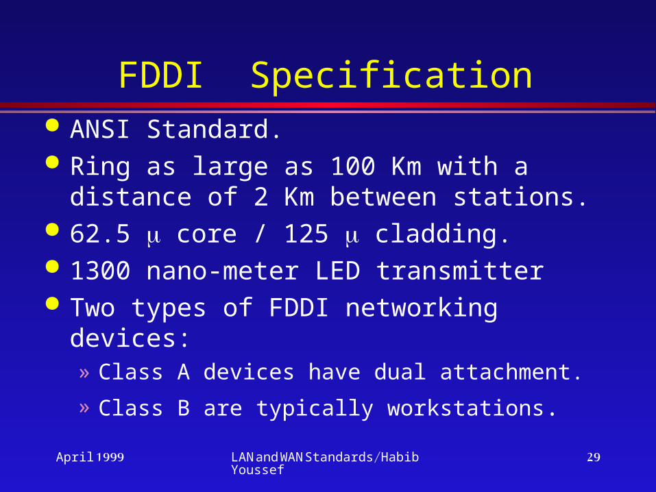
FDDI Specification ANSI Standard. Ring as large as 100 Km with a distance
of 2 Km between stations. 62.5 core / 125 cladding. 1300 nano-meter LED transmitter Two types of FDDI networking devices:
» Class A devices have dual attachment.
» Class B are typically workstations.
April 1999 LAN and WAN Standards/Habib Youssef
30
FDDI Specification
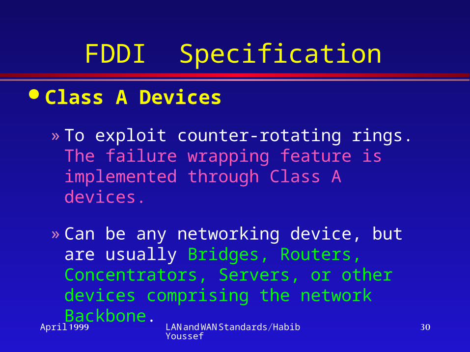
Class A Devices
» To exploit counter-rotating rings. The failure wrapping feature is implemented through Class A devices.
» Can be any networking device, but are usually Bridges, Routers, Concentrators, Servers, or other devices comprising the network Backbone.
April 1999 LAN and WAN Standards/Habib Youssef
31
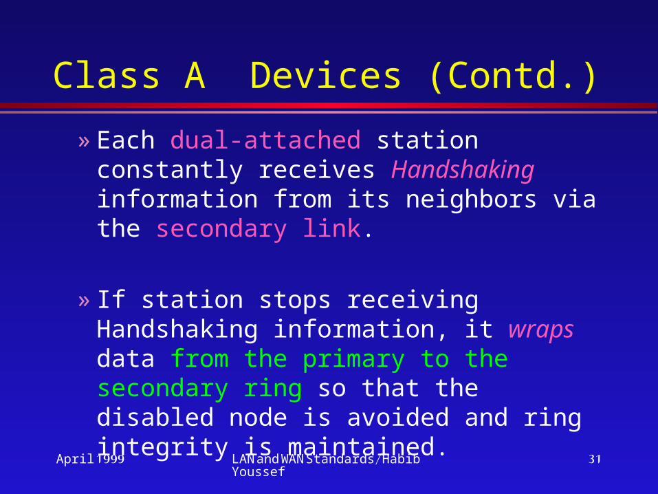
Class A Devices (Contd.)
» Each dual-attached station constantly receives Handshaking information from its neighbors via the secondary link.
» If station stops receiving Handshaking information, it wraps data from the primary to the secondary ring so that the disabled node is avoided and ring integrity is maintained.

April 1999 LAN and WAN Standards/Habib Youssef
32
FDDI Specification (Contd.)
Class B Devices» They are single-attached stations. » They are typically workstations, printers, and
other nodes that are attached only indirectly to the primary link.
» They access the ring by plugging into a concentrator that is dual-attached to the ring.
An FDDI network can operate with up to 500 dual-attached stations.

April 1999 LAN and WAN Standards/Habib Youssef
33
FDDI Specification (Contd.)
A
A
B
B
B
BB B
B
B
B
B
B
Class A
April 1999 LAN and WAN Standards/Habib Youssef
34
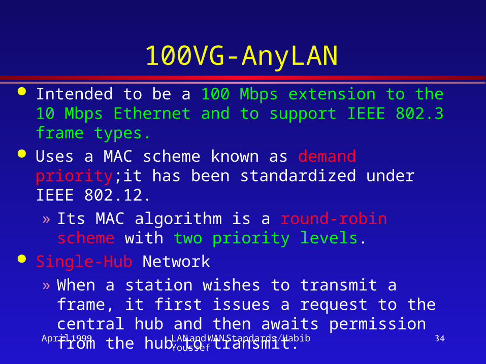
100VG-AnyLAN Intended to be a 100 Mbps extension to the 10
Mbps Ethernet and to support IEEE 802.3 frame types.
Uses a MAC scheme known as demand priority;it has been standardized under IEEE 802.12.» Its MAC algorithm is a round-robin scheme with
two priority levels. Single-Hub Network
» When a station wishes to transmit a frame, it first issues a request to the central hub and then awaits permission from the hub to transmit.

April 1999 LAN and WAN Standards/Habib Youssef
35
» A station must designate each request as normal-priority or high-priority.
» The central hub continually scans all of its ports for a request in round-robin fashion.
» The central hub maintains two pointers: a high-priority pointer and a normal-priority pointer.
» If at any time there are no pending high-priority requests, the hub will grant any normal-priority requests that it encounters.
100VG-AnyLAN (contd.)

April 1999 LAN and WAN Standards/Habib Youssef
36
Hierarchical Network» All of the end-system ports on all hubs are treated
as a single set of ports for purposes of round-robin.» Port ordering is done preorder traversal:
– Visit the root– Traverse the subtrees from left to right.
100 VG-AnyLAN (contd.)

April 1999 LAN and WAN Standards/Habib Youssef
37
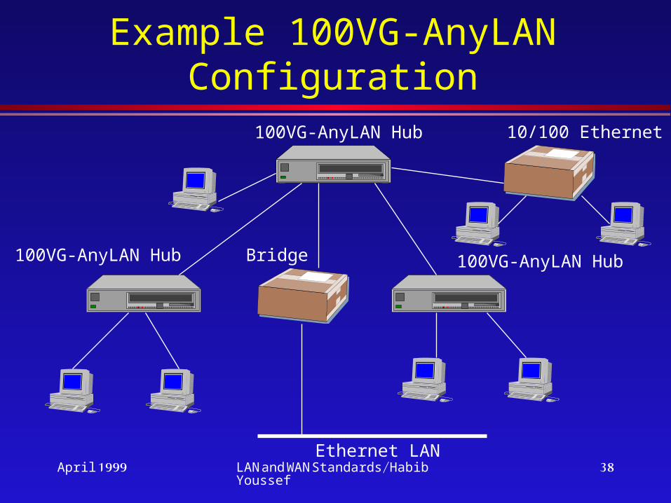
100VG-AnyLAN (contd.)
Hierarchical topology» There is a single root Hub (at level 1)» A level 1 Hub may have one or more
subordinate level 2 hubs» A level 2 hub can have one or many
subordinate level 3 hubs, and so on, to an arbitrary depth
Hub is responsible for converting between 802.3 and 802.5 frame formats if necessary
April 1999 LAN and WAN Standards/Habib Youssef
38
Example 100VG-AnyLAN Configuration
100VG-AnyLAN Hub
100VG-AnyLAN Hub 100VG-AnyLAN HubBridge
Ethernet LAN
10/100 Ethernet

April 1999 LAN and WAN Standards/Habib Youssef
39
MAC of 100VG-AnyLAN(Single hub network)
The MAC algorithm for 802.12 is a round-robin scheme with two priority levels
A station wishing to transmit» it first issues a request to the central hub» it then awaits permission from the hub to
transmit» A station must designate each request as
normal priority or high priority

April 1999 LAN and WAN Standards/Habib Youssef
40
Single hub LAN (contd.)
» The central hub continually scans all of its ports for request in round-robin fashion
» The hub maintains two pointers– a high priority pointer and– a low priority pointer
» During one cycle, the hub grants each high priority request in the order encountered
» When there are no pending high priority requests, the hub grants normal priority requests in the order encountered

April 1999 LAN and WAN Standards/Habib Youssef
41
100VG-AnyLAN Priority Scheme
High priority pointer
Normal priority pointer
High-priority
queue empty
Time-out
REQ-H
REQ-N
Request from port k placed in
position k
Request from port k placed in
position kTransmit
Frame
n 12
3
4
5
76
889AB
C
...
n 1 2
3
4
5
6789A
B
C
..
.
If a request remains in the normal priority buffer for too long (default= 500 ms), it is moved to the corresponding position in the high-priority buffer.

April 1999 LAN and WAN Standards/Habib Youssef
42
Hierarchical LAN
The set of all hubs are treated logically as one single hub» The port order is generated by performing a
pre-order traversal of the tree (depth-first)– Visit the root– traverse the subtrees from left to right
» Each hub is running its own round-robin algorithm to service end-systems directly attached to it.

April 1999 LAN and WAN Standards/Habib Youssef
43
Port Ordering in a Two-Level IEEE 802.12 Network
R1 2 3 4 5 6 7
A1 2 k
B1 2 k
Level 1 “Root” Repeater
Level 2 RepeaterLevel 2 Repeater
3-1 3-k 5-1 5-2 5-n
1-1 1-2
1-4
1-6 1-7

April 1999 LAN and WAN Standards/Habib Youssef
44
Example Frame Sequence in a Single-Repeater Network
1
2
3
4
5
6
7
8
High priority request
Normal priority request
High priority frame
Normal priority frame
Ports
1
2
3
4
5
6
7
8
9

April 1999 LAN and WAN Standards/Habib Youssef
45
IEEE 802.3 CSMA/CDLabeling Terminology
IEEE 802.3 CSMA/CD
100BASE-X
100BASE-TX
Two Category 5 UTP
Two STP
100BASE-FX
Two Optical Fiber
100BASE-T4
Four Category 3 or Category 5 UTP

April 1999 LAN and WAN Standards/Habib Youssef
46
IEEE 802.3 100BASE-T Physical Layer Medium Alternatives
_________________________________________________________________
100BASE-TX 100BASE-FX 100BASE-T4_________________________________________________________________
Transmission Two pair Two pair Two optical fibers Four pair, cat
medium STP cat 5 UTP 3,4 or 5 UTP
Signaling 4B5B,NRZI 4B5B, NRZI 4B5B, NRZI 8B6T, NRZ
technique
Data rate 100 Mbps 100 Mbps 100 Mbps 100 Mbps
Max. Segment 100 m 100 m 100 m 100 m
length
Network 200 m 200 m 400 m 200 m
Span
_________________________________________________________________
April 1999 LAN and WAN Standards/Habib Youssef
47
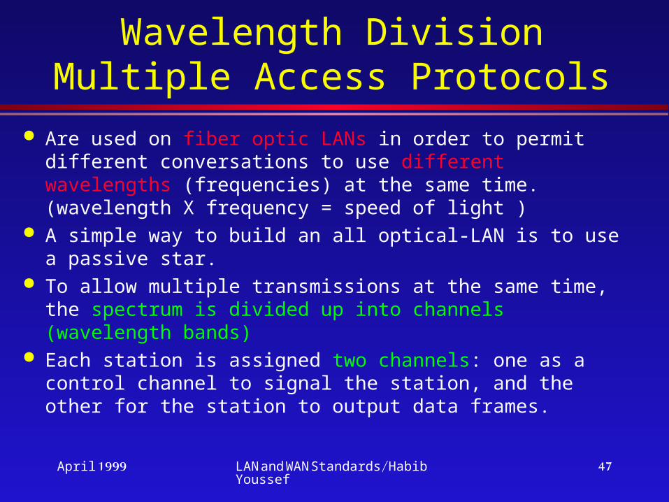
Wavelength Division Multiple Access Protocols
Are used on fiber optic LANs in order to permit different conversations to use different wavelengths (frequencies) at the same time. (wavelength X frequency = speed of light )
A simple way to build an all optical-LAN is to use a passive star.
To allow multiple transmissions at the same time, the spectrum is divided up into channels (wavelength bands)
Each station is assigned two channels: one as a control channel to signal the station, and the other for the station to output data frames.
April 1999 LAN and WAN Standards/Habib Youssef
48
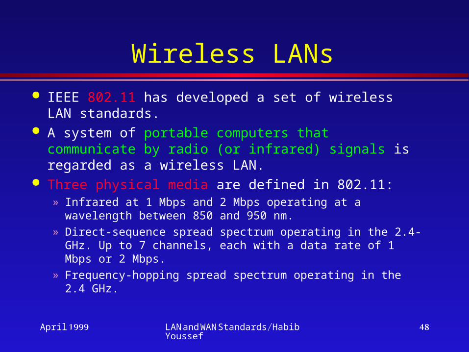
Wireless LANs IEEE 802.11 has developed a set of wireless LAN
standards. A system of portable computers that communicate
by radio (or infrared) signals is regarded as a wireless LAN.
Three physical media are defined in 802.11:» Infrared at 1 Mbps and 2 Mbps operating at a wavelength
between 850 and 950 nm.» Direct-sequence spread spectrum operating in the 2.4-GHz.
Up to 7 channels, each with a data rate of 1 Mbps or 2 Mbps.» Frequency-hopping spread spectrum operating in the 2.4
GHz.

April 1999 LAN and WAN Standards/Habib Youssef
49
Wireless LANs (cont) IEEE 802.11: CSMA/CA (CSMA with collision
avoidance).» Sender to stimulate the receiver into outputting a
short frame, so stations nearby can detect this transmission and avoid transmitting themselves for the upcoming large data frame. Sender sends an RTS (Request To Send) frame. Receiver replies with a CTS (Clear To Send) frame.
» An ACK frame is sent after each successful data frame.
» Binary exponential backoff algorithm is used if a transmitter does not hear anything from receiver.

April 1999 LAN and WAN Standards/Habib Youssef
50
Wide Area Networks(WANs)

April 1999 LAN and WAN Standards/Habib Youssef
51
WANs
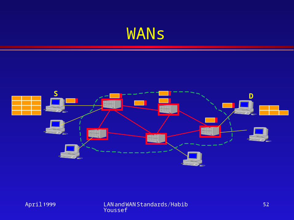
WANs cover a large geographical area.
To make optimum use of expensive communication links, WANs are structured with irregular placement of the nodes. Store-and-Forward packet switching is used to deliver packets to their destination.
April 1999 LAN and WAN Standards/Habib Youssef
52
WANs
S D
April 1999 LAN and WAN Standards/Habib Youssef
53
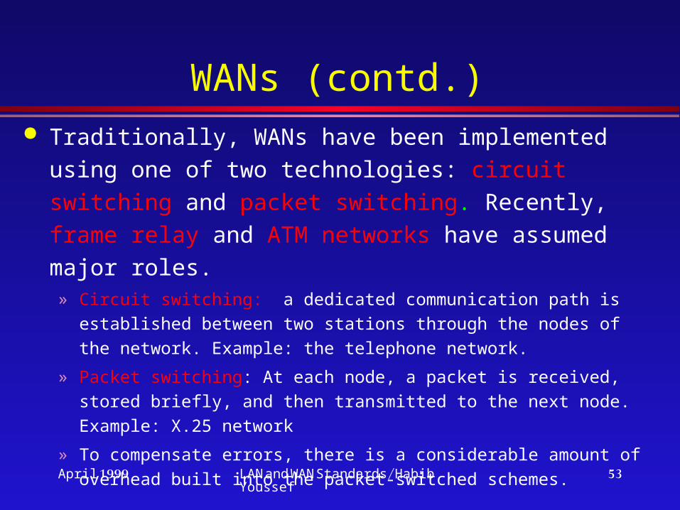
WANs (contd.) Traditionally, WANs have been implemented using
one of two technologies: circuit switching and packet switching. Recently, frame relay and ATM networks have assumed major roles.» Circuit switching: a dedicated communication path is established
between two stations through the nodes of the network. Example: the telephone network.
» Packet switching: At each node, a packet is received, stored briefly, and then transmitted to the next node. Example: X.25 network
» To compensate errors, there is a considerable amount of overhead built into the packet-switched schemes.

April 1999 LAN and WAN Standards/Habib Youssef
54
Packet and Circuit switchingS DStore Forward
S DSwitch Switch

April 1999 LAN and WAN Standards/Habib Youssef
55
WAN Communication Technologies
WANs are deployed over the existingtelecommunications infrastructure usingtechnologies such as:
» Leased line services.» Switched services.» Packet services.» Cell-based services.» Shared-media services.

April 1999 LAN and WAN Standards/Habib Youssef
56
Leased-line services
Leased lines are digital or analog telephone lines dedicated exclusively to the use of the lessee.» T1: 24 multiplexed channels at 64 Kbps each.» E1: 30 multiplexed channels at 64 Kbps each.» T2: multiplexes 4 T1 data streams.» T3: carries 672 multiplexed channels.» Fractional T1 services.

April 1999 LAN and WAN Standards/Habib Youssef
57
Switched Services
Switched services are dial-up point-to-point communication lines through the PSTN.
End station should communicate at the same speed.
Examples:» Modems.» Switched 56 Kbps service (CSU/DSU).» Switched ISDN.
April 1999 LAN and WAN Standards/Habib Youssef
58
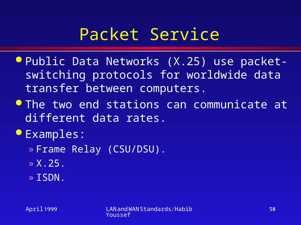
Packet Service Public Data Networks (X.25) use packet-
switching protocols for worldwide data transfer between computers.
The two end stations can communicate at different data rates.
Examples:» Frame Relay (CSU/DSU).» X.25.» ISDN.
April 1999 LAN and WAN Standards/Habib Youssef
59
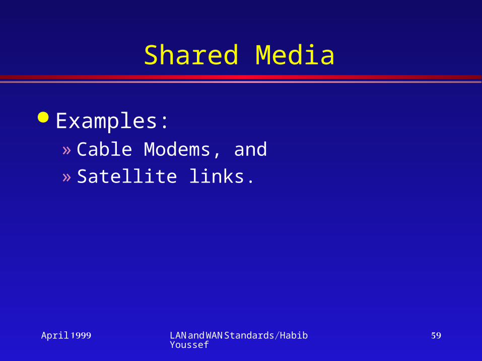
Shared Media
Examples:» Cable Modems, and» Satellite links.

April 1999 LAN and WAN Standards/Habib Youssef
60
PPP Protocol
Point-to-point protocol provides physical layer and Data Link Layer functionality.
PPP provides the following features:» Simultaneous support for multiple
protocols on the same link.» Dynamic IP addressing.» Error control.
April 1999 LAN and WAN Standards/Habib Youssef
61
DCE/DTE Interfaces
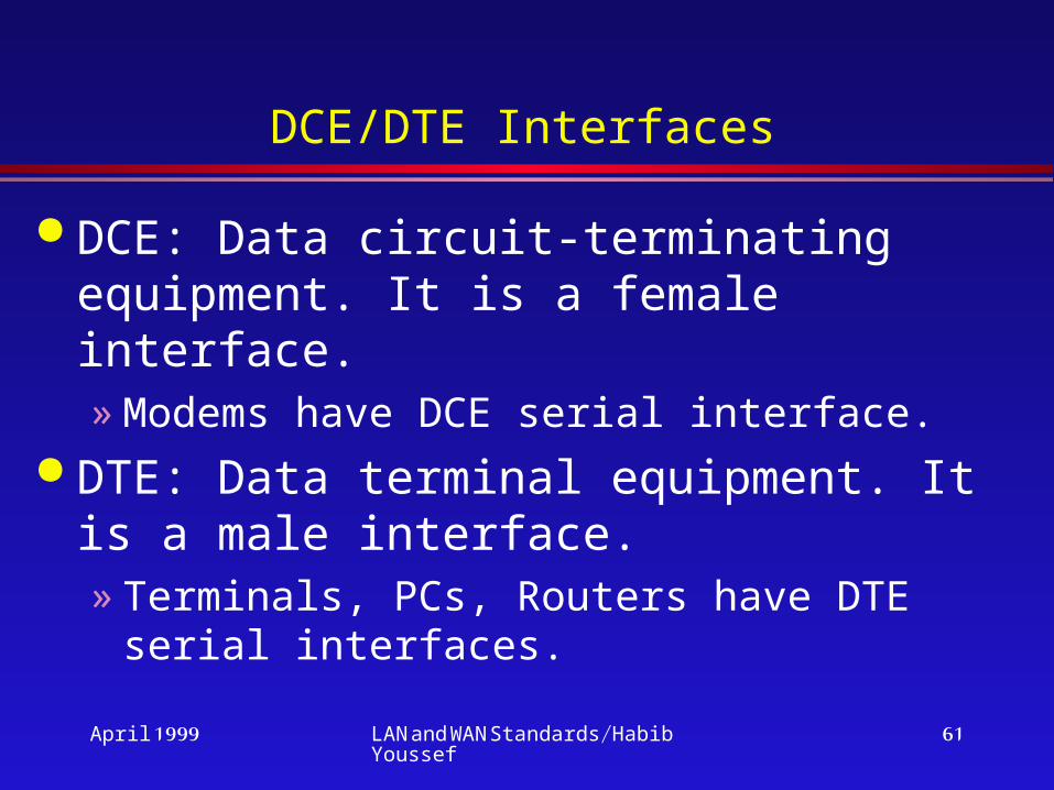
DCE: Data circuit-terminating equipment. It is a female interface. » Modems have DCE serial interface.
DTE: Data terminal equipment. It is a male interface. » Terminals, PCs, Routers have DTE serial
interfaces.
April 1999 LAN and WAN Standards/Habib Youssef
62
Communication over a Dial-up Connection
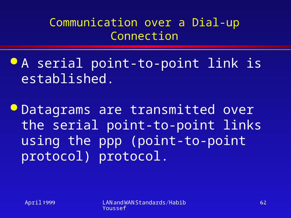
A serial point-to-point link is established.
Datagrams are transmitted over the serial point-to-point links using the ppp (point-to-point protocol) protocol.
April 1999 LAN and WAN Standards/Habib Youssef
63
PPP Frame Format
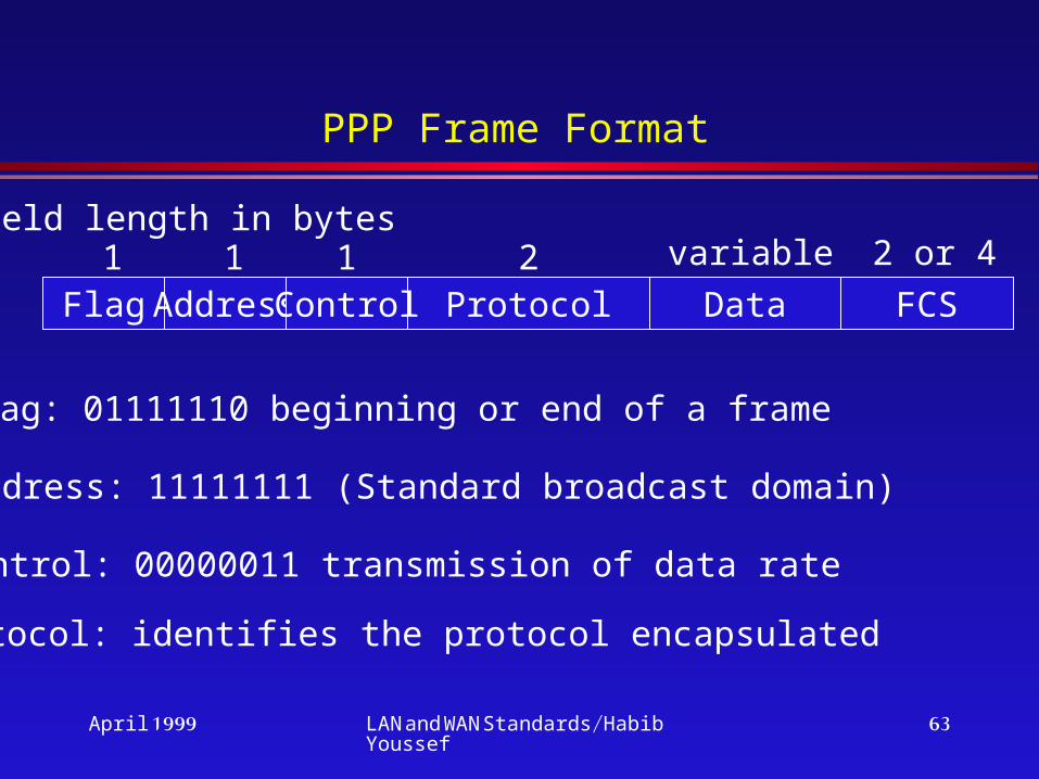
Flag Address ProtocolControl Data FCS
Field length in bytes1 1 1 2 variable 2 or 4
Flag: 01111110 beginning or end of a frame
Address: 11111111 (Standard broadcast domain)
Control: 00000011 transmission of data rate
Protocol: identifies the protocol encapsulated

April 1999 LAN and WAN Standards/Habib Youssef
64
Establishment of communications over a point-to-point link
A physical link is established. Install ppp encapsulation. PPP sends LCP (Link Control Protocol) packets
to configure the data link. PPP sends NCP (Network Control Protocol)
packets to configure network layer protocols. Datagrams from each network-layer protocol
can be sent over the link.

April 1999 LAN and WAN Standards/Habib Youssef
65
X.25 Networks Was developed during 1970s by CCITT to provide an
interface between public packet-switched networks and their customers. X.25 calls for three layers of
functionality: physical layer, data link layer, and packet (or network) layer.
The physical layer protocol, called X.21, specifies the
physical, electrical, and procedural interface between the host and the network.
Very few public networks actually support this standard. It requires digital, rather than analog signaling on the telephone lines.
April 1999 LAN and WAN Standards/Habib Youssef
66
X.25 Networks (contd) The data link layer protocol deals with transmission errors on
the telephone line between the user’s equipment (host or terminal) and the public network (router).
The network layer protocol deals with addressing, flow control, delivery confirmation, interrupts, and related issues.
» Establishes virtual circuits and sends packets of up to 128 bytes on them. These packets are delivered reliably in order.
» Most X.25 networks work at speeds up to 64 kbps
Both data link layer and network layer include flow control and error control mechanisms.

April 1999 LAN and WAN Standards/Habib Youssef
67
X.25 Networks (contd) X.25 is connection-oriented. At network layer, X.25 provides
multiplexing: a DTE is allowed to establish up to 4095
simultaneous virtual circuits with other DTEs over a single
physical DTE-DCE link.
X.25 supports both switched virtual circuits and permanent ones.
A switched virtual circuit is created when one computer sends a
packet to the network asking to make a call to a remote
computer.
» Once established, packets are sent over the connection,
always arriving in order.
» X.25 provides flow control, to make sure a fast sender cannot
swamp a slow or busy receiver.

April 1999 LAN and WAN Standards/Habib Youssef
68
X.25 Networks (contd) A permanent virtual circuit
» is used the same way as a switched one, but it is set up in advance by agreement between the customer and the carrier.
» It is always present, and no call setup is required to use it. It is analogous to a leased line.
If the user terminal does not speak X.25, then the terminal is connected to a “black box” called a PAD (Packet Assembler Disassembler) whose function is defined in the document X.3.» The protocol X.28 is defined between terminal and PAD.
» The protocol X.29 is defined between PAD and the network.
April 1999 LAN and WAN Standards/Habib Youssef
69
WANs (cont) Frame relay was developed to take advantage of
high data rates and low error rates that are available in modern high-speed communication systems. It operates efficiently at user data rates up to 2 Mbps. It uses variable-length packets, called frames.
ISDN is intended to be a worldwide public telecommunications network to replace existing public telecommunications networks and deliver a wide variety of services.
» Narrowband ISDN» Broadband ISDN (B-ISDN)

April 1999 LAN and WAN Standards/Habib Youssef
70
WANs (cont)
ATM (Asynchronous Transfer Mode) : » Is a culmination of all of the developments in
circuit switching and packet switching.
» Can be viewed as an evolution from frame relay. ATM uses fixed-length packets, called cells.
April 1999 LAN and WAN Standards/Habib Youssef
71
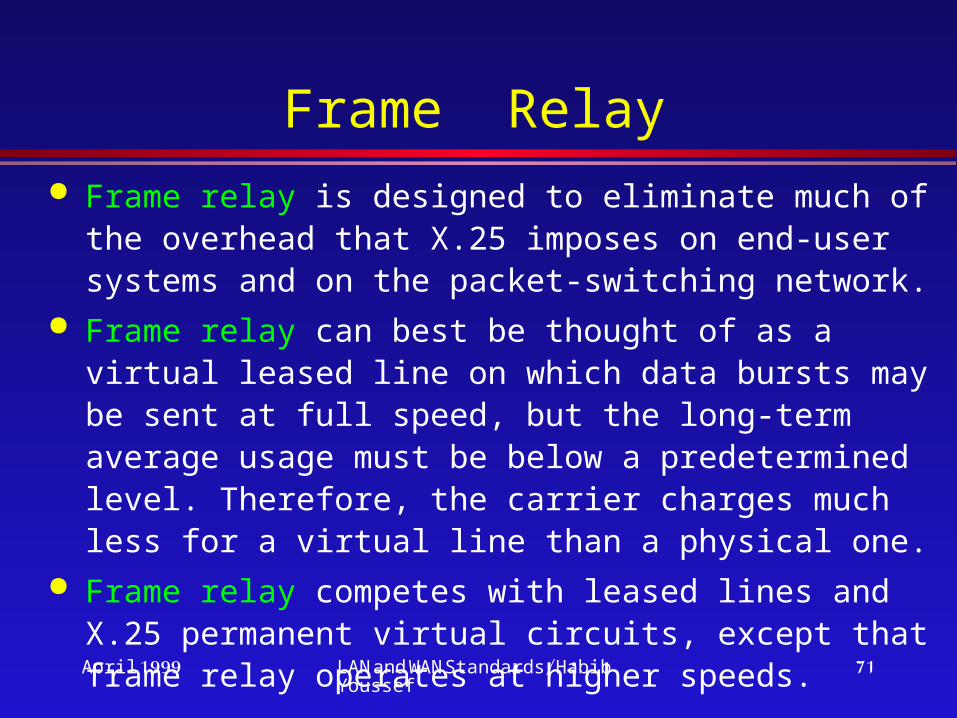
Frame Relay Frame relay is designed to eliminate much of the
overhead that X.25 imposes on end-user systems and on the packet-switching network.
Frame relay can best be thought of as a virtual leased line on which data bursts may be sent at full speed, but the long-term average usage must be below a predetermined level. Therefore, the carrier charges much less for a virtual line than a physical one.
Frame relay competes with leased lines and X.25 permanent virtual circuits, except that frame relay operates at higher speeds.

April 1999 LAN and WAN Standards/Habib Youssef
72
Frame Relay (cont.)
Frame Relay offers data transfer rates from 56 Kbps to T1 or E1 speed.
Frame Relay networks are used to interconnect individual LANs into a WAN.
A CSU/DSU provides the interface between the subscriber’s computer equipment and the telephone line.

April 1999 LAN and WAN Standards/Habib Youssef
73
Frame Relay (contd) The principal disadvantage of frame relay, compared to X.25, is
that we lost the ability to do link-by-link flow and error control.
Source Destination DestinationSource
Packet-switching Frame relay
1 8
2
7
3
6
451 2 1516
34
13
145
12
6
11
7 1089

April 1999 LAN and WAN Standards/Habib Youssef
74
Frame Relay Frame Format
Flags Address Data FCS Flags
21 Variable 2 1
10 bits of the bytes Address field comprise the actual circuit ID (called the DLCI, for “data link connection identifier”.)

April 1999 LAN and WAN Standards/Habib Youssef
75
ISDN, B-ISDN, and ATM Telephone companies are faced with a fundamental
problem: maintaining multiple networks. Also, want to control cable television network
The solution was to invent a single new network that will replace the entire telephone system and all the specialized networks.
The new wide area service is first called ISDN (Integrated Services Digital Network) that has as its primary goal the integration of voice and nonvoice services.

April 1999 LAN and WAN Standards/Habib Youssef
76
Narrow Band-ISDN
The ISDN bit pipe supports multiple channels interleaved by time division multiplexing. Several channel types have been standardized:
» A: 4-kHz analog telephone channel
» B: 64-kbps digital PCM channel for voice or data
» C: 8-kbps or 16-kbps digital channel
» D: 16-kbps digital channel for out-of-band signaling
» E: 64-kbps digital channel for internal ISDN signaling
» H: 384-kbps, 1536-kbps, or 1920-kbps digital channel
Three combinations of channels:» Basic rate: 2B+1D » Primary rate: (1) 23B+1D (U.S. and Japan), (2) 30B+1D
(Europe)» Hybrid: 1A+1C

April 1999 LAN and WAN Standards/Habib Youssef
77
B-ISDN and ATM
B-ISDN offers video on demand, live television from many sources, full motion multimedia electronic mail, CD-quality music, LAN interconnection, high-speed data transfer.
The transfer mode of B-ISDN ATM (Asynchronous Transfer Mode).
ATM is the standard technology for switching and multiplexing in B-ISDN.

April 1999 LAN and WAN Standards/Habib Youssef
78
How ATM Works?
Data Units: Fixed-length cells of size 53 bytes each (5 Header + 48 payload).
Operates at the equivalent of MAC sublayer. Operates above physical layer which could be SONET, Fibre channel,...
Connection-oriented. Layered architecture.

April 1999 LAN and WAN Standards/Habib Youssef
79
ATM Layered Architecture
Higher LayersUser Services & applications
ATM Adaptation Layer
ATM Layer
Physical MediumDependent Layer
Fragmentation andde-fragmentation of frames
Cell header insertion/removalCell relaying & multiplexingConnection establishment
Transmission & receipt of bitsSynchronization

April 1999 LAN and WAN Standards/Habib Youssef
80
How ATM Works?
Data packet
AAL
ATM
Physical Layer

April 1999 LAN and WAN Standards/Habib Youssef
81
How ATM Works (Contd.)?
Physical Layer
Entire process is reversed
Overhead
Envelope
Cell
April 1999 LAN and WAN Standards/Habib Youssef
82
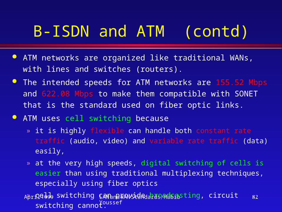
B-ISDN and ATM (contd) ATM networks are organized like traditional WANs, with lines
and switches (routers).
The intended speeds for ATM networks are 155.52 Mbps and 622.08 Mbps to make them compatible with SONET that is the standard used on fiber optic links.
ATM uses cell switching because
» it is highly flexible can handle both constant rate traffic (audio, video) and variable rate traffic (data) easily,
» at the very high speeds, digital switching of cells is easier than using traditional multiplexing techniques, especially using fiber optics
» cell switching can provide broadcasting, circuit switching cannot.

April 1999 LAN and WAN Standards/Habib Youssef
83
ATM Backbone
Tower box
Tower box
ATM-Attached Servers
ATM Backbone
Workstation
Workstation
Workstation
ATM- Attached
Client
LAN Attached Clients
April 1999 LAN and WAN Standards/Habib Youssef
84
Internet Is a large collection of interconnected networks, all of
which use TCP/IP protocol suite
Began with the development of ARPANET in 1969
(ARPA: Advanced Research Project Agency)
ARPANET protocols were not suitable for running over multiple networks. This led to the invention of the TCP/IP model and protocols by Cerf and Kahn in 1974.
TCP/IP became the only official protocol on Jan. 1, 1983. The glue that holds the Internet together is the TCP/IP protocol stack.
April 1999 LAN and WAN Standards/Habib Youssef
85
Internet (contd) A machine is on the Internet if it runs the TCP/IP
protocol stack, has an IP address, and can send IP packets to any machine on the Internet.
Until the early 1990s, Internet users were academic, industrial, and government researchers. But, WWW (World Wide Web) brought millions of nonacademic users.
WWW made the underlying facilities of the Internet easier to use.