Embed Size (px)
Citation preview

April 18, 2023
The NS7520

2
NET+ARM
ARM7TDMIProgrammer’s Model

3
Processor Operating States
• The ARM7TDMI can be in one of two Processor Operating States:
- ARM state which executes 32-bit, word-aligned ARM instructions- Thumb state which operates with 16-bit, halfword-aligned Thumb instructions.
Note: Transition between these two states does notaffect the operating mode (user, supervisor, …) or the contents of the registers

4
Switching between OP States
• Entering Thumb state:- Execute a BX instruction with the state bit (bit 0) set in the operand register- Transition also occurs automatically when returning from an exception if this was entered with the processor in Thumb state
• Entering ARM state- Execute a BX instruction with the state bit clear in the operand register- Also occurs on the processor taking an exception (IRQ, FIQ, RESET, UNDEF, ABORT, SWI, etc.)
BX = Branch and Exchange (Operating State)

5
Memory Formats
• ARM7TDMI views memory as a linear collection of bytes numbered upwards from zero.
• Bytes 0 to 3 hold the first word, bytes 4 to 7 the second and so on.
• The ARM7TDMI can treat words in memory as being stored either in - Big Endian format (also known as Motorola format)- Little Endian format (also known as Intel format)
6
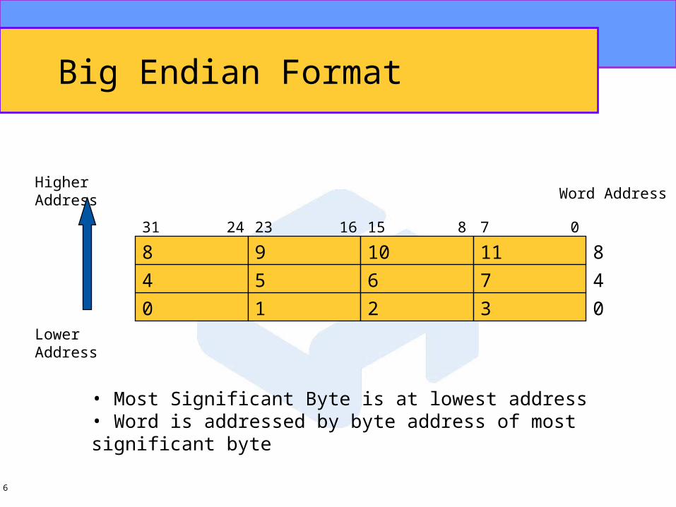
Big Endian Format
0 1 2 3 0
4 5 6 7 4
8 9 10 11 8
0781516232431
Word Address
Lower Address
Higher Address
• Most Significant Byte is at lowest address• Word is addressed by byte address of most significant byte
7
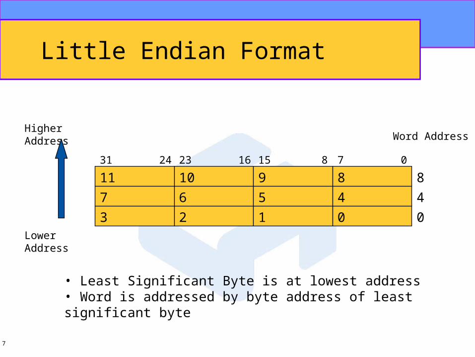
Little Endian Format
3 2 1 0 0
7 6 5 4 4
11 10 9 8 8
0781516232431
Word Address
Lower Address
Higher Address
• Least Significant Byte is at lowest address• Word is addressed by byte address of least significant byte

8
Instruction Length and Data Types
• ARM7TDMI Instruction Length is- 32 bits in ARM state- 16 bit in Thumb state
• ARM7TDMI supported datatypes are:- byte (8-bit)- halfword (16-bit)- word (32-bit)
• Words must be aligned to four-byte boundaries and halfwords at two-byte boundaries

9
ARM7TDMI Registers
• ARM7TDMI has a total of 37 registers- 31 general purpose 32-bit registers- 6 status registers
• Not all registers can be seen at once!
• The processor state and operating mode dictate which registers are available to the programmer

10
ARM State Register Set
• 16 general registers and one or two status registers are visible at one time
• Mode-specific banked registers are switched inin privileged, non-User modes
• Dedicated registers are:- R14 receives a copy of R15 when a Branch with Link instruction (BL) is executed.- R15 holds the Program Counter- R16 is the CPSR (Current Program Status Register) This contains the condition code flags and the current mode bits.

11
ARM State Register Set
R0
R1
R2
R3
R4
R5
R6
R7
R8
R9
R10
R11
R12
SP
LR
PC
CPSR
R0
R1
R2
R3
R4
R5
R6
R7
R8_fiq
R9_fiq
R10_fiq
R11_fiq
R12_fiq
SP_fiq
LR_fiq
PC
CPSR
R0
R1
R2
R3
R4
R5
R6
R7
R8
R9
R10
R11
R12
SP_svc
LR_svc
PC
CPSR
R0
R1
R2
R3
R4
R5
R6
R7
R8
R9
R10
R11
R12
SP_abt
LR_abt
PC
CPSR
R0
R1
R2
R3
R4
R5
R6
R7
R8
R9
R10
R11
R12
SP_irq
LR_irq
PC
CPSR
R0
R1
R2
R3
R4
R5
R6
R7
R8
R9
R10
R11
R12
SP_und
LR_und
PC
CPSR
SPSR_fiq SPSR_svc SPSR_abt SPSR_irq SPSR_und
System & User FIQ Supervisor Abort IRQ Undefined
Banked Registers

12
Thumb State Register Set
R0
R1
R2
R3
R4
R5
R6
R7
PC
CPSR
R0
R1
R2
R3
R4
R5
R6
R7
PC
CPSR
R0
R1
R2
R3
R4
R5
R6
R7
CPSR
R0
R1
R2
R3
R4
R5
R6
R7
CPSR
R0
R1
R2
R3
R4
R5
R6
R7
CPSR
R0
R1
R2
R3
R4
R5
R6
R7
CPSR
SPSR_fiq SPSR_svc SPSR_abt SPSR_irq SPSR_und
System & User FIQ Supervisor Abort IRQ Undefined
SP
LR
SP_fiq
LR_fiq
SP_svc
LR_svc
SP_abt
LR_abt
SP_irq
LR_irq
SP_und
LR_und
PC PC PC PC
Banked Registers

13
State Switching
R0
R1
R2
R3
R4
R5
R6
R7
Stack Pointer (SP)
Link Register (LR)
Program Counter (PC)
CPSR
SPSR
Thumb State
R0
R1
R2
R3
R4
R5
R6
R7
R8
R9
R10
R11
R12
Stack Pointer (SP)
Link Register (LR)
Program Counter (PC)
CPSR
SPSR
ARM State
14
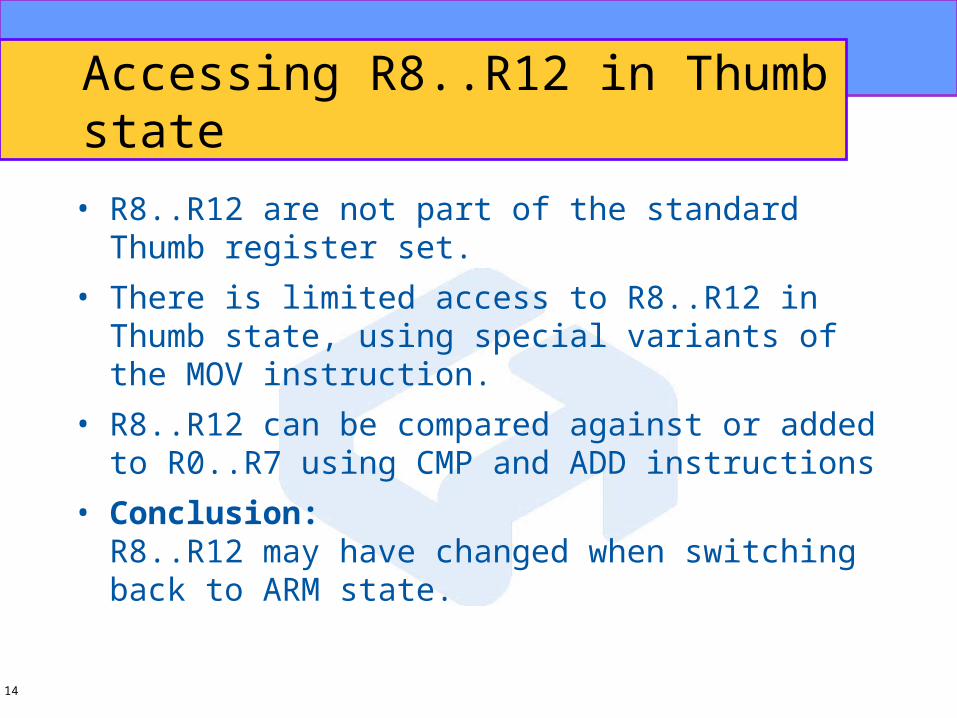
Accessing R8..R12 in Thumb state
• R8..R12 are not part of the standard Thumb register set.
• There is limited access to R8..R12 in Thumb state, using special variants of the MOV instruction.
• R8..R12 can be compared against or added to R0..R7 using CMP and ADD instructions
• Conclusion:R8..R12 may have changed when switching back to ARM state.

15
The Program Status Registers
• The ARM7TDMI contains a Current Program Status Register (CPSR), plus five Saved Program Status Registers (SPSR). These- hold Information about the most recently performed ALU operation- control the enabling and disabling of Interrupts- set the Processor operating mode
N
31
Z
30
C
29
V
28
.
27
.
26
.
8
I
7
F
6
T
5
M4
4
M3
3
M2
2
M1
1
M0
0
OverflowCarry/BoorowZeroNegative
ModeStateFIQ disableIRQ disable
Control BitsreservedCondition Code

16
Condition Codes
• N, Z, C and V bits are the condition code flags.These may be changed as a result of arithmetic and logical operations and may be tested to determine whether an instruction should be executed.
• In ARM state a l l instructions may be executed conditionally
• In Thumb state, only the Branch instruction is capable of conditional execution

17
Control Bits
• The T-bitReflects the operating state and is set when in Thumb
• The Interrupt disable bitsAre used to mask (disable) the IRQ and FIQ interrupts
• The mode bitsM4..M0 determine the operating mode. Not all combinations define a valid operating mode – Illegal values programmed into the mode bits will cause the processor enter an unrecoverable state. If this happens, a reset should be applied.
• Reserved bitsShould never be altered.

18
Operating Mode Summary
M4:M0 Mode Visible Thumb state registers
Visisble ARM state registers
0b10000 User R7..R0
LR, SP
PC, CPSR
R14..R0
PC, CPSR
0b10001 FIQ R7..R0
LR_fiq, SP_fiq
PC, CPSR, SPSR_fiq
R7..R0
R14_fiq..R8_fiq
PC, CPSR, SPSR_fiq
0b10010 IRQ R7..R0
LR_irq, SP_irq
PC, CPSR, SPSR_irq
R12..R0
R14_irq..R13_irq
PC, CPSR, SPSR_irq
0b10011 Supervisor R7..R0
LR_svc, SP_svc
PC, CPSR, SPSR_svc
R12..R0
R14_svc..R13_svc
PC, CPSR, SPSR_svc
0b10111 Abort R7..R0
LR_abt, SP_abt
PC, CPSR, SPSR_abt
R12..R0
R14_abt..R13_abt
PC, CPSR, SPSR_abt
0b11011 Undefined R7..R0
LR_und, SP_und
PC, CPSR, SPSR_und
R12..R0
R14_und..R13_und
PC, CPSR, SPSR_und
0b11111 System R7..R0
LR, SP
PC, CPSR
R14..R0
PC, CPSR

19
Exceptions (1)
• Actions on entering an exception- Save return address in the appropriate LR Return address is either current PC + 4 or current PC +8 (depending on the exception)- Copy the CPSR into the appropriate SPSR- Force the CPSR mode bits to a value which depends on the exception- Load PC to fetch next instruction from the relevant exception vector
Note: If the processor is in Thumb state when an exception occurs, it will automatically switch into ARM state when the PC is loaded with the exception vector address.

20
ARM State Register Set
R0
R1
R2
R3
R4
R5
R6
R7
R8
R9
R10
R11
R12
SP
LR
PC
CPSR
R0
R1
R2
R3
R4
R5
R6
R7
R8_fiq
R9_fiq
R10_fiq
R11_fiq
R12_fiq
SP_fiq
LR_fiq
PC
CPSR
R0
R1
R2
R3
R4
R5
R6
R7
R8
R9
R10
R11
R12
SP_svc
LR_svc
PC
CPSR
R0
R1
R2
R3
R4
R5
R6
R7
R8
R9
R10
R11
R12
SP_abt
LR_abt
PC
CPSR
R0
R1
R2
R3
R4
R5
R6
R7
R8
R9
R10
R11
R12
SP_irq
LR_irq
PC
CPSR
R0
R1
R2
R3
R4
R5
R6
R7
R8
R9
R10
R11
R12
SP_und
LR_und
PC
CPSR
SPSR_fiq SPSR_svc SPSR_abt SPSR_irq SPSR_und
System & User FIQ Supervisor Abort IRQ Undefined
Banked Registers
Saved CPSR
CPSRCPSR
PCPC
Saved PC
CPSR
PC
21
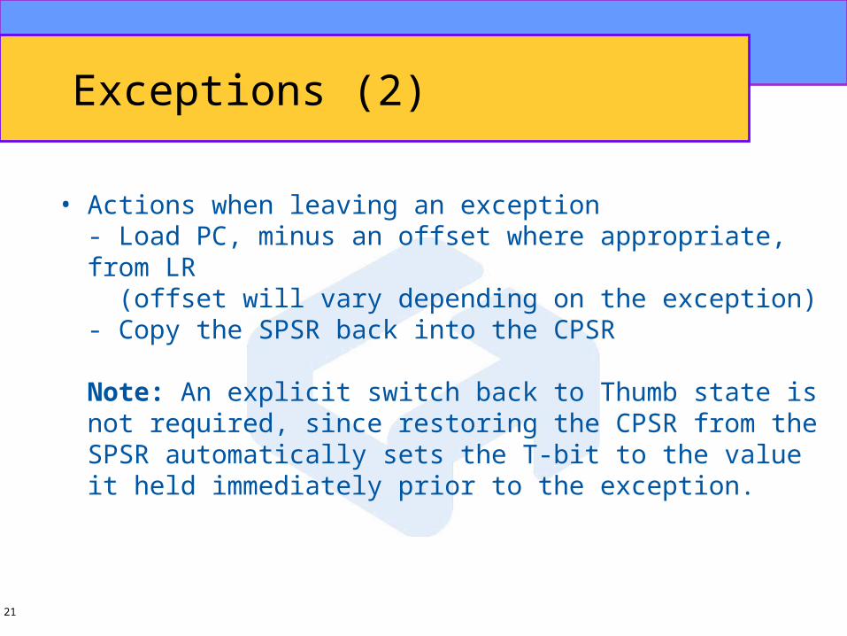
Exceptions (2)
• Actions when leaving an exception- Load PC, minus an offset where appropriate, from LR (offset will vary depending on the exception)- Copy the SPSR back into the CPSR
Note: An explicit switch back to Thumb state is not required, since restoring the CPSR from the SPSR automatically sets the T-bit to the value it held immediately prior to the exception.

22
Exception entry/exit Summary
Return Instruction Previous State
ARM R14_x Thumb R14_x
BL MOV PC,R14 PC+4 PC+2
SWI MOVS PC, R14_svc PC+4 PC+2
UNDEF MOVS PC, R14_und PC+4 PC+2
FIQ SUBS PC, R14_fiq, #4 PC+4 PC+4
IRQ SUBS PC, R14_irq, #4 PC+4 PC+4
PABT SUBS PC, R14_abt, #4 PC+4 PC+4
DABT SUBS PC, R14_abt, #8 PC+8 PC+8
RESET NA - -

23
Exception Vectors and Priority
Address Exception Mode on entry Priority
0x0 Reset PC+4 1
0x4 Undefined Instruction PC+4 6*
0x8 Software Interrupt PC+4 6*
0xc Prefetch Abort PC+4 5
0x10 Data Abort PC+4 2
0x14 reserved PC+4 NA
0x18 IRQ PC+8 4
0x1c FIQ - 3
Note: Undefined Instruction and Software Interrupt are mutually exclusive, since they each correspond to particular (non-overlapping) decodingsof the current instruction.

24
Interrupt Latencies
TD = Tsyncmax + Tldm + Tfiq
Tsyncmax is 5 clock cyclesTldm is the time for the longest instruction to
complete (which is the LDM instruction)and is 23 cycles
Tfiq is the time for the FIQ entry and is 2 clock cycles
@44 MHz this will give a total of 30 clocks (less than 1us) for the processor to execute the FIQInstruction at address 0x1c.

25
Q & A