Embed Size (px)
Citation preview

Approximating Mathematical Surfaces with Spline Modelers
Stephen Luecking
School of Computer Science, Telecommunications and Information Systems
DePaul University
243 South Wabash
Chicago, IL 60604
Abstract
Computer modeling permits the creation and editing of mathematical surfaces with only an intuitive understanding of such forms. B-splines used in most commercial modeling packages permit the approximation of a wide variety of mathematical surfaces. Such programs may contain tools for aiding in the production of these surfaces as physical sculptures. We outline some techniques for non-mathematical designers and sculptors to produce these objects with conventional modeling.
Mathematical sculptures are premised on the inherent beauty discovered again and again in mathematical
objects. Among the most elegant and bewitching of these objects are the multitudes of surfaces that twine
through 3D and 4D spaces. In industry-standard programs, intended for the designer and not the
mathematician, no equations or formulations exist to generate such forms; rather they employ a general, all-purpose geometry for fashioning 3D objects from the designer’s vision.
This geometry is the “material” of 3D graphics, specifically geometry that is computable. Surfaces are commonly computed by defining the surface with points in a coordinate space. The surface results from
one of two methods of interpolation among these points: one method treats the points as vertices of
polygons; the other uses a fabric of spline curves, known as B-splines, that pass through these points. The
former is familiar to users of the Mathematica software and the latter to computer artists and designers seeking more natural representations of design products, characters, and scenes. Since both cases require
interpolation, the results are approximate, although close enough in practice for almost all applications.
What the computer produces, then, are representations or models of the surface.
In the hands of most artists, computer modeling is not at all mathematical, even though the artists are
manipulating geometry at all stages. The user interfaces of all popular modeling programs work at making this manipulation intuitive and as close to drawing and design traditions as possible. Nevertheless, the
best of these programs also boast ample tools for the mathematically inclined artist to build surfaces
expressing mathematical elegance. Because such models are always approximations used to represent a
surface they are closer to well-crafted plaster carvings, formed metal, or string models of surfaces than they are to the actual mathematical surface.
Developable Surfaces
Most modeler’s represent ruled surfaces by sweeping straight lines through space. Many ruled surfaces
are developable and can be crafted from sheet materials, as is the case of Naum Gabo’s sculpture, “Spheric Theme” (Figure 2). Gabo disavowed the mathematical nature of his work and avowed, instead,
that his surfaces were the natural outcome of experimentation with sheet metal’s ease in fashioning
developable surfaces. “Spheric Theme” originated, for example, from the joining of two split annuli cut from paper and joined at their split edges into one continuous surface. There is a mathematical spirit to
473

such experiments, even if mathematics was never consciously a part of the process. The fact that the
sweeping arcs of Gabo’s sculpture began as flat sheets of bronze qualifies it as a developable surface. By definition a developable surface can be mapped – or unrolled – to a flat surface with no discernible
distortions or projections.
Figure 1 Joe DiMaggio autographed baseball. Figure 2 Naum Gabo, “Spheric Theme”
a b c d
Figure 3a-c Developing surface in a sphere 3d Stitched polysurface Like the symmetry of a baseball’s seam, Gabo’s surface was the result of minimally crafting a sphere in
space. Procuring form in a modeling program often follows such mathematically-spirited crafting rather
than calculations and formulas. The bottom sequence in Figure 3 demonstrates such an approach. It begins with the intersection of a sphere and a cube whose edges are tangent to the sphere (Figure 3a).
From the six tangent circles that ensue, four semi-circles join into a single curve dividing the surface of
the sphere (Figure 3b). A smaller version of this curve is copied to the center to act as a second rail along which to sweep a surface (Figure 3c). The modeler affixes this surface to one half of the divided sphere
and another surface segment at the center (Figure 3d).
Booleans and Surfaces Once all of the surfaces have been stitched into a closed polysurface, the program treats it as a solid and it
then becomes subject to Boolean edits. The Boolean operations – union, difference and intersection –
allow surface models to imitate the edits of constructive solid geometry (CSG).
When two closed polysurfaces interpenetrate they can affect one another’s shape by applying the Boolean
operations. Union (Figure 4a) trims those surface portions enclosed within the penetration. The exterior
surfaces remain to represent a single solid. Difference (Figure 4b) rejects the exterior surface segment of one shape and the enclosed surface segment of the other. The remainder appears as a solid with an
extraction shaped like the subtracted solid. Intersection (Figure 4c) retains the interior surface segments
while discarding the exterior. The new solid includes only that region of space common to both solids.
The polysurfaces created by a Boolean operation always comprise portions of at least two surfaces.
474

UNION DIFFERENCE INTERSECTION
a b c
Figure 4 Boolean operations.
Figure 5 Previous polysurface with spherical concavities. Figure 6a Orthogonally intersecting cylinders.
Figure 6b Boolean intersection of three cylinders.
In most design modelers, CSG modeling relies on sets of geometric primitives. The primitives are a set of
commonly used geometric solids that the designer can quickly and easily insert into the modeling space. These may include boxes, cones, cylinders, spheres, toruses, ellipsoids and paraboloids. The last three
provide a stock of ready-made quadratic surfaces, the spheroids. Other related, but less-used surfaces like
the hyperboloid below can generate easily in a spline environment.
Geometric “Grain”
Gaspard Monge invented string models to instruct his students on the nature of ruled surfaces. One of the
best known is the hyperboloid, depicted in Figure 7a as model by Theodore Olivier, one of Monge’s most famous students. This model begins as a string model of a cylinder. The top circle then rotates to skew the
475

string lines to form the hyperboloid. This can be generated by sweeping a straight line, thereby creating
the effect of a series of canted strings connecting two end circles (Figure 7b,c). The same form may also be treated as a surface of revolution, created by revolving a hyperbola around an axis. Each method of
construction will yield the same shape, but with differing internal geometry. Different geometries will
have a significant effect on how the surface may be edited or manufactured.
a b c
d e
Figure 7a String hyperboloid. b,c Ruled sweeping of the hyperboloid. d Sliced hyperboloid. e Folded hyperboloid.
Much as the grain of a chosen material affects the crafting of objects from that material, so the fabric of
the geometry used to craft a model determines much of the disposition of the model. According to the program’s build geometry, the ruled version of the hyperboloid can unroll into a pattern, while the
revolved version cannot unroll. This can mislead, since a prompt from the program also cautions that the
unrolled surface pictured is 25% larger in area than the original surface. In truth the hyperboloid will not
unroll, however, the program treats any ruled surface as developable.
The program recognizes that the revolved surface possesses double curvature: the hyperbola begins as a
curve and revolves in a circle, yielding the second curve. This can be replicated through a structure of cross-sections (Figure 7d). The cross-sectional structure has the added benefit of providing an extremely
strong armature for a sculpture. Crafted in thin plywood and filled with conventional auto body repair
putty, a sculpture of great durability and permanence results.
The folded version (Figure 7e) is in fact a rotationally skewed, concave anti-prism. Its pattern was crafted
by dividing the “unrolled” surface into right triangles. The 25% overage of the unrolling process
disappears into the concave folds and the convex edges follow the actual surface of the hyperboloid.
476

Minimal Surfaces
Splines were thin strips of cedar or metal that early draftsmen/shipwrights could flex into a variety of
non-circular and streamlined curves for tracing onto their design drawings. The spline would curve
according to the natural effect of stress on the material. When mathematicians developed spline geometry they assumed that the spline behaved like an extremely thin beam and adapted Euler’s formula for a
bending beam to describe spline curves. The spline surface is described by a net of such curves that
behave remarkably like sheets of highly flexible material under stress.
Spline surfaces can often take on characteristics of minimal surfaces, responding somewhat like soap
films or shrink wrap when applied to an armature of curves. The top sequence of screenshots in Figure 8
illustrates the editing of a circle into an armature for the edges of a monkey saddle surface. Instructing the program to build a patch inside the curve will cause it to seek the most efficient surface configuration
within the program’s parameters. This will sometimes yield a strong approximation of a minimum
surface, as is the case with the monkey surface, or it may yield the simplest executable construction.
a b c
d e f
Figure 8a,b editing a curve armature for the monkey saddle. c patch surface for monkey saddle.
d.e monkey saddle edited from a revolved disk e composite of cylinder and saddles
The alternative construction from a revolved disk has its net aligned in a radial pattern from a center
singularity. This version of the surface is stronger as a visual build than as a mathematical approximation. It results from a controlled hand edit of surface points rather than a solely computational execution. Its
radial grain, however, is more in keeping with the symmetry of the surface and offers the opportunity to
edit along the lines of that symmetry. The surface below is an edit of this surface with the center drawn
out and radial veining added.
477

Figure 9 floral surface from an edit of the radial monkey saddle.
The hyperbolic paraboloid is a minimal surface that, like the hyperboloid, a modeling program can generate by sweeping a straight line. Such ruled surfaces, which can be modeled with taut string, can also
be built at architectural scales with stressed steel cable. During the 1950’s architectural engineers began
applying this method to form roof shells of pre-stressed reinforced concrete – roofs whose double curvature provided strengths similar to domed roofs.
Figure 10 hyperbolic paraboloid from swept line Figure 11 Félix Candela's Iglesia de San José Obrero, Mexico.
Shell Surfaces As judged from their natural counterparts, shell surfaces are an especially beautiful category of form. The
surface is essentially a circle swept along a spiral, flat or helical. In modeling programs, the spiral options
are typically limited to Archimedean spirals, whereas natural shells configure more closely to equiangular, logarithmic, spirals. These spirals are also termed growth spirals; they possess scalar
symmetry, in which equal radial divisions of the spiral increase by a fixed ratio.
478

Fortunately, growth spirals are easily constructed from a set of regularly-spaced radials and a connected
series of perpendiculars drawn on those lines as in Figure 12 below. By increasing or decreasing the number of radials, the spiral will follow a more open or more closed path. The series of perpendiculars
will interpolate into the spiral curve that closely approximates the growth pattern of natural shells.
Constructing the actual shell surface is more difficult in practice than in theory. In almost all standard
programs, attempts to sweep a circle along the spiral are frequently thwarted, yielding unpredictable effects.
A good approach is to “flow” a conical surface along the spiral (Figure 14). This cone should have an altitude equal to the length of the curve and should be rebuilt into a net comprising a larger array of
splines to permit greater flexibility. Figure 13 illustrates rebuilding the cone’s surface geometry: cone A is
a cone as created by the modeling program and cone B is a rebuilding of that cone. The first cone is a true cone as reproduced by spline geometry; however, it has no control points to permit it to flex. A control
point carries a mathematical weight, termed its rho value, that pulls the surface splines to curve toward
that weight. Adding more control points permits finer curvature of the surface. Rebuilding adds more
surface splines and therefore more control points. The rebuilt cone is no longer a true cone, but it is an admirably sufficient approximation.
A second approach is a little more complex, but offers more control. Create a triangular section of the cone. This shape will have only three edit points, one at each vertex and so it, too, requires rebuilding in
order to smoothly flow along the spiral. The base edge of this triangular surface denotes the diameter and
the side edges serve as two rails along which to sweep the circle. A two-railed sweep (Figure 15) is usually more stable and predictable than a sweep on a single rail. Figure 16 pairs shells to mimic the snail
minimal surface. This surface is then capped by two hemispheres to create the sculpture in Figure 17.
Figure 12 Equiangular spiral. Figure 13a Original conical surface. b Cone rebuilt into editable surface.
Virtual Sculpting
Most sculptors have an intuition for form, which in another life may have steered them into mathematics.
Still, in this life, they have an appreciation for the elegance of mathematical surfaces that parallels that of the mathematician. As more and more sculptors integrate computer modeling into their tool set, the
potential for them to create satisfactory replications of these surfaces becomes more and more accessible.
By sculpting in the virtual materials of geometry, the intuition and craft of the sculptor can open up for
them a new vocabulary of visual form.
A
B
479
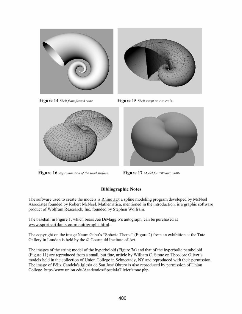
Figure 14 Shell from flowed cone. Figure 15 Shell swept on two rails.
Figure 16 Approximation of the snail surface. Figure 17 Model for “Wrap”, 2006.
Bibliographic Notes
The software used to create the models is Rhino 3D, a spline modeling program developed by McNeel Associates founded by Robert McNeel. Mathematica, mentioned in the introduction, is a graphic software
product of Wolfram Reasearch, Inc. founded by Stephen Wolfram.
The baseball in Figure 1, which bears Joe DiMaggio’s autograph, can be purchased at
www.sportsartifacts.com/ autographs.html. The copyright on the image Naum Gabo’s “Spheric Theme” (Figure 2) from an exhibition at the Tate
Gallery in London is held by the © Courtauld Institute of Art.
The images of the string model of the hyperboloid (Figure 7a) and that of the hyperbolic paraboloid (Figure 11) are reproduced from a small, but fine, article by William C. Stone on Theodore Oliver’s
models held in the collection of Union College in Schnectady, NY and reproduced with their permission.
The image of Félix Candela's Iglesia de San José Obrero is also reproduced by permission of Union College. http://www.union.edu/Academics/Special/Olivier/stone.php
480