Embed Size (px)
Citation preview
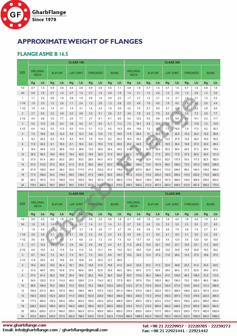
ASME FLANGES■ Approximate weight of Flanges
■ Tolerances
■ Welded and seamless pipe carbon and alloy steels
■ Welded and seamless pipe stainless steels
■ Material Specifications
■ Class 150 Flanges
■ Class 300 Flanges
■ Class 600 Flanges
■ Class 900 Flanges
■ Class 1500 Flanges
■ Class 2500 Flanges
Gharb Flange

Rev. 3. 0 / 2014. 10. 01FLANGES - 8
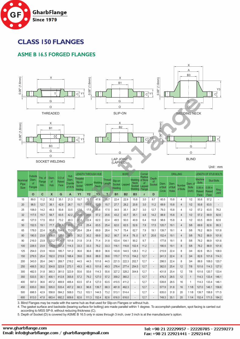
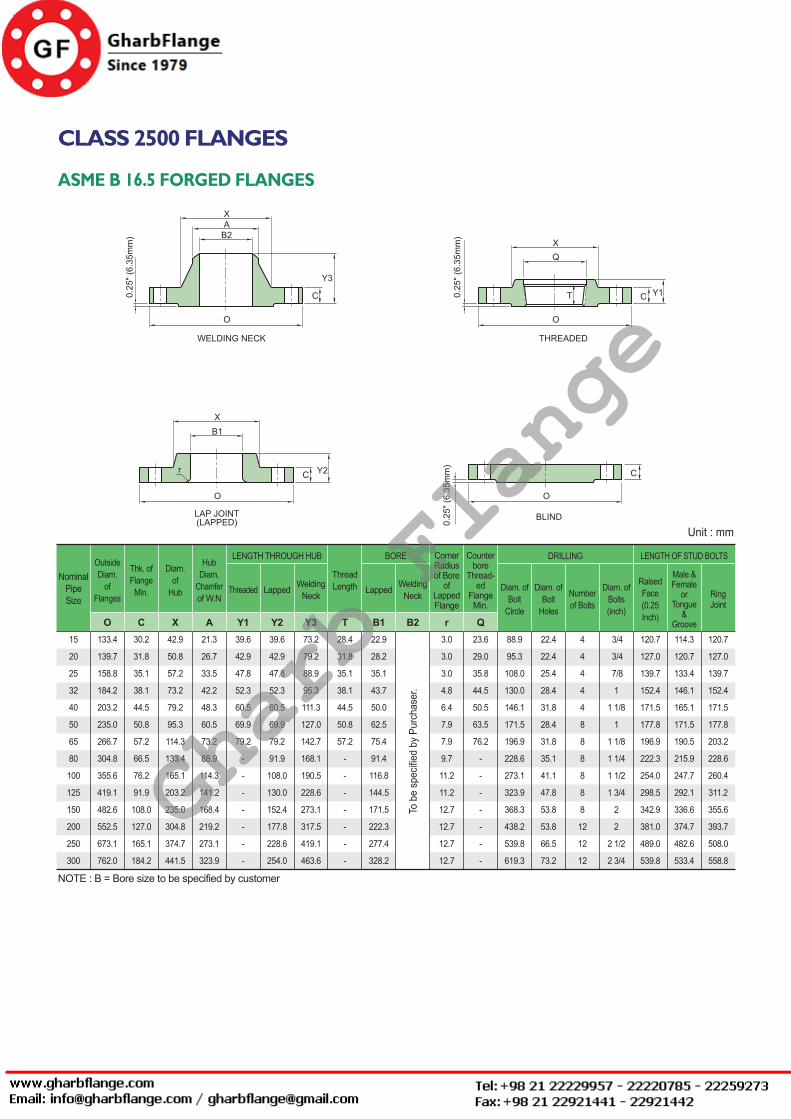
CLASS 150 FLANGES
ASME B 16.5 FORGED FLANGES
NOTE :1. Class 150 flanges except Lap Joint will be furnished with 0.06" (1.6mm) raised face, which is included in ‘Thickness’ (C) and ‘Length through Hub’ (Y1), (Y3).2. For Slip-on, Threaded, Socket Welding and Lap Joint Flanges, the hubs can be shaped either vertical from base to top or tapered within the limits of 7 degrees.
OutsideDiam.
ofFlanges
Thk. ofFlange
Min.
Diam.of
Hub
O.D ofRaisedFace
HubDiam.
Chamferof W.N
ThreadedSlip-onSocketWelding
Lapped WeldingNeck
Slip-onSocketWelding
LappedWelding
NeckSocketWelding
Diam. of BoltCircle
Diam. of BoltHoles
Numberof Bolts
Diam. ofBolts 0.06 in
Raised Face
CornerRadiusof Bore
ofLappedFlange
Depthof
Socket
ThreadLength
LENGTH THROUGH HUB BORE DRILLING LENGTH OF STUD BOLTS
O C X G A Y1 Y2 Y3 T B1 B2 B3 r D
NominalPipeSize
0.44
0.50
0.56
0.62
0.69
0.75
0.88
0.94
0.94
0.94
0.94
1.00
1.12
1.19
1.25
1.38
1.44
1.56
1.69
1.88
1.19
1.50
1.94
2.31
2.56
3.06
3.56
4.25
4.81
5.31
6.44
7.56
9.69
12.00
14.38
15.75
18.00
19.88
22.00
26.12
1.38
1.69
2.00
2.50
2.88
3.62
4.12
5.00
5.50
6.19
7.31
8.50
10.62
12.75
15.00
16.25
18.50
21.00
23.00
27.25
0.84
1.05
1.32
1.66
1.90
2.38
2.88
3.50
4.00
4.50
5.56
6.63
8.63
10.75
12.75
14.00
16.00
18.00
20.00
24.00
0.62
0.62
0.69
0.81
0.88
1.00
1.12
1.19
1.25
1.31
1.44
1.56
1.75
1.94
2.19
2.25
2.50
2.69
2.88
3.25
0.62
0.62
0.69
0.81
0.88
1.00
1.12
1.19
1.25
1.31
1.44
1.56
1.75
1.94
2.19
3.12
3.44
3.81
4.06
4.38
1.88
2.06
2.19
2.25
2.44
2.50
2.75
2.75
2.81
3.00
3.50
3.50
4.00
4.00
4.50
5.00
5.00
5.50
5.69
6.00
0.62
0.62
0.69
0.81
0.88
1.00
1.12
1.19
1.25
1.31
1.44
1.56
1.75
1.94
2.19
2.25
2.50
2.69
2.88
3.25
0.88
1.09
1.36
1.70
1.95
2.44
2.94
3.57
4.07
4.57
5.66
6.72
8.72
10.88
12.88
14.14
16.16
18.18
20.20
24.25
0.90
1.11
1.38
1.72
1.97
2.46
2.97
3.60
4.10
4.60
5.69
6.75
8.75
10.92
12.92
14.18
16.19
18.20
20.25
24.25
To be
specified
by
purchaser
0.62
0.82
1.05
1.38
1.61
2.07
2.47
3.07
3.55
4.03
5.05
6.07
7.98
10.02
12.00
0.12
0.12
0.12
0.19
0.25
0.31
0.31
0.38
0.38
0.44
0.44
0.50
0.50
0.50
0.50
0.50
0.50
0.50
0.50
0.50
0.38
0.44
0.50
0.56
0.62
0.69
0.75
0.81
-
-
-
-
-
-
-
-
-
-
-
-
2.38
2.75
3.12
3.50
3.88
4.75
5.50
6.00
7.00
7.50
8.50
9.50
11.75
14.25
17.00
18.75
21.25
22.75
25.00
29.50
0.62
0.62
0.62
0.62
0.62
0.75
0.75
0.75
0.75
0.75
0.88
0.88
0.88
1.00
1.00
1.12
1.12
1.25
1.25
1.38
4
4
4
4
4
4
4
4
8
8
8
8
8
12
12
12
16
16
20
20
1/2
1/2
1/2
1/2
1/2
5/8
5/8
5/8
5/8
5/8
3/4
3/4
3/4
7/8
7/8
1
1
1 1/8
1 1/8
1 1/4
2.00
2.00
2.25
2.25
2.50
2.75
3.00
3.00
3.00
3.00
3.25
3.25
3.50
4.00
4.00
4.50
4.50
5.00
5.50
6.00
-
-
3.00
3.25
3.25
3.75
4.00
4.00
4.00
4.00
4.25
4.50
4.75
5.00
5.25
5.75
5.75
6.25
6.75
7.25
2.25
2.50
2.50
2.75
2.75
3.25
3.50
3.50
3.50
3.50
3.75
4.00
4.25
4.50
4.75
5.25
5.25
5.75
6.25
6.75
3.50
3.88
4.25
4.62
5.00
6.00
7.00
7.50
8.50
9.00
10.00
11.00
13.50
16.00
19.00
21.00
23.50
25.00
27.50
32.00
1/2
3/4
1
1 1/4
1 1/2
2
2 1/2
3
3 1/2
4
5
6
8
10
12
14
16
18
20
24
Unit : inch
Stud BoltsMachineBolts
0.06 in Raised Face
RingJoint
Gharb Flange
ASME FLANGES
Rev. 3. 0 / 2014. 10. 01 FLANGES - 9
CLASS 150 FLANGES
ASME B 16.5 FORGED FLANGES
3. Blind Flanges may be made with the same hub as that used for Slip-on Flanges or without hub.4. The gasket surface and backside (bearing surface for bolting) are made parallel within 1 degree. To accomplish parallelism, spot facing is carried out according to MSS SP-9, without reducing thickness (C).5. Depth of Socket (D) is covered by ASME B 16.5 only in sizes through 3 inch, over 3 inch is at the manufacturer’s option.
0.06 in Raised Face
OutsideDiam.
ofFlanges
Thk. ofFlange
Min.
Diam.of
Hub
O.D ofRaisedFace
HubDiam.
Chamferof W.N
ThreadedSlip-onSocketWelding
Lapped WeldingNeck
Slip-onSocketWelding
LappedWelding
NeckSocketWelding
Diam. of BoltCircle
Diam. of BoltHoles
Numberof Bolts
Diam. ofBolts(inch)
CornerRadiusof Bore
ofLappedFlange
Depthof
Socket
ThreadLength
LENGTH THROUGH HUB BORE DRILLING LENGTH OF STUD BOLTS
O C X G A Y1 Y2 Y3 T B1 B2 B3 r D
NominalPipeSize
11.2
12.7
14.2
15.7
17.5
19.1
22.4
23.9
23.9
23.9
23.9
25.4
28.4
30.2
31.8
35.1
36.6
39.6
42.9
47.8
30.2
38.1
49.3
58.7
65.0
77.7
90.4
108.0
122.2
134.9
163.6
192.0
246.1
304.8
365.3
400.1
457.2
505.0
558.8
663.4
35.1
42.9
50.8
63.5
73.2
91.9
104.6
127.0
139.7
157.2
185.7
215.9
269.7
323.9
381.0
412.8
469.9
533.4
584.2
692.2
21.3
26.7
33.5
42.2
48.3
60.5
73.2
88.9
101.6
114.3
141.2
168.4
219.2
273.1
323.9
355.6
406.4
457.2
508.0
609.6
15.7
15.7
17.5
20.6
22.4
25.4
28.4
30.2
31.8
33.3
36.6
39.6
44.5
49.3
55.6
57.2
63.5
68.3
73.2
82.6
15.7
15.7
17.5
20.6
22.4
25.4
28.4
30.2
31.8
33.3
36.6
39.6
44.5
49.3
55.6
79.2
87.4
96.8
103.1
111.3
47.8
52.3
55.6
57.2
62.0
63.5
69.9
69.9
71.4
76.2
88.9
88.9
101.6
101.6
114.3
127.0
127.0
139.7
144.5
152.4
15.7
15.7
17.5
20.6
22.4
25.4
28.4
30.2
31.8
33.3
36.6
39.6
44.5
49.3
55.6
57.2
63.5
68.3
73.2
82.6
22.4
27.7
34.5
43.2
49.5
62.0
74.7
90.7
103.4
116.1
143.8
170.7
221.5
276.4
327.2
359.2
410.5
461.8
513.1
616.0
22.9
28.2
35.1
43.7
50.0
62.5
75.4
91.4
104.1
116.8
144.5
171.5
222.3
277.4
328.2
360.2
411.2
462.3
514.4
616.0
15.8
20.8
26.7
35.1
40.9
52.6
62.7
78..0
90.2
102.4
128.3
154.2
202.7
254.5
304.8
-
-
-
-
-
3.0
3.0
3.0
4.8
6.4
7.9
7.9
9.7
9.7
11.2
11.2
12.7
12.7
12.7
12.7
12.7
12.7
12.7
12.7
12.7
9.7
11.2
12.7
14.2
15.8
17.5
19.1
20.6
-
-
-
-
-
-
-
-
-
-
-
-
60.5
69.9
79.3
88.9
98.6
120.7
139.7
152.4
177.8
190.5
215.9
241.3
298.5
362.0
431.8
476.3
539.8
577.9
635.0
749.3
15.8
15.8
15.8
15.8
15.8
19.1
19.1
19.1
19.1
19.1
22.4
22.4
22.4
25.4
25.4
28.5
28.5
31.8
31.8
35.1
4
4
4
4
4
4
4
4
8
8
8
8
8
12
12
12
16
16
20
20
1/2
1/2
1/2
1/2
1/2
5/8
5/8
5/8
5/8
5/8
3/4
3/4
3/4
7/8
7/8
1
1
1 1/8
1 1/8
1 1/4
50.8
50.8
57.2
57.2
63.5
69.9
76.2
76.2
76.2
76.2
82.6
82.6
88.9
101.6
101.6
114.3
114.3
127.0
139.7
152.4
57.2
63.5
63.5
69.9
69.9
82.6
88.9
88.9
88.9
88.9
95.3
101.6
108.0
114.3
120.7
133.4
133.4
146.1
158.8
171.5
-
-
76.2
82.6
82.6
95.3
101.6
101.6
101.6
101.6
108.0
114.3
120.7
127.0
133.4
146.1
146.1
158.8
171.5
184.2
89.0
98.5
108.0
117.5
127.0
152.5
178.0
190.5
216.0
228.5
254.0
279.5
343.0
406.5
482.5
533.5
597.0
635.0
698.5
813.0
15
20
25
32
40
50
65
80
90
100
125
150
200
250
300
350
400
450
500
600
Unit : mm
Stud BoltsMachineBolts
0.06 in Raised Face
RingJoint
Gharb Flange

Rev. 3. 0 / 2014. 10. 01FLANGES - 10
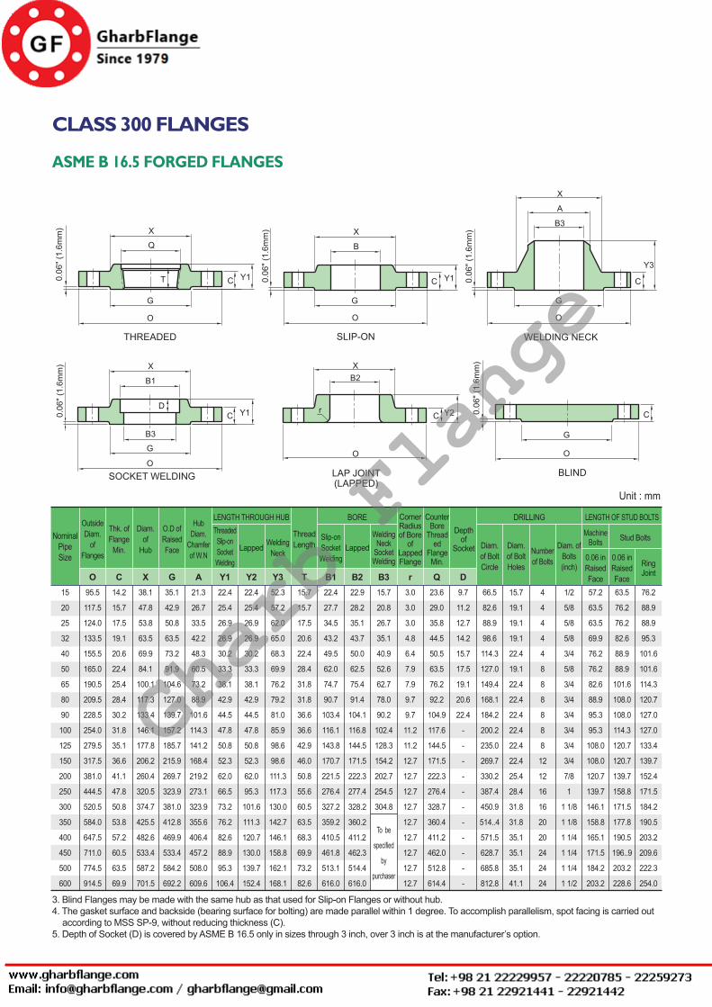
CLASS 300 FLANGES
ASME B 16.5 FORGED FLANGES
NOTE :1. Class 300 flanges except Lap Joint will be furnished with 0.06" (1.6mm) raised face, which is included in ‘Thickness’ (C) and ‘Length through Hub’ (Y1), (Y3).2. For Slip-on, Threaded, Socket Welding and Lap Joint Flanges, the hubs can be shaped either vertical from base to top or tapered within the limits of 7 degrees.
OutsideDiam.
ofFlanges
Thk. ofFlange
Min.
Diam.of
Hub
O.D ofRaisedFace
HubDiam.
Chamferof W.N
ThreadedSlip-onSocketWelding
Lapped WeldingNeck
Slip-onSocketWelding
LappedWelding
NeckSocketWelding
Diam. of BoltCircle
Diam. of BoltHoles
Numberof Bolts
Diam. ofBolts
CornerRadiusof Bore
ofLappedFlange
CounterBore
Threaded
FlangeMin.
Depthof
Socket
ThreadLength
LENGTH THROUGH HUB BORE DRILLING LENGTH OF STUD BOLTS
O C X G A Y1 Y2 Y3 T B1 B2 B3 r Q D
NominalPipeSize
0.56
0.62
0.69
0.75
0.81
0.88
1.00
1.12
1.19
1.25
1.38
1.44
1.62
1.88
2.00
2.12
2.25
2.38
2.50
2.75
1.50
1.88
2.12
2.50
2.75
3.31
3.94
4.62
5.25
5.75
7.00
8.12
10.25
12.62
14.75
16.75
19.00
21.00
23.12
27.62
1.38
1.69
2.00
2.50
2.88
3.62
4.12
5.00
5.50
6.19
7.31
8.50
10.62
12.75
15.00
16.25
18.50
21.00
23.00
27.25
0.84
1.05
1.32
1.66
1.90
2.38
2.88
3.50
4.00
4.50
5.56
6.63
8.63
10.75
12.75
14.00
16.00
18.00
20.00
24.00
0.88
1.00
1.06
1.06
1.19
1.31
1.50
1.69
1.75
1.88
2.00
2.06
2.44
2.62
2.88
3.00
3.25
3.50
3.75
4.19
0.88
1.00
1.06
1.06
1.19
1.31
1.50
1.69
1.75
1.88
2.00
2.06
2.44
3.75
4.00
4.38
4.75
5.12
5.50
6.00
2.06
2.25
2.44
2.56
2.69
2.75
3.00
3.12
3.19
3.38
3.88
3.88
4.38
4.62
5.12
5.62
5.75
6.25
6.38
6.62
0.62
0.62
0.69
0.81
0.88
1.12
1.25
1.25
1.44
1.44
1.69
1.81
2.00
2.19
2.38
2.50
2.69
2.75
2.88
3.25
0.88
1.09
1.36
1.70
1.95
2.44
2.94
3.57
4.07
4.57
5.66
6.72
8.72
10.88
12.88
14.14
16.16
18.18
20.20
24.25
0.90
1.11
1.38
1.72
1.97
2.46
2.97
3.60
4.10
4.60
5.69
6.75
8.75
10.92
12.92
14.18
16.19
18.20
20.25
24.25
0.62
0.82
1.05
1.38
1.61
2.07
2.47
3.07
3.55
4.03
5.05
6.07
7.98
10.02
12.00
0.12
0.12
0.12
0.19
0.25
0.31
0.31
0.38
0.38
0.44
0.44
0.50
0.50
0.50
0.50
0.50
0.50
0.50
0.50
0.50
0.93
1.14
1.41
1.75
1.98
2.50
3.00
3.63
4.13
4.63
5.69
6.75
8.75
10.88
12.94
14.19
16.19
18.19
20.19
24.19
0.38
0.44
0.50
0.56
0.62
0.69
0.75
0.81
-
-
-
-
-
-
-
-
-
-
-
-
2.62
3.25
3.50
3.88
4.50
5.00
5.88
6.62
7.25
7.88
9.25
10.62
13.00
15.25
17.75
20.25
22.50
24.75
27.00
32.00
0.62
0.75
0.75
0.75
0.88
0.75
0.88
0.88
0.88
0.88
0.88
0.88
1.00
1.12
1.25
1.25
1.38
1.38
1.38
1.62
4
4
4
4
4
8
8
8
8
8
8
12
12
16
16
20
20
24
24
24
1/2
5/8
5/8
5/8
3/4
5/8
3/4
3/4
3/4
3/4
3/4
3/4
7/8
1
1 1/8
1 1/8
1 1/4
1 1/4
1 1/4
1 1/2
2.50
3.00
3.00
3.25
3.50
3.50
4.00
4.25
4.25
4.50
4.75
4.75
5.50
6.25
6.75
7.00
7.50
7.75
8.00
9.00
3.00
3.50
3.50
3.75
4.00
4.00
4.50
4.75
5.00
5.00
5.25
5.50
6.00
6.75
7.25
7.50
8.00
8.25
8.75
10.00
2.25
2.50
2.50
2.75
3.00
3.00
3.25
3.50
3.75
3.75
4.25
4.25
4.75
5.50
5.75
6.25
6.50
6.75
7.25
8.00
To be
specified
by
purchaser
3.75
4.62
4.88
5.25
6.12
6.50
7.50
8.25
9.00
10.00
11.00
12.50
15.00
17.50
20.50
23.00
25.50
28.00
30.50
36.00
1/2
3/4
1
1 1/4
1 1/2
2
2 1/2
3
3 1/2
4
5
6
8
10
12
14
16
18
20
24
Unit : inch
0.06 in Raised Face
Stud BoltsMachineBolts
0.06 in Raised Face
RingJoint
Gharb Flange
ASME FLANGES
Rev. 3. 0 / 2014. 10. 01 FLANGES - 11
CLASS 300 FLANGES
ASME B 16.5 FORGED FLANGES
3. Blind Flanges may be made with the same hub as that used for Slip-on Flanges or without hub.4. The gasket surface and backside (bearing surface for bolting) are made parallel within 1 degree. To accomplish parallelism, spot facing is carried out according to MSS SP-9, without reducing thickness (C).5. Depth of Socket (D) is covered by ASME B 16.5 only in sizes through 3 inch, over 3 inch is at the manufacturer’s option.
Unit : mm
OutsideDiam.
ofFlanges
Thk. ofFlange
Min.
Diam.of
Hub
O.D ofRaisedFace
HubDiam.
Chamferof W.N
ThreadedSlip-onSocketWelding
Lapped WeldingNeck
Slip-onSocketWelding
LappedWelding
NeckSocketWelding
Diam. of BoltCircle
Diam. of BoltHoles
Numberof Bolts
Diam. ofBolts(inch)
CornerRadiusof Bore
ofLappedFlange
CounterBore
Threaded
FlangeMin.
Depthof
Socket
ThreadLength
LENGTH THROUGH HUB BORE DRILLING LENGTH OF STUD BOLTS
O C X G A Y1 Y2 Y3 T B1 B2 B3 r Q D
NominalPipeSize
14.2
15.7
17.5
19.1
20.6
22.4
25.4
28.4
30.2
31.8
35.1
36.6
41.1
47.8
50.8
53.8
57.2
60.5
63.5
69.9
38.1
47.8
53.8
63.5
69.9
84.1
100.1
117.3
133.4
146.1
177.8
206.2
260.4
320.5
374.7
425.5
482.6
533.4
587.2
701.5
35.1
42.9
50.8
63.5
73.2
91.9
104.6
127.0
139.7
157.2
185.7
215.9
269.7
323.9
381.0
412.8
469.9
533.4
584.2
692.2
21.3
26.7
33.5
42.2
48.3
60.5
73.2
88.9
101.6
114.3
141.2
168.4
219.2
273.1
323.9
355.6
406.4
457.2
508.0
609.6
22.4
25.4
26.9
26.9
30.2
33.3
38.1
42.9
44.5
47.8
50.8
52.3
62.0
66.5
73.2
76.2
82.6
88.9
95.3
106.4
22.4
25.4
26.9
26.9
30.2
33.3
38.1
42.9
44.5
47.8
50.8
52.3
62.0
95.3
101.6
111.3
120.7
130.0
139.7
152.4
52.3
57.2
62.0
65.0
68.3
69.9
76.2
79.2
81.0
85.9
98.6
98.6
111.3
117.3
130.0
142.7
146.1
158.8
162.1
168.1
15.7
15.7
17.5
20.6
22.4
28.4
31.8
31.8
36.6
36.6
42.9
46.0
50.8
55.6
60.5
63.5
68.3
69.9
73.2
82.6
22.4
27.7
34.5
43.2
49.5
62.0
74.7
90.7
103.4
116.1
143.8
170.7
221.5
276.4
327.2
359.2
410.5
461.8
513.1
616.0
22.9
28.2
35.1
43.7
50.0
62.5
75.4
91.4
104.1
116.8
144.5
171.5
222.3
277.4
328.2
360.2
411.2
462.3
514.4
616.0
15.7
20.8
26.7
35.1
40.9
52.6
62.7
78.0
90.2
102.4
128.3
154.2
202.7
254.5
304.8
3.0
3.0
3.0
4.8
6.4
7.9
7.9
9.7
9.7
11.2
11.2
12.7
12.7
12.7
12.7
12.7
12.7
12.7
12.7
12.7
23.6
29.0
35.8
44.5
50.5
63.5
76.2
92.2
104.9
117.6
144.5
171.5
222.3
276.4
328.7
360.4
411.2
462.0
512.8
614.4
9.7
11.2
12.7
14.2
15.7
17.5
19.1
20.6
22.4
-
-
-
-
-
-
-
-
-
-
-
66.5
82.6
88.9
98.6
114.3
127.0
149.4
168.1
184.2
200.2
235.0
269.7
330.2
387.4
450.9
514..4
571.5
628.7
685.8
812.8
15.7
19.1
19.1
19.1
22.4
19.1
22.4
22.4
22.4
22.4
22.4
22.4
25.4
28.4
31.8
31.8
35.1
35.1
35.1
41.1
4
4
4
4
4
8
8
8
8
8
8
12
12
16
16
20
20
24
24
24
1/2
5/8
5/8
5/8
3/4
5/8
3/4
3/4
3/4
3/4
3/4
3/4
7/8
1
1 1/8
1 1/8
1 1/4
1 1/4
1 1/4
1 1/2
57.2
63.5
63.5
69.9
76.2
76.2
82.6
88.9
95.3
95.3
108.0
108.0
120.7
139.7
146.1
158.8
165.1
171.5
184.2
203.2
63.5
76.2
76.2
82.6
88.9
88.9
101.6
108.0
108.0
114.3
120.7
120.7
139.7
158.8
171.5
177.8
190.5
196..9
203.2
228.6
76.2
88.9
88.9
95.3
101.6
101.6
114.3
120.7
127.0
127.0
133.4
139.7
152.4
171.5
184.2
190.5
203.2
209.6
222.3
254.0
95.5
117.5
124.0
133.5
155.5
165.0
190.5
209.5
228.5
254.0
279.5
317.5
381.0
444.5
520.5
584.0
647.5
711.0
774.5
914.5
15
20
25
32
40
50
65
80
90
100
125
150
200
250
300
350
400
450
500
600
0.06 in Raised Face
Stud BoltsMachineBolts
0.06 in Raised Face
RingJoint
To be
specified
by
purchaser
Gharb Flange
Rev. 3. 0 / 2014. 10. 01FLANGES - 12
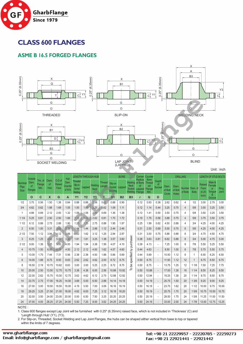
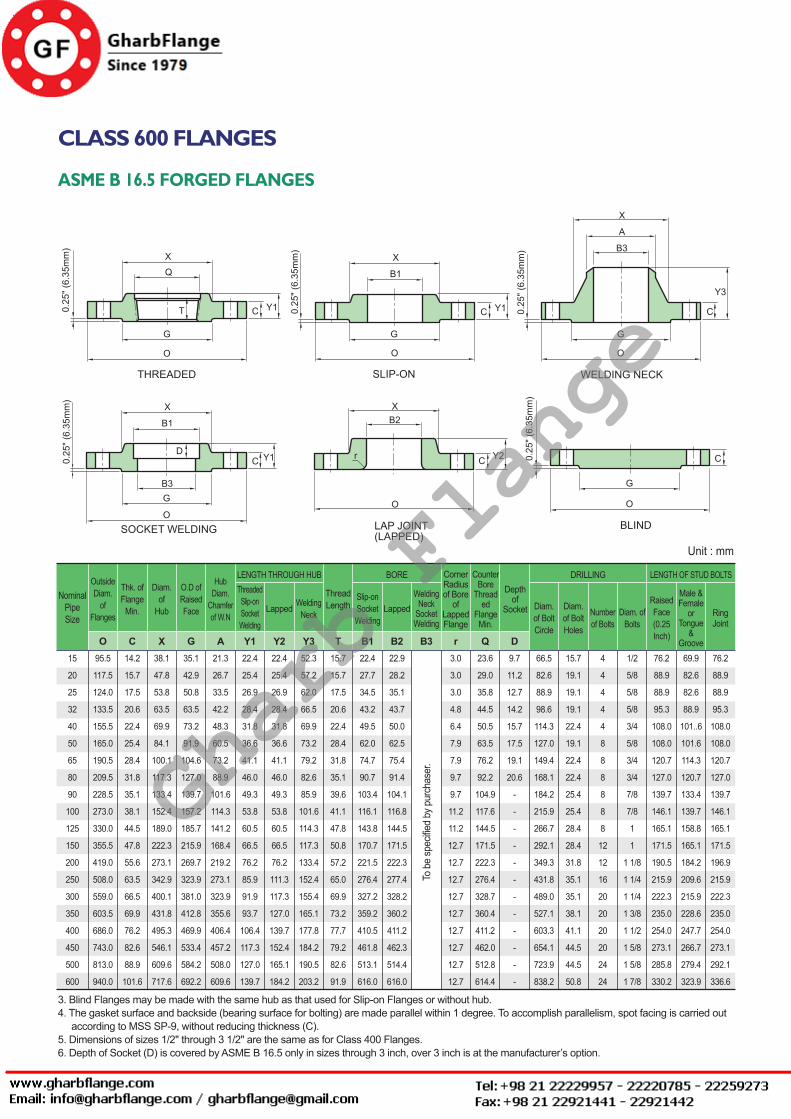
CLASS 600 FLANGES
ASME B 16.5 FORGED FLANGES
NOTE :1. Class 600 flanges except Lap Joint will be furnished with 0.25" (6.35mm) raised face, which is not included in ‘Thickness’ (C) and ‘Length through Hub’ (Y1), (Y3).2. For Slip-on, Threaded, Socket Welding and Lap Joint Flanges, the hubs can be shaped either vertical from base to top or tapered within the limits of 7 degrees.
OutsideDiam.
ofFlanges
Thk. ofFlange
Min.
Diam.of
Hub
O.D ofRaisedFace
HubDiam.
Chamferof W.N
ThreadedSlip-onSocketWelding
Lapped WeldingNeck
Slip-onSocketWelding
LappedWelding
NeckSocketWelding
Diam. of BoltCircle
Diam. of BoltHoles
Numberof Bolts
Diam. ofBolts
RaisedFace(0.25Inch)
Male &Female
orTongue
&Groove
RingJoint
CornerRadiusof Bore
ofLappedFlange
CounterBore
Threaded
FlangeMin.
Depthof
Socket
ThreadLength
LENGTH THROUGH HUB BORE DRILLING LENGTH OF STUD BOLTS
O C X G A Y1 Y2 Y3 T B1 B2 B3 r Q D
NominalPipeSize
0.56
0.62
0.69
0.81
0.88
1.00
1.12
1.25
1.38
1.50
1.75
1.88
2.19
2.50
2.62
2.75
3.00
3.25
3.50
4.00
1.50
1.88
2.12
2.50
2.75
3.31
3.94
4.62
5.25
6.00
7.44
8.75
10.75
13.50
15.75
17.00
19.50
21.50
24.00
28.25
1.38
1.69
2.00
2.50
2.88
3.62
4.12
5.00
5.50
6.19
7.31
8.50
10.62
12.75
15.00
16.25
18.50
21.00
23.00
27.25
0.84
1.05
1.32
1.66
1.90
2.38
2.88
3.50
4.00
4.50
5.56
6.63
8.63
10.75
12.75
14.00
16.00
18.00
20.00
24.00
0.88
1.00
1.06
1.12
1.25
1.44
1.62
1.81
1.94
2.12
2.38
2.62
3.00
3.38
3.62
3.69
4.19
4.62
5.00
5.50
0.88
1.00
1.06
1.12
1.25
1.44
1.62
1.81
1.94
2.12
2.38
2.62
3.00
4.38
4.62
5.00
5.50
6.00
6.50
7.25
2.06
2.25
2.44
2.62
2.75
2.88
3.12
3.25
3.38
4.00
4.50
4.62
5.25
6.00
6.12
6.50
7.00
7.25
7.50
8.00
0.62
0.62
0.69
0.81
0.88
1.12
1.25
1.38
1.56
1.62
1.88
2.00
2.25
2.56
2.75
2.88
3.06
3.12
3.25
3.62
0.88
1.09
1.36
1.70
1.95
2.44
2.94
3.57
4.07
4.57
5.66
6.72
8.72
10.88
12.88
14.14
16.16
18.18
20.20
24.25
0.90
1.11
1.38
1.72
1.97
2.46
2.97
3.60
4.10
4.60
5.69
6.75
8.75
10.92
12.92
14.18
16.19
18.20
20.25
24.25
0.12
0.12
0.12
0.19
0.25
0.31
0.31
0.38
0.38
0.44
0.44
0.50
0.50
0.50
0.50
0.50
0.50
0.50
0.50
0.50
0.93
1.14
1.41
1.75
1.99
2.50
3.00
3.63
4.13
4.63
5.69
6.75
8.75
10.88
12.94
14.19
16.19
18.19
20.19
24.19
0.38
0.44
0.50
0.56
0.62
0.69
0.75
0.81
-
-
-
-
-
-
-
-
-
-
-
-
2.62
3.25
3.50
3.88
4.50
5.00
5.88
6.62
7.25
8.50
10.50
11.50
13.75
17.00
19.25
20.75
23.75
25.75
28.50
33.00
0.62
0.75
0.75
0.75
0.88
0.75
0.88
0.88
1.00
1.00
1.12
1.12
1.25
1.38
1.38
1.50
1.62
1.75
1.75
2.00
4
4
4
4
4
8
8
8
8
8
8
12
12
16
20
20
20
20
24
24
1/2
5/8
5/8
5/8
3/4
5/8
3/4
3/4
7/8
7/8
1
1
1 1/8
1 1/4
1 1/4
1 3/8
1 1/2
1 5/8
1 5/8
1 7/8
3.00
3.50
3.50
3.75
4.25
4.25
4.75
5.00
5.50
5.75
6.50
6.75
7.50
8.50
8.75
9.25
10.00
10.75
11.25
13.00
2.75
3.25
3.25
3.50
4.00
4.00
4.50
4.75
5.25
5.50
6.25
6.50
7.25
8.25
8.50
9.00
9.75
10.50
11.00
12.75
3.00
3.50
3.50
3.75
4.25
4.25
4.75
5.00
5.50
5.75
6.50
6.75
7.75
8.50
8.75
9.25
10.00
10.75
11.50
13.25
3.75
4.62
4.88
5.25
6.12
6.50
7.50
8.25
9.00
10.75
13.00
14.00
16.50
20.00
22.00
23.75
27.00
29.25
32.00
37.00
1/2
3/4
1
1 1/4
1 1/2
2
2 1/2
3
3 1/2
4
5
6
8
10
12
14
16
18
20
24
Unit : inch
To b
e sp
ecifie
d by
pur
chas
er.
Gharb Flange
ASME FLANGES
Rev. 3. 0 / 2014. 10. 01 FLANGES - 13
CLASS 600 FLANGES
ASME B 16.5 FORGED FLANGES
3. Blind Flanges may be made with the same hub as that used for Slip-on Flanges or without hub.4. The gasket surface and backside (bearing surface for bolting) are made parallel within 1 degree. To accomplish parallelism, spot facing is carried out according to MSS SP-9, without reducing thickness (C).5. Dimensions of sizes 1/2" through 3 1/2" are the same as for Class 400 Flanges.6. Depth of Socket (D) is covered by ASME B 16.5 only in sizes through 3 inch, over 3 inch is at the manufacturer’s option.
Unit : mm
OutsideDiam.
ofFlanges
Thk. ofFlange
Min.
Diam.of
Hub
O.D ofRaisedFace
HubDiam.
Chamferof W.N
ThreadedSlip-onSocketWelding
Lapped WeldingNeck
Slip-onSocketWelding
LappedWelding
NeckSocketWelding
Diam. of BoltCircle
Diam. of BoltHoles
Numberof Bolts
Diam. ofBolts
RaisedFace(0.25Inch)
Male &Female
orTongue
&Groove
RingJoint
CornerRadiusof Bore
ofLappedFlange
CounterBore
Threaded
FlangeMin.
Depthof
Socket
ThreadLength
LENGTH THROUGH HUB BORE DRILLING LENGTH OF STUD BOLTS
O C X G A Y1 Y2 Y3 T B1 B2 B3 r Q D
NominalPipeSize
14.2
15.7
17.5
20.6
22.4
25.4
28.4
31.8
35.1
38.1
44.5
47.8
55.6
63.5
66.5
69.9
76.2
82.6
88.9
101.6
38.1
47.8
53.8
63.5
69.9
84.1
100.1
117.3
133.4
152.4
189.0
222.3
273.1
342.9
400.1
431.8
495.3
546.1
609.6
717.6
35.1
42.9
50.8
63.5
73.2
91.9
104.6
127.0
139.7
157.2
185.7
215.9
269.7
323.9
381.0
412.8
469.9
533.4
584.2
692.2
21.3
26.7
33.5
42.2
48.3
60.5
73.2
88.9
101.6
114.3
141.2
168.4
219.2
273.1
323.9
355.6
406.4
457.2
508.0
609.6
22.4
25.4
26.9
28.4
31.8
36.6
41.1
46.0
49.3
53.8
60.5
66.5
76.2
85.9
91.9
93.7
106.4
117.3
127.0
139.7
22.4
25.4
26.9
28.4
31.8
36.6
41.1
46.0
49.3
53.8
60.5
66.5
76.2
111.3
117.3
127.0
139.7
152.4
165.1
184.2
52.3
57.2
62.0
66.5
69.9
73.2
79.2
82.6
85.9
101.6
114.3
117.3
133.4
152.4
155.4
165.1
177.8
184.2
190.5
203.2
15.7
15.7
17.5
20.6
22.4
28.4
31.8
35.1
39.6
41.1
47.8
50.8
57.2
65.0
69.9
73.2
77.7
79.2
82.6
91.9
22.4
27.7
34.5
43.2
49.5
62.0
74.7
90.7
103.4
116.1
143.8
170.7
221.5
276.4
327.2
359.2
410.5
461.8
513.1
616.0
22.9
28.2
35.1
43.7
50.0
62.5
75.4
91.4
104.1
116.8
144.5
171.5
222.3
277.4
328.2
360.2
411.2
462.3
514.4
616.0
3.0
3.0
3.0
4.8
6.4
7.9
7.9
9.7
9.7
11.2
11.2
12.7
12.7
12.7
12.7
12.7
12.7
12.7
12.7
12.7
23.6
29.0
35.8
44.5
50.5
63.5
76.2
92.2
104.9
117.6
144.5
171.5
222.3
276.4
328.7
360.4
411.2
462.0
512.8
614.4
9.7
11.2
12.7
14.2
15.7
17.5
19.1
20.6
-
-
-
-
-
-
-
-
-
-
-
-
66.5
82.6
88.9
98.6
114.3
127.0
149.4
168.1
184.2
215.9
266.7
292.1
349.3
431.8
489.0
527.1
603.3
654.1
723.9
838.2
15.7
19.1
19.1
19.1
22.4
19.1
22.4
22.4
25.4
25.4
28.4
28.4
31.8
35.1
35.1
38.1
41.1
44.5
44.5
50.8
4
4
4
4
4
8
8
8
8
8
8
12
12
16
20
20
20
20
24
24
1/2
5/8
5/8
5/8
3/4
5/8
3/4
3/4
7/8
7/8
1
1
1 1/8
1 1/4
1 1/4
1 3/8
1 1/2
1 5/8
1 5/8
1 7/8
76.2
88.9
88.9
95.3
108.0
108.0
120.7
127.0
139.7
146.1
165.1
171.5
190.5
215.9
222.3
235.0
254.0
273.1
285.8
330.2
69.9
82.6
82.6
88.9
101..6
101.6
114.3
120.7
133.4
139.7
158.8
165.1
184.2
209.6
215.9
228.6
247.7
266.7
279.4
323.9
76.2
88.9
88.9
95.3
108.0
108.0
120.7
127.0
139.7
146.1
165.1
171.5
196.9
215.9
222.3
235.0
254.0
273.1
292.1
336.6
95.5
117.5
124.0
133.5
155.5
165.0
190.5
209.5
228.5
273.0
330.0
355.5
419.0
508.0
559.0
603.5
686.0
743.0
813.0
940.0
15
20
25
32
40
50
65
80
90
100
125
150
200
250
300
350
400
450
500
600
To b
e sp
ecifie
d by
pur
chas
er.
Gharb Flange
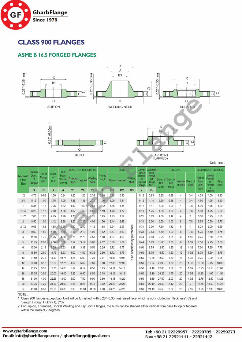
Rev. 3. 0 / 2014. 10. 01FLANGES - 14
CLASS 900 FLANGES
ASME B 16.5 FORGED FLANGES
OutsideDiam.
ofFlanges
Thk. ofFlange
Min.
Diam.of
Hub
HubDiam.
Chamferof W.N
ThreadedSlip-on Lapped Welding
Neck Slip-on Lapped WeldingNeck
Diam. ofBolt
Circle
Diam. ofBolt
Holes
Numberof Bolts
Diam. ofBolts
RaisedFace(0.25Inch)
Male &Female
orTongue
&Groove
RingJoint
CornerRadiusof Bore
ofLappedFlange
Counterbore
Thread-ed
FlangeMin.
ThreadLength
LENGTH THROUGH HUB BORE DRILLING LENGTH OF STUD BOLTS
O C X A Y1 Y2 Y3 T B1 B2 B3 r Q
NominalPipeSize
4.25
4.50
5.00
5.00
5.50
5.75
6.25
5.75
6.75
7.50
7.75
8.75
9.25
10.00
11.00
11.50
13.25
14.25
18.00
4.00
4.25
4.75
4.75
5.25
5.50
6.00
5.50
6.50
7.25
7.25
8.50
9.00
9.75
10.50
11.00
12.50
13.50
17.00
4.25
4.50
5.00
5.00
5.50
5.75
6.25
5.75
6.75
7.50
7.50
8.75
9.25
10.00
10.75
11.25
12.75
13.75
17.25
3/4
3/4
7/8
7/8
1
7/8
1
7/8
1 1/8
1 1/4
1 1/8
1 3/8
1 3/8
1 3/8
1 1/2
1 5/8
1 7/8
2
2 1/2
4
4
4
4
4
8
8
8
8
8
12
12
16
20
20
20
20
20
20
0.88
0.88
1.00
1.00
1.12
1.00
1.12
1.00
1.25
1.38
1.25
1.50
1.50
1.50
1.62
1.75
2.00
2.12
2.62
3.25
3.50
4.00
4.38
4.88
6.50
7.50
7.50
9.25
11.00
12.50
15.50
18.50
21.00
22.00
24.25
27.00
29.50
35.50
0.93
1.14
1.41
1.75
1.99
2.50
3.00
3.63
4.63
5.69
6.75
8.75
10.88
12.94
14.19
16.19
18.19
20.19
24.19
0.12
0.12
0.12
0.19
0.25
0.31
0.31
0.38
0.44
0.44
0.50
0.50
0.50
0.50
0.50
0.50
0.50
0.50
0.50
0.90
1.11
1.38
1.72
1.97
2.46
2.97
3.60
4.60
5.69
6.75
8.75
10.92
12.92
14.18
16.19
18.20
20.25
24.25
0.88
1.09
1.36
1.70
1.95
2.44
2.94
3.57
4.57
5.66
6.72
8.72
10.88
12.88
14.14
16.16
18.18
20.20
24.25
0.88
1.00
1.12
1.19
1.25
1.50
1.88
1.62
1.88
2.12
2.25
2.50
2.81
3.00
3.25
3.38
3.50
3.62
4.00
2.38
2.75
2.88
2.88
3.25
4.00
4.12
4.00
4.50
5.00
5.50
6.38
7.25
7.88
8.38
8.50
9.00
9.75
11.50
1.25
1.38
1.62
1.62
1.75
2.25
2.50
2.12
2.75
3.12
3.38
4.50
5.00
5.62
6.12
6.50
7.50
8.25
10.50
1.25
1.38
1.62
1.62
1.75
2.25
2.50
2.12
2.75
3.12
3.38
4.00
4.25
4.62
5.12
5.25
6.00
6.25
8.00
0.84
1.05
1.32
1.66
1.90
2.38
2.88
3.50
4.50
5.56
6.63
8.63
10.75
12.75
14.00
16.00
18.00
20.00
24.00
1.50
1.75
2.06
2.50
2.75
4.12
4.88
5.00
6.25
7.50
9.25
11.75
14.50
16.50
17.75
20.00
22.25
24.50
29.50
0.88
1.00
1.12
1.12
1.25
1.50
1.62
1.50
1.75
2.00
2.19
2.50
2.75
3.12
3.38
3.50
4.00
4.25
5.50
4.75
5.12
5.88
6.25
7.00
8.50
9.62
9.50
11.50
13.75
15.00
18.50
21.50
24.00
25.25
27.75
31.00
33.75
41.00
1/2
3/4
1
1 1/4
1 1/2
2
2 1/2
3
4
5
6
8
10
12
14
16
18
20
24
Unit : inch
To b
e sp
ecifie
d by
pur
chas
er.
NOTE :1. Class 900 flanges except Lap Joint will be furnished with 0.25" (6.35mm) raised face, which is not included in ‘Thickness’ (C) and ‘Length through Hub’ (Y1), (Y3).2. For Slip-on, Threaded, Socket Welding and Lap Joint Flanges, the hubs can be shaped either vertical from base to top or tapered within the limits of 7 degrees.
Gharb Flange
ASME FLANGES
Rev. 3. 0 / 2014. 10. 01 FLANGES - 15
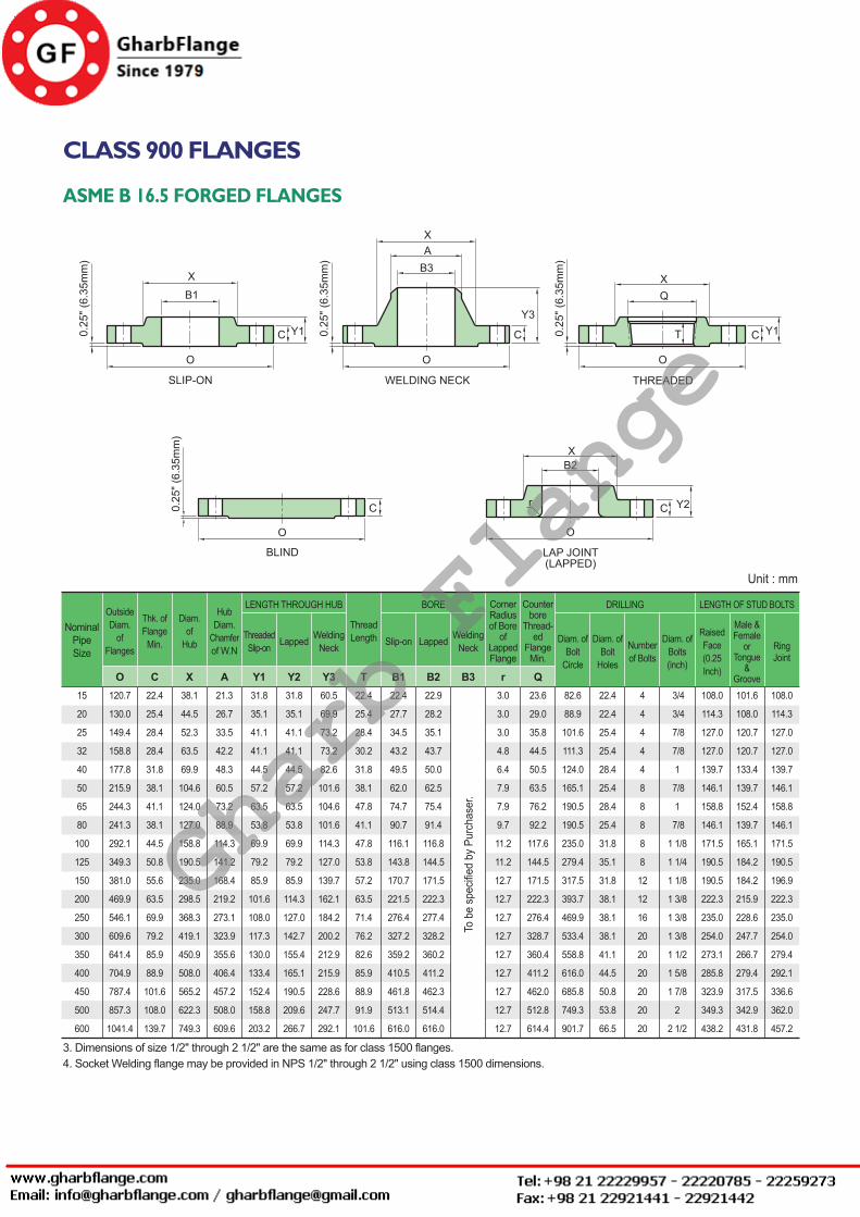
CLASS 900 FLANGES
ASME B 16.5 FORGED FLANGES
OutsideDiam.
ofFlanges
Thk. ofFlange
Min.
Diam.of
Hub
HubDiam.
Chamferof W.N
ThreadedSlip-on Lapped Welding
Neck Slip-on Lapped WeldingNeck
Diam. ofBolt
Circle
Diam. ofBolt
Holes
Numberof Bolts
Diam. ofBolts(inch)
RaisedFace(0.25Inch)
Male &Female
orTongue
&Groove
RingJoint
CornerRadiusof Bore
ofLappedFlange
Counterbore
Thread-ed
FlangeMin.
ThreadLength
LENGTH THROUGH HUB BORE DRILLING LENGTH OF STUD BOLTS
O C X A Y1 Y2 Y3 T B1 B2 B3 r Q
NominalPipeSize
108.0
114.3
127.0
127.0
139.7
146.1
158.8
146.1
171.5
190.5
196.9
222.3
235.0
254.0
279.4
292.1
336.6
362.0
457.2
101.6
108.0
120.7
120.7
133.4
139.7
152.4
139.7
165.1
184.2
184.2
215.9
228.6
247.7
266.7
279.4
317.5
342.9
431.8
108.0
114.3
127.0
127.0
139.7
146.1
158.8
146.1
171.5
190.5
190.5
222.3
235.0
254.0
273.1
285.8
323.9
349.3
438.2
3/4
3/4
7/8
7/8
1
7/8
1
7/8
1 1/8
1 1/4
1 1/8
1 3/8
1 3/8
1 3/8
1 1/2
1 5/8
1 7/8
2
2 1/2
4
4
4
4
4
8
8
8
8
8
12
12
16
20
20
20
20
20
20
22.4
22.4
25.4
25.4
28.4
25.4
28.4
25.4
31.8
35.1
31.8
38.1
38.1
38.1
41.1
44.5
50.8
53.8
66.5
82.6
88.9
101.6
111.3
124.0
165.1
190.5
190.5
235.0
279.4
317.5
393.7
469.9
533.4
558.8
616.0
685.8
749.3
901.7
23.6
29.0
35.8
44.5
50.5
63.5
76.2
92.2
117.6
144.5
171.5
222.3
276.4
328.7
360.4
411.2
462.0
512.8
614.4
3.0
3.0
3.0
4.8
6.4
7.9
7.9
9.7
11.2
11.2
12.7
12.7
12.7
12.7
12.7
12.7
12.7
12.7
12.7
22.9
28.2
35.1
43.7
50.0
62.5
75.4
91.4
116.8
144.5
171.5
222.3
277.4
328.2
360.2
411.2
462.3
514.4
616.0
22.4
27.7
34.5
43.2
49.5
62.0
74.7
90.7
116.1
143.8
170.7
221.5
276.4
327.2
359.2
410.5
461.8
513.1
616.0
22.4
25.4
28.4
30.2
31.8
38.1
47.8
41.1
47.8
53.8
57.2
63.5
71.4
76.2
82.6
85.9
88.9
91.9
101.6
60.5
69.9
73.2
73.2
82.6
101.6
104.6
101.6
114.3
127.0
139.7
162.1
184.2
200.2
212.9
215.9
228.6
247.7
292.1
31.8
35.1
41.1
41.1
44.5
57.2
63.5
53.8
69.9
79.2
85.9
114.3
127.0
142.7
155.4
165.1
190.5
209.6
266.7
31.8
35.1
41.1
41.1
44.5
57.2
63.5
53.8
69.9
79.2
85.9
101.6
108.0
117.3
130.0
133.4
152.4
158.8
203.2
21.3
26.7
33.5
42.2
48.3
60.5
73.2
88.9
114.3
141.2
168.4
219.2
273.1
323.9
355.6
406.4
457.2
508.0
609.6
38.1
44.5
52.3
63.5
69.9
104.6
124.0
127.0
158.8
190.5
235.0
298.5
368.3
419.1
450.9
508.0
565.2
622.3
749.3
22.4
25.4
28.4
28.4
31.8
38.1
41.1
38.1
44.5
50.8
55.6
63.5
69.9
79.2
85.9
88.9
101.6
108.0
139.7
120.7
130.0
149.4
158.8
177.8
215.9
244.3
241.3
292.1
349.3
381.0
469.9
546.1
609.6
641.4
704.9
787.4
857.3
1041.4
15
20
25
32
40
50
65
80
100
125
150
200
250
300
350
400
450
500
600
Unit : mm
To b
e sp
ecifie
d by
Pur
chas
er.
3. Dimensions of size 1/2" through 2 1/2" are the same as for class 1500 flanges.4. Socket Welding flange may be provided in NPS 1/2" through 2 1/2" using class 1500 dimensions.
Gharb Flange
Rev. 3. 0 / 2014. 10. 01FLANGES - 16
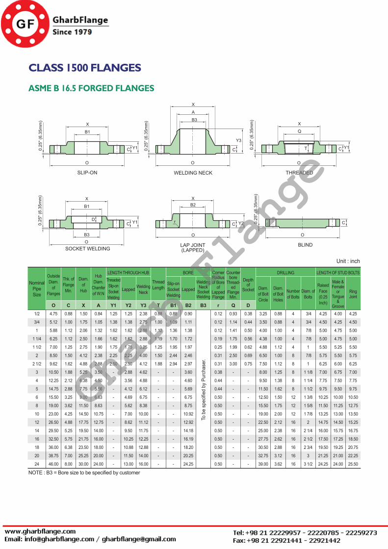
CLASS 1500 FLANGES
ASME B 16.5 FORGED FLANGES
OutsideDiam.
ofFlanges
Thk. ofFlange
Min.
Diam.of
Hub
HubDiam.
Chamferof W.N
ThreadedSlip-onSocketWelding
Lapped WeldingNeck
Slip-onSocketWelding
LappedWelding
NeckSocketWelding
Diam. of BoltCircle
Diam. of BoltHoles
Numberof Bolts
Diam. ofBolts
RaisedFace(0.25Inch)
Male &Female
orTongue
&Groove
RingJoint
CornerRadiusof Bore
ofLappedFlange
Counterbore
Thread-ed
FlangeMin.
Depthof
Socket
ThreadLength
LENGTH THROUGH HUB BORE DRILLING LENGTH OF STUD BOLTS
O C X A Y1 Y2 Y3 T B1 B2 B3 r Q D
NominalPipeSize
4.25
4.50
5.00
5.00
5.50
5.75
6.25
7.00
7.75
9.75
10.50
12.75
13.50
15.25
16.75
18.50
20.75
22.25
25.50
4.00
4.25
4.75
4.75
5.25
5.50
6.00
6.75
7.50
9.50
10.00
11.25
13.00
14.50
15.75
17.25
19.25
21.00
24.00
4.25
4.50
5.00
5.00
5.50
5.75
6.25
7.00
7.75
9.75
10.25
11.50
13.25
14.75
16.00
17.50
19.50
21.25
24.25
3/4
3/4
7/8
7/8
1
7/8
1
1 1/8
1 1/4
1 1/2
1 3/8
1 5/8
1 7/8
2
2 1/4
2 1/2
2 3/4
3
3 1/2
4
4
4
4
4
8
8
8
8
8
12
12
12
16
16
16
16
16
16
0.88
0.88
1.00
1.00
1.12
1.00
1.12
1.25
1.38
1.62
1.50
1.75
2.00
2.12
2.38
2.62
2.88
3.12
3.62
3.25
3.50
4.00
4.38
4.88
6.50
7.50
8.00
9.50
11.50
12.50
15.50
19.00
22.50
25.00
27.75
30.50
32.75
39.00
0.38
0.44
0.50
0.56
0.62
0.69
0.75
-
-
-
-
-
-
-
-
-
-
-
-
0.93
1.14
1.41
1.75
1.99
2.50
3.00
-
-
-
-
-
-
-
-
-
-
-
-
0.12
0.12
0.12
0.19
0.25
0.31
0.31
0.38
0.44
0.44
0.50
0.50
0.50
0.50
0.50
0.50
0.50
0.50
0.50
0.90
1.11
1.38
1.72
1.97
2.46
2.97
3.60
4.60
5.69
6.75
8.75
10.92
12.92
14.18
16.19
18.20
20.25
24.25
0.88
1.09
1.36
1.70
1.95
2.44
2.94
-
-
-
-
-
-
-
-
-
-
-
-
0.88
1.00
1.12
1.19
1.25
1.50
1.88
-
-
-
-
-
-
-
-
-
-
-
-
2.38
2.75
2.88
2.88
3.25
4.00
4.12
4.62
4.88
6.12
6.75
8.38
10.00
11.12
11.75
12.25
12.88
14.00
16.00
1.25
1.38
1.62
1.62
1.75
2.25
2.50
2.88
3.56
4.12
4.69
5.62
7.00
8.62
9.50
10.25
10.88
11.50
13.00
1.25
1.38
1.62
1.62
1.75
2.25
2.50
-
-
-
-
-
-
-
-
-
-
-
-
0.84
1.05
1.32
1.66
1.90
2.38
2.88
3.50
4.50
5.56
6.63
8.63
10.75
12.75
14.00
16.00
18.00
20.00
24.00
1.50
1.75
2.06
2.50
2.75
4.12
4.88
5.25
6.38
7.75
9.00
11.50
14.50
17.75
19.50
21.75
23.50
25.25
30.00
0.88
1.00
1.12
1.12
1.25
1.50
1.62
1.88
2.12
2.88
3.25
3.62
4.25
4.88
5.25
5.75
6.38
7.00
8.00
4.75
5.12
5.88
6.25
7.00
8.50
9.62
10.50
12.25
14.75
15.50
19.00
23.00
26.50
29.50
32.50
36.00
38.75
46.00
1/2
3/4
1
1 1/4
1 1/2
2
2 1/2
3
4
5
6
8
10
12
14
16
18
20
24
Unit : inch
To b
e sp
ecifie
d by
Pur
chas
er.
NOTE : B3 = Bore size to be specified by customer
Gharb Flange
ASME FLANGES
Rev. 3. 0 / 2014. 10. 01 FLANGES - 17
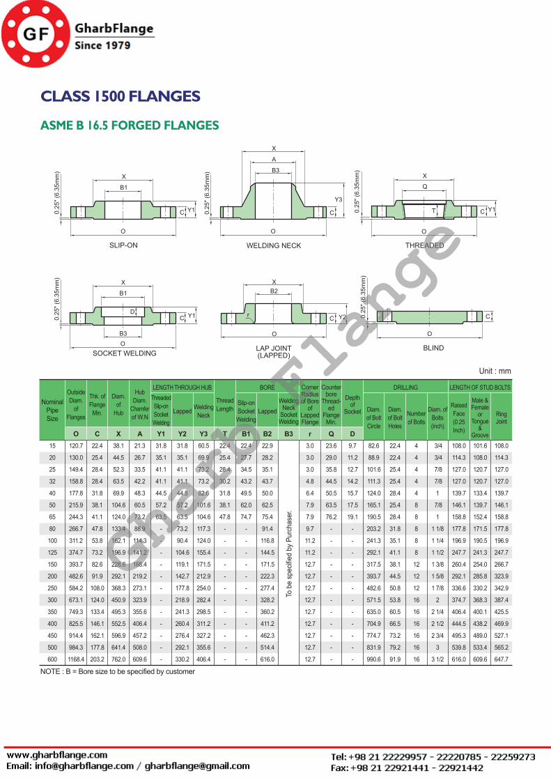
CLASS 1500 FLANGES
ASME B 16.5 FORGED FLANGES
OutsideDiam.
ofFlanges
Thk. ofFlange
Min.
Diam.of
Hub
HubDiam.
Chamferof W.N
ThreadedSlip-onSocketWelding
Lapped WeldingNeck
Slip-onSocketWelding
LappedWelding
NeckSocketWelding
Diam. of BoltCircle
Diam. of BoltHoles
Numberof Bolts
Diam. ofBolts(inch)
RaisedFace(0.25Inch)
Male &Female
orTongue
&Groove
RingJoint
CornerRadiusof Bore
ofLappedFlange
Counterbore
Thread-ed
FlangeMin.
Depthof
Socket
ThreadLength
LENGTH THROUGH HUB BORE DRILLING LENGTH OF STUD BOLTS
O C X A Y1 Y2 Y3 T B1 B2 B3 r Q D
NominalPipeSize
108.0
114.3
127.0
127.0
139.7
146.1
158.8
177.8
196.9
247.7
266.7
323.9
342.9
387.4
425.5
469.9
527.1
565.2
647.7
101.6
108.0
120.7
120.7
133.4
139.7
152.4
171.5
190.5
241.3
254.0
285.8
330.2
368.3
400.1
438.2
489.0
533.4
609.6
108.0
114.3
127.0
127.0
139.7
146.1
158.8
177.8
196.9
247.7
260.4
292.1
336.6
374.7
406.4
444.5
495.3
539.8
616.0
3/4
3/4
7/8
7/8
1
7/8
1
1 1/8
1 1/4
1 1/2
1 3/8
1 5/8
1 7/8
2
2 1/4
2 1/2
2 3/4
3
3 1/2
4
4
4
4
4
8
8
8
8
8
12
12
12
16
16
16
16
16
16
22.4
22.4
25.4
25.4
28.4
25.4
28.4
31.8
35.1
41.1
38.1
44.5
50.8
53.8
60.5
66.5
73.2
79.2
91.9
82.6
88.9
101.6
111.3
124.0
165.1
190.5
203.2
241.3
292.1
317.5
393.7
482.6
571.5
635.0
704.9
774.7
831.9
990.6
9.7
11.2
12.7
14.2
15.7
17.5
19.1
-
-
-
-
-
-
-
-
-
-
-
-
23.6
29.0
35.8
44.5
50.5
63.5
76.2
-
-
-
-
-
-
-
-
-
-
-
-
3.0
3.0
3.0
4.8
6.4
7.9
7.9
9.7
11.2
11.2
12.7
12.7
12.7
12.7
12.7
12.7
12.7
12.7
12.7
22.9
28.2
35.1
43.7
50.0
62.5
75.4
91.4
116.8
144.5
171.5
222.3
277.4
328.2
360.2
411.2
462.3
514.4
616.0
22.4
27.7
34.5
43.2
49.5
62.0
74.7
-
-
-
-
-
-
-
-
-
-
-
-
22.4
25.4
28.4
30.2
31.8
38.1
47.8
-
-
-
-
-
-
-
-
-
-
-
-
60.5
69.9
73.2
73.2
82.6
101.6
104.6
117.3
124.0
155.4
171.5
212.9
254.0
282.4
298.5
311.2
327.2
355.6
406.4
31.8
35.1
41.1
41.1
44.5
57.2
63.5
73.2
90.4
104.6
119.1
142.7
177.8
218.9
241.3
260.4
276.4
292.1
330.2
31.8
35.1
41.1
41.1
44.5
57.2
63.5
-
-
-
-
-
-
-
-
-
-
-
-
21.3
26.7
33.5
42.2
48.3
60.5
73.2
88.9
114.3
141.2
168.4
219.2
273.1
323.9
355.6
406.4
457.2
508.0
609.6
38.1
44.5
52.3
63.5
69.9
104.6
124.0
133.4
162.1
196.9
228.6
292.1
368.3
450.9
495.3
552.5
596.9
641.4
762.0
22.4
25.4
28.4
28.4
31.8
38.1
41.1
47.8
53.8
73.2
82.6
91.9
108.0
124.0
133.4
146.1
162.1
177.8
203.2
120.7
130.0
149.4
158.8
177.8
215.9
244.3
266.7
311.2
374.7
393.7
482.6
584.2
673.1
749.3
825.5
914.4
984.3
1168.4
15
20
25
32
40
50
65
80
100
125
150
200
250
300
350
400
450
500
600
Unit : mm
To b
e sp
ecifie
d by
Pur
chas
er.
NOTE : B = Bore size to be specified by customer
Gharb Flange

Rev. 3. 0 / 2014. 10. 01FLANGES - 18
CLASS 2500 FLANGES
ASME B 16.5 FORGED FLANGES
OutsideDiam.
ofFlanges
Thk. ofFlange
Min.
Diam.of
Hub
HubDiam.
Chamferof W.N
Threaded Lapped WeldingNeck Lapped Welding
NeckDiam. of
BoltCircle
Diam. ofBolt
Holes
Numberof Bolts
Diam. ofBolts
RaisedFace(0.25Inch)
Male &Female
orTongue
&Groove
RingJoint
CornerRadiusof Bore
ofLappedFlange
Counterbore
Thread-ed
FlangeMin.
ThreadLength
LENGTH THROUGH HUB BORE DRILLING LENGTH OF STUD BOLTS
O C X A Y1 Y2 Y3 T B1 B2 r Q
NominalPipeSize
4.75
5.00
5.50
6.00
6.75
7.00
8.00
9.00
10.25
12.25
14.00
15.50
20.00
22.00
4.50
4.75
5.25
5.75
6.50
6.75
7.50
8.50
9.75
11.50
13.25
14.75
19.00
21.00
4.75
5.00
5.50
6.00
6.75
7.00
7.75
8.75
10.00
11.75
13.50
15.00
19.25
21.25
3/4
3/4
7/8
1
1 1/8
1
1 1/8
1 1/4
1 1/2
1 3/4
2
2
2 1/2
2 3/4
4
4
4
4
4
8
8
8
8
8
8
12
12
12
0.88
0.88
1.00
1.12
1.25
1.12
1.25
1.38
1.62
1.88
2.12
2.12
2.62
2.88
3.50
3.75
4.25
5.12
5.75
6.75
7.75
9.00
10.75
12.75
14.50
17.25
21.25
24.38
0.93
1.14
1.41
1.75
1.99
2.50
3.00
-
-
-
-
-
-
-
0.12
0.12
0.12
0.19
0.25
0.31
0.31
0.38
0.44
0.44
0.50
0.50
0.50
0.50
0.90
1.11
1.38
1.72
1.97
2.46
2.97
3.60
4.60
5.69
6.75
8.75
10.92
12.92
1.12
1.25
1.38
1.50
1.75
2.00
2.25
-
-
-
-
-
-
-
2.88
3.12
3.50
3.75
4.38
5.00
5.62
6.62
7.50
9.00
10.75
12.50
16.50
18.25
1.56
1.69
1.88
2.06
2.38
2.75
3.12
3.62
4.25
5.12
6.00
7.00
9.00
10.00
1.56
1.69
1.88
2.06
2.38
2.75
3.12
-
-
-
-
-
-
-
0.84
1.05
1.32
1.66
1.90
2.38
2.88
3.50
4.50
5.56
6.63
8.63
10.75
12.75
1.69
2.00
2.25
2.88
3.12
3.75
4.50
5.25
6.50
8.00
9.25
12.00
14.75
17.38
1.19
1.25
1.38
1.50
1.75
2.00
2.25
2.62
3.00
3.62
4.25
5.00
6.50
7.25
5.25
5.50
6.25
7.25
8.00
9.25
10.50
12.00
14.00
16.50
19.00
21.75
26.50
30.00
1/2
3/4
1
1 1/4
1 1/2
2
2 1/2
3
4
5
6
8
10
12
Unit : inch
To b
e sp
ecifie
d by
Pur
chas
er.
NOTE : B = Bore size to be specified by customer
Gharb Flange
ASME FLANGES
Rev. 3. 0 / 2014. 10. 01 FLANGES - 19
CLASS 2500 FLANGES
ASME B 16.5 FORGED FLANGES
OutsideDiam.
ofFlanges
Thk. ofFlange
Min.
Diam.of
Hub
HubDiam.
Chamferof W.N
Threaded Lapped WeldingNeck Lapped Welding
NeckDiam. of
BoltCircle
Diam. ofBolt
Holes
Numberof Bolts
Diam. ofBolts(inch)
RaisedFace(0.25Inch)
Male &Female
orTongue
&Groove
RingJoint
CornerRadiusof Bore
ofLappedFlange
Counterbore
Thread-ed
FlangeMin.
ThreadLength
LENGTH THROUGH HUB BORE DRILLING LENGTH OF STUD BOLTS
O C X A Y1 Y2 Y3 T B1 B2 r Q
NominalPipeSize
120.7
127.0
139.7
152.4
171.5
177.8
203.2
228.6
260.4
311.2
355.6
393.7
508.0
558.8
114.3
120.7
133.4
146.1
165.1
171.5
190.5
215.9
247.7
292.1
336.6
374.7
482.6
533.4
120.7
127.0
139.7
152.4
171.5
177.8
196.9
222.3
254.0
298.5
342.9
381.0
489.0
539.8
3/4
3/4
7/8
1
1 1/8
1
1 1/8
1 1/4
1 1/2
1 3/4
2
2
2 1/2
2 3/4
4
4
4
4
4
8
8
8
8
8
8
12
12
12
22.4
22.4
25.4
28.4
31.8
28.4
31.8
35.1
41.1
47.8
53.8
53.8
66.5
73.2
88.9
95.3
108.0
130.0
146.1
171.5
196.9
228.6
273.1
323.9
368.3
438.2
539.8
619.3
23.6
29.0
35.8
44.5
50.5
63.5
76.2
-
-
-
-
-
-
-
3.0
3.0
3.0
4.8
6.4
7.9
7.9
9.7
11.2
11.2
12.7
12.7
12.7
12.7
22.9
28.2
35.1
43.7
50.0
62.5
75.4
91.4
116.8
144.5
171.5
222.3
277.4
328.2
28.4
31.8
35.1
38.1
44.5
50.8
57.2
-
-
-
-
-
-
-
73.2
79.2
88.9
95.3
111.3
127.0
142.7
168.1
190.5
228.6
273.1
317.5
419.1
463.6
39.6
42.9
47.8
52.3
60.5
69.9
79.2
91.9
108.0
130.0
152.4
177.8
228.6
254.0
39.6
42.9
47.8
52.3
60.5
69.9
79.2
-
-
-
-
-
-
-
21.3
26.7
33.5
42.2
48.3
60.5
73.2
88.9
114.3
141.2
168.4
219.2
273.1
323.9
42.9
50.8
57.2
73.2
79.2
95.3
114.3
133.4
165.1
203.2
235.0
304.8
374.7
441.5
30.2
31.8
35.1
38.1
44.5
50.8
57.2
66.5
76.2
91.9
108.0
127.0
165.1
184.2
133.4
139.7
158.8
184.2
203.2
235.0
266.7
304.8
355.6
419.1
482.6
552.5
673.1
762.0
15
20
25
32
40
50
65
80
100
125
150
200
250
300
Unit : mm
To b
e sp
ecifie
d by
Pur
chas
er.
NOTE : B = Bore size to be specified by customer
Gharb Flange
Rev. 3. 0 / 2014. 10. 01FLANGES - 20
APPROXIMATE WEIGHT OF FLANGES
FLANGE ASME B 16.5 CLASS 150 CLASS 300
Kg Lb Kg Lb Kg Lb Kg Lb Kg Lb Kg Lb Kg Lb Kg Lb Kg Lb Kg Lb
WELDING-NECK SLIP-ON LAP JOINT THREADED BLIND WELDING-
NECK SLIP-ON LAP JOINT THREADED BLINDSIZE
1/2
3/4
1
1 1/4
1 1/2
2
2 1/2
3
3 1/2
4
5
6
8
10
12
14
16
18
20
24
0.7
0.8
1.1
1.5
1.8
2.7
4.4
5.2
6.4
7.5
9.2
11.0
18.4
25.5
37.0
51.0
61.5
71.5
85.0
119.0
1.5
1.8
2.4
3.3
4.0
6.0
9.8
11.5
14.2
16.6
20.2
24.3
40.6
56.2
81.4
113.0
136.0
158.0
187.0
262.0
0.4
0.7
0.8
1.2
1.4
2.2
3.5
3.8
5.0
5.6
6.5
8.1
13.0
18.4
28.5
37.5
44.5
54.0
72.0
95.0
0.9
1.5
1.8
2.6
3.1
4.8
7.7
8.4
11.0
12.3
14.3
18.0
28.6
40.0
63.0
83.0
98.0
119.0
158.0
209.0
0.4
0.7
0.8
1.1
1.4
2.2
3.5
3.8
5.0
5.6
6.5
8.1
13.0
18.4
28.5
41.5
53.0
59.0
74.0
99.0
0.9
1.5
1.8
2.4
3.1
4.8
7.7
8.4
11.0
12.3
14.3
18.0
28.6
40.0
63.0
91.5
117.0
130.0
163.0
218.0
0.4
0.7
0.8
1.2
1.5
2.3
3.7
4.1
5.1
5.9
7.0
8.4
13.0
18.0
29.0
39.0
47.0
57.0
76.0
97.0
0.9
1.5
1.8
2.6
3.3
5.1
8.1
9.0
11.2
13.0
15.4
18.5
28.6
39.5
64.0
86.0
103.0
126.0
167.0
214.0
0.5
0.8
0.9
1.3
1.6
2.6
4.1
5..1
6.5
7.5
9.2
11.8
20.4
31.0
47.0
60.0
81.0
93.0
127.0
190.0
1.1
1.8
2.0
2.9
3.5
5.7
9.0
11.2
14.3
16.5
20.3
26.0
45.0
68.0
103.0
132.0
178.0
205.0
280.0
419.0
0.8
1.4
1.7
2.2
3.2
3.6
5.4
7.3
8.9
11.8
16.0
20.2
31.2
44.3
63.5
86.0
112.0
141.0
173.0
248.0
1.8
3.1
3.7
4.8
7.0
7.9
12.0
16.1
19.6
26.0
35.2
44.6
68.8
97.5
140.0
190.0
247.0
310.0
382.0
546.0
0.7
1.2
1.4
1.8
2.7
3.2
4.5
5.9
7.5
10
12.5
16.5
25.5
35.0
52.0
73.0
88.0
115.0
139.0
212.0
1.5
2.6
3.1
4.0
6.0
7.0
9.9
13.0
16.5
22.0
27.5
36.4
56.0
77.0
115.0
161.0
194.0
253.0
306.0
467.0
0.7
1.2
1.4
1.8
2.7
3.2
4.5
5.9
7.5
10
12.5
16.5
25.5
35.0
62.0
86.0
113.0
134.0
167.0
240.0
1.5
2.6
3.1
4.0
6.0
7.0
9.9
13.0
16.5
22.0
27.5
36.4
56.0
77.0
137.0
190.0
249.0
295.0
368.0
549.0
0.7
1.2
1.4
1.9
2.8
3.3
4.6
6.3
7.8
10.2
12.9
16.8
26.0
37.5
53.0
73.0
88.0
115.0
139.0
212.0
1.5
2.6
3.1
4.2
6.2
7.3
10.1
13.9
17.2
22.4
28.4
37.0
57.2
82.5
117.0
161.0
194.0
253.0
306.0
467.0
0.8
1.2
1.5
2.0
2.9
3.5
5.3
7.2
9.2
12.2
16.0
22.0
36.0
55.0
82.5
108.0
139.0
178.0
228.0
350.0
1.8
2.6
3.3
4.4
6.4
7.7
11.7
15.9
20.3
26.8
35.2
48.4
79.5
121.0
182.0
238.0
306.0
392.0
503.0
772.0
CLASS 600 CLASS 900
Kg Lb Kg Lb Kg Lb Kg Lb Kg Lb Kg Lb Kg Lb Kg Lb Kg Lb Kg Lb
WELDING-NECK SLIP-ON LAP JOINT THREADED BLINDSIZE
1/2
3/4
1
1 1/4
1 1/2
2
2 1/2
3
3 1/2
4
5
6
8
10
12
14
16
18
20
24
WELDING-NECK SLIP-ON LAP JOINT THREADED BLIND
0.9
1.6
1.9
2.6
3.6
4.7
4.8
8.7
11.6
18.4
31.0
37.0
54.5
98.5
105.0
150.0
177.0
228.0
285.0
372.0
2.0
3.5
4.2
5.8
8.0
10.4
15.0
19.3
25.5
40.5
68.0
81.4
120.0
195.0
231.0
330.0
390.0
503.0
628.0
820.0
0.8
1.4
1.7
2.1
3.1
3.9
5.4
7.3
9.0
16.5
28.5
36.2
51.5
76.2
89.5
102.0
150.0
180.0
231.0
330.0
1.8
3.1
3.7
4.6
6.8
8.6
11.9
16.1
19.8
36..4
62.8
79.8
114.0
168.0
197.0
225.0
330.0
397.0
509.0
727.0
0.8
1.4
1.7
2.1
3.1
3.9
5.4
7.3
9.0
16.1
27.5
35.4
49.5
74.0
89.0
111.0
165.0
194.0
255.0
362.0
1.8
3.1
3.7
4.6
6.8
8.6
11.9
16.1
19.8
35.5
60.6
78.0
109.0
163.0
196.0
245.0
363.0
428.0
562.0
798.0
0.9
1.4
1.8
2.3
3.3
4.0
5.5
7.4
9.2
16.8
28.5
36.2
21.5
76.2
89.5
102.0
150.0
180.0
231.0
330.0
2.0
3.1
4.0
5.0
7.3
8.8
12.1
16.3
20.2
37.0
62.8
79.8
114.0
168.0
197.0
225.0
330.0
397.0
509.0
727.0
0.8
1.4
1.7
2.4
3.4
4.4
6.8
8.9
12.7
18.6
30.8
38.0
62.2
102.0
132.0
158.0
225.0
285.0
365.0
532.0
1.8
3.1
3.7
5.3
7.5
9.7
15.0
19.7
28.0
41.0
68.0
83.6
137.0
225.0
291.0
348.0
496.0
628.0
805.0
1170.0
2.1
2.7
3.9
4.5
6.2
11.3
16.3
15.0
-
24.0
38.5
50.0
85.0
123.0
168.0
198.0
225.0
318.0
376.0
680.0
4.6
5.9
8.6
9.9
13.7
24.9
36.0
33.0
-
52.8
85.0
110.0
187.0
271.0
370.0
436.0
495.0
701.0
829.0
1498.0
1.8
2.4
3.6
4.1
5.4
10.5
15.8
12.3
-
23.2
37.5
48.3
75.0
110.0
146.0
172.0
192.0
272.0
330.0
632.0
4.0
5.3
7.9
9.0
12.0
23.1
34.8
27.0
-
51.0
82.6
106.0
165.0
243.0
322.0
379.0
423.0
600.0
727.0
1393.0
1.8
2.3
3.6
4.1
5.4
10.5
15.8
11.8
-
22.6
36.5
47.5
86.0
124.0
167.0
180.0
210.0
294.0
365.0
700.0
4.0
5.0
7.9
9.0
12.0
23.1
34.8
26.0
-
49.8
80.5
105.0
190.0
273.0
368.0
397.0
463.0
648.0
805.0
1543.0
1.8
2.3
3.6
4.1
5.4
10.5
15.8
12.3
-
23.2
37.5
48.3
75.0
110.0
146.0
172.0
192.0
272.0
330.0
632.0
4.0
5.0
7.9
9.0
12.0
23.1
34.8
27.0
-
51.0
82.6
106.0
165.0
243.0
322.0
379.0
423.0
600.0
727.0
1393.0
1.9
2.7
3.7
4.3
5.9
11.3
16.0
16.8
-
24.5
39.5
51.5
89.0
131.0
187.0
224.0
259.0
383.0
482.0
905.0
4.2
6.0
8.1
9.5
13.0
24.9
35.2
37.0
-
54.0
87.0
113.5
196.0
289.0
412.0
494.0
593.0
844.0
1063.0
1995.0
Gharb Flange
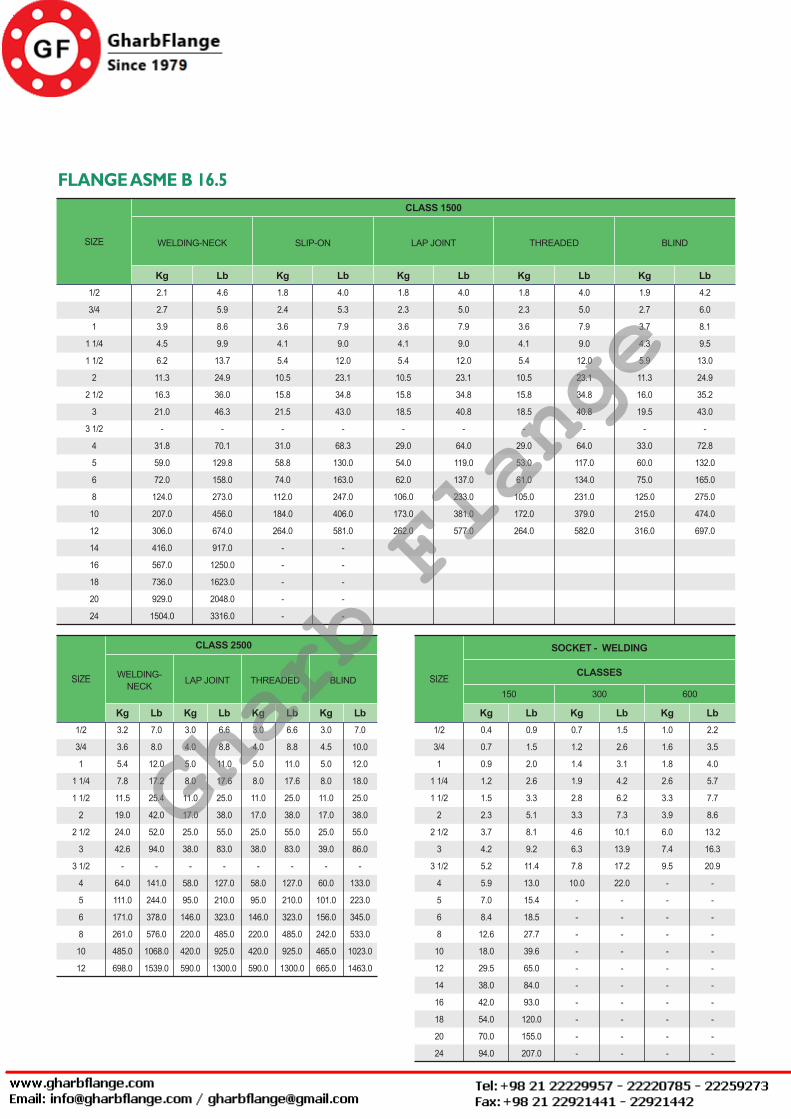
ASME FLANGES
Rev. 3. 0 / 2014. 10. 01 FLANGES - 21
FLANGE ASME B 16.5 CLASS 1500
Kg LbKg LbKg LbKg LbKg Lb
WELDING-NECK SLIP-ON LAP JOINT THREADED BLINDSIZE
1/2
3/4
1
1 1/4
1 1/2
2
2 1/2
3
3 1/2
4
5
6
8
10
12
14
16
18
20
24
2.1
2.7
3.9
4.5
6.2
11.3
16.3
21.0
-
31.8
59.0
72.0
124.0
207.0
306.0
416.0
567.0
736.0
929.0
1504.0
4.6
5.9
8.6
9.9
13.7
24.9
36.0
46.3
-
70.1
129.8
158.0
273.0
456.0
674.0
917.0
1250.0
1623.0
2048.0
3316.0
1.8
2.4
3.6
4.1
5.4
10.5
15.8
21.5
-
31.0
58.8
74.0
112.0
184.0
264.0
-
-
-
-
-
4.0
5.3
7.9
9.0
12.0
23.1
34.8
43.0
-
68.3
130.0
163.0
247.0
406.0
581.0
-
-
-
-
-
1.8
2.3
3.6
4.1
5.4
10.5
15.8
18.5
-
29.0
54.0
62.0
106.0
173.0
262.0
4.0
5.0
7.9
9.0
12.0
23.1
34.8
40.8
-
64.0
119.0
137.0
233.0
381.0
577.0
1.8
2.3
3.6
4.1
5.4
10.5
15.8
18.5
-
29.0
53.0
61.0
105.0
172.0
264.0
4.0
5.0
7.9
9.0
12.0
23.1
34.8
40.8
-
64.0
117.0
134.0
231.0
379.0
582.0
1.9
2.7
3.7
4.3
5.9
11.3
16.0
19.5
-
33.0
60.0
75.0
125.0
215.0
316.0
4.2
6.0
8.1
9.5
13.0
24.9
35.2
43.0
-
72.8
132.0
165.0
275.0
474.0
697.0
CLASS 2500
Kg LbKg LbKg LbKg Lb
WELDING-NECK LAP JOINT THREADED BLINDSIZE
1/2
3/4
1
1 1/4
1 1/2
2
2 1/2
3
3 1/2
4
5
6
8
10
12
3.2
3.6
5.4
7.8
11.5
19.0
24.0
42.6
-
64.0
111.0
171.0
261.0
485.0
698.0
7.0
8.0
12.0
17.2
25.4
42.0
52.0
94.0
-
141.0
244.0
378.0
576.0
1068.0
1539.0
3.0
4.0
5.0
8.0
11.0
17.0
25.0
38.0
-
58.0
95.0
146.0
220.0
420.0
590.0
6.6
8.8
11.0
17.6
25.0
38.0
55.0
83.0
-
127.0
210.0
323.0
485.0
925.0
1300.0
3.0
4.0
5.0
8.0
11.0
17.0
25.0
38.0
-
58.0
95.0
146.0
220.0
420.0
590.0
6.6
8.8
11.0
17.6
25.0
38.0
55.0
83.0
-
127.0
210.0
323.0
485.0
925.0
1300.0
3.0
4.5
5.0
8.0
11.0
17.0
25.0
39.0
-
60.0
101.0
156.0
242.0
465.0
665.0
7.0
10.0
12.0
18.0
25.0
38.0
55.0
86.0
-
133.0
223.0
345.0
533.0
1023.0
1463.0
SOCKET - WELDING
CLASSES
Kg Lb
150SIZE
Kg Lb
300
Kg Lb
600
1/2
3/4
1
1 1/4
1 1/2
2
2 1/2
3
3 1/2
4
5
6
8
10
12
14
16
18
20
24
0.4
0.7
0.9
1.2
1.5
2.3
3.7
4.2
5.2
5.9
7.0
8.4
12.6
18.0
29.5
38.0
42.0
54.0
70.0
94.0
0.9
1.5
2.0
2.6
3.3
5.1
8.1
9.2
11.4
13.0
15.4
18.5
27.7
39.6
65.0
84.0
93.0
120.0
155.0
207.0
0.7
1.2
1.4
1.9
2.8
3.3
4.6
6.3
7.8
10.0
-
-
-
-
-
-
-
-
-
-
1.5
2.6
3.1
4.2
6.2
7.3
10.1
13.9
17.2
22.0
-
-
-
-
-
-
-
-
-
-
1.0
1.6
1.8
2.6
3.3
3.9
6.0
7.4
9.5
-
-
-
-
-
-
-
-
-
-
-
2.2
3.5
4.0
5.7
7.7
8.6
13.2
16.3
20.9
-
-
-
-
-
-
-
-
-
-
-
Gharb Flange
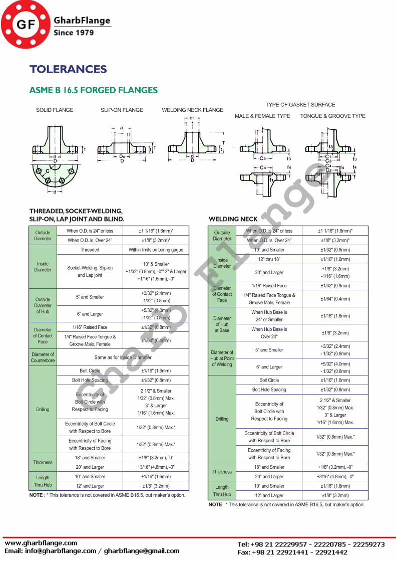
Rev. 3. 0 / 2014. 10. 01FLANGES - 22
TOLERANCES
OutsideDiameter
InsideDiameter
Outside Diameterof Hub
Diameterof Contact
Face
Diameter ofCounterbore
Drilling
When O.D. is 24" or less ±1 1/16" (1.6mm)*
When O.D. is Over 24"
Threaded
Socket-Welding, Slip-onand Lap joint
5" and Smaller
6" and Larger
1/16" Raised Face
1/4" Raised Face Tongue &Groove Male, Female
Same as for Inside Diameter
Bolt Circle ±1/16" (1.6mm)
Bolt Hole Spacing ±1/32" (0.8mm)
Eccentricity of Bolt Circle with
Respect to Facing
2 1/2" & Smaller 1/32" (0.8mm) Max.
3" & Larger 1/16" (1.6mm) Max.
Eccentricity of Bolt Circlewith Respect to Bore
Eccentricity of Facingwith Respect to Bore
18" and Smaller
20" and Larger
10" and SmallerLengthThru Hub
Thickness
12" and Larger
+1/8" (3.2mm), -0"
+3/16" (4.8mm), -0"
±1/16" (1.6mm)
±1/8" (3.2mm)
18" and Smaller
20" and Larger
10" and SmallerLengthThru Hub
Thickness
12" and Larger
+1/8" (3.2mm), -0"
+3/16" (4.8mm), -0"
±1/16" (1.6mm)
±1/8" (3.2mm)
1/32" (0.8mm) Max.*
1/32" (0.8mm) Max.*
±1/32" (0.8mm)
±1/64" (0.4mm)
+3/32" (2.4mm)-1/32" (0.8mm)
+5/32" (4.0mm)-1/32" (0.8mm)
±1/8" (3.2mm)*
Within limits on boring gague
10" & Smaller +1/32" (0.8mm), -0"12" & Larger
+1/16" (1.6mm), -0"
ASME B 16.5 FORGED FLANGES
THREADED, SOCKET-WELDING,SLIP-ON, LAP JOINT AND BLIND.
OutsideDiameter
InsideDiameter
Diameterof Contact
Face
Diameterof Hubat Base
Diameter of Hub at Pointof Welding
Drilling
When O.D. is 24" or less ±1 1/16" (1.6mm)*
When O.D. is Over 24"
10" and Smaller
12" thru 18"
20" and Larger
1/16" Raised Face ±1/32" (0.8mm)
1/4" Raised Face Tongue &Groove Male, Female
When Hub Base is24" or Smaller
When Hub Base isOver 24"
5" and Smaller
6" and Larger
Bolt Circle
Bolt Hole Spacing
Eccentricity of Bolt Circle with
Respect to Facing
Eccentricity of Bolt Circlewith Respect to Bore
Eccentricity of Facingwith Respect to Bore
±1/64" (0.4mm)
±1/16" (1.6mm)
±1/8" (3.2mm)
+3/32" (2.4mm)- 1/32" (0.8mm)
+5/32" (4.0mm)- 1/32" (0.8mm)
±1/16" (1.6mm)
±1/32" (0.8mm)
2 1/2" & Smaller 1/32" (0.8mm) Max.
3" & Larger 1/16" (1.6mm) Max.
1/32" (0.8mm) Max.*
1/32" (0.8mm) Max.*
±1/8" (3.2mm)*
±1/32" (0.8mm)
±1/16" (1.6mm)
+1/8" (3.2mm)-1/16" (1.6mm)
WELDING NECK
NOTE : * This tolerance is not covered in ASME B16.5, but maker’s option.
NOTE : * This tolerance is not covered in ASME B16.5, but maker’s option.
SOLID FLANGE SLIP-ON FLANGE WELDING NECK FLANGETYPE OF GASKET SURFACE
MALE & FEMALE TYPE TONGUE & GROOVE TYPE
Gharb Flange
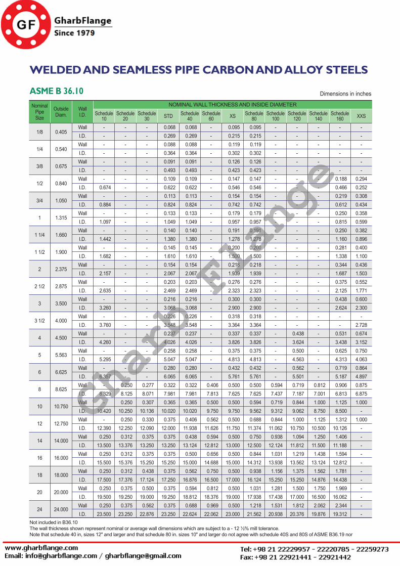
ASME FLANGES
Rev. 3. 0 / 2014. 10. 01 FLANGES - 23
WELDED AND SEAMLESS PIPE CARBON AND ALLOY STEELS
ASME B 36.10Nominal
PipeSize
OutsideDiam.
WallI.D. Schedule
10
NOMINAL WALL THICKNESS AND INSIDE DIAMETERSchedule
20Schedule
30 STD Schedule40
Schedule60 XS Schedule
80Schedule
100Schedule
120Schedule
140Schedule
160 XXS
1/8
1/4
3/8
1/2
3/4
1
1 1/4
1 1/2
2
2 1/2
3
3 1/2
4
5
6
8
10
12
14
16
18
20
24
0.405
0.540
0.675
0.840
1.050
1.315
1.660
1.900
2.375
2.875
3.500
4.000
4.500
5.563
6.625
8.625
10.750
12.750
14.000
16.000
18.000
20.000
24.000
WallI.D.WallI.D.WallI.D.WallI.D.WallI.D.WallI.D.WallI.D.WallI.D.WallI.D.WallI.D.WallI.D.WallI.D.WallI.D.WallI.D.WallI.D.WallI.D.WallI.D.WallI.D.WallI.D.WallI.D.WallI.D.WallI.D.WallI.D.
-------
0.674-
0.884-
1.097-
1.442-
1.682-
2.157-
2.635-
3.260-
3.760-
4.260-
5.295-
6.357-
8.329-
10.420-
12.390 0.25013.500 0.25015.500 0.25017.500 0.25019.500 0.25023.500
------------------------------
0.250 8.125 0.25010.250 0.25012.250 0.31213.376 0.31215.376 0.31217.376 0.37519.250 0.37523.250
------------------------------
0.277 8.071 0.30710.136 0.33012.090 0.37513.250 0.37515.250 0.43817.124 0.50019.000 0.56222.876
0.0680.2690.0880.3640.0910.4930.1090.6220.1130.8240.1331.0490.1401.3800.1451.6100.1542.0670.2032.4690.2163.0680.2263.5480.2374.0260.2585.0470.2806.0650.3227.9810.365
10.0200.375
12.0000.375
13.2500.375
15.2500.375
17.2500.375
19.2500.375
23.250
0.0680.2690.0880.3640.0910.4930.1090.6220.1130.8240.1331.0490.1401.3800.1451.6100.1542.0670.2032.4690.2163.0680.2263.5480.2374.0260.2585.0470.2806.0650.3227.9810.365
10.0200.406
11.9380.438
13.1240.500
15.0000.562
16.8760.594
18.8120.688
22.624
- - - - - - - - - - - - - - - - - - - - - - - - - - - - - -0.4067.8130.5009.7500.562
11.6260.594
12.8120.656
14.6880.750
16.5000.812
18.3760.969
22.062
0.0950.2150.1190.3020.1260.4230.1470.5460.1540.7420.1790.9570.1911.2780.2001.5000.2181.9390.2762.3230.3002.9000.3183.3640.3373.8260.3754.8130.4325.7610.5007.6250.5009.7500.500
11.7500.500
13.0000.500
15.0000.500
17.0000.500
19.0000.500
23.000
0.0950.2150.1190.3020.1260.4230.1470.5460.1540.7420.1790.9570.1911.2780.2001.5000.2181.9390.2762.3230.3002.9000.3183.3640.3373.8260.3754.8130.4325.7610.5007.6250.5949.5620.688
11.3740.750
12.5000.844
14.3120.938
16.1241.031
17.9381.218
21.562
------------------------------
0.594 7.437 0.719 9.312 0.84411.062 0.93812.124 1.03113.938 1.15615.250 1.28117.438 1.53120.938
------------------------
0.438 3.624 0.500 4.563 0.562 5.501 0.719 7.187 0.844 9.062 1.00010.750 1.09411.812 1.21913.562 1.37515.250 1.50017.000 1.81220.376
------------------------------
0.812 7.001 1.000 8.750 1.12510.500 1.25011.500 1.43813.124 1.56214.876 1.75016.500 2.06219.876
------
0.188 0.466 0.219 0.612 0.250 0.815 0.250 1.160 0.281 1.338 0.344 1.687 0.375 2.125 0.438 2.624
--
0.531 3.438 0.625 4.313 0.719 5.187 0.906 6.813 1.125 8.500 1.31210.126 1.40611.188 1.59412.812 1.78114.438 1.96916.062 2.34419.312
------
0.2940.2520.3080.4340.3580.5990.3820.8960.4001.1000.4361.5030.5521.7710.6002.300
-2.7280.6743.1520.7504.0630.8644.8970.8756.8751.000
-1.000
-----------
Dimensions in inches
Not included in B36.10The wall thickness shown represent nominal or average wall dimensions which are subject to a - 12 ½% mill tolerance. Note that schedule 40 in, sizes 12" and larger and that schedule 80 in. sizes 10" and larger do not agree with schedule 40S and 80S of ASME B36.19 norwith standard weight and extra strong respectively
Gharb Flange
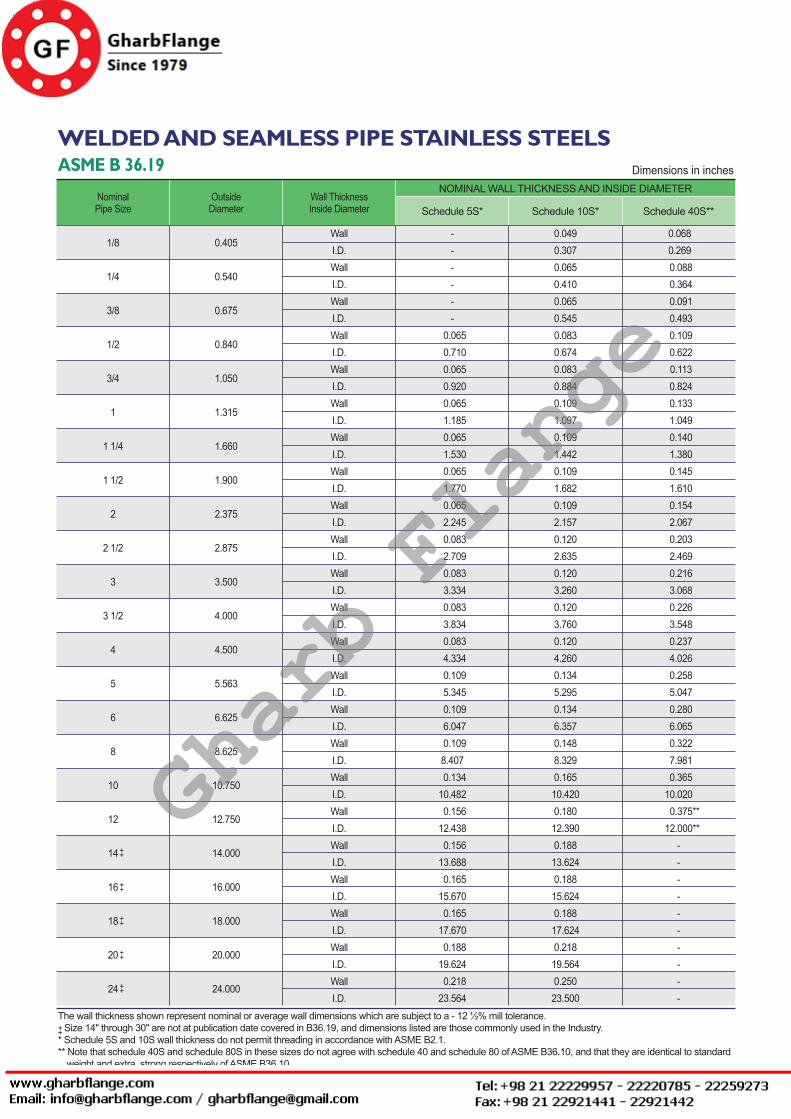
Rev. 3. 0 / 2014. 10. 01FLANGES - 24
WELDED AND SEAMLESS PIPE STAINLESS STEELSASME B 36.19
NominalPipe Size
Outside Diameter
Wall ThicknessInside Diameter
NOMINAL WALL THICKNESS AND INSIDE DIAMETER
Schedule 5S* Schedule 10S* Schedule 40S**
1/8
1/4
3/8
1/2
3/4
1
1 1/4
1 1/2
2
2 1/2
3
3 1/2
4
5
6
8
10
12
14
16
18
20
24
0.405
0.540
0.675
0.840
1.050
1.315
1.660
1.900
2.375
2.875
3.500
4.000
4.500
5.563
6.625
8.625
10.750
12.750
14.000
16.000
18.000
20.000
24.000
WallI.D.WallI.D.WallI.D.WallI.D.WallI.D.WallI.D.WallI.D.WallI.D.WallI.D.WallI.D.WallI.D.WallI.D.WallI.D.WallI.D.WallI.D.WallI.D.WallI.D.WallI.D.WallI.D.WallI.D.WallI.D.WallI.D.WallI.D.
------
0.065 0.710 0.065 0.920 0.065 1.185 0.065 1.530 0.065 1.770 0.065 2.245 0.083 2.709 0.083 3.334 0.083 3.834 0.083 4.334 0.109 5.345 0.109 6.047 0.1098.407 0.13410.482 0.15612.438 0.15613.688 0.16515.670 0.16517.670 0.18819.624 0.21823.564
0.0490.3070.0650.4100.0650.5450.0830.6740.0830.8840.1091.0970.1091.4420.1091.6820.1092.1570.1202.6350.1203.2600.1203.7600.1204.2600.1345.2950.1346.3570.1488.3290.16510.4200.18012.3900.18813.6240.18815.6240.18817.6240.21819.5640.25023.500
0.068 0.269 0.088 0.364 0.091 0.493 0.109 0.622 0.113 0.824 0.133 1.049 0.140 1.380 0.145 1.610 0.154 2.067 0.203 2.469 0.216 3.068 0.226 3.548 0.237 4.026 0.258 5.047 0.280 6.065 0.322 7.981 0.36510.020
0.375** 12.000**
----------
Dimensions in inches
The wall thickness shown represent nominal or average wall dimensions which are subject to a - 12 ½% mill tolerance. Size 14" through 30" are not at publication date covered in B36.19, and dimensions listed are those commonly used in the Industry.* Schedule 5S and 10S wall thickness do not permit threading in accordance with ASME B2.1.** Note that schedule 40S and schedule 80S in these sizes do not agree with schedule 40 and schedule 80 of ASME B36.10, and that they are identical to standard weight and extra strong respectively of ASME B36.10.
++
++
++
++
++
++
Gharb Flange
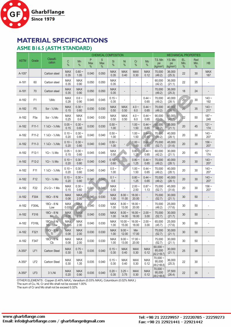
ASME FLANGES
Rev. 3. 0 / 2014. 10. 01 FLANGES - 25
MATERIAL SPECIFICATIONSASME B16.5 (ASTM STANDARD)
ASTM Grade Classifi-cation C
%
CHEMICAL COMPOSITION MECHANICAL PROPERTIES
Mn%
PMax%
SMax%
Si%
Ni%
Cr%
Mo%
T.S. Minpsi
(kg/mm2)
Y.S. Minpsi
(kg/mm2)
EL.Min.%
RedMin.%
HB
A-105* Carbon steel MAX0.35
0.60 ~1.05 0.040 0.050 MAX
0.35MAX0.40
MAX0.30
MAX0.12
70,000(49.2)
36,000(25.3) 22 30 MAX
187
A-181 60 Carbon steel MAX0.35
MAX0.90 0.050 0.050 MAX
0.35 - - - 60,000(42.2)
36,000(21.1) 22 35 -
A-181 70 Carbon steel MAX0.35
MAX0.90 0.050 0.050 MAX
0.35 - - - 70,000(49.2)
36,000(25.3) 18 24 -
A-182 F1 ½Mo MAX0.28
0.6 ~0.90 0.045 0.045 0.15 ~
0.35 - - 0.44 ~0.65
70,000(49.2)
40,000(28.1) 20 30 143 ~
192
A-182
A-182
A-182
A-182
A-182
A-182
A-182
A-182
A-182
A-182
A-182
A-182
A-182
A-182
A-182
A-182
A-350*
A-350*
A-350*
F5
F5a
F11-1
F11-2
F11-3
F12-1
F12-2
F11
F12
F22
F304
F304L
F316
F316L
F321
F347
LF1
LF2
LF3
5cr - ½ Mo
5cr - ½ Mo
1 ¼Cr - ½ Mo
1 ¼Cr - ½ Mo
1 ¼Cr - ½ Mo
1Cr - ½ Mo
1Cr - ½ Mo
1 ¼Cr - ½ Mo
1Cr - ½ Mo
2¼ Cr - 1 Mo
18Cr - 8 Ni
18Cr - 8 NiLow
18Cr - 8 NiMo
18Cr - 8 NiMo - Low
18Cr - 8 NiTi
18Cr - 8 NiCb
Carbon Steel
Carbon Steel
3 ½ Ni
MAX0.15
MAX0.25
0.05 ~0.15
0.10 ~0.20
0.10 ~0.20
0.05 ~0.15
0.10 ~0.20
0.10 ~0.20
0.10 ~0.20
MAX0.15
MAX0.08
MAX0.035
MAX0.08
MAX0.035
MAX0.08
MAX0.08
MAX0.30
MAX0.30
MAX0.20
0.30 ~0.60
MAX0.6
0.30 ~0.60
0.30 ~0.80
0.30 ~0.80
0.30 ~0.60
0.30 ~0.80
0.30 ~0.60
0.30 ~0.80
0.30 ~0.60
MAX2.00
MAX2.00
MAX2.00
MAX2.00
MAX2.00
MAX2.00
0.75 ~1.05
MAX1.35
MAX0.90
0.030
0.040
0.030
0.040
0.040
0.045
0.040
0.040
0.040
0.040
0.030
0.030
0.040
0.040
0.045
0.040
0.040
0.040
0.040
0.030
0.030
0.030
0.030
0.030
0.030
0.040
0.040
0.040
0.040
0.040
0.040
0.040
0.030
0.030
0.035
0.035
0.035
0.030 MAX0.50
MAX0.50
0.50 ~1.00
0.50 ~1.00
0.50 ~1.00
MAX0.50
0.10 ~0.60
0.5 ~1.00
0.1 ~0.6
MAX0.50
MAX1.00
MAX1.00
MAX1.00
MAX1.00
MAX1.00
MAX1.00
0.15 ~0.30
0.15 ~0.30
0.20 ~0.35
MAX0.50
MAX0.50
-
-
-
-
-
-
-
-
8.00 ~11.00
8.00 ~13.00
8.00 ~14.00
10.00 ~15.00
9.00 ~12.00
9.00 ~13.00
MAX0.40
MAX0.40
3.25 ~3.75
4.0 ~6.0
4.0 ~6.0
1.00 ~1.50
1.00 ~1.50
1.00 ~1.50
0.80 ~1.25
0.80 ~1.25
1.00 ~1.50
0.80 ~1.25
2.00 ~2.50
18.00 ~20.00
18.00 ~20.00
16.00 ~18.00
16.00 ~18.00
Min17.00
17.00 ~20.00
MAX0.30
MAX0.30
MAX0.30
0.44 ~0.65
0.44 ~0.65
0.44 ~0.65
0.44 ~0.65
0.44 ~0.65
0.44 ~0.65
0.44 ~0.65
0.44 ~0.65
0.44 ~0.65
0.87 ~1.13
-
-
2.00 ~3.00
2.00 ~3.00
-
-
MAX0.12
MAX0.12
MAX0.12
70,000(49.2)
90,000(63.3)
60,000(42.2)
70,000(49.2)
75,000(52.7)
60,000(42.2)
70,000(49.2)
70,000(49.2)
70,000(49.2)
75,000(52.7)
75,000(52.7)
70,000(49.2)
75,000(52.7)
65,000(45.7)
75,000(52.7)
75,000(52.7)
60,000 ~85,000
(42.2~59.7)70,000 ~95,000
(49.2~66.8)70,000 ~95,000
(49.2~66.8)
40,000(28.1)
65,000(45.7)
30,000(21.1)
40,000(28.1)
45,000(31.6)
30,000(21.1)
40,000(28.1)
40,000(28.1)
40,000(28.1)
45,000(31.6)
30,000(21.1)
25,000(17.6)
30,000(21.7)
25,000(17.6)
30,000(21.1)
30,000(21.1)
30,000(21.1)
36,000(25.3)
37,500(26.4)
20
22
20
20
20
20
20
20
20
20
30
30
30
30
30
30
25
22
22
35
50
45
30
30
45
30
30
30
30
50
50
50
50
50
50
38
30
35
143 ~217
187 ~248
121 ~174
143 ~207
156 ~207
121 ~174
143 ~207
143 ~207
143 ~207
156 ~207
-
-
-
-
-
-
-
-
-
OTHER ELEMENTS : Copper (0.40% MAX), Vanadium (0.03% MAX), Columbium (0.02% MAX.)The sum of Cu, Ni, Cr and Mo shall not be exceed 1.00%The sum of Cr and Mo shall not be exceed 0.32%
Gharb Flange
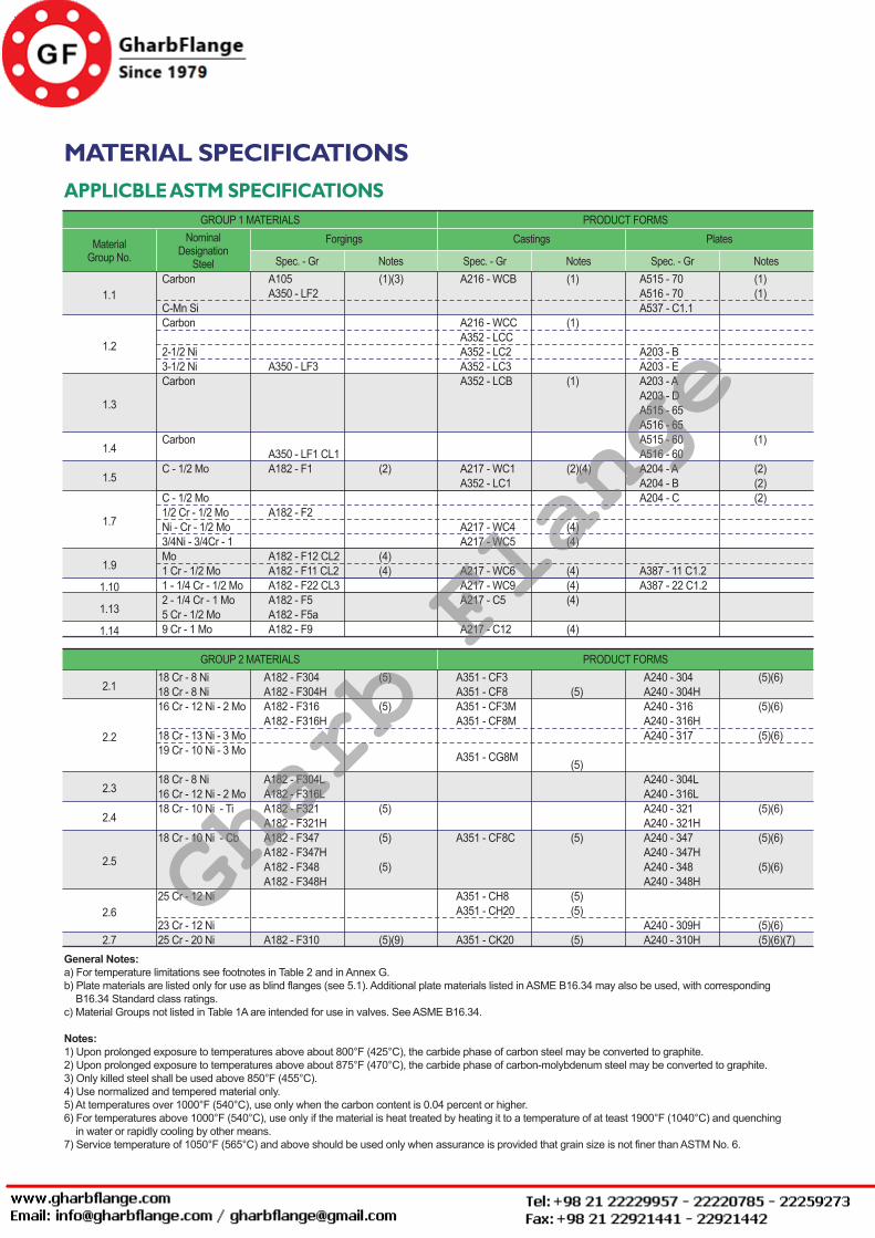
Rev. 3. 0 / 2014. 10. 01FLANGES - 26
MATERIAL SPECIFICATIONSAPPLICBLE ASTM SPECIFICATIONS
MaterialGroup No.
GROUP 1 MATERIALS PRODUCT FORMSNominal
DesignationSteel
Forgings
Spec. - Gr Notes
Castings
Spec. - Gr Notes
Plates
Spec. - Gr Notes
1.1Carbon
C-Mn SiCarbon
2-1/2 Ni3-1/2 NiCarbon
Carbon
C - 1/2 Mo
C - 1/2 Mo1/2 Cr - 1/2 MoNi - Cr - 1/2 Mo3/4Ni - 3/4Cr - 1 Mo1 Cr - 1/2 Mo1 - 1/4 Cr - 1/2 Mo2 - 1/4 Cr - 1 Mo5 Cr - 1/2 Mo9 Cr - 1 Mo
A105A350 - LF2
A350 - LF3
A350 - LF1 CL1A182 - F1
A182 - F2
A182 - F12 CL2A182 - F11 CL2A182 - F22 CL3A182 - F5A182 - F5aA182 - F9
(1)(3)
(2)
(4)(4)
(1)
(1)
(1)
(2)(4)
(4)(4)
(4)(4)(4)
(4)
A515 - 70A516 - 70A537 - C1.1
A203 - BA203 - EA203 - AA203 - DA515 - 65A516 - 65A515 - 60A516 - 60 A204 - AA204 - BA204 - C
A387 - 11 C1.2A387 - 22 C1.2
(1)(1)
(1)
(2)(2)(2)
A216 - WCB
A216 - WCCA352 - LCCA352 - LC2A352 - LC3A352 - LCB
A217 - WC1A352 - LC1
A217 - WC4A217 - WC5
A217 - WC6A217 - WC9A217 - C5
A217 - C12
1.2
1.3
1.4
1.5
1.7
1.9
1.10
1.13
1.14
GROUP 2 MATERIALS PRODUCT FORMS
2.1
2.2
2.3
2.4
2.5
2.6
2.7
18 Cr - 8 Ni18 Cr - 8 Ni16 Cr - 12 Ni - 2 Mo
18 Cr - 13 Ni - 3 Mo19 Cr - 10 Ni - 3 Mo
18 Cr - 8 Ni 16 Cr - 12 Ni - 2 Mo18 Cr - 10 Ni - Ti
18 Cr - 10 Ni - Cb
25 Cr - 12 Ni
23 Cr - 12 Ni 25 Cr - 20 Ni
A182 - F304A182 - F304HA182 - F316A182 - F316H
A182 - F304LA182 - F316LA182 - F321A182 - F321HA182 - F347A182 - F347HA182 - F348A182 - F348H
A182 - F310
(5)
(5)
(5)
(5)
(5)
(5)(9)
A351 - CG8M
A351 - CF3A351 - CF8A351 - CF3MA351 - CF8M
A351 - CF8C
A351 - CH8A351 - CH20
A351 - CK20
(5)
(5)
(5)
(5)(5)
(5)
A240 - 304A240 - 304HA240 - 316A240 - 316HA240 - 317
A240 - 304LA240 - 316LA240 - 321A240 - 321HA240 - 347A240 - 347HA240 - 348A240 - 348H
A240 - 309HA240 - 310H
(5)(6)
(5)(6)
(5)(6)
(5)(6)
(5)(6)
(5)(6)
(5)(6)(5)(6)(7)
General Notes:a) For temperature limitations see footnotes in Table 2 and in Annex G.b) Plate materials are listed only for use as blind flanges (see 5.1). Additional plate materials listed in ASME B16.34 may also be used, with corresponding B16.34 Standard class ratings.c) Material Groups not listed in Table 1A are intended for use in valves. See ASME B16.34.
Notes:1) Upon prolonged exposure to temperatures above about 800°F (425°C), the carbide phase of carbon steel may be converted to graphite.2) Upon prolonged exposure to temperatures above about 875°F (470°C), the carbide phase of carbon-molybdenum steel may be converted to graphite.3) Only killed steel shall be used above 850°F (455°C).4) Use normalized and tempered material only.5) At temperatures over 1000°F (540°C), use only when the carbon content is 0.04 percent or higher.6) For temperatures above 1000°F (540°C), use only if the material is heat treated by heating it to a temperature of at teast 1900°F (1040°C) and quenching in water or rapidly cooling by other means.7) Service temperature of 1050°F (565°C) and above should be used only when assurance is provided that grain size is not finer than ASTM No. 6.
Gharb Flange