Embed Size (px)
Citation preview

1
APPROVED MINUTES May 16, 2013 Standards Committee Meeting
(Changes to the Final Draft by the Action of the Committee Members on 06-20-2013 meeting shown highlighted yellow)
MEMORANDUM July 01, 2013 TO: Standards Committee FROM: Scott Trammell, Secretary RE: Minutes from the May 16, 2013 Standards Committee Meeting A Standards Committee meeting was called to order by Mr. Miller at 9:01 a.m. on May 16, 2013 in the N955 Bay Window Conference Room. The meeting was adjourned at 11:40 a.m. The following committee members were in attendance: Mark Miller, Chairman, Construction Management Director Bob Cales, Contract Administration Division Dave Boruff, Traffic Engineering Division Elizabeth Phillips, Bridges Division Greg Pankow, State Construction Engineer Jim Keefer, Fort Wayne District Construction Director Michael Prather*, Pavement Engineering Michelle Gottschalk, Construction Technical Support Richard Vancleave, Highway Design and Technical Support Division Ron Walker, Materials Management *Proxy for Mike Buening Also in attendance were the following: Scott Seeley Ennis-Flint Traffic Safety Steve Fisher, INDOT Lalit Garg, INDOT Lana Podorvanova, INDOT Kurt Schleter, Gridlock Traffic/ATSSA Dana Plattner, INDOT Steve Johnson, M.A.S. Markers David Holtz, INDOT Brent Johnson, M.A.S. Markers Calvin Lee, ICA Scott Trammell, INDOT Tom Brennan, JTRP Wendy Chiles, INDOT Joe Bruno, INDOT Steve Bates, TECHNITE Corp. Tim McNelis, Indiana SB

2
The following items were listed for consideration. A. GENERAL BUSINESS ITEMS OLD BUSINESS At the end of the meeting, Mr. Prather has mentioned that the RSP 612-R-611, previously approved by the committee at the February 21, 2013 meeting and later withdrawn by Mr. Buening at the March 21, 2013 meeting pending further review regarding the cement grout option, has been revised and ready for use. It was decided that mentioned RSP will go into effect September 01, 2013 and Mr. Miller advised to revise minutes from March 21, 2013 meeting to reflect these changes. NEW BUSINESS (No items were listed for consideration) B. CONCEPTUAL PROPOSAL ITEMS OLD BUSINESS (No items were listed for consideration) NEW BUSINESS (No items were listed for consideration) C. STANDARD SPECIFICATIONS, SPECIAL PROVISIONS AND STANDARD DRAWINGS PROPOSED ITEMS OLD BUSINESS Item No. 19 02/21/13 (2012 SS) Mr. Boruff pg 04 807.13 Luminaire Installation 807.19 Basis of Payment 920.01(d) Luminaires ACTION: PASSED AS REVISED NEW BUSINESS Item No. 01 05/16/13 (2012 SS) Mr. Boruff pg 43 801.02 Materials 801.15 Electronic Devices 801.18 Basis of Payment 923.07 Automated Flagger Assistance Device ACTION: PASSED AS REVISED Item No. 02 05/16/13 (2012 SS) Mr. Boruff pg 49 Recurring Special Provisions: 805-X-XXX MAGNETOMETERS AND MICROLOOP DETECTORS 805-X-XXX RADIO INTERCONNECTION ACTION: PASSED AS SUBMITTED

3
Item No. 03 05/16/13 (2012 SS) Mr. Boruff pg 57 XXX-X-XXX LONGITUDINAL RUMBLE STRIPES 606-R-563 MILLED CENTERLINE CORRUGATIONS 606-R-563d MILLED CENTERLINE CORRUGATIONS 808-MLRS-01 CENTERLINE LONGITUDINAL RUMBLE STRIPE 808-MLRS-02 EDGELINE LONGITUDINAL RUMBLE STRIPE 808-MLRS-03 LONGITUDINAL RUMBLE STRIPES AT INTERSECTION, DRIVE, OR RAILROAD CROSSING ACTION: PASSED AS REVISED Item No. 04 05/16/13 (2012 SS) Mr. Keefer pg 78 805.15 Method of Measurement ACTION: PASSED AS SUBMITTED cc: Committee Members FHWA ICA
Mr. Boruff Date: 05/16/13
SPECIFICATION, SPECIAL PROVISIONS AND DRAWINGS (OLD BUSINESS ITEM) REVISION TO STANDARD SPECIFICATIONS
4
PROPOSAL TO STANDARDS COMMITTEE
PROBLEM(S) ENCOUNTERED: The use of light source types (e.g. LED, plasma) other than High Pressure Sodium (HPS) for roadway and high mast luminaires is now viable and may result in reduced energy consumption. Design procedures are lacking to support consideration of these various light source types and to determine which is the most cost effective for a particular project. Additionally the standard specifications are based on HPS. PROPOSED SOLUTION: Revise the Indiana Design Manual to require a cost analysis of the various light source types and develop a RSP that will supersede the relevant sections of the standards specifications APPLICABLE STANDARD SPECIFICATIONS: 807.03, 807.13; 807.14; 807.19; 920.01(d) APPLICABLE STANDARD DRAWINGS: APPLICABLE DESIGN MANUAL SECTION: Chapter 78-3.04; 78-5; 78-6; 78-7 APPLICABLE SECTION OF GIFE: APPLICABLE RECURRING SPECIAL PROVISIONS: PAY ITEMS AFFECTED: Roadway Luminaire, High Mast Luminaire Submitted By: Dave Boruff Title: Manager, Traffic Administration Section Organization: INDOT Phone Number: 317-234-7975 Date: 03/25/13 APPLICABLE SUB-COMMITTEE ENDORSEMENT: Traffic Standards Subcommittee, Industry.

Item No.19 02/21/13 (2012 SS) (contd.) Mr. Boruff Date: 05/16/13 REVISION TO STANDARD SPECIFICATIONS (OLD BUSINESS ITEM) SECTION 807 – HIGHWAY ILLUMINATION 807.13 LUMINAIRE INSTALLATION 807.19 BASIS OF PAYMENT SECTION 920 – HIGHWAY ILLUMINATION MATERIALS 920.01(d) LUMINAIRES
5
The Standard Specifications are revised as follows: SECTION 807, BEGIN LINE 41, INSERT AS FOLLOWS: 807.03 Working Drawings Working drawings shall be submitted in accordance with 105.02 for lighting-standard assemblies, luminaires, and external drive assemblies. Working drawings for each luminaire model submitted shall include: (a) Test report indicating compliance with ANSI C136.31 2G or 3G
requirements. (b) Test report indicating that IP 66 requirements are met. For solid state and plasma luminaires the working drawings shall also include: (a) IESNA LM - 79 test report. (b) IESNA LM - 80 test report, for solid state luminaries only. (c) Test report verifying ANSI/IEEE C62.41.2 compliance. (d) UL 1449 certification. (e) UL 1283 certification. (fe) Test report indicating Title 47 CFR Part 15, Class A compliance. Certifications and test reports shall be issued by an independent laboratory. Working drawings for luminaires shall also include the Illumination Engineering Society of North America, IESNA, photometric distribution file if the file number varies from what is indicated on the plans. The IESNA photometric distribution file shall be in either ILLUMS, developed by General Electric, or Visual, developed by Acuity Brands Lighting. SECTION 807, BEGIN LINE 526, DELETE AND INSERT AS FOLLOWS: 807.13 Luminaire Installation (a) Installation Luminaire installation shall consist of the physical placing of the luminaire. Each installation shall include the furnishing and placing of the lamp light source as designated. Luminaires shall be compatible with other lighting materials as specified in 920.01. All luminaries on a contract shall be of the same technology and be provided by one manufacturer.

Item No.19 02/21/13 (2012 SS) (contd.) Mr. Boruff Date: 05/16/13 REVISION TO STANDARD SPECIFICATIONS (OLD BUSINESS ITEM) SECTION 807 – HIGHWAY ILLUMINATION 807.13 LUMINAIRE INSTALLATION 807.19 BASIS OF PAYMENT SECTION 920 – HIGHWAY ILLUMINATION MATERIALS 920.01(d) LUMINAIRES
6
(a) 1. Roadway Luminaires Each luminaire shall be leveled in both directions in the horizontal plane after the light standard has been erected and adjusted. Rotary adjustment of the mast arm and vertical adjustment of roadway luminaires to obtain an installed level position in both directions shall be accomplished by means of the bolted saddle arrangement used to attach the luminaires to the mast arm. Lamp socket positions may be shown on the plans by type of Illuminating Engineering Society of North American, (IES), light pattern. The specified lamp socket position, or comparable arrangement of LEDs shall be used to obtain the desired light pattern delivery. Proper connections shall be made to provide ballast operation at the voltage being supplied. Replacements needed because of faulty or incorrect voltage connections shall be made with no additional payment. (b) 2. Sign Luminaires Connections in which plain and galvanized steel are in contact shall be protected such that aluminum surfaces shall receive 1one coat of zinc chromate primer. Steel surfaces shall receive 1one coat of inorganic zinc primer followed by 1one coat of aluminum paint be prepared in accordance with 619.08(a), 619.08(b) and 619.08(d) and painted with a structural steel system in accordance with 619.09(a). All paint shall be permittedallowed to drycure before assembly. Conduit fittings, if required, shall be watertight. Required conduit shall be either rigid or flexible as necessary. Conduit shall not be clamped to a sign panel. Sign luminaires shall be mounted on overhead sign structures on 2two metal channels located at the extremity of the sign walkway support brackets. The distance between lighting unit support channels shall be 7 in. (180 mm). These channels shall be located in such a manner that they readily receive the mounting bolts from the rear of the sign luminaire. The installation of the sign luminaire shall consist of the physical placement of the luminaire on the channels. Sign luminaires shall be connected to a phase conductor and a neutral conductor. The luminaires shall be alternately connected to opposite phase conductors to balance the load. The connections in the base of the sign structure shall be in accordance with 807.06. Conductor splicing shall be in junction boxes, in-ground handholes, inside handholes of sign structures, and circuit breaker enclosures. (c) 3. Underpass Luminaires Underpass luminaires shall be mounted on the vertical side surfaces of bridge bent structures or suspended by means of pendants supported by angle-iron struts or clips fastened to the structural beam members of the bridge. All parts of the pendent pipe assembly shall be hot-dipped galvanized after threads are cut. Silicone caulking compound shall be applied to the threads during assembly of the pendent. Underpass

Item No.19 02/21/13 (2012 SS) (contd.) Mr. Boruff Date: 05/16/13 REVISION TO STANDARD SPECIFICATIONS (OLD BUSINESS ITEM) SECTION 807 – HIGHWAY ILLUMINATION 807.13 LUMINAIRE INSTALLATION 807.19 BASIS OF PAYMENT SECTION 920 – HIGHWAY ILLUMINATION MATERIALS 920.01(d) LUMINAIRES
7
luminaires may require separately mounted ballasts which shall be installed in close proximity to the luminaires. Underpass luminaires shall be connected to a phase conductor and a neutral conductor. The luminaires shall be alternately connected to opposite phase conductors to balance the load. Conductor splicing will only be allowed in junction boxes, in-ground handholes, and circuit breaker enclosures. (d) 4. High Mast Luminaires The aiming of the luminaires shall be as shown on the plans. When the aiming process is being done the luminaire shall be oriented to conform to its raised position and the ring properly tethered to prevent rotation during the aiming adjustment. The long axis of the luminaire shall be parallel to the aiming direction indicated on the plans. (b) Warranty The manufacturer’s written warranty covering all components, except lamps, of the luminaire against defects in materials and workmanship for a minimum period of five years after installation shall be provided. The warranty shall stipulate that replacement luminaires will be provided within seven days after receipt of failed luminaires at no additional cost. Warranty documents shall give the manufacturer’s name, contact person, and contact person telephone number and e-mail and shall be submitted to the Engineer with the Type C Certification. 807.14 Sign, Underpass, Roadway, and High Mast Lighting Location and Luminaire Identification All high mast towers, roadway light standards, underpass lighting installations, and sign lighting installations shall have an identification code number as shown on the plans. In addition, each luminaire at a sign or underpass installation shall be individually identified with a single capital letter. The code number shall be displayed on the light standard, sign structure column, and high mast tower as shown on the plans. The underpass code number shall be displayed near the breaker box at a location as directed. The code number for the lighting standard and sign structure column shall be applied to the pole, as specified by the manufacturer, by using individual, pressure sensitive, adhesive backed tags. The code number for the high mast tower shall be applied to an aluminum plate which is mounted with spacers away from the structure as shown on the plans. A luminaire identification sticker shall be provided on each luminaire and on the light pole or tower that supports the luminaire. The sticker shall be titled “LUMINAIRE”

Item No.19 02/21/13 (2012 SS) (contd.) Mr. Boruff Date: 05/16/13 REVISION TO STANDARD SPECIFICATIONS (OLD BUSINESS ITEM) SECTION 807 – HIGHWAY ILLUMINATION 807.13 LUMINAIRE INSTALLATION 807.19 BASIS OF PAYMENT SECTION 920 – HIGHWAY ILLUMINATION MATERIALS 920.01(d) LUMINAIRES
8
and contain the following information: light source type, manufacturer, model, wattage, and date of installation. The pole/tower sticker shall be attached underneath the light pole ID tag, shall face the roadway, and shall have 3/4 in. lettering, and be no greater than 8 in. by 8 in. SECTION 807, BEGIN LINE 789, DELETE AND INSERT AS FOLLOWS: Payment will be made under: Pay Item Pay Unit Symbol Cable, Pole Circuit, THWH, No. _____ Copper, Stranded, _____ _____/C ................................................................................. LFT (m) Cable-Duct Marker .................................................................................... EACH Circuit Installation, Str. No. _____, _____ Luminaires ............................ EACH no. Conduit, Steel, Galvanized, 2 in. (50 mm) ............................................. LFT (m) Connector Kit, Fused ................................................................................ EACH Connector Kit, Unfused ............................................................................ EACH Handhole, Lighting ................................................................................... EACH High Mast Tower Winch Drive................................................................. EACH Insulation Link, Non-Waterproofed .......................................................... EACH Insulation Link, Waterproofed .................................................................. EACH Light Pole, High Mast, _____ ft (m) E.M.H. ............................................ EACH Light Pole, Roadway, _____ ft (m) E.M.H., _____ ft (m) Mast Arm, _____ Base .................................................. EACH Light Structure, Remove ........................................................................... EACH Lighting Foundation, Concrete, with Grounding, _____ in. (mm) x _____ in. (mm) x _____ in. (mm).......................... EACH Luminaire, High Mast, _____________, _____Watt ............................... EACH light source type type Luminaire, Roadway, _____________, _____ Watt ................................ EACH light source type type Luminaire, Sign, _____________, _____ Watt ........................................ EACH light source type type Luminaire, Underpass, _____________, _____ Watt .............................. EACH light source type type Multiple Compression Fitting, Non-Waterproofed ................................... EACH Multiple Compression Fitting, Waterproofed ........................................... EACH Portable Tower Lighting Drive System .................................................... EACH Service Point, _____ ................................................................................. EACH type Sign, Underpass, and Roadway Lighting Location Identification ............ EACH

Item No.19 02/21/13 (2012 SS) (contd.) Mr. Boruff Date: 05/16/13 REVISION TO STANDARD SPECIFICATIONS (OLD BUSINESS ITEM) SECTION 807 – HIGHWAY ILLUMINATION 807.13 LUMINAIRE INSTALLATION 807.19 BASIS OF PAYMENT SECTION 920 – HIGHWAY ILLUMINATION MATERIALS 920.01(d) LUMINAIRES
9
Wire, ________, No. _____ Copper, in _____, _____ _____ /C .......... LFT (m) designation housing The cost of lamps, LED arrays, plasma emitters, ballast, drivers, optical systems, weatherproof housings, surge protection devices, and electrical connections shall be included in the cost of luminaire. SECTION 920, BEGIN LINE 509, DELETE AND INSERT AS FOLLOWS: (d) Luminaires 1. General Requirements Lamps supplied for luminaires shall be electrically compatible with the luminaires. Luminaires that are not solid state shall include the lamp ballast. The ballast shall be integrally built in and of the constant wattage regulator type of sufficient size to operate the designated lamp at the required voltage. The ballast shall provide satisfactory lamp performance to 20°F (-7°C) The luminaire shall operate satisfactorily in temperatures from - 40°F to 122°F with an input voltage variation of ± 10% of the rated operating voltage specified. Luminaires shall be a single, self contained device, not requiring on-site assembly for installation. Power consumption, wattage, shall not exceed that which is indicated on the plans. Luminaires shall include vandal shields when installed on an underpass or signs on bridge brackets and when otherwise specified. The vandal shield shall be made of a tough durable plastic, such as Lexan, mounted in a rugged galvanized steel or aluminum frame, and shall withstand severe impact without being damaged or allowing the refractor to be damaged. It shall be fastened securely to the luminaire so it cannot be removed from the outside and shall not interfere with the light distribution pattern. It shall protect the face of the refractor and if ventilation is necessary, the ventilating apertures shall be arranged so that they do not admit a probe of a diameter greater than 1/4 in. (6 mm). 2. Roadway Lighting Luminaires Roadway lighting luminaires shall have a precision-cast aluminum housing and refractor holder with weatherproof finish. They shall have a strong, easily operated, positive latch on the street side of the refractor holder housing with and a hinge with and a safety catch that prevents accidental unhinging on the house side of the refractor or lens holder. They shall include a slipfitter capable of adapting to a 2 in. (50 mm) mounting bracket that is adjustable ± 5° for leveling. an easily detachable highly specular aluminum reflector; and an easily adjustable socket in both horizontal and vertical directions capable of producing lighting patterns to meet all the requirements of the American Standard Practice for Roadway Lighting as sponsored by the Illumination Engineering Society and as shown on the plans. They shall have a high impact, heat-resistant, glass, prismatic refractor; and They shall include gasketing that will completely

Item No.19 02/21/13 (2012 SS) (contd.) Mr. Boruff Date: 05/16/13 REVISION TO STANDARD SPECIFICATIONS (OLD BUSINESS ITEM) SECTION 807 – HIGHWAY ILLUMINATION 807.13 LUMINAIRE INSTALLATION 807.19 BASIS OF PAYMENT SECTION 920 – HIGHWAY ILLUMINATION MATERIALS 920.01(d) LUMINAIRES
10
seal out dust, moisture, and insects from the interior of the optical assembly in accordance with IP 66 and retard the formation of an undesirable film from gaseous vapors on the interior of the optical assembly. Internal components shall be adequately supported to withstand mechanical shock and vibration and shall be tested in accordance with ANSI C136.31, 2G loading or ANSI C136.31 3G loading for luminaires on bridges. Luminaire weight shall not exceed 53 lbs and its projected area shall not exceed 2.4 sq ft. Luminaires shall be either High Pressure Sodium, HPS, or utilize another light source in accordance with 920.01 (d) 2.b. a. High Pressure Sodium Luminaires HPS luminaires shall have a high impact, heat-resistant, glass, prismatic refractor; a precision-cast, aluminum refractor holder with weatherproof finish, a detachable highly specular aluminum reflector; and an adjustable socket in both horizontal and vertical directions capable of producing lighting patterns to meet all the requirements of the American Standard Practice for Roadway Lighting as sponsored by the IESNA and as shown on the plans. b. Other Light Source Types Luminaires that utilize technologies other than HPS shall be compatible with the lighting materials specified in this section and in the plans. Luminaires, including primary fuse protection, surge protection devices, and other major components, shall be rated for a minimum operational life of 50,000 hours. Luminaires shall be adjustable in the horizontal and vertical directions to meet the specified IESNA light distribution pattern. Refractors or lenses shall be scratch resistant and made from high impact, heat-resistant, glass or UV inhibited, high impact plastic. If utilized, reflectors shall be detachable and made of highly specular aluminum. Power supply drivers, LED arrays, and plasma emitters shall be replaceable without replacing the entire luminaire. LEDs shall be connected so that the loss of one LED will not result in the loss of the entire luminaire. LED circuitry shall prevent flickering to the unaided eye at the voltage specified on the plans and the range indicated herein. Solid Sstate and plasma luminaires shall meet these additional requirements: (1) Wattage. The wattage shall be verified by the IESNA LM-79
test. (2) Lumen Output. The total lumen output shall meet or exceed the
amount specified on the plans and shall be verified by the IESNA LM-79 test. The luminaire LEDs shall deliver a minimum of 70% of the initial rated lumens after 50,000 hours

Item No.19 02/21/13 (2012 SS) (contd.) Mr. Boruff Date: 05/16/13 REVISION TO STANDARD SPECIFICATIONS (OLD BUSINESS ITEM) SECTION 807 – HIGHWAY ILLUMINATION 807.13 LUMINAIRE INSTALLATION 807.19 BASIS OF PAYMENT SECTION 920 – HIGHWAY ILLUMINATION MATERIALS 920.01(d) LUMINAIRES
11
of operation at 130°F ambient temperature as indicated by LM-80 lumen maintenance test of the light source (L70 > 50,000 hrs).
(3) Chromaticity. Luminaires shall exhibit a color temperature in
the range 4100K to 6,500K per ANSI C78.377 and as verified by the IESNA LM-79 test
(4) Surge Protection. Solid State luminaires shall include a Surge
Protection Device, SPD, to protect the luminaire from damage and failure for transient voltage and currents. The SPD shall conform to UL 1449 and UL 1283 and shall be tested per the procedure in ANSI/IEEE C62.41.2 definitions for standard and optional waveform for location category C-High.
(5) Electromagnetic Interference. Luminaires shall comply with
Title 47 CFR Part 15, Class A on unlicensed transmissions in a business, industrial, commercial, or industrial environment.
(6) Heat Dissipation. A passive thermal management system to
dissipate the heat generated by operation shall be provided- fans or other mechanical cooling systems shall not be used.
3. Sign Luminaires Luminaires shall be 250W mercury vapor metal halide unless otherwise specified. Sign luminaires shall have the same requirements as roadway luminaires plus a shield that blocks the view of the refractor from an approaching motorist. This shall be accomplished by the design of the housing or by a shield fabricated from sheet aluminum, approximately 0.05 in. (1.3 mm) thick, and of sufficient size to be fastened onto the horizontal edge of the refractor holder with self tapping screws and placed between the refractor and approaching traffic. Aluminum and steel structural members for luminaire supports shall include aluminum conduit, conduit clamps, fittings, and stainless steel screws. 4. Underpass Luminaires Underpass luminaires shall have the same requirements as roadway luminaires except they shall have vandal shields and the ballast shall meet the same requirements except it may be mounted separately near the luminaire as shown on the plans. 5. High Mast Luminaires
Item No.19 02/21/13 (2012 SS) (contd.) Mr. Boruff Date: 05/16/13 REVISION TO STANDARD SPECIFICATIONS (OLD BUSINESS ITEM) SECTION 807 – HIGHWAY ILLUMINATION 807.13 LUMINAIRE INSTALLATION 807.19 BASIS OF PAYMENT SECTION 920 – HIGHWAY ILLUMINATION MATERIALS 920.01(d) LUMINAIRES
12
The luminaires shall be in accordance with the American Standard Practice for Roadway Lighting by the Illumination Engineering Society and shall produce lighting patterns as shown on the plans. The lamp in the high mast luminaire lamp or light source shall be supported at both ends with mechanical spring grips or other means to hold the lamp secure against vibration. The Ssockets shall be mogul sized and porcelain enclosed. The luminaire housing shall be an enclosed aluminum unit with a reflector and borosilicate glass refractor or lens. It shall include gasketing that will completely seal out dust, moisture, and insects from the interior of the optical assembly and retard the formation of an undesirable film from gaseous vapors on the optical assembly. High pressure sodium luminaires shall have an aluminum reflector. A high mast luminaire LED retrofit inserted into the existing housing may utilize a mechanical cooling system which is rated for a minimum operational life of 50,000 hrs. High mast luminaires utilizing light sources other than HPS shall meet the requirements of 920.01(d)1 and 920.01(d)2.
Item No.19 02/21/13 (2012 SS) (contd.) Mr. Boruff Date: 05/16/13 REVISION TO STANDARD SPECIFICATIONS (OLD BUSINESS ITEM) BACKUP 01. DESIGN MEMORANDUM (DRAFT)
13
X X
INDIANA DEPARTMENT OF TRANSPORTATION Driving Indiana’s Economic Growth Design Memorandum No. xx-__ Technical Advisory
January 28, 2013 DRAFT
DESIGN MEMORANDUM No. xx-__ TECHNICAL ADVISORY TO: All Design, Operations, District Personnel, and Consultants FROM: _______________________ David Boruff Manager, Office of Traffic Administration Traffic Engineering Division SUBJECT: Lighting Design Procedure REVISE: Indiana Design Manual Section 78-3.04, 78-5, 78-6, and 78-7. EFFECTIVE: To Be Determined Through this time INDOT has been using High Pressure Sodium roadway, high mast, and underpass luminaires. With developing technology other types of light sources (e.g. LED, plasma, induction) are now available and can provide acceptable light levels while reducing energy consumption. Due to varying photometric (light distribution) patterns, installation costs and maintenance schedules it is necessary for the designer to consider and compare various light source types to generate the optimal, most cost effective design Therefore, the subject Indiana Design Manual sections have been revised and two new worksheets, figures 78-5B and 78-5C, have been developed to facilitate the light source type selection process. Please note that sections 807.13, 807.19, and 920.01(d) of the INDOT Standard Specifications are being revised through a recurring special provision to compliment the use of light sources other than HPS as determined and specified by the designer.

Item No.19 02/21/13 (2012 SS) (contd.) Mr. Boruff Date: 05/16/13 REVISION TO STANDARD SPECIFICATIONS (OLD BUSINESS ITEM) BACKUP 01. DESIGN MEMORANDUM (DRAFT)
14
78-3.04 Luminaire A luminaire is defined as a complete lighting unit consisting of a lamp or lamps together with the parts designed to distribute light. The following and the INDOT Standard Specifications provide the Department’s criteria for luminaire hardware. Section 78-6.03 discusses the various light distributions for a luminaire. For additional information, the designer should contact the Highway Operations Division’s Office of Traffic Engineering Traffic Administration Manager, Traffic Engineering Division for the latest products and specifications. 78-3.04(01) Light Source There are numerous light sources for highway lighting. However, there are only a few practical choices when considering availability, size, power requirements, and cost effectiveness. Only a high-intensity discharge light source should be used. The following provides information on the recommended light sources that may be used. 1. High-Pressure Sodium (HPS). Due to its excellent luminous efficiency, power
usage, and long life, HPS is the only light source that INDOT is using for each new installations of conventional or high-mast lighting. The HPS lamp produces a soft, pinkish-yellow light by passing an electric current through a sodium-and-mercury vapor.
2. Low-Pressure Sodium (LPS). Low-pressure sodium is considered one of the most
efficient light sources. Its disadvantage is that it requires long tubes and has poor color quality. INDOT does not allow the use of LPS in a State-controlled system. However, a local agency may consider the use of an LPS lighting source. The LPS lamp produces a yellow light by passing an electrical current through a sodium vapor.
3. Mercury Vapor (MV). Prior to the introduction of HPS, mercury vapor was the
most commonly used light source. A local agency may still install the MV light source for a new installation to match an existing installation. However, INDOT does not allow the use of MV for conventional or high-mast lighting in a new installation. MV usage by INDOT is limited to overhead-sign lighting. The mercury-vapor lamp produces a bluish white light. New installations of Mercury Vapor lamps are prohibited by the Energy Policy Act of 2005.
4. Metal Halide (MH). A metal-halide lamp produces better color at higher
efficiency than an MV lamp. However, life expectancy for an MH lamp is shorter than for HPS or MV. An MH lamp is also more sensitive to lamp orientation than another light source. The MH lamp is used for lighting a sports arena or major sports stadium, for high-mast lighting, or for lighting a downtown area or park.

Item No.19 02/21/13 (2012 SS) (contd.) Mr. Boruff Date: 05/16/13 REVISION TO STANDARD SPECIFICATIONS (OLD BUSINESS ITEM) BACKUP 01. DESIGN MEMORANDUM (DRAFT)
15
Metal halide produces good color rendition. Light is produced by passing a current through a combination of metallic vapors.
5. Light Emitting Diode (LED). LEDs are arranged in clusters which are attached to a panel. Various designs utilize different LED types Heat sinks are built into the housing to facilitate heat dissipation and maximize luminaire service life. Light is directly emitted from the lens, so reflectors are not required, resulting in the light being delivered more efficiently than the HPS type and also resulting in less light pollution. LEDs are energy efficient, have a long life, and produce a “truer” color of light. Due to the manner in which light is emitted the arrays must be carefully arranged to provide sufficient light distribution and yet be energy efficient. Properly arranged LEDs can provide energy efficient, effective light distribution.
LED retrofits are available for existing high mast luminaires. LED modules are attached to a threaded rod which is fit into the existing housing. Luminaire dimensions should be verified as housing diameters less than 16 inches may require an attachment plate as well as the threaded rod, pending the retrofit manufacturer’s specific design.
6. Plasma. Plasma lamps generate light by exciting gas with radio frequency
power. They have no electrodes which reduces maintenance requirements. They are highly efficient and generate a truer color light than HPS.
7. Induction Lighting. Magnetic induction lamps also contain no electrodes resulting in an extended service life. The power used to generate light is transferred from outside the lamp to inside via electromagnetic fields. Induction lamps are also efficient light generators compared to HPS lamps.
78-3.04(02) Optical System The optical system consists of a light source, usually a reflector, and usually a refractor. The following discusses the optical system of a luminaire.
1. Light Source. Section 78-3.04(01) discusses the recommended high-intensity light
sources that should be considered may be used. 2. Reflector. The reflector is used in optical control to change the direction of the
light rays. Its purpose is to take that portion of light emitted by the lamp that otherwise would be lost or poorly utilized, and to redirect it to a more desirable distribution pattern. A reflector is designed to work either alone or with a refractor. Reflectors can be classified into two types, specular or diffuse. A specular reflector is made from a glossy material that provides a mirror-like surface. A diffuse reflector is used where the intent is to spread the light over a wider area.

Item No.19 02/21/13 (2012 SS) (contd.) Mr. Boruff Date: 05/16/13 REVISION TO STANDARD SPECIFICATIONS (OLD BUSINESS ITEM) BACKUP 01. DESIGN MEMORANDUM (DRAFT)
16
3. Refractor. The refractor is another means in optical control to change the direction
of the light. A refractor is made of a transparent, clear material, usually high-strength glass or plastic. Plastic is used in a high-vandalism area. However, plastic may yellow over time due to heat and ultraviolet exposure. The refractor, through its prismatic construction, controls and redirects both the light emitted by the lamp and the light reflected off the reflector. It can also be used to control the brightness of the lamp source.
78-3.04(03) Regulation of Input Voltage/Ballast Each luminaire must operate with an input voltage variation of ±10% of the rated operating voltage specified, with most technologies this is done by include a built-in ballast. A ballast is used to regulate the voltage to the lamp to ensure that the lamp is operating within its design parameters. It also provides the proper open-circuit voltage to start the lamp. INDOT uses the auto-regulator type ballast. with an input voltage variation of ±10% of the rated operating voltage specified. Figure 78-5A, Lamp Data, provides the approximate expected operating wattage for a ballast based on the lamp wattage. 78-3.04(04) Housing Unit Luminaire housing requirements are dependent upon the application type. When selecting a luminaire housing, the designer should consider the following. 1. Roadway-Lighting Luminaire. A roadway-lighting-luminaire housing or specular
reflector holder is made of aluminum with a weatherproof finish. The housing unit should allow access from the street side and allow for adjustments to the light. The luminaire should also have a high-impact, heat-resistant, glass or plastic, prismatic refractor. The unit should be sealed to ensure that dust, moisture, and insects will not be able to enter the inside of the luminaire.
2. Sign Luminaire. A sign luminaire requires the same housing as a roadway-lighting luminaire, except that it should also provide a durable, plastic, vandal-resistant shield and an aluminum shield that blocks the view of the refractor from an approaching motorist. The unit is attached to the sign walkway as shown on the INDOT Standard Drawings. The mounting attachment is adjustable to allow for directing the light onto the sign.
3. Underpass Luminaire. An underpass luminaire requires the same housing as a roadway lighting luminaire, except that it should also provide a durable, plastic, vandal-resistant shield. The ballast may be placed as shown on the INDOT Standard Drawings. An underpass luminaire may be attached to the vertical-side surface of a bridge bent structure, or may be suspended by the use of a pendant.

Item No.19 02/21/13 (2012 SS) (contd.) Mr. Boruff Date: 05/16/13 REVISION TO STANDARD SPECIFICATIONS (OLD BUSINESS ITEM) BACKUP 01. DESIGN MEMORANDUM (DRAFT)
17
4. High-Mast Luminaire. A high-mast luminaire is an enclosed aluminum unit with a reflector and a borosilicate glass refractor. The unit should be sealed to ensure that dust, moisture, or insects will not be able to enter the inside of the luminaire. The luminaire is attached to the mast ring. The mounting attachment is adjustable to allow for directing the light.
78-5.0 DESIGN PROCEDURE The following provides guidelines on the lighting-design procedure used by INDOT. For additional design information, the designer should also review the references listed in Section 78-1.01. Lighting-system design should consider various light sources and may require several iterations for each type of light source to produce an acceptable design. After the first run, if the design criteria are not satisfied the designer will need to change the initial parameters (e.g., pole spacing, mounting height, light source, and luminaire wattage/lamp lumen output) and recheck the design to determine if it then satisfies the criteria. This process is repeated until the design is optimized and all criteria are satisfied. As part of the scope of work on certain project the designer may be given specific parameters for the lighting system, e.g. tower or conventional, pole height, luminaire type to supplement or supersede the guidance provided in this section. 78-5.01 Computerized Design To determine an acceptable lighting system requires numerous iterations using numerous variables. The chance for error in manually solving its equations is high. Therefore, the designer should use one of the commercial computer software packages that are available. Each software package requires the same input and performs the same calculations. However, the method of input may vary significantly. With the proliferation of software programs, the user should first determine which programs are currently acceptable to INDOT. The Department is using the PC-based program ILLUMS, developed by General Electric, or Visual, developed by Acuity Brands Lighting for its lighting calculations. These programs are used to generate templates for design and to check lighting levels and uniformity. For a lighting design prepared by a consultant, it should provide the Production Management Division’s Traffic Review Team with the design data inputs and reports. 78-5.02 Design Process Lighting may be designed under four different scenarios. The following provides the procedural steps in designing a lighting system for each. 78-5.02(01) Spot Lighting (new)

Item No.19 02/21/13 (2012 SS) (contd.) Mr. Boruff Date: 05/16/13 REVISION TO STANDARD SPECIFICATIONS (OLD BUSINESS ITEM) BACKUP 01. DESIGN MEMORANDUM (DRAFT)
18
Spot lighting comprises no more than one or two lights at an intersection or other particular spot along the roadway where it is deemed necessary to identify that roadway feature at nighttime. In this circumstance AASHTO design criteria need not be applied so it is not necessary for the designer to perform a light level computations. The design should be done as follows: 1. Coordinate with the utility company to determine the availability of electric
service and to identify the location of the service point. Re-imbursement costs to the utility company should be identified in a special provision and the cost incorporated into the bid estimate.
2. Develop a plan sheet for the location. The plan sheet should include the roadway
geometry, the location of the service point (indicating the voltage being supplied), location of the pole(s), the orientation of the luminaire(s), the light source type and luminaire wattage, as well as any underground wiring, conduit, handholes, cable duct markers that are needed.
78-5.02(02) Luminaire Replacement or Partial Modernizations This type of project involves the replacement of luminaires on existing poles. Other equipment may also be replaced. The design should be done as follows: 1. Assemble Information. Obtain a plan of the existing lighting system
2. Plan Verification. Verify that the geometrics and lighting system are accurately
detailed on the existing plan sheet
3. Confirm Scope. Confirm what elements in the system are to be modernized. This should be coordinated with the District Traffic Office.
4. Select Design Criteria Select the appropriate AASHTO design criteria- see 78-6.02. based on the type of roadway.
5. Select Light Source Type Select the optimal light source type and wattage to satisfy the design criteria in a cost effective manner. Because calculations by computer are relatively quick and easy, the designer should try a number of alternative light source types even if the first design satisfies the criteria as more than one alternative may be satisfactory. Typically systems with 40-ft height poles will typically utilize a luminaire that provides approximately 28,000 or 50,000
Item No.19 02/21/13 (2012 SS) (contd.) Mr. Boruff Date: 05/16/13 REVISION TO STANDARD SPECIFICATIONS (OLD BUSINESS ITEM) BACKUP 01. DESIGN MEMORANDUM (DRAFT)
19
lumens of initial light output in a M-S-Type II, III or Type IV IES distribution classification- see Figure 78-6D for information on the IES classification system. At minimum the alternatives should include one HPS, one LED, one Plasma, and one Induction model- other light source types may also be considered. Only luminaire types/models that have an accessible IES light distribution file that has been can be used For a list of manufacturer’s that have approached INDOT about use of their luminaires go to Y:\TrafficManagement\Luminaire Manufacturers. Design optimization should include an analysis for the purpose of minimizing service costs. The lowest service cost per year alternative should be selected. The service cost is defined as:
Service Cost per Year = Annual Energy Cost + Annual Routine Luminaire Maintenance Costs + Installation Cost/Warranty Period Where:
Annual Energy Costs are the total luminaire wattage of the system x hours per year operated x cost of electricity
Hours operated per year will be defined as 4380
Cost per kWh can be estimated at $0.08 (the electric provider or district may have a more location specific unit cost)
Maintenance Cost for HPS should be based on re-lamping the entire system every 3 years. Currently lamp cost is estimated at $60 per lamp- or $20 per luminaire per year. Confer with manufacturer for routine maintenance costs of the alternative technology being considered.
Recent bid history as obtained on INDOT website should be used to estimate the cost of HPS luminaires. Cost of luminaires utilizing alternative light sources should be obtained from the manufacturer along with an estimate of the cost to install about 1 hour of labor per luminaire. A $75 estimate can be used for labor cost.
Warranty period is defined as 5 years or the warranty period as stipulated by the manufacturer, whichever is greater. The designer should verify the warranty period as some manufacturers provide longer coverage periods.
See Figure 78-5B, Service Costs Analysis for Luminaire Modernization, for the worksheet that should be used to perform this computation. A worksheet should
Item No.19 02/21/13 (2012 SS) (contd.) Mr. Boruff Date: 05/16/13 REVISION TO STANDARD SPECIFICATIONS (OLD BUSINESS ITEM) BACKUP 01. DESIGN MEMORANDUM (DRAFT)
20
be completed for each alternative considered and placed in the project file. If the service cost analysis does not yield a clear choice, other factors such as the light color or district preferences should be weighed into the decision making on the type of light source.
6. Electric Design. Once the luminaire model is selected, the designer will need to determine the voltage drop for the system. Section 78-6.07 provides information on how to determine the voltage drop for the lighting system. If the most cost effective model results in too much voltage drop the designer may either check the voltage drop of the second most cost effective design for use or may try additional luminaire models.
7. Prepare Plans. The plan sheet should indicate the average illumination level and uniformity ratio and should show the location of the existing equipment being reused and indicate what is being replaced or added. Equipment includes the service point (indicating voltage being supplied), pole(s), the orientation of the luminaire(s), underground wiring, conduit, handholes, and cable duct markers. The light source type. luminaire wattage, total lumen output (initial), and the IES file type used will be given on the plans with a note that the distribution pattern of the actual luminaire to be supplied will be equivalent (e.g. luminaire shall provide a light distribution equivalent to IES distribution type GE 452918.IES). This distribution pattern is based on how a specific luminaire model distributes light (how it is designed) and also corresponds to the lumen output and power draw of the fixture. The luminaire table, service point amp table, and the lighting ID numbers should also be included in the plans,
8. Utility Notification. If there is a change in service location or an increase in the
power requires the designer needs to coordinate with the electric provider. Re-imbursement costs to the utility company should be identified in a special provision and the cost incorporated into the bid estimate.
9. Working (Shop) Drawing Check. As part of the working (shop) drawing approval the contractor will submit the IES photometric distribution file for each model with an IES file number that is different from what is indicated on the plans (i.e. when the contractor is submitting a different model than what the design is based on). In these cases, the IES files will be provided to the design engineer of record for their review and concurrence that the design light level criteria will be satisfied.
78-5.02(03) New Lighting System or Full Modernizations This procedure should followed when designing a new system or when modernizing and the existing poles and foundations will not be reused

Item No.19 02/21/13 (2012 SS) (contd.) Mr. Boruff Date: 05/16/13 REVISION TO STANDARD SPECIFICATIONS (OLD BUSINESS ITEM) BACKUP 01. DESIGN MEMORANDUM (DRAFT)
21
1. Assemble Information. Assemble all necessary information. This includes the
following:
a. contact the Traffic Review Team for the current design policies and procedures applicable to the project, sample plans, schedules, pay quantities, and example calculations;
b. gather roadway and bridge plans including plan and profile sheets and
details sheets (e.g., those for overhead signs); c. determine existing and expected utility locations; d. discuss special considerations with the road or bridge designer e. conduct field reviews; and f. if a local-agency project, hold discussions with local officials.
2. Determine Classifications. Determine the roadway classification and environmental conditions. If not already included in the project report, this information can be obtained from the Environmental Policy Team. The roadway classifications, for lighting purposes, are defined in Section 78-6.01.
3. Select Design Criteria. Based on the above information, the designer will select
the pertinent design methodology (see Section 78-4.0) and the appropriate criteria based on the classification selected in Step 2; see Section 78-6.02. For an INDOT-route lighting project, only the illuminance design methodology should be used.
4. Select Optimum Design and Light Source Type . Because recalculations by
computer are relatively quick and easy, the designer should try several alternatives even if one design satisfies the criteria. There is often more than one satisfactory alternative.
At minimum the alternatives should include one HPS, one LED, one Plasma, and one Induction model- other light source types may also be considered. Only luminaire types/models that have a published IES light distribution can be used. For a list of manufacturer’s that have approached INDOT about use of their luminaires go to Y:\TrafficManagement\Luminaire Manufacturers. Design Optimization should include an analysis for the purpose of minimizing service costs. The lowest service cost per year alternative should be selected. The service cost is defined as:
Service Cost per Year =

Item No.19 02/21/13 (2012 SS) (contd.) Mr. Boruff Date: 05/16/13 REVISION TO STANDARD SPECIFICATIONS (OLD BUSINESS ITEM) BACKUP 01. DESIGN MEMORANDUM (DRAFT)
22
Annual Energy Cost + Annual Routine Luminaire Maintenance Costs + Installation Costs/Warranty Period Where:
Annual Energy Costs are the total luminaire wattage of the system x hours per year operated x cost of electricity
Hours operated per year will be defined as 4380
Cost per kWh can be estimated at $0.08 (the electric provider or district may have a more location specific unit cost)
Maintenance Cost for HPS should be based on re-lamping the entire system every 3 years. Currently lamp cost is estimated at $60 per lamp- or $20 per luminaire per year. Confer with manufacturer for routine maintenance costs of the alternative technology being considered.
Installation Cost should include poles and foundations as well as the luminaires. Recent bid history as obtained on INDOT website should be used. Cost of luminaires utilizing other light sources should be obtained from the manufacturer along with an estimate of the cost to install about 1 hour of labor per luminaire. A $75 estimate can be used for labor cost. Warranty period is defined as 5 years or the warranty period as stipulated by the manufacturer, whichever is greater. The designer should verify the warranty period as some manufacturers provide longer coverage periods. See Figure 78-5C, Service Costs Analysis for New or Fully Modernized Lighting, for the worksheet that should be used to perform this computation. A worksheet should be completed for each alternative considered and placed in the project file. If the service cost analysis does not yield a clear choice other factors, such as the light color or district preferences, should be weighed into the decision making on the type o flight source..
a. Select Equipment Light Output Characteristics. In the preliminary design, the designer will need to make some initial assumptions regarding the equipment composition light output. This includes mounting height, pole setback distance, light source, mast-arm length, light source type, lamp wattage, etc. INDOT’s practice is to use either a 30 ft, 35 ft, or 40-ft height pole with HPS lamps of 250-W or 400-W with a luminaire that provides approximately 28,000 or 50,000 lumens of initial light output in a M-S-Type II, III or Type IV IES distribution classification- see Figure 78-6D for information on the IES classification system. Figure 78-5A, Lamp Data, provides the information on lighting levels for various HPS, LPS

Item No.19 02/21/13 (2012 SS) (contd.) Mr. Boruff Date: 05/16/13 REVISION TO STANDARD SPECIFICATIONS (OLD BUSINESS ITEM) BACKUP 01. DESIGN MEMORANDUM (DRAFT)
23
and Metal Halide. See Sections 78-3.0 and 78-6.03 for additional details. on equipment selection. After selecting the luminaire equipment, the designer will also need to obtain the photometric data sheet from the manufacturer for the luminaire selected.
Normally mounting heights and mast arm lengths will be uniform through
the project limits. If the project ties into adjacent lighting systems consideration should be given to matching these considerations.
b. Select Layout Arrangement. Section 78-6.04 provides information on the
commonly used lighting arrangements. The selection of the appropriate layout design depends upon local site conditions and the engineer’s judgment. Section 78-6.05 provides the roadside safety considerations in selecting the lighting arrangements. Section 78-6.06 provides other layout considerations.
c. Luminaire Spacing. For an INDOT-route lighting project, use the
illuminance methodology to determine the appropriate luminaire spacing. This step is conducted by the computer. For hand calculation, Equation 78-5.1 should be used. Sections 78-1.02 and 78-6.03 define the variables used in the equation.
S = (LL)( CU)( LLD)( LDD) (W)(Eh ) (Equation 78-5.1) Where: S = Luminaire Spacing (ft) LL = Initial Lamp Lumens CU = Coefficient of Utilization LLD = Lamp Lumen Depreciation Factor LDD = Lamp Dirt Depreciation Factor Eh = Average Maintained Level of Illumination (ft-cd) W = Width of Lighted Roadway (ft) d. Check Uniformity. Once the spacing has been determined, the designer
should check the uniformity of light distribution and compare this to the criteria selected in Step 3. Use Equation 78-5.2 to determine the uniformity ratio. Section 78-7.0 provides an example for calculating the uniformity ratio.
5. Electric Design. Once the type. number, size, and location of the luminaires are
determined, the designer will need to determine the appropriate electric voltage drop for the system. Section 78-6.07 provides information on how to determine the voltage drop for the lighting system.

Item No.19 02/21/13 (2012 SS) (contd.) Mr. Boruff Date: 05/16/13 REVISION TO STANDARD SPECIFICATIONS (OLD BUSINESS ITEM) BACKUP 01. DESIGN MEMORANDUM (DRAFT)
24
6. INDOT Pre-Design Approval. For a consultant-designed project, the consultant should submit the service cost analysis worksheets and discuss the optimum alternatives with the Traffic Review Team prior to preparing the plans in order to expedite project development. Upon approval from INDOT, FHWA if necessary, and the local utility company, the final development of the plans may proceed.
7. Prepare Plans. Once the final design has been selected, the lighting designer will
prepare and submit to the Traffic Review Team the plan sheets, , quantities, cost estimate, voltage drop calculations, circuit schematic layouts, and special provisions that are required for review. The light source type, luminaire wattage, total lumen output (initial), luminaire table, service point amp table, and the lighting ID numbers should be included on the plans. Additionally the IES file type used in the design will be given on the plans with a note that the distribution pattern of the actual luminaire to be supplied will be equivalent (e.g. luminaire shall provide a light distribution equivalent to IES distribution type GE 452918.IES).
8. Working (Shop) Drawing Check. As part of the working (shop) drawing approval the contractor will submit the IES photometric distribution file for each model with an IES file number that is different from what is indicated on the plans (i.e. when the contractor is submitting a different model than what the design is based on). In these cases, the IES files will be provided to the design engineer of record for their review and concurrence that the design light level criteria will be satisfied.
78-5.02(04) Design-Build Projects The following provides the procedural steps in designing a lighting system as part of a roadway design-build project. The design-build team will: 1. Assemble Information. Assemble all necessary information. This includes the
following:
a. contact the Traffic Review Team for the current design policies and procedures applicable to the project, sample plans, schedules, pay quantities, and example calculations;
b. gather roadway and bridge plans including plan and profile sheets
and details sheets (e.g., those for overhead signs); c. determine existing and expected utility locations; d. discuss special considerations with the road or bridge designer;

Item No.19 02/21/13 (2012 SS) (contd.) Mr. Boruff Date: 05/16/13 REVISION TO STANDARD SPECIFICATIONS (OLD BUSINESS ITEM) BACKUP 01. DESIGN MEMORANDUM (DRAFT)
25
e. conduct field reviews; and f. if a local-agency project, hold discussions with local
officials. 2. Determine Classifications. Determine the roadway classification and
environmental conditions. If not already included in the project report, this information can be obtained from the Environmental Policy Team. The roadway classifications, for lighting purposes, are defined in Section 78-6.01.
3. Select Design Criteria. Based on the above information, the designer will select
the pertinent design methodology (see Section 78-4.0) and the appropriate criteria based on the classification selected in Step 2; see Section 78-6.02. For an INDOT-route lighting project, only the illuminance design methodology should be used.
4. Select Equipment. In the preliminary design, the designer will need to make some
initial assumptions regarding the equipment composition. This includes mounting height, pole setback distance, mast-arm length, light source type, luminaire wattage, photometric distribution pattern (INDOT typically uses M-S-Type II, III, or IV), and initial lumen output (typically 28,000 or 50,000),. See Sections 78-3.0 and 78-6.03 for additional details on equipment selection.
Normally mounting heights and mast arm lengths will be uniform through the project limits. If the project ties into adjacent lighting systems consideration should be given to matching these considerations.
At minimum the alternatives should include one HPS, one LED, one Plasma, and one Induction model- other light source types may also be considered. Only luminaire types/models that have an accessible IES light distribution file can be used For a list of manufacturer’s that have approached INDOT about use of their luminaires go to Y:\TrafficManagement\Luminaire Manufacturers.
5. Select Layout Arrangement. Section 78-6.04 provides information on the
commonly used lighting arrangements. The selection of the appropriate layout design depends upon local site conditions and the engineer’s judgment. Section 78-6.05 provides the roadside safety considerations in selecting the lighting arrangements. Section 78-6.06 provides other layout considerations.
6. Luminaire Spacing. For an INDOT-route lighting project, use the illuminance
methodology to determine the appropriate luminaire spacing. This step is conducted by the computer.

Item No.19 02/21/13 (2012 SS) (contd.) Mr. Boruff Date: 05/16/13 REVISION TO STANDARD SPECIFICATIONS (OLD BUSINESS ITEM) BACKUP 01. DESIGN MEMORANDUM (DRAFT)
26
Normally for tangent alignment where roadway width is constant, spacing will be uniform through the project limits. If the project ties into adjacent lighting systems consideration should be given to matching the spacing.
7. Check Uniformity. Once the spacing has been determined, the designer should
check the uniformity of light distribution and compare this to the criteria selected in Step 3. Use Equation 78-5.2 to determine the uniformity ratio. Section 78-7.0 provides an example for calculating the uniformity ratio.
8. Select Optimum Design. Because recalculations by computer are relatively quick
and easy, the designer should try several alternatives even if the first design satisfies the criteria. There is often more than one satisfactory alternative. Design Optimization should include an analysis for the purpose of minimizing service costs. The service cost is defined as:
Service Cost per Year = Annual Energy Cost + Annual Routine Luminaire Maintenance Costs + Installation Cost/Warranty Period Where:
Annual Energy Costs are the total luminaire wattage of the system x hours per year operated x cost of electricity
Hours operated per year will be defined as 4380
Cost per kWh can be estimated at $0.08 (the electric provider or district may have a more location specific unit cost)
Maintenance Cost for HPS should be based on re-lamping the entire system every 3 years. Currently lamp cost is estimated at $60 per lamp- or $20 per luminaire per year. Confer with manufacturer for routine maintenance costs of the alternative technology being considered.
Estimated Cost of the system should include poles, foundations, wiring, conduit, handholes, service points as well as the luminaires. Recent bid history as obtained on INDOT website should be used. Cost of alternative technology luminaires should be obtained from the manufacturer along with an estimate of the cost to install about 1 hour of labor per luminaire. A $75 estimate can be used for labor cost. Warranty period is defined as 5 years or the warranty period as stipulated by the manufacturer, whichever is greater. The designer should verify the warranty period as some manufacturers provide longer coverage periods.
Item No.19 02/21/13 (2012 SS) (contd.) Mr. Boruff Date: 05/16/13 REVISION TO STANDARD SPECIFICATIONS (OLD BUSINESS ITEM) BACKUP 01. DESIGN MEMORANDUM (DRAFT)
27
See Figure 78-5C, Service Costs Analysis for New or Fully Modernized Lighting,, for the worksheet that should be used to perform this computation. A worksheet should be completed for each alternative considered and submitted with the plans. If the service cost analysis does not yield a clear choice other factors, such as the light color or district preferences, should be weighed into the decision making on the type o flight source.
9. Electric Design. Once the type, number, size, and location of the luminaires are determined, the designer will need to determine the appropriate electric voltage drop for the system. Section 78-6.07 provides information on how to determine the voltage drop for the lighting system. For light source types other than HPS, the design current (amperage) requirement should be obtained from the manufacturer.
10. Prepare Plans. Once the final design has been selected, the lighting designer will
prepare and submit to the Traffic Review Team the plan sheets, design criteria, initial lumen output, photometric files, service cost analysis worksheets, luminaire shop drawing, quantities, cost estimate, voltage drop calculations, circuit schematic layouts for review. The plan sheet shall indicate the IES photometric distribution file number used in the design, the luminaire type and initial lumen output and should include the luminaire table, service point amp table, and the lighting ID numbers .
11. Plans submission. Plans should be submitted in accordance with the project
witness and hold point schedule. 78-6.0 DESIGN CONSIDERATIONS Minimum Maintained Illumination Value Uniformity Ratio = Average Maintained Illumination Value (Equation 78-5.2) In designing a lighting system, there are many elements or factors the designer must consider. To help the designer in this process, the IES has standardized many of these elements. However, not all elements are appropriate. In addition to the following, Figure 78-6A, INDOT Lighting Design Parameters, provides guidance regarding the design values used for a lighting design. 78-6.01 Roadway Classification In selecting the appropriate design criteria, the designer must determine the highway’s functional classification (Section 78-5.02, Step 2). The following definitions are used to define roadway classification for highway-lighting purposes only.

Item No.19 02/21/13 (2012 SS) (contd.) Mr. Boruff Date: 05/16/13 REVISION TO STANDARD SPECIFICATIONS (OLD BUSINESS ITEM) BACKUP 01. DESIGN MEMORANDUM (DRAFT)
28
1. Freeway. A divided major roadway with full control of access and with no crossings at grade. This definition applies to a toll or non-toll road. An Interstate highway is a freeway.
2. Expressway. A divided major roadway for through-traffic with partial control of
access and with interchanges at major crossroads. An expressway for noncommercial traffic within a park or park-like area is considered a parkway.
3. Arterial. That part of the roadway system which serves as the principal network
for through-traffic flow. Such a route connects areas of principal traffic generation and important rural highways entering a city. For an INDOT project, use the city-street design criteria.
4. Collector. This is a distributor or collector roadway servicing traffic between an
arterial and local roadway. This is used for traffic movements within a residential, commercial or industrial area. For an INDOT project, use the city-street design criteria.
5. Local Road. This is used for direct access to residential, commercial, industrial, or
other abutting property. It does not include a road which carries through traffic. A long local road will be divided into short sections by collectors. For an INDOT project, use the city street design criteria.
6. Sidewalk. A paved or otherwise improved area for pedestrian use, located within
the public-street right of way which also includes the roadway for vehicular traffic.
7 Pedestrian Walkway. A public walk for pedestrian traffic not necessarily within
the right of way for a vehicular-traffic roadway. This includes a skywalk or pedestrian overpass, sub walk or pedestrian tunnel, walkway providing access to a park or block interior, or mid-block street crossing.
8. Isolated Interchange. A grade-separated roadway crossing which is not part of a
continuously lighted system, with one or more ramp connections with the crossroad.
9. Isolated Intersection. The area where two or more non-continuously lighted roadways
join or cross at the same level. This area includes the roadway and roadside facilities for traffic movement in that area. One type of isolated intersection is the channelized intersection in which traffic is directed into definite paths by means of islands with raised curbs.
10. Bikeway. A road, street, path, or way that is specifically designated as being open
to bicycle travel, regardless of whether such facility is designed for the exclusive use of bicyclists or will be shared with other transportation modes.
Item No.19 02/21/13 (2012 SS) (contd.) Mr. Boruff Date: 05/16/13 REVISION TO STANDARD SPECIFICATIONS (OLD BUSINESS ITEM) BACKUP 01. DESIGN MEMORANDUM (DRAFT)
29
a. Type A: Designated Bicycle Lane. A portion of roadway or shoulder
which has been designated for use by bicyclists. It is distinguished from the portion of the roadway for motor-vehicle traffic with a paint stripe, curb, or other similar device.
b. Type B: Bicycle Path. A separate trail or path from which motor vehicles
are prohibited and which is for the exclusive use of bicyclists or the shared use of bicyclists and pedestrians. Where such a trail or path forms a part of a highway, it is separated from the roadway for motor-vehicle traffic with an open space or barrier.
78-6.02 Design Criteria The lighting criteria vary according to the design methodology, highway classification, area classification, and pavement type. The following provide AASHTO and INDOT lighting design criteria. 1. Figure 78-6B provides the recommended INDOT roadway-illuminance-design
criteria . 2. The AASHTO An Informational Guide for Roadway Lighting provides the
recommended illuminance-design criteria for a pedestrian walkway, bikeway path, or local-agency project.
78-6.03 Equipment Considerations Figure 78-6C, Luminaire Geometry, illustrates the common terms used in defining and designing luminaires (e.g., mounting height, overhang, rotation). The following discusses other equipment considerations for design. 78-6.03(01) Light Distribution In determining the lighting-design layout, the designer must know the expected light distribution for the luminaire. The designer may obtain photometric data from luminaire manufacturers. The proper distribution of light from the luminaire is a major factor in the design of efficient lighting. Figure 78-6D, Luminaire Classification System, provides three IES classifications for luminaire light distributions: width, spacing, and glare control. Figure 78-6E, Guide for Luminaire Lateral Light Type and Placement, provides additional guidance on the selection of luminaires based on these classifications. Figure 78-6F, Plan View for Luminaire Coverage, illustrates a plan view of a roadway which has been modified to present a series of Longitudinal Roadway Lines (LRL) and Transverse Roadway Lines
Item No.19 02/21/13 (2012 SS) (contd.) Mr. Boruff Date: 05/16/13 REVISION TO STANDARD SPECIFICATIONS (OLD BUSINESS ITEM) BACKUP 01. DESIGN MEMORANDUM (DRAFT)
30
(TRL) and how these distribution factors are interrelated to each other. The following briefly describes these classifications. 1. Vertical Light Distribution. Vertical light distribution can be short, medium, or
long. The selection of a vertical light distribution is dependent upon the mounting height and light source. Pavement brightness is increased if the vertical light angle is increased. The following defines the vertical-light distribution types. a. Short Distribution. The maximum luminous intensity strikes the roadway
surface between 1 and 2.25 mounting heights from the luminaire. The theoretical maximum spacing is 4.5 mounting heights.
b. Medium Distribution. The maximum luminous intensity is between 2.25
and 3.75 mounting heights from the luminaire. The theoretical maximum spacing is 7.5 mounting heights. This is the most commonly-used distribution type.
c. Long Distribution. The maximum luminous intensity is between 3.75 and
6.0 mounting heights from the luminaire. The theoretical maximum spacing is 12 mounting heights.
2. Lateral Light Distribution. The IES has developed the lateral light distributions which are provided in Figure 78-6F. The following provides information on the placement for lateral light distribution. a. Type I. The luminaire is placed in the center of the street or area where
lighting is required. It produces a long, narrow, oval-shaped lighted area. Some types of high-mast lighting are also considered a modified form of Type I.
b. Type I, 4-Way. The luminaire is placed in the center of the intersection
and distributes the light along the four legs of the intersection. This type applies to high-mast lighting.
c. Type II. The luminaire is placed on the side of the street or edge of the
area to be lighted. It produces a long, narrow, oval-shaped lighted area which is applicable to a narrow-width street.
d. Type II, 4-Way. The luminaire is placed at one corner of the intersection
and distributes the light along the four legs of the intersection. e. Type III. The luminaire is placed on the side of the street or edge of area
to be lighted. It produces an oval-shaped lighted area and is applicable to a medium width street.
Item No.19 02/21/13 (2012 SS) (contd.) Mr. Boruff Date: 05/16/13 REVISION TO STANDARD SPECIFICATIONS (OLD BUSINESS ITEM) BACKUP 01. DESIGN MEMORANDUM (DRAFT)
31
f. Type IV. The luminaire is placed on the side of the street or edge of area to be lighted. It produces a wider, oval-shaped lighted area and is applicable to a wide street.
g. Type V. The luminaire is placed in the center of the street, intersection, or
area where lighting is required. It produces a circular, lighted area. Type V can be applied to high-mast lighting.
3. Control of Distribution. As the vertical light angle increases, discomforting glare
also increases. To distinguish the glare effects on the motorist from the light source, IES has defined the glare effects as follows.
a. Cutoff. This occurs where the luminaire’s light distribution is less than
25,000 lm at an angle of 90 deg above nadir (vertical axis), and less than 100,000 lm at a vertical angle of 80 deg above nadir.
b. Semi-cutoff. This occurs where the luminaire’s light distribution is less
than 50,000 lm at an angle of 90 deg above nadir, and less than 200,000 lm at a vertical angle of 80 deg above nadir. This is the distribution used for lighting design.
c. Non-cutoff. This occurs where there is no limitation on the zone above the
maximum luminous intensity. 78-6.03(02) Mounting Height A higher wattage bulb allows the use of a higher mounting height, fewer luminaries, and fewer support poles, and still maintains the lighting quality. A higher mounting height tends to produce the most efficient design. For practical and aesthetic reasons, the mounting height should remain constant throughout the system. The manufacturer’s photometric testing results are required to determine the appropriate adjustments for mounting height. The mounting height should be at least 30 ft but no more than 50 ft; an even 5 ft increment should be selected. 78-6.03(03) Coefficient of Utilization The coefficient-of-utilization curve defines the percentage of bare lamp lumens that are required to light the desired surface. Figure 78-6G illustrates a sample coefficient-of-utilization curve. The curve and the Isolux diagram are used to determine the amount of illumination to a given point on the pavement. The curve provides a value for the street side of the luminaire and the private-property side. If the luminaire is located over the roadway, the private-property-side value should also be used to determine the level of

Item No.19 02/21/13 (2012 SS) (contd.) Mr. Boruff Date: 05/16/13 REVISION TO STANDARD SPECIFICATIONS (OLD BUSINESS ITEM) BACKUP 01. DESIGN MEMORANDUM (DRAFT)
32
illumination. The manufacturer is required to provide these charts with its photometric testing results. 78-6.03(04) Light-Loss Factor (Maintenance Factor) The efficiency of a luminaire is reduced over time. The designer must estimate this reduction to properly estimate the light available at the end of the lamp-maintenance life. The maintenance factor for HPS lighting may range from 0.50 to 0.90, with the optimum range from 0.65 to 0.75. Figure 78-6A, INDOT Lighting Design Parameters, provides the factors used for designing a lighting system. The maintenance factor is the product of the following. 1. Lamp/LED Lumen Depreciation Factor (LLD). As the lamp progresses through
its service life, the lumen output of the lamp decreases. The initial lamp lumen value is adjusted by means of a lumen depreciation factor to compensate for the anticipated lumen reduction. This ensures that a minimum level of illumination will be available at the end of the assumed lamp life, even though lamp lumen depreciation has occurred. This information should be provided by the manufacturer. Typically the LLD factor is 0.90. should be used. If deemed necessary, another value may only be used with approval from the Office of Traffic Engineering. For a more precise value the designer should use the manufacturer’s recommendations. The LLD should be based on a standard lamp life expectancy or service life.
2. Luminaire Dirt Depreciation Factor (LDD). Dirt on the exterior and interior of the luminaire, and to some extent on the lamp, reduces the amount of light reaching the roadway. Various degrees of dirt accumulation may be anticipated depending upon the area in which the luminaire is located. Industry; exhaust of vehicles, especially large diesel trucks; dust; etc., all combine to produce dirt accumulation on the luminaire. A higher mounting height, however, tends to reduce vehicle-related dirt accumulation. Information on the relationship between the area and the expected dirt accumulation is shown in Figure 78-6H. An LDD factor of 0.87 should be used. This is based on a moderately-dirty environment and three years’ exposure time. If deemed necessary, another value may only be used with approval from the Office of Traffic Engineering Traffic Administration Office.
78-6.04 System Configuration Figure 78-6 I, Lighting-System Configurations, illustrates the layout arrangements used. Figure 78-6 I also illustrates the recommended illuminance calculation points for the arrangements (Section 78-5.02, Step 7). INDOT does not place light standards in the median, as described below.
Item No.19 02/21/13 (2012 SS) (contd.) Mr. Boruff Date: 05/16/13 REVISION TO STANDARD SPECIFICATIONS (OLD BUSINESS ITEM) BACKUP 01. DESIGN MEMORANDUM (DRAFT)
33
1. If no barrier is present, the light standards can be struck by traffic in both directions.
2. If a concrete barrier is present, the light standards are placed atop the barrier. A
truck or bus hitting the barrier will lean substantially over the barrier and may strike the light standard.
3. Maintenance of the standards can be a safety concern for a maintenance crew
situated in the median lane. Figure 78-6J illustrates a layout for partial lighting of an interchange. 78-6.05 Roadside-Safety Considerations The placement of a light standard should be such that it will not reduce roadside safety. However, the physical roadside conditions often dictate the light-standard location. The designer should consider such limitations in the design process. An overpass, sign structure, guardrail, roadway curvature, right-of-way limitation, gore clearance, proximity of another existing roadside obstacle, or the limitations of the lighting equipment are all factors that must be considered in design. The designer also must consider the roadway and area classification, design speed or posted speed limit, safety, aesthetics, economics, environmental impacts, etc., while accounting for the physical limitations. There should be adequate right of way, driveway control, or utility clearance to allow the placement of the proposed light standards according to the safety requirements. Otherwise, additional right of way, driveway control, or utility relocations will be required. The designer should consider the following when determining the location of light poles relative to roadside safety. 1. Breakaway. A conventional light pole placed within the clear zone or the
obstruction-free zone will be provided with a breakaway device except at a location with a sidewalk. In addition, the designer should consider the following.
a. Pedestrians. A pole should not be mounted on a breakaway device in an
area, including a rest area, where pedestrian traffic exists or is expected. b. Support. The maximum projection of the portion of a breakaway lighting
support that remains after the unit has been struck is 4 in. (see Figure 78-6K, Breakaway Support Stub Clearance Diagram).
c. Breakaway Device. Each breakaway device should be in accordance with
the applicable AASHTO requirements for structural supports. It may be one that has been approved for use as a breakaway device; see Section 78-3.0.

Item No.19 02/21/13 (2012 SS) (contd.) Mr. Boruff Date: 05/16/13 REVISION TO STANDARD SPECIFICATIONS (OLD BUSINESS ITEM) BACKUP 01. DESIGN MEMORANDUM (DRAFT)
34
d. Wiring. Each pole that requires a breakaway device should be served by
underground wiring and should be designed with breakaway connections.
2. Grading. A breakaway light standard, except one shielded by guardrail, should not be located where the opportunity exists for it to be struck more than 9 in. above the point of vehicular bumper impact. Normal bumper height is 1’-6”. To avoid a light standard being struck at an improper height, it should be placed as follows. a. Fill Slope Flatter than 6:1. There are no restrictions on placement of the
light standard nor is special grading required. A light standard should be placed 20 ft from the edge of the travel lane or 10 ft from the edge of shoulder.
b. Fill Slope of 5:1 or 6:1. The grading plan shown on the INDOT Standard
Drawings should be followed. A light standard should be placed 20 ft from the edge of the travel lane or 10 ft from the edge of shoulder.
c. Fill Slope of 4:1 or Steeper. A light standard should be offset 3 ft from the
edge of shoulder or 12 ft from the edge of the travel lane, whichever is greater. Grading should be provided as shown on Figure 78-6L, Light-Standard Treatment (Fill Slope of 4:1 or Steeper).
d. Cut Slope. The grading plan as shown on the INDOT Standard Drawings
should be used to determine the placement of a light standard.
3. Gore Area. A pole should be located to provide adequate safety clearance in the gore area of an exit or entrance ramp, with a minimum of 50 ft (see Figure 78-6M, Pole Clearance for Ramp Gore).
4. Horizontal Curve. A pole should be placed on the inside of a sharp curve or loop. 5. Maintenance. In determining a pole location, the designer should consider the
hazard which will be encountered while future maintenance is being performed on the lighting equipment.
6. Barrier. The placement of a light standard in conjunction with a roadside barrier
should be as described in Section 49-5.0. In addition, the designer should consider the following. a. Placement. A light standard should be placed behind the barrier. b. Deflection. A pole behind guardrail should be offset by at least the
deflection distance of the guardrail (see Section 49-5.01). This will allow the railing to deflect without hitting the pole. If this clearance distance is

Item No.19 02/21/13 (2012 SS) (contd.) Mr. Boruff Date: 05/16/13 REVISION TO STANDARD SPECIFICATIONS (OLD BUSINESS ITEM) BACKUP 01. DESIGN MEMORANDUM (DRAFT)
35
not available, such as in an extreme side-slope condition, or if the pole is located within the approach end of the railing, a breakaway device should be added. INDOT practice is to always use a breakaway device behind guardrail.
c. Concrete Median Barrier. A pole that is shielded by a rigid or non-yielding
barrier will not require a breakaway device. However, INDOT practice is to always use a breakaway device behind a rigid or non-yielding barrier.
d. Impact Attenuator. A pole, either with or without a breakaway device,
should be located such that it will not interfere with the functional operation of an impact attenuator or other safety breakaway device.
7. Protection Feature. A feature such as a curb, barrier, or other obstacle constructed primarily to protect a light pole, should not be used.
8. High-Mast Tower. An unprotected high-mast tower should be at least 75 ft from
the nearest edge of the mainline or ramp travel lane. The minimum clear distance will be the roadway clear-zone width through the area where the high-mast lighting is located. Access for service vehicles should be provided for each high-mast tower or service pole.
9. Existing Installation. An existing breakaway light standard should be evaluated to
determine if it is necessary to relocate it, re-grade around its base, or upgrade the breakaway mechanism to current criteria. The determination of the work necessary on an existing breakaway light standard involves a review of numerous variables. Therefore, this decision must be made by the Office of Traffic Engineering. If Federal-aid funds will be used for construction, the project is on the National Highway System, and it is not exempt from FHWA oversight, then the FHWA should also be consulted.
78-6.06 Other Considerations The designer should review the following if designing of a lighting system. 1. Sign. A pole should be placed to minimize interference with the motorist’s view
of a highway sign. The luminaire brightness should not detract from the legibility of the sign at night.
2. Overhead Sign. An existing overhead sign’s lights should be tied into the new
lighting system’s circuits. 3. Structure. A pole should be placed sufficiently far enough away from an overhead
bridge or overhead sign structure so that the light from the luminaire will not cast

Item No.19 02/21/13 (2012 SS) (contd.) Mr. Boruff Date: 05/16/13 REVISION TO STANDARD SPECIFICATIONS (OLD BUSINESS ITEM) BACKUP 01. DESIGN MEMORANDUM (DRAFT)
36
distracting shadows on the roadway surface or produce unnecessary glare for the motorist.
4. Tree. A tree should be sufficiently pruned so that it do not cause shadows on the roadway surface or reduce the luminaire’s efficiency. The luminaire should be designed with the proper height and mast-arm length to reflect the effect a tree will have on lighting distribution.
5. Retaining Wall. A pole may be located either on top of or behind a retaining wall.
A pole mounted atop a retaining wall will require consideration in the retaining-wall design.
6. Median. Although not desirable, a pole may be placed in a median where the
width of the median is adequate or if a barrier will be used. The median width should be equal to or greater than the pole’s mounting height. Where used, twin poles should have the same mast-arm lengths on each side.
78-6.07 Voltage Drop Determination A highway-lighting distribution circuit consists of two 240-V circuits provided by a multiple conductor armored cable. Power supply to the lighting system is 240/480 V, single phase, 60-cycle alternating current. The lights are alternately connected to each side of the four-wire circuit. Ground rods are provided at each light standard. Voltage drop should not be over 10% to the last light in the circuit. Figure 78-6N provides the design amperages for various typical HPS luminaires, check with the manufacturer for other light source types. Figure 78-6 O provides resistances for various wire types. Equation 78-6.1 should be used to determine the voltage drop between two adjacent luminaires.
E = IR (Equation 78-6.1)
Where: E = voltage, or electric potential (volt) I = current (ampere/mile) R = resistance (ohm)
78-7.0 HIGH-MAST LIGHTING DESIGN [Rev. Jan. 2011] The design of a high-mast lighting system consists of the same design procedures as discussed in Section 78-5.02. The following should also be considered: 1. Lighting Source. A 1000-W high pressure sodium A light source that provides
approximately 130,000 lumens should be used. The number of required luminaires should be determined based on the area to be lighted as shown in Figure 78-7A. At a minimum the designer should consider one HPS and one LED model for determining the optimal design.

Item No.19 02/21/13 (2012 SS) (contd.) Mr. Boruff Date: 05/16/13 REVISION TO STANDARD SPECIFICATIONS (OLD BUSINESS ITEM) BACKUP 01. DESIGN MEMORANDUM (DRAFT)
37
2. Estimated Mounting Height. This can range from 100 to 200 ft. Once determined,
it should be specified to the higher 5-ft increment. An EMH of 100 to 160 ft has proven to be the most practical. An EMH of 165 ft or greater requires more luminaires to maintain the illumination level. However, such an EMH allows for fewer towers and provides better uniformity. Use of such an EMH should be confirmed with the district traffic engineer.
3. Location. In determining the location for a tower, the plan view of the area should
be reviewed to determine the more critical areas requiring lighting. In selecting the appropriate location for a tower, the following should be considered. a. Critical Area. A tower should be located such that the highest localized
level of illumination occurs within a critical-traffic area, e.g., freeway/ramp junction, ramp terminal, merge point.
b. Roadside Safety. A tower should be located a sufficient distance from the
roadway so that the probability of a collision is virtually eliminated. It should not be placed at the end of a long tangent.
c. Sign. A tower should be located so that it is not within a motorist's direct
line of sight to a highway sign.
4. Design. The methodologies for checking the adequacy of uniformity are the point-by point method and the template method. The point-by-point method checks illumination by using the manufacturer’s Isolux diagram. The total illumination at a point is determined as the sum of the contributions of illumination from all luminaire assemblies within the effective range of the point. The template methodology uses isolux templates to determine the appropriate location for each tower. The templates may be moved to ensure that the minimum-maintained illumination is provided, and that the uniformity ratio has been satisfied. Section 78-8.0 provides an example of using the template methodology.
A retaining wall should be included with the concrete pad at the base of the tower if the surrounding ground’s slope is steeper than 5:1. The height of the retaining wall should be determined from Figure 78-7B.
5. Foundation and Soil Test. After the final location of each tower is determined, a
geotechnical investigation should be requested from the Office of Geotechnical Engineering. The standard foundation of 20-ft depth and 4-ft diameter should be specified for each tower with the soil properties as follows. a. Soft Clay. Undrained shear strength of 750 lb/ft2, density of 120 lb/ft3, and
strain of 0.01 at half the maximum stress for an undrained triaxial test. The soil should not include excess rock.

Item No.19 02/21/13 (2012 SS) (contd.) Mr. Boruff Date: 05/16/13 REVISION TO STANDARD SPECIFICATIONS (OLD BUSINESS ITEM) BACKUP 01. DESIGN MEMORANDUM (DRAFT)
38
b. Sand. Angle of internal friction of 30 deg, density of 115 lb/ft3, and
modulus of subgrade reaction of 20 lb/in3 . The soil should include a minimum of gravel or clay.
If a tower of 180 ft or higher is required where soil is sandy, a foundation of 22-ft
depth and 4.5-ft diameter should be specified, and its details should be shown on the plans. The standard foundation has been designed with the assumption that no groundwater is present. The Office of Geotechnical Engineering should be contacted if groundwater is present or if excess rock is present in clay soil.
For other soil conditions or properties, the Office of Geotechnical Engineering
may recommend an alternate foundation. Such alternate foundation should be shown on the plans.
6. Information to be Shown on Plans. This includes the tower location, foundation
details if not standard, estimated mounting height, retaining-wall height if applicable, the light source type, number of luminaires, and the luminaire wattage. The IES file type used in the design will be given on the plans with a note that the distribution pattern of the actual luminaire to be supplied will be equivalent (e.g. luminaire shall provide a light distribution equivalent to IES distribution type GE 452918.IES). The plans should also include the luminaire table, service point amp table, and the lighting ID numbers.
Location: Project Number:
Light Source Type: IES Light Distribution Type: ------------------------------------------------------------------------------------------------------------ Service Cost per year for luminaire modernization
= Annual Energy Cost + Annual Maintenance Cost + (Installation Cost/Warranty Period) --------------------------------------------------------------------------------------------------- Annual Energy Cost
= [(no. of luminaires x wattage per luminaire x operational hours)÷1000] x unit cost of electricity
No. of Luminaires = (1) Luminaire Wattage = (2) Operational Hours = 4380 Unit Cost of Electricity = (3) ($0.08 per kWh or location specific rate)
Annual Energy Cost = [( x x 4380) ÷ 1000] x = (1) (2) (3) (A)

Item No.19 02/21/13 (2012 SS) (contd.) Mr. Boruff Date: 05/16/13 REVISION TO STANDARD SPECIFICATIONS (OLD BUSINESS ITEM) BACKUP 01. DESIGN MEMORANDUM (DRAFT)
39
________________________________________________________________________
Annual Maintenance Cost = no. of luminaires x maintenance cost per luminaire
No. of Luminaires = (1)
Maintenance cost per luminaire,
for HPS (regardless of wattage) = $20 (4) for other light source types = (5) (per manufacturer’s info)
Annual Maintenance Cost = x =
(1) (4) or (5) (B) ________________________________________________________________________
Installation Costs = no. of luminaires x furnish & install cost per luminaire
No. of Luminaires = (1) furnish/install cost per luminaire = (6) (for HPS use bid history) Warranty Period = (choose one) years (7)
Installation Cost = x ÷ /= (1) (6) (7) (C)
------------------------------------------------------------------------------------------------------------
Service Cost per year = + + = (A) (B) (C)
SERVICE COST PER YEAR FOR LUMINAIRE REPLACEMENT OR PARTIAL
MODERNIZATION Figure 78-5B
Location: Project Number: System Configuration: Pole Spacing: Mounting Height: Light Source Type: IES Light Distribution Type: ------------------------------------------------------------------------------------------------------------
Service Cost per year for luminaire modernization = Annual Energy Cost + Annual Maintenance Cost + (Installation Cost/Warranty or Service Period)
------------------------------------------------------------------------------------------------------------
Annual Energy Cost

Item No.19 02/21/13 (2012 SS) (contd.) Mr. Boruff Date: 05/16/13 REVISION TO STANDARD SPECIFICATIONS (OLD BUSINESS ITEM) BACKUP 01. DESIGN MEMORANDUM (DRAFT)
40
= [(no. of luminaires x wattage per luminaire x operational hours)÷1000] x unit cost of electricity
No. of Luminaires = (1) Luminaire Wattage = (2) Operational Hours = 4380 Unit Cost of Electricity = (3) ($0.08 per kWh or location specific rate)
Annual Energy Cost = [( x x 4380) ÷ 1000] x = (1) (2) (3) (A)
______________________________________________________________________________
Annual Maintenance Cost = no. of luminaires x maintenance cost per luminaire
No. of Luminaires = (1)
Maintenance cost per luminaire,
for HPS (regardless of wattage) = $20 (4) for other light source types = (5) (per manufacturer’s info)
Annual Maintenance Cost = x =
(1) (4) or (5) (B) ______________________________________________________________________________
SERVICE COST PER YEAR FOR NEW OR FULLY MODERNIZED LIGHTING
Figure 78-5C Installation Costs
= [Cost of Luminaires ÷ Warranty Period] + [Cost of poles/foundations ÷ pole service life] +
+ [Cost of towers/foundations ÷ tower service life]
No. of luminaires = (1) furnish/install cost per luminaire = (6) (per manufacturer for non-HPS) Warranty Period = (choose one) years (7) No. of poles foundations = (8) furnish/install cost of pole = (9) furnish/install cost of pole foundation = (10)
Pole Service Life = 20 years No. of high mast towers foundations = (11) furnish/install cost of tower = (12) furnish/install cost of tower foundation = (13)

Item No.19 02/21/13 (2012 SS) (contd.) Mr. Boruff Date: 05/16/13 REVISION TO STANDARD SPECIFICATIONS (OLD BUSINESS ITEM) BACKUP 01. DESIGN MEMORANDUM (DRAFT)
41
Tower Service Life = 40 years
Installation Cost =
[( x ) ÷ ] = (14) (1) (6) (7)
+ [( x ( + )) ÷ 20] = (15)
(8) (9) (10) + [( x ( + )) ÷ 40] = (16)
(11) (12) (13) /= + + =
(14) (15) (16) (C) ---------------------------------------------------------------------------------------------------------------------
Service Cost per year = + + = (A) (B) (C)
SERVICE COST PER YEAR FOR NEW OR FULLY MODERNIZED LIGHTING Figure 78-5C
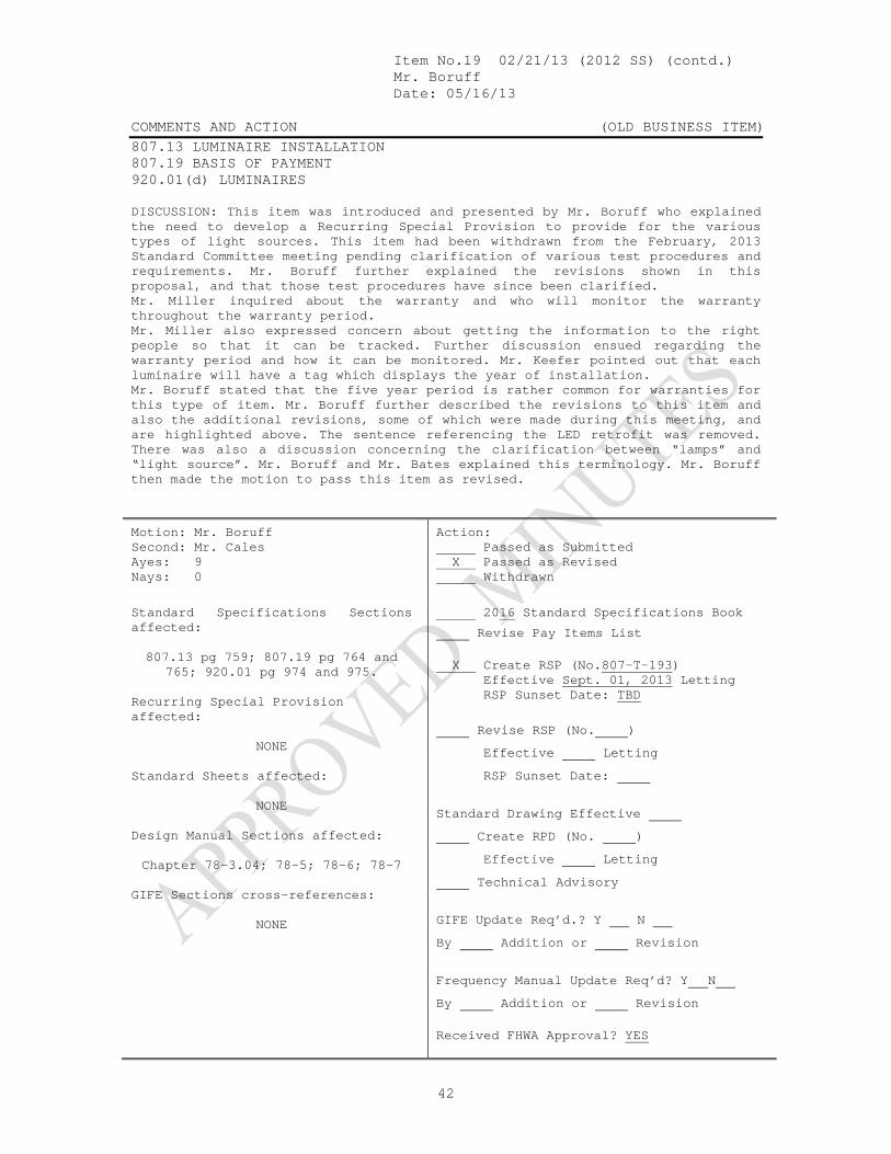
Item No.19 02/21/13 (2012 SS) (contd.) Mr. Boruff Date: 05/16/13 COMMENTS AND ACTION (OLD BUSINESS ITEM) 807.13 LUMINAIRE INSTALLATION 807.19 BASIS OF PAYMENT 920.01(d) LUMINAIRES
42
DISCUSSION: This item was introduced and presented by Mr. Boruff who explained the need to develop a Recurring Special Provision to provide for the various types of light sources. This item had been withdrawn from the February, 2013 Standard Committee meeting pending clarification of various test procedures and requirements. Mr. Boruff further explained the revisions shown in this proposal, and that those test procedures have since been clarified. Mr. Miller inquired about the warranty and who will monitor the warranty throughout the warranty period. Mr. Miller also expressed concern about getting the information to the right people so that it can be tracked. Further discussion ensued regarding the warranty period and how it can be monitored. Mr. Keefer pointed out that each luminaire will have a tag which displays the year of installation. Mr. Boruff stated that the five year period is rather common for warranties for this type of item. Mr. Boruff further described the revisions to this item and also the additional revisions, some of which were made during this meeting, and are highlighted above. The sentence referencing the LED retrofit was removed. There was also a discussion concerning the clarification between “lamps” and “light source”. Mr. Boruff and Mr. Bates explained this terminology. Mr. Boruff then made the motion to pass this item as revised.
Motion: Mr. Boruff Second: Mr. Cales Ayes: 9 Nays: 0
Action: Passed as Submitted X Passed as Revised Withdrawn
Standard Specifications Sections affected:
807.13 pg 759; 807.19 pg 764 and
765; 920.01 pg 974 and 975. Recurring Special Provision affected:
NONE Standard Sheets affected:
NONE Design Manual Sections affected: Chapter 78-3.04; 78-5; 78-6; 78-7
GIFE Sections cross-references:
NONE
2016 Standard Specifications Book
Revise Pay Items List X Create RSP (No.807-T-193) Effective Sept. 01, 2013 Letting RSP Sunset Date: TBD
Revise RSP (No. ) Effective Letting RSP Sunset Date:
Standard Drawing Effective Create RPD (No. ) Effective Letting Technical Advisory
GIFE Update Req’d.? Y N By Addition or Revision
Frequency Manual Update Req’d? Y N By Addition or Revision Received FHWA Approval? YES

Mr. Boruff Date: 05/16/13 SPECIFICATION, SPECIAL PROVISIONS AND DRAWINGS REVISION TO STANDARD SPECIFICATIONS
43
PROPOSAL TO STANDARDS COMMITTEE
PROBLEM(S) ENCOUNTERED: Flagger safety continues to be a concern in construction and maintenance work zones. Automated Flagger Assistance Devices that use STOP/SLOW signs are an option to traditional flagging and they allow the flagger to be positioned off the roadway getting them out of harms way. They have been incorporated into the Indiana Manual on Uniform Traffic Control Devices but INDOT does not have specifications or approved materials list to support their use. PROPOSED SOLUTION: Create a specification that can be used in conjunction with a new Indiana Test Method and an approved materials list. APPLICABLE STANDARD SPECIFICATIONS: 801.02, 801.15; 801.18; 923.06 APPLICABLE STANDARD DRAWINGS: APPLICABLE DESIGN MANUAL SECTION: APPLICABLE SECTION OF GIFE: APPLICABLE RECURRING SPECIAL PROVISIONS: PAY ITEMS AFFECTED: Submitted By: Dave Boruff Title: Manager, Office of Traffic Administration Organization: INDOT Phone Number: 317-234-7975 Date: 04/22/13 APPLICABLE SUB-COMMITTEE ENDORSEMENT: Traffic Standards Subcommittee, Industry.
Item No.01 05/16/13 (2012 SS) (contd.) Mr. Boruff Date: 05/16/13 REVISION TO STANDARD SPECIFICATIONS SECTION 801 – TRAFFIC CONTROLS FOR CONSTRUCTION AND MAITENANCE OPERATIONS 801.02 MATERIALS 801.15 ELECTRONIC DEVICES 801.18 BASIS OF PAYMENT SECTION 923 – TEMPORARY TRAFFIC CONTROL DEVICES
44
The Standard Specifications are revised as follows: SECTION 801, BEGIN LINE 11, INSERT AS FOLLOWS:
801.02 Materials Materials shall be in accordance with the following: Automated Flagger Assistance Devices .................................923.07 Coarse Aggregate, Class D or Higher, Size No. 73 ...............904 Construction Warning Lights .................................................923.03 SECTION 801, AFTER LINE 790, INSERT AS FOLLOWS: (e) Automated Flagger Assistance Devices An Automated Flagger Assistance Device, AFAD, may be used to control a single lane of approaching traffic on a two-lane highway for flagging operations. Only qualified flaggers who have been trained on the operation of the AFAD shall operate the AFAD. AFAD operators shall be able to provide written proof that they have been trained by the AFAD manufacturer. Two trained flaggers shall be available on-site to provide flagging in case of an AFAD malfunction. The flagger operating the AFAD shall be positioned to have unobstructed line of sight to approaching traffic and the AFAD. A single flagger may be used to control both approaches to the work site if adequate, unobstructed sight distance exists between the AFAD operator and both approaching directions of traffic and both AFADs. The flagger operating the AFAD shall not leave the device unattended at any time while the AFAD is in use. The operating flagger shall be positioned at such point to be in full view of oncoming traffic and the AFAD at all times the AFAD is in use. The flagger operator shall keep a back up hand held remote readily available at all times when the device is being operated. The AFAD shall be positioned so that the end of the gate arm, if used, shall extend at least to the center of the lane being controlled but shy of the roadway centerline. A drum shall be placed immediately in front of the AFAD trailer at both corners for delineation. SECTION 801, BEGIN LINE 1137, INSERT AS FOLLOWS: The cost of necessary flaggers; automated flagger assistance devices; protection of traffic at structure foundations; and furnishing, erecting, placing, maintaining, relocating, and removing lights, cones, flexible channelizers, tubular markers, drums,

Item No.01 05/16/13 (2012 SS) (contd.) Mr. Boruff Date: 05/16/13 REVISION TO STANDARD SPECIFICATIONS SECTION 801 – TRAFFIC CONTROLS FOR CONSTRUCTION AND MAITENANCE OPERATIONS 801.02 MATERIALS 801.15 ELECTRONIC DEVICES 801.18 BASIS OF PAYMENT SECTION 923 – TEMPORARY TRAFFIC CONTROL DEVICES
45
delineators, or other devices as directed shall be included in the cost of maintaining traffic. SECTION 923, BEGIN LINE 238, INSERT AS FOLLOWS: 923.07 Automated Flagger Assistance Device The Automated Flagger Assistance Device, AFAD, shall alternately display a STOP sign and a SLOW sign to control traffic while being operated by a hand held remote control. AFADs shall meet the requirements of the Indiana Manual on Uniform Traffic Control Devices, Chapter 6E. Each AFAD shall be equipped with a gate arm and two hand held remote controls. Trailer mounted AFAD’s shall be equipped with a gate arm. Only automated flagger assistance devices from the List of Approved Solar Powered Traffic Control Devices shall be used. Automated flagger assistance devices will be placed and maintained on the list of approved Solar Powered Traffic Control Devices in accordance with the Indiana Test Method ITM 955. (a) Signs The STOP and SLOW signs shall have a minimum width of 30 24 in. with lettering that is at least 10 8 in. in height. The WAIT ON STOP sign shall be visible along the same line of view of the STOP sign face. (b) Supplemental Conspicuity Devices The STOP sign face shall be supplemented by a circular, red stop beacon. The SLOW sign face shall be supplemented by either: a circular, yellow warning beacon, or Type B warning lights with a minimum viewing distance of 1000 ft. (c) Gate Arm Gate arms shall be made of reinforced thermoplastic or tubular aluminum. When in the horizontal positions the arm shall have a 2 ft to 4 ft mounting height above the pavement surface (d) Cabinets and Controller The battery and controller cabinets shall be in accordance with NEMA Standard 250 Enclosure 3R requirements and be provided with a hasp and lock. The AFAD shall include a manual override of the hand held remote at the device. The AFAD shall not have any means by which it can operate on a pre-set or pre-timed basis. (e) Remote Control Device Two hand held, cordless remote controls shall be provided with each AFAD. The remote control shall be waterproof and display signal receipt confirmation. The remote
Item No.01 05/16/13 (2012 SS) (contd.) Mr. Boruff Date: 05/16/13 REVISION TO STANDARD SPECIFICATIONS SECTION 801 – TRAFFIC CONTROLS FOR CONSTRUCTION AND MAITENANCE OPERATIONS 801.02 MATERIALS 801.15 ELECTRONIC DEVICES 801.18 BASIS OF PAYMENT SECTION 923 – TEMPORARY TRAFFIC CONTROL DEVICES
46
shall use a frequency hopping, spread spectrum radio signal with frequencies outside the 700MHz band, 698 MHz to 806 MHz. The remote control device shall be programmable to control either one unit or two units simultaneously and shall control the units over a one-mile range. Remote control batteries shall be rechargeable. A recharging device shall be provided with each remote. (f) Batteries and Charging System Batteries shall be deep cycle type and be capable of operating the AFAD continuously for fourtwo days, 24 hrs per day without a need of re-charging. An audible low battery voltage alarm sound system shall be provided. The battery charging system shall consist of a solar panel. Solar panels shall be UL 1703 certified. (g) Trailer The trailer, if used, shall be designed to withstand a 60 mph wind loading with a 1.3 gust factor when the AFAD is set up in operating position. The trailer shall be painted safety orange, Federal Standard 595, color No. 12300. The trailer shall be provided with a minimum of two leveling jacks, each operated by a crank which locks in place.
Item No.01 05/16/13 (2012 SS) (contd.) Mr. Boruff Date: 05/16/13 COMMENTS AND ACTION 801.02 MATERIALS 801.15 ELECTRONIC DEVICES 801.18 BASIS OF PAYMENT SECTION 923 – TEMPORARY TRAFFIC CONTROL DEVICES
47
DISCUSSION: This item was introduced and presented by Mr. Boruff who explained the need for increased methods concerning flagger safety, and described how these items operate. Mr. Bruno handed out photo examples of these devices being used. Mr. Pankow asked about the ITM 955, and Mr. Walker explained that it is the next number in line and that it has yet to be written, but will contain information so that the Department will be able to perform the testing of the devices. Mr. Pankow also inquired about how to ensure that only qualified and trained personnel will be operating the equipment. Mr. Lee (ICA) explained that there already exists training requirements for flaggers, and that the burden for this training will fall on the Contractor, and that the MUTCD explains the training requirements for flaggers. Mr. Walker asked if we can inquire of the manufacturer to see if they have a training program for this device. Mr. Miller asked if we should have additional information in this spec to define the flagger qualifications for the AFAD. Mr. Pankow and Mr. Lee discussed whether or not there should be a defined maximum distance allowed for use of these devices. Mr. Keefer pointed out that the spec already says that the devices can only be used if the operator can clearly see both ends. The group also discussed having the device requirements shown in the spec as well as in the ITM. The decision was that the information should remain in the spec so our own people have the information readily available to them. There was also much discussion over the wording of the signs. Additionally, the sign size and lettering heights were revised by the committee, as shown. Mr. Boruff also introduced minor editorial revisions to this proposal and moved that this item be passed as revised, pending incorporation of additional flagger certification language. No pay items are affected since this work will be covered under MOT pay items.

Item No.01 05/16/13 (2012 SS) (contd.) Mr. Boruff Date: 05/16/13 COMMENTS AND ACTION 801.02 MATERIALS 801.15 ELECTRONIC DEVICES 801.18 BASIS OF PAYMENT SECTION 923 – TEMPORARY TRAFFIC CONTROL DEVICES
48
(continued)
Motion: Mr. Boruff Second: Mr. Cales Ayes: 8 Nays: 1 (Mr. Pankow)
Action: Passed as Submitted X Passed as Revised Withdrawn
Standard Specifications Sections affected:
801.02 pg 694; 801.15 pg 711; 801.18 pg 718; 923.06 pg 1027.
Recurring Special Provision affected:
NONE Standard Sheets affected:
NONE Design Manual Sections affected:
NONE GIFE Sections cross-references:
NONE
2016 Standard Specifications Book
Revise Pay Items List X Create RSP (No. 801-T-194) Effective Sept.01, 2013 Letting RSP Sunset Date: TBD
Revise RSP (No. ) Effective Letting RSP Sunset Date:
Standard Drawing Effective Create RPD (No. ) Effective Letting Technical Advisory
GIFE Update Req’d.? Y N By Addition or Revision
Frequency Manual Update Req’d? Y N By Addition or Revision Received FHWA Approval? YES

Mr. Boruff Date: 05/16/13 SPECIFICATION, SPECIAL PROVISIONS AND DRAWINGS REVISIONS TO SPECIAL PROVISIONS
49
PROPOSAL TO STANDARDS COMMITTEE
PROBLEM(S) ENCOUNTERED: The changes to the traffic signal specifications approved at the Standards Committee meeting on 02/21/2013 separated several proprietary items from the rest of Section 805. These proprietary items will stay as recurring special provisions. However, it has been observed that the pay items for the magnetometer and microloop detectors RSP, as well as the radio interconnect RSP are missing a few references back to the 805 pay items. PROPOSED SOLUTION: The proposed changes to the approved RSP's will add the 805 pay item references that are needed. APPLICABLE STANDARD SPECIFICATIONS: 805.07, 805.10, 805.15, 805.16, 922.12 APPLICABLE STANDARD DRAWINGS: N/A APPLICABLE DESIGN MANUAL SECTION: 77.402(03) and 77-6.03 APPLICABLE SECTION OF GIFE: N/A APPLICABLE RECURRING SPECIAL PROVISIONS: 805-T-XXX, 805-T-XXX PAY ITEMS AFFECTED: 805-08464 Radio Interconnect, 805-08466 Radio Antenna, 9db Yagi, 805-08493 Radio Interconnection System Testing, 805-09088 Radio Omni Antenna, 805-09089 Radio Yagi Antenna, 805-09091 Radio Dual Yagi Antenna, 805-11540 Microloop Detector Probe, 805-11544 Radio Splitter, 805-11570 Radio Antenna, 805-93611 Magnetometer Detector Submitted By: Dave Boruff Title: Traffic Administration Manager Organization: INDOT Phone Number: (317) 234-7975 Date: 4/22/2013 APPLICABLE SUB-COMMITTEE ENDORSEMENT: Yes, Traffic Standards Subcommittee and the Traffic Control Systems Division.

Item No.02 05/16/13 (2012 SS) (contd.) Mr. Boruff Date: 05/16/13 REVISION TO SPECIAL PROVISIONS 805-X-XXX (# TBD) MAGNETOMETERS AND MICROLOOP DETECTORS
50
(Note: proposed changes shown as highlighted gray. The Standards Committee has approved this RSP on 02/21/2013 meeting with an effective date on or after September 01, 2013 and as an edition to the 2014
Standard Specifications.)
805-X-XXX MAGNETOMETERS AND MICROLOOP DETECTORS
(Adopted xx-xx-xx) Description This work shall consist of furnishing and installing magnetometer or microloop vehicle detection, as specified in the plans. Materials Materials for microloop detectors shall be selected from the Department’s approved materials list. The microloop detectors selected shall be capable of counting vehicles in addition to detecting vehicle presence. Each microloop detector location shall include the following items: 1. Non-invasive probe, lead-in cable and carriers for
microloop detector as shown on the plans; 2. 3-in. diameter schedule 80 HDPE conduit containing the
probes, lead-in cable and carriers; 3. Buried service wire encapsulation kit compatible with
microloop detector for all splicing between the lead-in cable and the home run cable;
4. Installation kit, one for each conduit containing probes; 5. All mounting hardware, conduit bushings, wiring,
connectors, grounding wires, ground rods, grounding cables, etc., necessary to complete the microloop detector location installation.
Testing Before installation of magnetometer or microloop probes the Contractor shall confirm the adequacy of the magnetic field intensity, to be sure that the range is suitable for their operation. The Contractor shall demonstrate that the microloop count data recorded in the controller’s detector log is within 5% of count data obtained visually over a 15-minute period for every detector installation. The test shall be performed by the Contractor in the presence of the Engineer. If detector sensitivity or calibration settings are adjusted in order to meet this test, the new settings shall be recorded on the wiring diagram in the cabinet. Installation Arrangement of probes shall be located at maximum distance from metal objects as per manufacturer’s recommendation. Probes shall be

Item No.02 05/16/13 (2012 SS) (contd.) Mr. Boruff Date: 05/16/13 REVISION TO SPECIAL PROVISIONS 805-X-XXX (# TBD) MAGNETOMETERS AND MICROLOOP DETECTORS
51
installed with their long dimension vertical, and with the cable end at the top. Probes shall be firmly supported, so the lateral and vertical motion is restricted. Probes shall be connected in series. The splice shall be soldered by means of hot iron, or pouring or dripping without flames, with rosin core solder and shall be insulated and waterproofed in accordance with the manufacturer’s specifications. Conduit for the microloop detector probes shall be directionally pushed beneath the pavement at the depth and slope determined by the manufacturer to ensure proper carrier and probe installation. The Contractor shall repair any damage to the pavement that occurs during the installation. The microloop detector probe location in each lane shall be per the manufacturer’s recommendation. Method of Measurement Magnetometer detector and microloop detector probe will be measured by the number of units installed. Conduit and signal cable will be measured in accordance with 805.15. Basis of Payment If specified as pay items, magnetometer detector and microloop detector probe will be paid for at the contract unit price per each.
Conduit and signal cable will be paid for in accordance with 805.16. Payment will be made under: Pay Item Pay Unit Symbol Magnetometer Detector ........................................EACH Microloop Detector Probe .....................................EACH The cost of coring the pavement, sealant, and all work necessary for proper installation and operation of the in-pavement sensors shall be included in the cost of magnetometer detector. The cost of the detector unit, lead-in cable, and all work necessary for proper installation shall be included in the cost of magnetometer detector or microloop detector probe. The cost of all hardware and work required to provide and install signal cable from microloop detector probe, including extra-low voltage (home-run), from the handhole adjacent to the detector probe to the controller cabinet shall be included in the cost of signal cable.

Item No.02 05/16/13 (2012 SS) (contd.) Mr. Boruff Date: 05/16/13 REVISION TO SPECIAL PROVISIONS 805-X-XXX (# TBD) RADIO INTERCONNECTION
52
(Note: proposed changes shown as highlighted gray. The Standards Committee has approved this RSP on 02/21/2013 meeting with an effective date on or after September 01, 2013 and as an edition to the 2014
Standard Specifications.)
805-X-XXX RADIO INTERCONNECTION
(Adopted xx-xx-xx) Description This work shall consist of furnishing and installing spread spectrum radio equipment for interconnecting traffic signal controllers at signalized intersections. Materials The Contractor shall select radio equipment materials from the Department’s list of approved Traffic Signal and ITS Control Equipment. The Contractor shall furnish 2 copies of the instructions for hardware installation, programming and system commissioning. The spread spectrum radio modems shall provide all the needed features to communicate with NEMA TS2 type 1 and type 2 traffic signal controllers in a coordinated closed loop system. Radio modems shall be capable of both Ethernet and serial data transfer. The radio modems shall be software configurable to be either a master, repeater, repeater/slave, or slave radio. The radio modem shall require no user license from the FCC; operate in the 900 MHz range, and be of frequency hopping spread spectrum, FHSS, technology; support data rates from 1.2 kbps to 115.2 kbps asynchronous; have a receiver sensitivity of at least -110 dBm; have a minimum RF output level of 1 watt; have a minimum of 50 user-selectable hopping patterns and a minimum of 50 RF non-overlapping channels allowing multiple systems to operate in the same line-of-sight path; operate as a transparent RS232, or RS422/RS485, or FSK 1200 baud types of links for use in a point-to-multipoint system; provide an RJ-45 10/100BaseT Ethernet interface; be IP addressable; have an external SMA female type or N-female RP-TNC female antenna connector; and be supplied with power supply for 120V AC operation. The modems shall be rack or shelf mounted in standard NEMA TS2 type 1 or type 2 cabinets. The modems shall have an operation temperature of -40 to 176°F, have a maximum current draw of 500 mA for the transmission of 1 watt of RF output power, while operating on 12V DC. Lighting and transient protection on all data lines and antenna connector, and AC/DC power distribution, shall be provided with the system. The spread spectrum radio modems must include a Windows based, configuration software package, which will include a graphical user interface, GUI, allowing for ease of programming, through pre-written drivers for all Department approved traffic controllers and have the ability to automatically determine, and connect, at their radios baud, stop and parity settings. The configuration software must allow for signal level, RSSI, data integrity, message polling, and spectral analysis testing. The software must also permit all the radios within a system to be configured from a single location. All radio equipment and cables shall be delivered preconfigured and ready for field operation.

Item No.02 05/16/13 (2012 SS) (contd.) Mr. Boruff Date: 05/16/13 REVISION TO SPECIAL PROVISIONS 805-X-XXX (# TBD) RADIO INTERCONNECTION
53
The manufacturer, or vendor, shall supply with each modem, the operational manual containing procedures for all features incorporated in the modem. a. Transient Protection Transient protection shall be installed between the radio modem and the field antenna. The transient protection shall be flange mounted in the cabinet and have a minimum transient current of 40 kA for 8 x 20 μs pulse, an insertion loss or < 0.1 dB, have an operating frequency in the 900 MHz range, allow throughput energy to be < 220 μJ for 6 kV /3 kA @ 8/20 μs waveform, have throughput voltage≤ 144 Vpk, and turn –on voltage shall be ± 600 volts. The unit impedance shall be 50 Ω. b. Antennas The antenna for the radio modem at the system master/local controllers shall be capable of providing a transmission range adequate for communication with all radio modems or repeaters in the system and must be configured as a single omni, single-yagi, or dual-yagi (2 single-yagi antennas on differing alignments) for each radio as described below. (1) Omni Antennas All omni antennas shall be capable of producing between 6 dBd and 10 dBd (8.15 dBi and 12.15 dBi) of gain while operating in, and covering the entire 902-930 MHz frequency range. The voltage standing wave ratio, VSWR, of the omni antenna shall be 1.5:1 or less when the antenna coax feed impedance is 50 Ω. Omni antennas shall be fabricated of fiberglass, brass, copper, and/or aluminum and shall be rated for wind velocities of at least 100 mph. The minimum length of the omni antenna shall be 60 in. and it shall be designed and fabricated with a fiberglass radome with a minimum diameter of 2 in. to prevent ice from collecting directly on the driven element. All omni antennas shall have a cableless N-female connector directly affixed and sealed to the antenna body. All hardware and fastenings devices shall be fabricated from stainless steel. (2) Yagi / Dual-Yagi Antennas All yagi antennas shall be capable of producing between 10 dBd and 13 dBd (12.15 dBi and 15.15 dBi) of gain while operating in, and covering the entire 902-930 MHz frequency range. The voltage standing wave ratio,VSWR, of the omni antenna shall be 1.5:1 or less when the antenna coax feed impedance is 50 Ω. The front to back ratio must be at least 20 dB for each yagi antenna. Yagi-directional antennas shall be fabricated of either anodized or powder coated 6061/T6 aluminum rod and seamless drawn pipe and shall be rated for wind velocities of at least 100 mph. All yagi antennas shall have a cableless N-female connector directly affixed and sealed to the antenna body. The yagi antenna shall be designed and fabricated so that polarization changes (vertical to horizontal) can be made on the antenna mount without adjusting the mast. Single yagis shall be connected by a low loss N-female “T” splitter/coupler and LMR-400 cable to form dual-yagi systems. All hardware and fastenings devices shall be fabricated from stainless steel.

Item No.02 05/16/13 (2012 SS) (contd.) Mr. Boruff Date: 05/16/13 REVISION TO SPECIAL PROVISIONS 805-X-XXX (# TBD) RADIO INTERCONNECTION
54
c. Antennas Cable and Hardware The coaxial cable used as the transient protection to antenna lead shall have no greater than 3.8 dB loss per 100 ft of length and shall be LMR-400. All LMR-400 connections are to be stripped, deburred, and crimped using the ST-400-EZ LMR-400 stripping tool, DBT-01 LMR-400 deburring tool, and a 0.429 in. hex crimp die for solderless LMR-400 connections respectively. All connections shall be completely sealed by heat shrinking double walled, adhesive lined shrink tubing for weather proofing and strain relief. Cables shall be included to interface the radio equipment to the transient protection. The antenna mounting hardware shall securely attach the antenna to the strain pole/cantilever arm. The coaxial cable fitting on the antenna shall not support the weight of the coaxial cable run to the base of the strain pole/cantilever arm. d. Data Cables Cables shall be included to interface the radio equipment to the system master, co-located secondary controller, remote secondary controllers and any communication interface panels as needed. Cables shall include strain relief back shells designed to mate and lock with the telemetry connector on the system master and local controllers. All radio equipment and cables shall be delivered preconfigured and ready for field operation. All miscellaneous equipment necessary to complete the installation shall be as specified by the radio modem manufacturer. Construction Requirements To receive maximum signal strength, the radio antennas shall be positioned by adjusting the antenna direction while monitoring signal strength through the telemetry radio. The radio antenna mounts shall be securely fastened to the poles. Coaxial cable shall be installed inside metal poles and conduits. External cable on poles shall not exceed 3 ft unless approved by the Engineer. Approved external cable runs exceeding 3 ft shall be secured using manufacturer specified hangers at a maximum spacing of 3 ft. Cable terminations shall be in accordance with the manufacturer’s recommendations. Connectors outside of cabinets shall be sealed in accordance with the manufacturer’s recommendations. The Contractor shall deburr any holes made in metal poles and install grommets for protection. Drip loops shall be provided between the antenna connector and the metal pole entrance or first pole clamp. Cable bends shall be in accordance with the manufacturer’s specified bending radius. Testing Test of the radio interconnection system shall be performed after the installation is complete. Notice of the testing shall be provided to the district traffic office at least 2 work days prior to the test. The Contractor shall adjust the radio antennas to optimize the communication signal for the system. The strength of the communication signal shall be determined using computer software provided by the radio interconnection system manufacturer. The test shall be conducted

Item No.02 05/16/13 (2012 SS) (contd.) Mr. Boruff Date: 05/16/13 REVISION TO SPECIAL PROVISIONS 805-X-XXX (# TBD) RADIO INTERCONNECTION
55
with complete foliage on deciduous trees in the vicinity or on a date approved by the Engineer. The test results shall include the signal strength, site polling results using long message polling, and noise levels. The test results shall be above the minimum guidelines set by the radio interconnect system manufacturer. Method of Measurement Radio antenna; radio interconnect; radio splitter; will be measured by the number of units installed
Signal cable will be measured in accordance with 805.15. Radio, interconnection system testing will not be measured for payment. Basis of Payment Radio, interconnection system testing will be paid for at the contract lump sum price. Signal cable will be paid for in accordance with 805.16. If specified as pay items, radio antenna; radio interconnect; radio splitter; will be paid for at the contract unit price per each.
Payment will be made under: Pay Item Pay Unit Symbol Radio Antenna ....................................... EACH Radio, Interconnect .................................. EACH Radio, Interconnection System Testing ......................... LS Radio Splitter .............................................. EACH The cost of the radio modem and all component parts, except an antenna or splitter, necessary to interconnect a traffic signal to one or more signalized intersections shall be included in the cost of Radio, Interconnect.
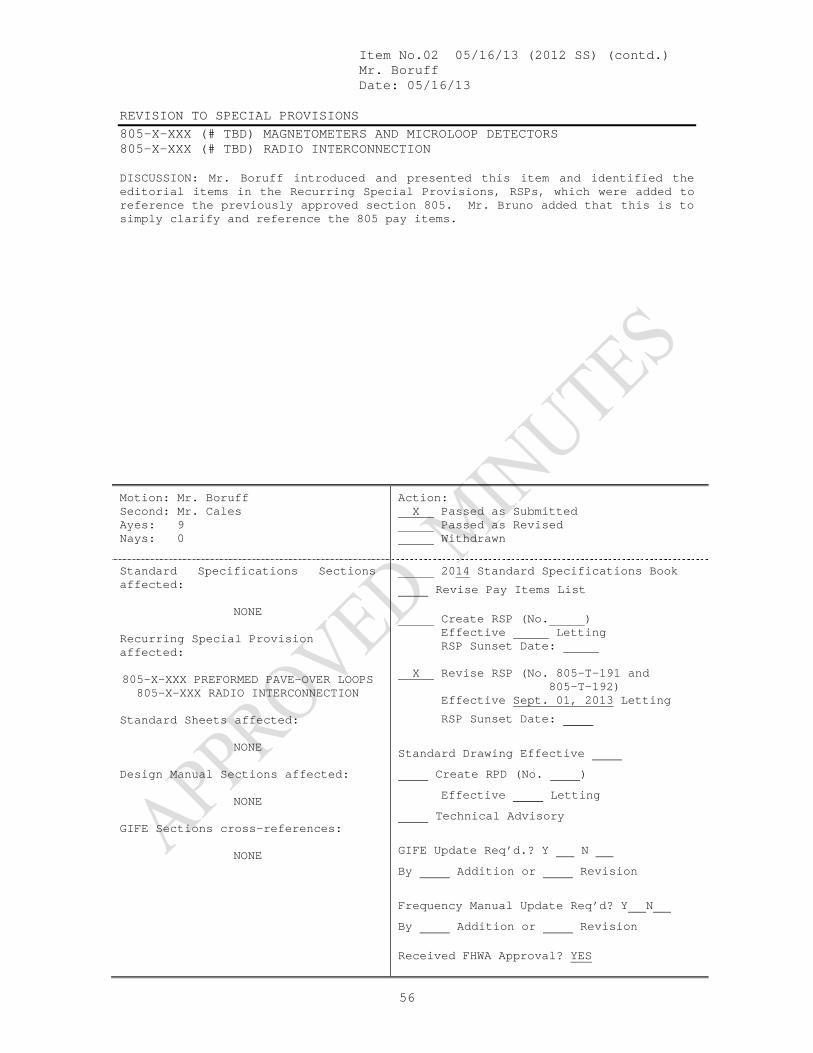
Item No.02 05/16/13 (2012 SS) (contd.) Mr. Boruff Date: 05/16/13 REVISION TO SPECIAL PROVISIONS 805-X-XXX (# TBD) MAGNETOMETERS AND MICROLOOP DETECTORS 805-X-XXX (# TBD) RADIO INTERCONNECTION
56
DISCUSSION: Mr. Boruff introduced and presented this item and identified the editorial items in the Recurring Special Provisions, RSPs, which were added to reference the previously approved section 805. Mr. Bruno added that this is to simply clarify and reference the 805 pay items.
Motion: Mr. Boruff Second: Mr. Cales Ayes: 9 Nays: 0
Action: X Passed as Submitted Passed as Revised Withdrawn
Standard Specifications Sections affected:
NONE
Recurring Special Provision affected: 805-X-XXX PREFORMED PAVE-OVER LOOPS
805-X-XXX RADIO INTERCONNECTION Standard Sheets affected:
NONE Design Manual Sections affected:
NONE GIFE Sections cross-references:
NONE
2014 Standard Specifications Book
Revise Pay Items List Create RSP (No. ) Effective Letting RSP Sunset Date: X Revise RSP (No. 805-T-191 and 805-T-192) Effective Sept. 01, 2013 Letting
RSP Sunset Date:
Standard Drawing Effective Create RPD (No. ) Effective Letting Technical Advisory
GIFE Update Req’d.? Y N By Addition or Revision
Frequency Manual Update Req’d? Y N By Addition or Revision Received FHWA Approval? YES

Mr. Boruff Date: 05/16/13
SPECIFICATION, SPECIAL PROVISIONS AND DRAWINGS REVISION TO SPECIAL PROVISION AND STANDARD DRAWINGS
57
PROPOSAL TO STANDARDS COMMITTEE
PROBLEM(S) ENCOUNTERED: The JTRP study Alternatives to Raised Pavement Markers (SPR-3528) has identified several advantages to the use of longitudinal rumble stripes, which are a combination of milled corrugations and centerline or edgeline pavement markings placed in the corrugations. Longitudinal rumble stripes are used in many other states and improves the durability and retroreflectivity of the pavement markings and the practice has also been shown to significantly reduce roadway departure and centerline crossing crashes. PROPOSED SOLUTION: The proposed specifications and standard drawings will describe and show the proper construction methods for longitudinal rumble stripes. The specs, drawings, and designer guidance represent the best practices in other states and from the test projects under the JTRP study. APPLICABLE STANDARD SPECIFICATIONS: 401.17, 402.17, 501.24, 606, 808.04 APPLICABLE STANDARD DRAWINGS: APPLICABLE DESIGN MANUAL SECTION: 76-3.02 APPLICABLE SECTION OF GIFE: N/A APPLICABLE RECURRING SPECIAL PROVISIONS: 606-R-563, 606-R-563d PAY ITEMS AFFECTED: 606-09729 Milled Centerline Corrugations 402-05484 HMA Rumble Strips Submitted By: Dave Boruff Title: Traffic Administration Manager Organization: INDOT Phone Number: (317) 234-7975 Date: 4/22/2013 APPLICABLE SUB-COMMITTEE ENDORSEMENT: Yes, Traffic Standards Subcommittee, the SAC for SPR-3528, and the INDOT Office of Traffic Safety.
Item No.03 05/16/13 (2012 SS) (contd.) Mr. Boruff Date: 05/16/13 REVISION TO SPECIAL PROVISIONS AND STANDARD DRAWINGS PROPOSED NEW XXX-X-XXX LONGITUDINAL RUMBLE STRIPES
58
XXX-X-XXX LONGITUDINAL RUMBLE STRIPES
(Adopted xx-xx-13)
The Standard Specifications are revised as follows: SECTION 401, BEGIN LINE 434, INSERT AS FOLLOWS: 401.17 Shoulder, Center Line, and Edge LinePavement Corrugations Shoulder, center line, and edge linePavement corrugations shall be in accordance with 606. SECTION 401, BEGIN LINE TBD, INSERT AS FOLLOWS: The cost of the liquid asphalt sealant for the joint adhesive and, centerline or edge line corrugations shall be included in the cost of the joint adhesive. SECTION 402, BEGIN LINE 3, INSERT AS FOLLOWS: 402.01 Description This work shall consist of 1 or more courses of HMA base, intermediate, or surface mixtures, and miscellaneous courses for transverse rumble strips, and wedge and leveling constructed on prepared foundations in accordance with 105.03. SECTION 402, BEGIN LINE 78, DELETE AND INSERT AS FOLLOWS: 402.07 Mix Criteria (a) Composition Limits for HMA Transverse Rumble Strip Mixtures Transverse Rumble rumble strip mixtures shall be type A surface in accordance with 402.04. A MAF in accordance with 402.05 will not apply. Aggregate requirements of 904.03(d) do not apply. SECTION 402, BEGIN LINE 271, DELETE AND INSERT AS FOLLOWS: Transverse Rumble rumble strips shall be placed to ensure uniformity of depth, width, texture, and the required spacing between strips. SECTION 402, BEGIN LINE 337, DELETE AND INSERT AS FOLLOWS: Transverse Rumble rumble strips shall be compacted with vibratory compacting equipment in accordance with 409.03(d)6 unless otherwise stated. SECTION 402, BEGIN LINE 421, DELETE AND INSERT AS FOLLOWS:
HMA Transverse Rumble Strips ......................................... LFT (m) SECTION 402, BEGIN LINE 388, INSERT AS FOLLOWS: 402.17 Shoulder, Center Line, and Edge LinePavement Corrugations Shoulder, center line, and edge linePavement corrugations shall be in accordance with 606. SECTION 501, BEGIN LINE 365, INSERT AS FOLLOWS:

Item No.03 05/16/13 (2012 SS) (contd.) Mr. Boruff Date: 05/16/13 REVISION TO SPECIAL PROVISIONS AND STANDARD DRAWINGS PROPOSED NEW XXX-X-XXX LONGITUDINAL RUMBLE STRIPES
59
501.24 Shoulder, Center Line, and Edge LinePavement Corrugations Shoulder, center line, and edge linePavement corrugations shall be in accordance with 606. SECTION 502, BEGIN LINE 362, INSERT AS FOLLOWS: 502.19 Shoulder Pavement Corrugations Shoulder, Pavement corrugations shall be in accordance with 606. SECTION 606, BEGIN LINE 1, DELETE AND INSERT AS FOLLOWS:
SECTION 606 –SHOULDER, CENTER LINE, AND EDGE LINE PAVEMENT CORRUGATIONS
606.01 Description (a) All Corrugations This work shall consist of placing corrugations in the paved shoulders pavement in accordance with 105.03. Corrugations shall not be constructed within the limits of reinforced concrete bridge approaches or in bridge decks. The operation shall be coordinated such that milled materials do not encroach on the pavement lanes carrying traffic and all milled materials are disposed of in accordance with 104.07. When corrugations are installed for center line and edge line rumble stripes, milled materials shall be swept and vacuumed following the milling operation. The corrugation shall be constructed by cutting smooth strips in existing or newly constructed shoulders pavement. The operation shall be conducted by means of a cutting machine that provides a series of smooth cuts without tearing or snagging. The equipment shall include guides to maintain uniformity and consistency in the alignment of the strips. Longitudinal rumble stripes are the combination of either the center line pavement marking placed in the center line corrugation or the edge line pavement marking placed in the edge line corrugation. They shall be installed as shown in the plans and as specified herein. (b) Center Line and Edge Line Corrugations When corrugations are installed for center line and edge line rumble strips control points that are required as a guide for milling corrugations shall be spotted with paint for the full length of the road to be milled. Control points along tangent sections shall be spaced at a maximum interval of 100 ft. Control points along curve sections shall be spaced to ensure the accurate location of the milled corrugations. The location of control points shall be approved prior to the milling operations. If snowplowable raised pavement markers exist in where center line corrugations are being placed into the existing surface, the prismatic reflectors in these markers shall be removed and corrugations gapped a maximum of 60 in. and not within 6 in. of the markers.
Item No.03 05/16/13 (2012 SS) (contd.) Mr. Boruff Date: 05/16/13 REVISION TO SPECIAL PROVISIONS AND STANDARD DRAWINGS PROPOSED NEW XXX-X-XXX LONGITUDINAL RUMBLE STRIPES
60
In the presence of D-1 pavement joints or castings which conflict with the location of the corrugations, the corrugations shall be gapped a maximum of 5 ft and not within 6 in. of the joint or casting. Corrugations installed in asphalt pavements and within or adjacent to a longitudinal joint within the HMA traveled way and on HMA shoulder contiguous with a HMA traveled way or a HMA auxiliary lane shall be sealed using liquid asphalt sealant in accordance with 401.15412.401.15 (note: in 2014 book SECTION 412 – FOG SEAL) 1. Performance Requirements Installation Tolerances Lateral deviation of milled center line or edge line corrugations shall not exceed 1 in. in 100 ft. The alignment of all pavement markings placed within rumble stripes shall be ± 1/2 in. of its specified location. 2. Maintenance of Traffic The rumble stripe traffic control procedures shall be submitted to the Engineer and shall be in accordance with 808.08. Vehicles used in performing the milling, sweeper, vacuum or sealing operations shall have a rear escort vehicle that follows at a distance of 100 to 500 ft. 606.02 Method of Measurement HMA and PCCP shoulder pavement corrugations will be measured by the linear foot, measured parallel to the center line of the roadway. Gaps in PCCP shoulder pavement corrugations at the D-1 joints will be included in the milled PCCP corrugations. Gaps in pavement corrugations for castings will be included in the milled corrugations. 606.03 Basis of Payment HMA and PCCP shoulderpavement corrugations will be paid for at the contract unit price per linear foot, when specified. Payment will be made under: Pay Item Pay Unit Symbol Milled HMA Center Line Corrugations ........................................................ LFT Milled PCCP Center Line Corrugations ....................................................... LFT Milled HMA Edge Line Corrugations ........................................................... LFT Milled PCCP Edge Line Corrugations ......................................................... LFT Milled HMA Shoulder Corrugations ..................................................... LFT (m) Milled PCCP Shoulder Corrugations ..................................................... LFT (m) The cost of removal of existing prismatic reflectors in rumble strip retrofit sections shall be included in the cost of the pay items.

Item No.03 05/16/13 (2012 SS) (contd.) Mr. Boruff Date: 05/16/13 REVISION TO SPECIAL PROVISIONS AND STANDARD DRAWINGS PROPOSED NEW XXX-X-XXX LONGITUDINAL RUMBLE STRIPES
61
Milling, sweeping, vacuum cleaning, operation protection and maintenance of traffic associated with these pay items and all necessary incidentals shall be included in the cost of the pay items. Where corrugations are placed in an existing HMA surface, Lliquid asphalt sealant shall be included in the cost of the pay items. SECTION 808, BEGIN LINE 53, INSERT AS FOLLOWS: 808.04 Longitudinal Markings All longitudinal lines shall be clearly and sharply delineated, straight and true on tangent, and form a smooth curve where required. Lines shall be square at both ends, without mist, drip or spatter. A solid line shall be continuous. A broken line shall consist of 10 ft line segments with 30 ft gaps. All lines shall be gapped at intersections unless otherwise specified or directed. The actual repainting limits for no-passing zone markings will be determined by the Engineer. A new broken line placed over an existing broken line shall laterally match the existing broken line, and the new line segments shall not extend longitudinally more than 10% beyond either end of the existing line segments. (a) Center Lines Center lines shall be used to separate lanes of traffic moving in opposite directions. All center line markings shall be yellow in color and 4 in. in width. They shall be placed such that the edge of the marking, nearest to the geometric centerline of the roadway, shall be offset 4 in. from the geometric centerline. The center line of a multi-lane roadway shall be marked with a double solid line. The 2 lines forming the double solid line shall be spaced 8 in. apart and shall be equally offset on opposite sides of the geometric centerline. The center line of a 2-lane, 2-way roadway, where passing is allowed in both directions, shall be marked with a broken line. The center line of a 2-lane, 2-way roadway, where passing is allowed in 1 direction only, shall be marked with a double line, consisting of a broken line and a solid line. The broken line and the solid line shall be spaced 8 in. apart and shall be equally offset on opposite sides of the geometric centerline. The solid line shall be offset toward the lane where passing is prohibited. The broken line shall be offset toward the lane where passing is permitted.

Item No.03 05/16/13 (2012 SS) (contd.) Mr. Boruff Date: 05/16/13 REVISION TO SPECIAL PROVISIONS AND STANDARD DRAWINGS PROPOSED NEW XXX-X-XXX LONGITUDINAL RUMBLE STRIPES
62
The center line shall be placed within the milled corrugation when center line rumble stripes are specified. Placement of the center line marking in the rumble stripmilled corrugation does not alter the pavement marking performance requirements of section 808.07. (b) Lane Lines Lane lines shall be used to separate lanes of traffic moving in the same direction. Normal lane line markings shall be white in color and shall be 5 in. wide on freeways, interstates and toll roads, and 4 in. wide on all other roads. They shall be offset 4 in. to the right of longitudinal pavement joints or divisions between traffic lanes. Normal lane lines shall be marked with white broken lines. White solid lines shall be used to mark lane lines only when specified or directed. (c) Edge Lines Edge lines shall be used to outline and separate the edge of pavement from the shoulder. Edge line markings shall be 4 in. in width and shall be placed such that the edge of the marking nearest the edge of the pavement shall be offset 4 in. from the edge of the pavement except as otherwise directed. Right edge lines shall be marked with a white solid line and left edge lines shall be marked with a yellow solid line. The edge line shall be placed in the milled corrugation when edge line rumble stripes are specified. Placement of the edge line marking in the milled corrugation does not alter the pavement marking performance requirements of section 808.07. (d) Barrier Lines Barrier lines shall be used as specified or directed. Barrier line markings shall be solid lines of the size and color specified or as directed. (e) Markings in Retrofitted Corrugations In sections where corrugations are being placed in the existing surface all existing pavement markings shall be removed in accordance with 808.10 and any existing sealants shall be routed or grinded out. Temporary pavement markings placed in accordance with 801.12 shall be offset a sufficient distance from the longitudinal joint so as to not to obstruct the installation of the corrugations or the application of the liquid asphalt sealant. The Contractor shall make a record of the existing pavement marking locations so that such markings may be replicated later with the appropriate adjustments for edge line rumble stripes. This record shall show longitudinal and transverse dimensions. The record shall be submitted to and approved by the District Traffic Engineer prior to the removal of existing pavement markings. The District Traffic Section shall be notified two weeks prior to applying pavement markings so as to allow the District Traffic Section to verify the pavement marking plan.
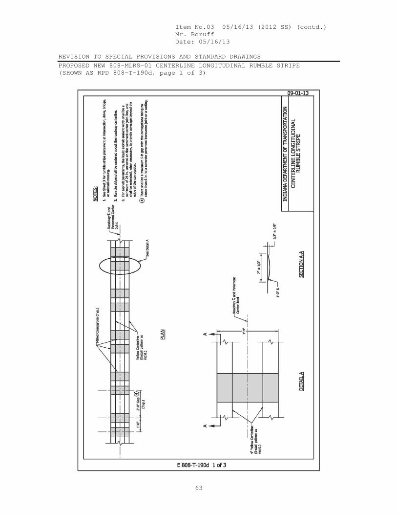
Item No.03 05/16/13 (2012 SS) (contd.) Mr. Boruff Date: 05/16/13 REVISION TO SPECIAL PROVISIONS AND STANDARD DRAWINGS PROPOSED NEW 808-MLRS-01 CENTERLINE LONGITUDINAL RUMBLE STRIPE (SHOWN AS RPD 808-T-190d, page 1 of 3)
63

Item No.03 05/16/13 (2012 SS) (contd.) Mr. Boruff Date: 05/16/13 REVISION TO SPECIAL PROVISIONS AND STANDARD DRAWINGS PROPOSED NEW 808-MLRS-02 EDGELINE LONGITUDINAL RUMBLE STRIPE (SHOWN AS RPD 808-T-190d, page 2 of 3)
64

Item No.03 05/16/13 (2012 SS) (contd.) Mr. Boruff Date: 05/16/13 REVISION TO SPECIAL PROVISIONS AND STANDARD DRAWINGS PROPOSED NEW 808-MLRS-03 LONGITUDINAL RUMBLE STRIPES AT INTERSECTION, DRIVE, OR RAILROAD CROSSING (SHOWN AS RPD 808-T-190d, page 3 of 3)
65

Item No.03 05/16/13 (2012 SS) (contd.) Mr. Boruff Date: 05/16/13 REVISION TO SPECIAL PROVISIONS AND STANDARD DRAWINGS EXISTING RSP 606-R-563 MILLED CENTERLINE CORRUGATIONS (PROPOSED TO DELETE)
66

Item No.03 05/16/13 (2012 SS) (contd.) Mr. Boruff Date: 05/16/13 REVISION TO SPECIAL PROVISIONS AND STANDARD DRAWINGS EXISTING RPD 606-R-563d MILLED CENTERLINE CORRUGATIONS (PROPOSED TO DELETE)
67

Item No.03 05/16/13 (2012 SS) (contd.) Mr. Boruff Date: 05/16/13 REVISION TO SPECIAL PROVISIONS AND STANDARD DRAWINGS EXISTING RPD 606-R-563d MILLED CENTERLINE CORRUGATIONS (PROPOSED TO DELETE)
68
Item No.03 05/16/13 (2012 SS) (contd.) Mr. Boruff Date: 05/16/13 REVISION TO SPECIAL PROVISIONS AND STANDARD DRAWINGS BACKUP 01. DESIGN MEMORANDUM No. XX (DRAFT)
69
INDIANA DEPARTMENT OF TRANSPORTATION Driving Indiana’s Economic Growth Design Memorandum No. xx-__ Technical Advisory
May 17, 2013
DESIGN MEMORANDUM No. xx-__ TECHNICAL ADVISORY TO: All Design, Operations, and District Personnel, and Consultants FROM: _______________________ David Boruff Manager, Office of Traffic Administration Traffic Engineering Division SUBJECT: Center Line and Edge Line Rumble Stripes REVISE: Indiana Design Manual Sections 76-3.01, 76-3.02(05) & 76-3.02(06) EFFECTIVE: To Be Determined INDOT has been using Raised Pavement Markers (RPMs) to provide additional delineation and guidance to drivers on the correct travel path. Based on on-going problems related to maintaining RPMs research has been conducted on using rumble stripes as an alternative. The research results show that the milled corrugation and longitudinal pavement marking combination, known as rumble stripes, will provide better delineation at nighttime and during inclement weather as well as reducing our maintenance efforts. Rumble Stripes should be considered for all projects on two lane rural highways with posted speed limits equal to or greater than 50 mph that include a new pavement surface
Item No.03 05/16/13 (2012 SS) (contd.) Mr. Boruff Date: 05/16/13 REVISION TO SPECIAL PROVISIONS AND STANDARD DRAWINGS BACKUP 01. DESIGN MEMORANDUM No. XX (DRAFT)
70
regardless of pavement type with the exceptions noted herein. Rumble stripes can be considered for projects on two lane rural highways with posted speeds less than 50 mph as safety conditions indicate. Additionally Rumble Stripes may be installed on multilane rural highways or retrofitted on existing pavement when deemed needed by either the District Traffic or Traffic Safety Offices. Therefore, the subject Indiana Design Manual sections have been revised accordingly. Please note that there are criteria for three application scenarios 1) Center and Edge Line, 2) Center Line only, and 3) Edge Line only. Also please note that section 808 of the INDOT Standard Specifications is revised by a recurring special provision to provide additional requirements for longitudinal rumble stripes and their proper installation. For projects where edge line rumbles stripes are included use of Section 606 of the Standard Specifications and the associated pay items will be replaced by the specification and items identified herein. The Pay Item 606-09729 “MILLED CENTERLINE CORRUGATIONS LFT” will be discontinued 76-3.01 Material Types [Rev. Sept. 2011] The pavement marking materials used by INDOT are described below. 1 Paint. Quick-drying paints are applied as a 4-in. or wider white or yellow stripe.
Glass beads are dropped onto the wet paint which then bond to the paint surface when it dries. The use of glass beads greatly enhances the reflectivity of the paint stripe. Per unit cost, paint-applied markings are significantly cheaper than another method. One of the major disadvantages of paint is that it can be quickly worn away on a high-traffic-volume roadway, and, therefore, often needs to be reapplied more than once a year.
2. Thermoplastic. Thermoplastic markings are made from hydrocarbon or alkyd
resins, pigment, and filler. The materials are heated to a high temperature and are applied in thicknesses of 0.1 in. to 0.2 in. The material is applied to the surface and, while it is still hot, glass beads are dropped onto the mixture. Once the material cools, the glass beads are then bonded to the surface. Thermoplastic markings must be applied to a clean, dry asphalt pavement. A primer may be required to ensure satisfactory performance. Thermoplastic markings are significantly more expensive than paint, but often can last 5 or more years if applied properly. Thermoplastic is the preferred marking for a high-traffic-volume roadway due to its long life. 76-2.01(03) Materials and Application. Unless

Item No.03 05/16/13 (2012 SS) (contd.) Mr. Boruff Date: 05/16/13 REVISION TO SPECIAL PROVISIONS AND STANDARD DRAWINGS BACKUP 01. DESIGN MEMORANDUM No. XX (DRAFT)
71
directed by the district Traffic Engineer, thermoplastic should not be specified with longitudinal rumple stripes.
76-3.02(05) Raised Pavement Markers (RPMs) Snowplowable RPMs provide a supplemental method of delineation and are a positive position guidance device. They should not be used as a replacement for standard pavement markings or conventional roadside delineation. The INDOT Standard Drawings provide details on the placement and color locations for RPMs. In addition, the following placement considerations should be reviewed. 1. Location. Site selection should be based primarily on the need for additional
alignment delineation specifically in an area of frequently inclement weather (e.g., fog, smoke, rain) and in an area of low roadway illumination. RPMs placement should be considered where vehicles are leaving the roadway, an area showing excessive wear of existing pavement markings, an area with excessive skid marks, interchange ramp, etc. RPM’s may be considered for urban highways, rural multilane highways, and rural two lane highways that do not meet the criteria for rumble stripes in Section 76-3.02(06).
2. Pavement Life. RPMs should not be placed at a location that is scheduled for
resurfacing or reconstruction within the next four years. 3. Illumination. RPMs may not be required at a location that is illuminated. 4. Traffic Volume. RPMs should be considered where ADT exceeds 2500 for a 2-
lane roadway, or 6000 for a 4-lane roadway. On a lower-volume road, an engineering investigation should be conducted to determine whether RPMs are appropriate to supplement the standard traffic-control devices.
5. Spacing. The spacing for RPMs on a tangent section is 80 ft. Spacing for center
line RPMs used in conjunction with a no-passing zone may be reduced to 40 ft. Six RPMs at 40-ft spacing (240 ft) may be used in advance of and following a delineated no-passing zone. Consideration should be given to connecting two locations or zones of RPMs where the distance between them is less than 3000 ft. See the INDOT Standard Drawings for additional details for spacing at other locations.
6. Special Locations. RPMs should not be used exclusively with edge lines or gore
markings. RPMs may be used at a pavement transition, 1-way or narrow bridge, special channelization area, or where there is strong justification for installation of the devices.
7. Blue Retroreflectors. An RPM with blue retroreflectors should be specified where
a fire hydrant is located within the roadway’s right of way. Such an RPM should
Item No.03 05/16/13 (2012 SS) (contd.) Mr. Boruff Date: 05/16/13 REVISION TO SPECIAL PROVISIONS AND STANDARD DRAWINGS BACKUP 01. DESIGN MEMORANDUM No. XX (DRAFT)
72
be specified only for a roadway where RPMs with yellow or white retroreflectors are to be installed.
The RPM should be placed at an approximately right angle to the fire-hydrant location. It should be a two-way marker visible in both directions of travel. It should be placed in addition to RPMs with yellow or white retroreflectors. For a two-lane, two-way roadway, the RPM should be placed within the transverse limits of the center-line marking. For a 3-lane roadway with a bidirectional left-turn lane, the RPM should be placed within the transverse limits of the yellow markings on the hydrant side of the bidirectional left turn lane. For a roadway of 4 lanes or more, the RPM should be placed within the transverse limits of the lane-line marking nearest the fire hydrant, but should not be placed within the transverse limits of the pavement-edge line. Local-public-agency (LPA) standards, if such exist, should be applied to a road under LPA jurisdiction. The district traffic engineer should be contacted to determine if an LPA’s standards, if such exist, should apply on a Department-maintained route within the LPA’s jurisdiction.
The locations of RPMs with blue retroreflectors should be shown on the plans. Quantities for such RPMs should therefore be incorporated into the quantities for other RPMs.
76-3.02(06) Milled Longitudinal Rumble Stripes Milled center and edge line rumble stripes should be considered for all projects on rural two lane highways that include new asphalt or concrete pavement surface with the exceptions noted below. Edge line rumble stripes are particularly beneficial for segments with a history of roadway departure crashes while center line rumble stripes are needed on a segment that exhibits a history of center line crossing crashes. A rumble stripe is the combination of milled corrugations with the longitudinal pavement marking line installed within. This combination provides improved retroreflectivity and reduces roadway departure crashes. The designer should specify the use of center and edge line rumble stripes. However, center and edge line rumble stripes are not normally used when one or more of the following design elements are present:
1. a design lane width(s) of less than 11 ft 2. a design width of less than 2 ft for the paved shoulder

Item No.03 05/16/13 (2012 SS) (contd.) Mr. Boruff Date: 05/16/13 REVISION TO SPECIAL PROVISIONS AND STANDARD DRAWINGS BACKUP 01. DESIGN MEMORANDUM No. XX (DRAFT)
73
3. urban segment 4. surface treatments that are less than or equal to ¾” in depth. 5. on rural segments with significant bicycle traffic and shoulder widths are less
than 4 ft. 6. on rural segments where horse drawn vehicles are known to regularly use the
shoulder (e.g. locations near an Amish community) and shoulder widths are less than 10 ft.
Should the combination of center and edge line rumbles stripes not be viable the designer should specify the use of only center line rumble stripes. However, center line rumble stripes are not normally used when one or more of the following design elements are present:
1. a design lane width(s) less than 10 ft 2. urban segment 3. surface treatments that are less than or equal to ¾” in depth.
Should center rumbles stripes not be viable the designer should specify the use of only edge line rumble stripes. However, edge line rumble stripes are not normally used when one or more of the following design elements are present:
1. a design width of less than 2 ft for the paved shoulder. 2. urban segment 3. surface treatments that are less than or equal to ¾” in depth. 4. on rural segments with significant bicycle traffic and shoulder widths that are less
than 4 ft. 5. on rural segments where horse drawn vehicles are known to regularly use the
shoulder (e.g. locations near an Amish community) and shoulder widths are less than 10 ft.
Rumble Stripes may be retrofitted on any existing surface type with these exceptions:
1. an applicable design element noted above exists or 2. if the existing pavement condition is poor as determined by the Pavement Design
office, or 3. along any segment that will be resurfaced within the next 5 years, or 4. if the section is under a pavement warranty that has not expired- please contact
he District Pavement Engineer or see the INDOT website for information on warranty sections: http://intranet.indot.state.in.us/pdf/PavementPreservationWarrantyDates.pdf
Rumble Stripes should not be used in combination with, but rather used instead of RPMs. The designer should verify the application of rumble stripes with the District Traffic and Traffic Safety Offices. INDOT Standard Specifications and Drawings provide details on their installation. As shown on the Standard Drawings, the center line and the edge line

Item No.03 05/16/13 (2012 SS) (contd.) Mr. Boruff Date: 05/16/13 REVISION TO SPECIAL PROVISIONS AND STANDARD DRAWINGS BACKUP 01. DESIGN MEMORANDUM No. XX (DRAFT)
74
markings will be installed within the rumble stripes. The plans should indicate the installation of the rumble stripe. When edge line rumble stripes are included but no shoulder joint is present the typical cross sections of the plans should also show the location the new edge of traveled pavement. Separate payment should be made for the pavement marking lines, the corrugations, and in the case of a retrofit project, for the removal of existing lines.
Unless directed by the district Traffic Engineer, thermoplastic should not be specified with longitudinal rumple stripes 76-3.02(06) 76-3.02(07) Surface Conditions [Rev. Sept. 2011] Most pavement marking materials can be applied to either asphalt or concrete pavement. Pavement markings on asphalt pavement tend to last longer than those on concrete pavement. Hot-applied thermoplastic pavement marking materials should not be placed on a concrete pavement.
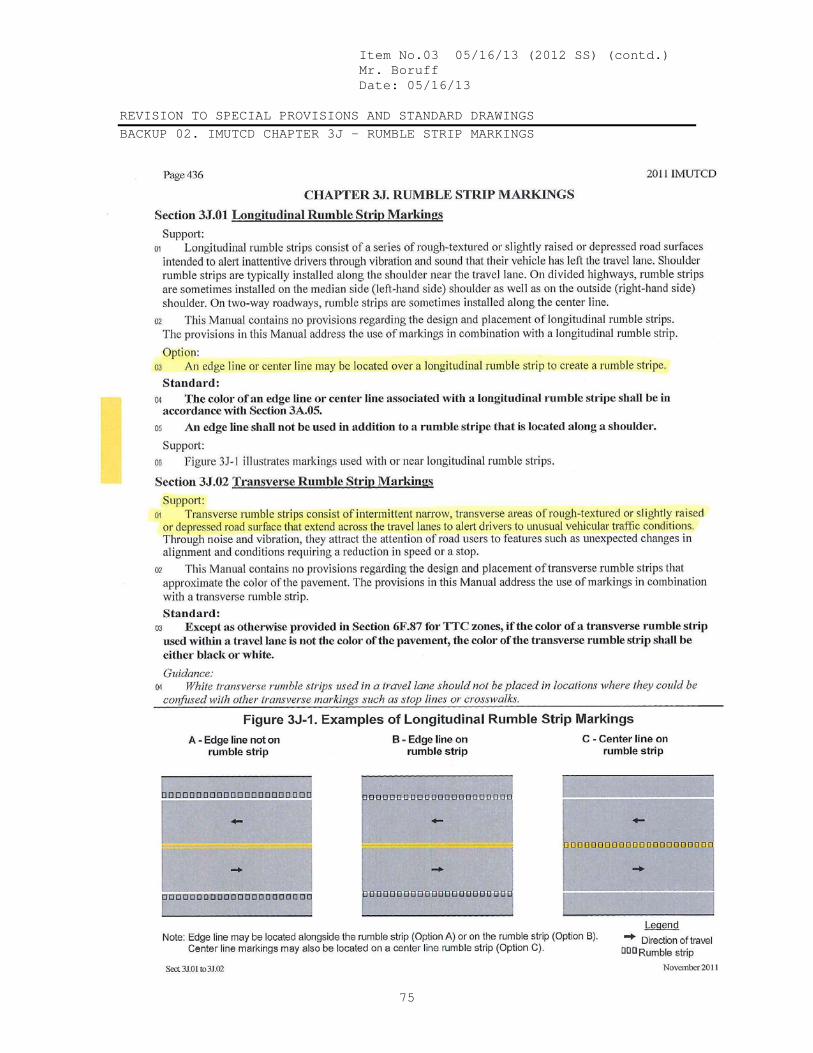
Item No.03 05/16/13 (2012 SS) (contd.) Mr. Boruff Date: 05/16/13 REVISION TO SPECIAL PROVISIONS AND STANDARD DRAWINGS BACKUP 02. IMUTCD CHAPTER 3J - RUMBLE STRIP MARKINGS
75
Item No.03 05/16/13 (2012 SS) (contd.) Mr. Boruff Date: 05/16/13 COMMENTS AND ACTION XXX-X-XXX LONGITUDINAL RUMBLE STRIPES 606-R-563 MILLED CENTERLINE CORRUGATIONS 606-R-563d MILLED CENTERLINE CORRUGATIONS 808-MLRS-01 CENTERLINE LONGITUDINAL RUMBLE STRIPE 808-MLRS-02 EDGELINE LONGITUDINAL RUMBLE STRIPE 808-MLRS-03 LONGITUDINAL RUMBLE STRIPES AT INTERSECTION, DRIVE, OR RAILROAD CROSSING
76
DISCUSSION: Mr. Boruff presented this item and directed the committee’s attention to the revisions to this proposal, which were sent out to the members earlier this week. Mr. Boruff explained the intention of this proposal which revises 606 and will enable the application of corrugations along the centerlines, as well as along the edge of pavement and shoulders. Mr. Cales offered that long ago, rumble strips were defined as raised, and corrugations were depressed – are we changing the terminology? Mr. Bruno explained that the MUTCD defines rumble strips as milled corrugations and that the term “corrugations” seems to be specific only to Indiana. Mr. Pankow pointed out the differences in terminology between the specs and the standard drawings. Mr. Miller agreed that the terms should be consistent. Mr. Holtz agreed that having the corrugations in the centerline changes the behavior of the driver, in a positive way. Ms. Phillips inquired about how and when this can be applied, depending on the size of the project and the lane width. Industry stated that the rumble stripes are as effective as RPM’s. Industry also pointed that maintenance has been an issue with RPM’s. These strips could be a benefit to both safety and maintenance. During the retrofit, only the lens would be removed from the RPM, not the castings. Mr. Lee reminded the group of the fog seal issue. Mr. Prather offered that he would like to see the fog seal portion become its own separate stand-alone pay item. Mr. Pankow added that it would then be one more thing that would need to be measured. Mr. Pankow suggested leaving the liquid asphalt reference as it is for now. Mr. Prather offered that he will make revisions to existing RSP’s for submission in the future to address the fog seal issue. Mr. Miller stated that he has some concerns about including the fog sealing with the rumble stripes. Other states have done rumble stripes – what do they do? Have we done enough fog sealing and will the paint stripes still perform effectively? Mr. Prather stated that other states most likely do not fog their rumble stripes. Also, cutting corrugations into the weakest part of the pavement, the centerline, could be problematic. Mr. Holtz stated that he is in favor of fog sealing all milled corrugations. Mr. Prather offered an example of fog seal over corrugations and then painted with Waterborne paint (SR 38 in the Crawfordsville District) and that after two years it is still performing rather well. Mr. Prather also offered a description of how a job performs when the fog seal (AE-F, or AE-NT)is applied correctly, and when it is not. Mr. Walker and Mr. Prather further described the potential damages due to water infiltration in joint areas, and the importance of properly sealing those areas. Mr. Miller reminded the committee that fog sealing and painting are issues which are separate from the issue being discussed today. Mr. Boruff moved that this item be approved as revised along with the revisions shown on the drawings.
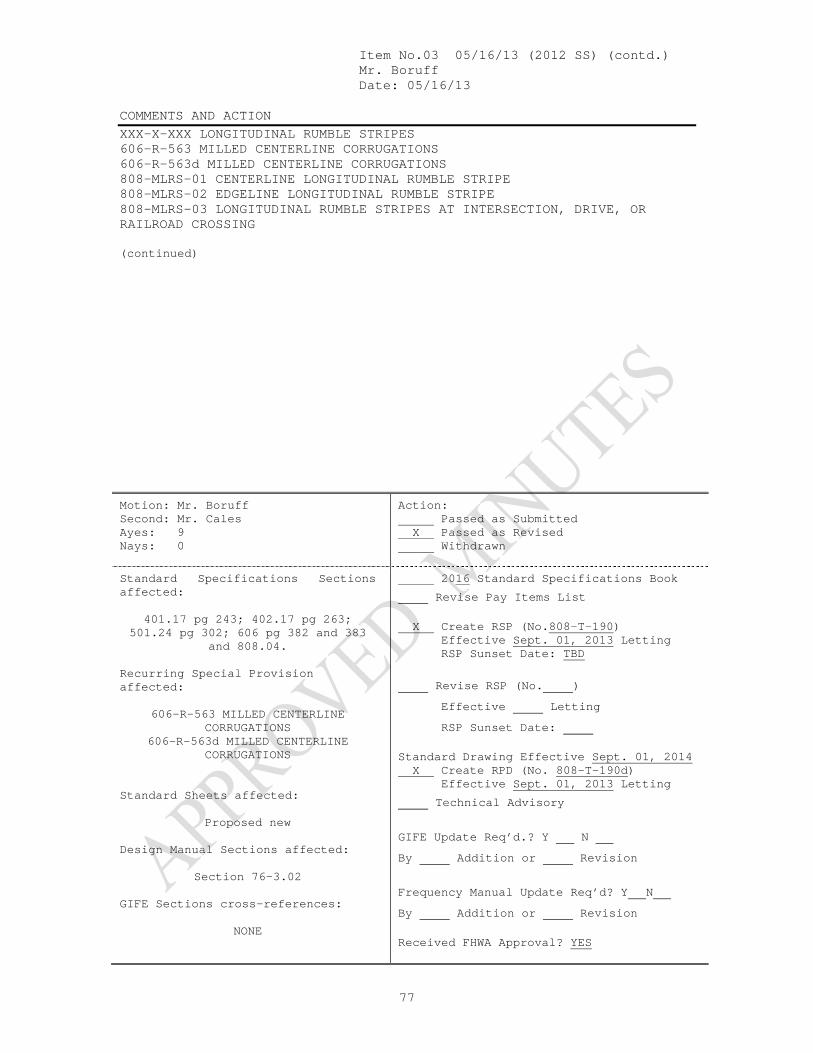
Item No.03 05/16/13 (2012 SS) (contd.) Mr. Boruff Date: 05/16/13 COMMENTS AND ACTION XXX-X-XXX LONGITUDINAL RUMBLE STRIPES 606-R-563 MILLED CENTERLINE CORRUGATIONS 606-R-563d MILLED CENTERLINE CORRUGATIONS 808-MLRS-01 CENTERLINE LONGITUDINAL RUMBLE STRIPE 808-MLRS-02 EDGELINE LONGITUDINAL RUMBLE STRIPE 808-MLRS-03 LONGITUDINAL RUMBLE STRIPES AT INTERSECTION, DRIVE, OR RAILROAD CROSSING
77
(continued)
Motion: Mr. Boruff Second: Mr. Cales Ayes: 9 Nays: 0
Action: Passed as Submitted X Passed as Revised Withdrawn
Standard Specifications Sections affected:
401.17 pg 243; 402.17 pg 263;
501.24 pg 302; 606 pg 382 and 383 and 808.04.
Recurring Special Provision affected:
606-R-563 MILLED CENTERLINE CORRUGATIONS
606-R-563d MILLED CENTERLINE CORRUGATIONS
Standard Sheets affected:
Proposed new Design Manual Sections affected:
Section 76-3.02
GIFE Sections cross-references:
NONE
2016 Standard Specifications Book
Revise Pay Items List X Create RSP (No.808-T-190) Effective Sept. 01, 2013 Letting RSP Sunset Date: TBD
Revise RSP (No. ) Effective Letting RSP Sunset Date: Standard Drawing Effective Sept. 01, 2014 X Create RPD (No. 808-T-190d) Effective Sept. 01, 2013 Letting
Technical Advisory
GIFE Update Req’d.? Y N By Addition or Revision
Frequency Manual Update Req’d? Y N By Addition or Revision Received FHWA Approval? YES

Mr. Keefer Date: 05/16/13 SPECIFICATION, SPECIAL PROVISIONS AND DRAWINGS REVISION TO STANDARD SPECIFICATIONS
78
PROPOSAL TO STANDARDS COMMITTEE
PROBLEM(S) ENCOUNTERED: Contractors request to be paid for plan quantity (CIB Schedule of Pay Items bid quantity) of "electrical signal or loop lead-in cable" if placed quantity is less than plan quantity by less than 25% difference, referring to Specification 805.15, and complain that INDOT is willing to pay plan quantity when placed quantity is greater than plan quantity by less than 25% difference, but not inclined in case of underrun of placed quantity. PROPOSED SOLUTION: The original intent was to reduce the need for field measurements, but measurements are needed anyway to confirm/deny the 25% limit for plan quantity (CIB Schedule of Pay Items bid quantity) payment. Proposed solution is to eliminate 805.15, lines 470-472, and add word "All" before word "Signal" in line 467. APPLICABLE STANDARD SPECIFICATIONS: 805.15 APPLICABLE STANDARD DRAWINGS: None APPLICABLE DESIGN MANUAL SECTION: None APPLICABLE SECTION OF GIFE: None APPLICABLE RECURRING SPECIAL PROVISIONS: None PAY ITEMS AFFECTED: Signal Cable, as per Specification 805.15 Submitted By: Jim Keefer Title: Fort Wayne DCD Organization: INDOT Phone Number: (260)969-8245 Date: 04-30-2013 APPLICABLE SUB-COMMITTEE ENDORSEMENT: None

Item No.04 05/16/13 (2012 SS) (contd.) Mr. Keefer Date: 05/16/13 REVISION TO STANDARD SPECIFICATIONS SECTION 805 – TRAFFIC SIGNALS 805.15 METHOD OF MEASUREMENTS
79
The Standard Specifications are revised as follows: SECTION 805, BEGIN LINE 466, DELETE AND INSERT AS FOLLOWS: Conduit of the type specified will be measured by the linear foot (meter) from outside to outside of foundations. All Ssignal cable and signal interconnect cable will be measured by the linear foot (meter). The accepted quantities for payment for electrical signal or loop lead-in cable will be the quantities shown in the Schedule of Pay Items. Such quantities may be corrected if they are in error by more than 25%.
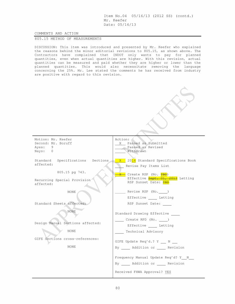
Item No.04 05/16/13 (2012 SS) (contd.) Mr. Keefer Date: 05/16/13 COMMENTS AND ACTION 805.15 METHOD OF MEASUREMENTS
80
DISCUSSION: This item was introduced and presented by Mr. Keefer who explained the reasons behind the minor editorial revisions to 805.15, as shown above. The Contractors have complained that INDOT only wants to pay for planned quantities, even when actual quantities are higher. With this revision, actual quantities can be measured and paid whether they are higher or lower than the planned quantities. This would also necessitate removing the language concerning the 25%. Mr. Lee stated the comments he has received from industry are positive with regard to this revision.
Motion: Mr. Keefer Second: Mr. Boruff Ayes: 9 Nays: 0
Action: X Passed as Submitted Passed as Revised Withdrawn
Standard Specifications Sections affected:
805.15 pg 743.
Recurring Special Provision affected:
NONE
Standard Sheets affected:
NONE
Design Manual Sections affected:
NONE
GIFE Sections cross-references:
NONE
X 2014 Standard Specifications Book
Revise Pay Items List X Create RSP (No. TBD) Effective Sept. 01, 2013 Letting RSP Sunset Date: TBD
Revise RSP (No. ) Effective Letting RSP Sunset Date:
Standard Drawing Effective Create RPD (No. ) Effective Letting Technical Advisory
GIFE Update Req’d.? Y N By Addition or Revision
Frequency Manual Update Req’d? Y N By Addition or Revision Received FHWA Approval? YES