Embed Size (px)
Citation preview
APPROVED FOR PUBLIC RELEASEDISTRIBUTION UNLIMITED
MASSACHUSETTS INTITUTE OF TECHNOLOGY VLSI PUBLICATIONS
AD-A225 475 OT1C rj u COPY
VLSI Memo No. 90-600June 1990
Viscoelasticity and Creep Recovery of Polyimide Thin Films
Fairborz Maseeh and Stephen D. Senturia
Abstract
"rCreep and recovery of a polyimide thin film well below its glass transition temperature isdemonstrated through use of circular membrane bulge test. Extensive use is made of a recentlydeveloped mechanical CAD system linked to the fabrication process to model the structure. Acreep power law is used in a nonlinear finite element (FEM) analysis to fit the experimental results,thereby measuring the viscoelastic properties.
DTICELECTEAUG 22 1990
Microsystems Massachusetts Cambridge /7) Room 39-321Technology Institute Massachusetts TelephoneLaboratories of Technology 02139 (617) 253-0292
90 08 21 052
Acknowledgements
This work was supported in part by the Defense Advanced Research Projects Agency underContract #MDA972-88-K-0008. Microfabrication was canied out in the Microsystems TechnologyLaboratories and the MIT Center for Materials Science and Engineering which is supported in partby the National Science Foundation under Contract #DMR-87-19217. To appear in theProceedings of the 1990 Solid State Sensors and Actuators Workshop, Hilton Head, SouthCarolina, June 1990.
Author Information
Maseeh: Teknekron Sensor Development Corporation (TSDC), 1080 Marsh Road,Menlo Park, CA 94025. (415)322-6200
Senturia: Department of Electrical Engineering and Computer Science, MIT,Cambridge, MA 02139-3931. (617)253-6869
Copyright © 1989 MIT. Memos in this series are for use inside MIT and are not 04si4ered to bepublished merely by virtue of appearing in this series. This copy is for private circuaatof only andmay not be further copied or distributed, except for government purposes, if-the paperacknowledges U. S. Government sponsorship. References to this work should be either to thepublished version, if any, or in the form "private communication." For information about the ideasexpressed hereia, contact the author directly. For information about this series, contactMicrosystems Technology Laboratories, Room 39-321, MIT, Cambridge, MA 02139-3931; (617)253-0292. Accesion For
NTIS CRA&IDTIC TABUnannounced 0JuslfIcation
.....
' ry
(I'. . ,*
VISCOELASTICITY AND CREEP RECOVERY OF POLYIMIDE THIN"* FILMS
Fariborz Maseeh and Stephen D. SenturiaMicrosystems Technology Laboratories
Massachusetts Institute of Technology, Cambridge, MA 02139
ABSTRACT
Creep and recovery of a polyimide thin film well below its glass transitiontemperature Is demonstrated through use of circular membrane bulge test. Extensive use ismade of a recently developed mechanical CAD system linked to the fabrication process tomodel the structure. A creep power law is used in a nonlinear finite element (FEM) analysisto fit the experimental results, thereby measuring the viscoelastic properties.
INTRODUCTION
Recently, polyimide films have been used as structural components of mechanicalmicrosensors and microactuators [1-3]. Polyimides, like most polymers, exhibit a timedependent mechanical response (viscoelasticity). This is potentially an important factor inthe design of mechanical structures in which polyimide is subjected to sustained loads.
Viscoelastic properties of materials are traditionally measured by uniaxial tests [4].Creep, stress-relaxation, and dynamic-loading tests are the commonly used techniques tomeasure the time-dependent analogs to elastic constants. The uniaxial Teep test consists ofmeasuring the time-dependent stretch resulting from the application of a steady axial load,and can be directly related to the viscoelastic properties. Uniaxial experiments, thougheffective for large samples, can be difficult to implement for thin films. We employ circularmembranes to perform a biaxial creep experiment in which a time-dependent deformation ismeasured under a state of biaxial stress. This technique eliminates the sample handlingproblems and offers a way to detect and measure the viscoelastic behavior of the material.The membrane data, in the form of deflection as a function of applied pressure, need furthermodeling to extract the time dependent stress vs strain results. In this work, we report oncreep and creep recovery of Dupont's commercial polyimide P12525, and present a non-linear viscoelastic model for the interpretation of the creep behavior.
SAMPLE FABRICATION AND MEASUREMENTS
The P12525 polyimide is the imidized form of the polyamic acid precursor thatresults from the reaction of benzophenone-tetracarboxylic dianhydride (BTDA) with a blendof meta-phenylenediamine (MPDA-40%) and oxydianiline (ODA-60%) [5]. The polyamicacid is supplied commercially dissolved in N-methylpyrollidone and is spin-cast, then curedto produce the polyimide. Circular polyimide membranes one inch in diameter and 5 IL.m inthickness are microfabricated using the technique described in [6]. The PI2525 precursor isspin deposited on (100) silicon substrates in multiple layers, prebaked at 130 0C for 15minutes after each layer for solvent removal and partial imidization, and then cured(imidized) at 4000 C in nitrogen for one hour. A VESPEL ring, one inch in inner diameter,1- 1/8 inch in outside diameter, and 1/16 inch thick, is mounted on the polyimide side with
epoxy, and the substrate is removed by chemical etching with an nitric-hydroflouric acidsolution. The ring, which is sufficiently large to be considered rigid, captures the state ofbiaxial stress in the film at the support. The sample is mounted in our bulge test apparatus Wand the center deflection as a function of the applied pressure is measured by tracking thefocus point using a digital micrometer attached to a microscope stage. The applied airpressure is measured by a Kulite LQ-5-516 pressure sensor calibrated for the workingpressure ranges (0 - 0.1 MPa).
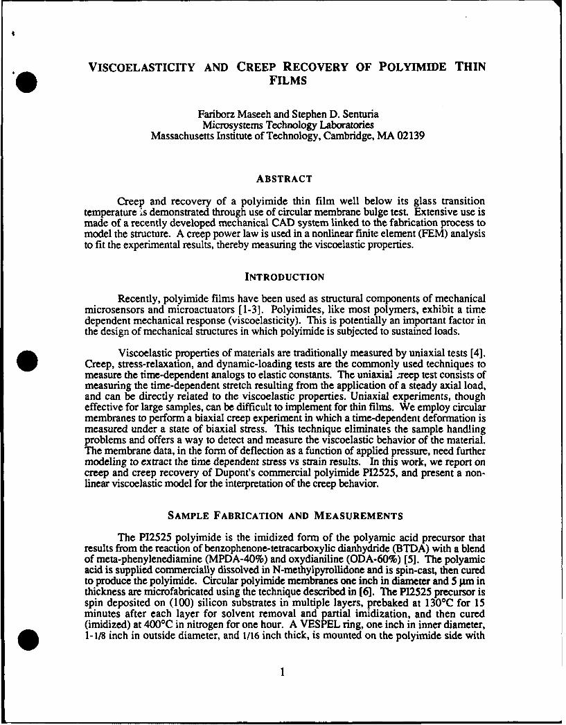
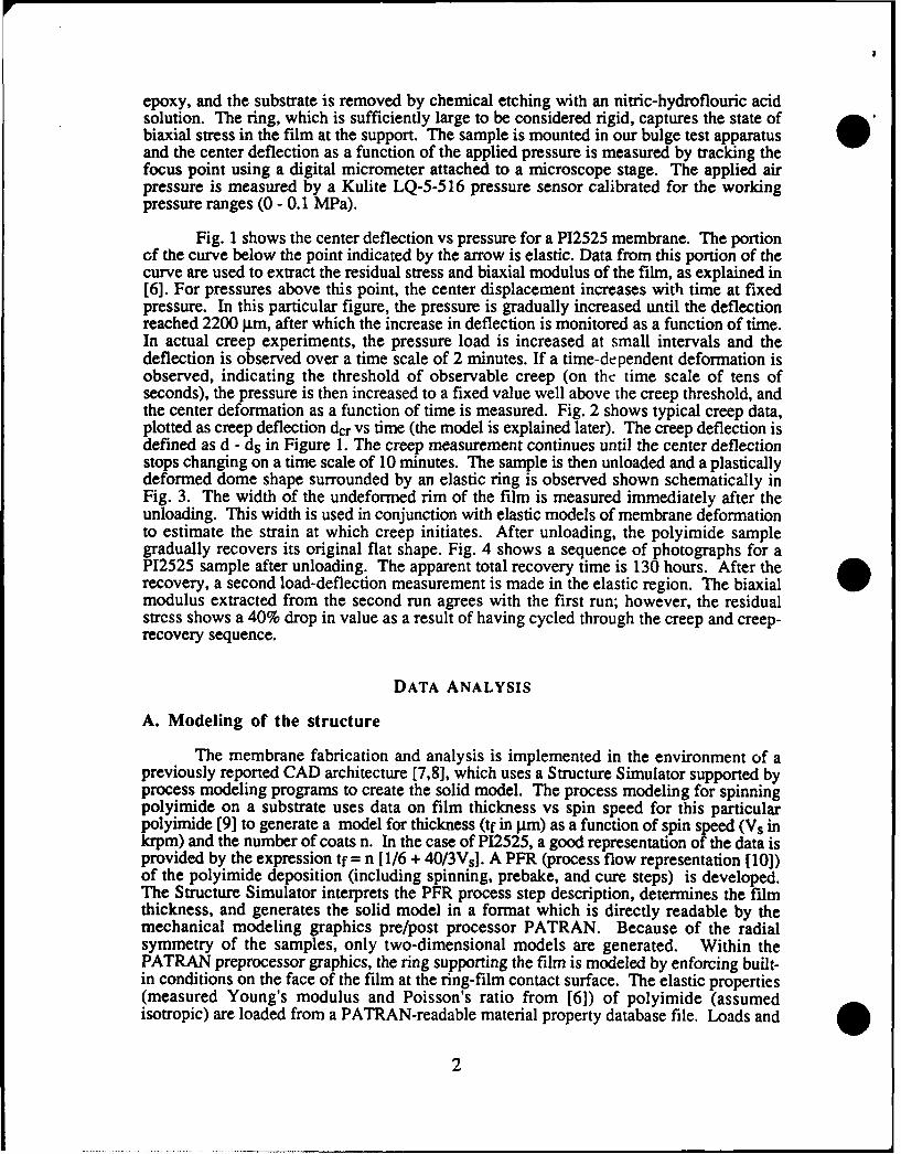
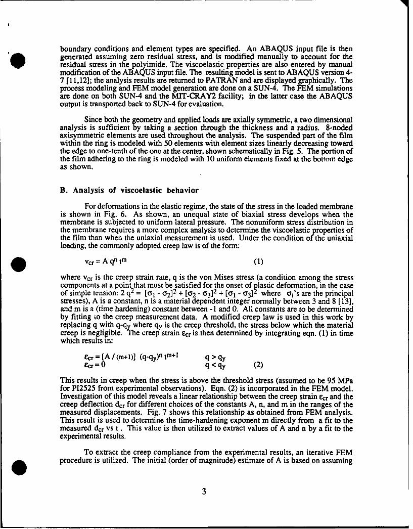
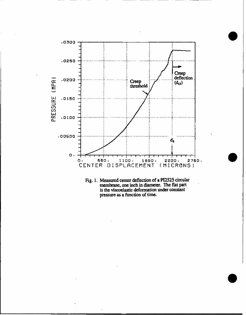
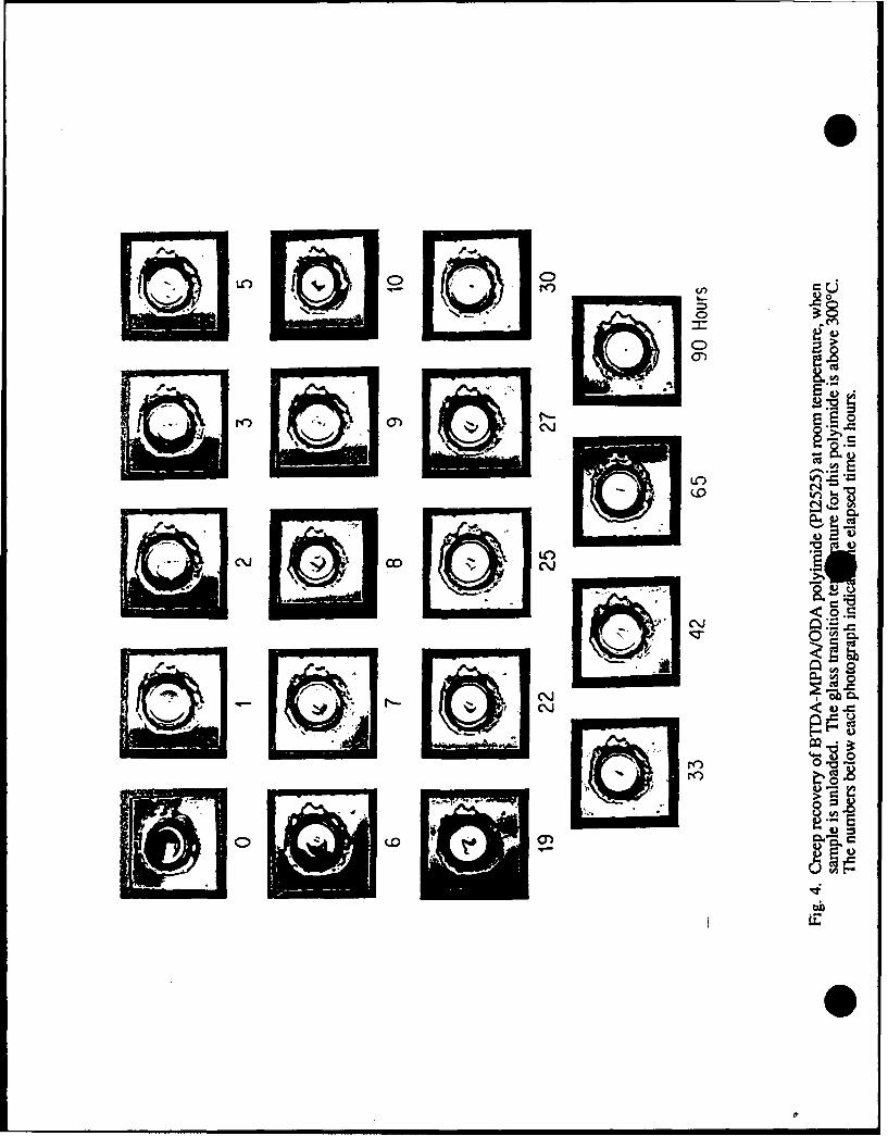
Fig. 1 shows the center deflection vs pressure for a P12525 membrane. The portionGf the curve below the point indicated by the arrow is elastic. Data from this portion of thecurve are used to extract the residual stress and biaxial modulus of the film, as explained in[6]. For pressures above this point, the center displacement increases with time at fixedpressure. In this particular figure, the pressure is gradually increased until the deflectionreached 2200 ptm, after which the increase in deflection is monitored as a function of time.In actual creep experiments, the pressure load is increased at small intervals and thedeflection is observed over a time scale of 2 minutes. If a time-dependent deformation isobserved, indicating the threshold of observable creep (on the time scale of tens ofseconds), the pressure is then increased to a fixed value well above the creep threshold, andthe center deformation as a function of time is measured. Fig. 2 shows typical creep data,plotted as creep deflection dcr vs time (the model is explained later). The creep deflection isdefined as d - ds in Figure 1. The creep measurement continues until the center deflectionstops changing on a time scale of 10 minutes. The sample is then unloaded and a plasticallydeformed dome shape surrounded by an elastic ring is observed shown schematically inFig. 3. The width of the undeformed rim of the film is measured immediately after theunloading. This width is used in conjunction with elastic models of membrane deformationto estimate the strain at which creep initiates. After unloading, the polyimide samplegradually recovers its original flat shape. Fig. 4 shows a sequence of photographs for aP12525 sample after unloading. The apparent total recovery time is 130 hours. After therecovery, a second load-deflection measurement is made in the elastic region. The biaxialmodulus extracted from the second run agrees with the first run; however, the residualstress shows a 40% drop in value as a result of having cycled through the creep and creep-recovery sequence.
DATA ANALYSIS
A. Modeling of the structure
The membrane fabrication and analysis is implemented in the environment of apreviously reported CAD architecture [7,81, which uses a Structure Simulator supported byprocess modeling programs to create the solid model. The process modeling for spinningpolyimide on a substrate uses data on film thickness vs spin speed for this particularpolyimide [9] to generate a model for thickness (tf in gm) as a function of spin speed (Vs inkrpm) and the number of coats n. In the case of P12525, a good representation of the data isprovided by the expression tf = n [1/6 + 40/3Vs]. A PFR (process flow representation [10])of the polyimide deposition (including spinning, prebake, and cure steps) is developed.The Structure Simulator interprets the PFR process step description, determines the filmthickness, and generates the solid model in a format which is directly readable by themechanical modeling graphics pre/post processor PATRAN. Because of the radialsymmetry of the samples, only two-dimensional models are generated. Within thePATRAN preprocessor graphics, the ring supporting the film is modeled by enforcing built-in conditions on the face of the film at the ring-film contact surface. The elastic properties(measured Young's modulus and Poisson's ratio from [6]) of polyimide (assumedisotropic) are loaded from a PATRAN-readable material property database file. Loads and
2
boundary conditions and element types are specified. An ABAQUS input file is thengenerated assuming zero residual stress, and is modified manually to account for theresidual stress in the polyimide. The viscoelastic properties are also entered by manualmodification of the ABAQUS input file. The resulting model is sent to ABAQUS version 4-7 [11,12]; the analysis results are returned to PATRAN and are displayed graphically. Theprocess modeling and FEM model generation are done on a SUN-4. The FEM simulationsare done on both SUN-4 and the MIT-CRAY2 facility; in the latter case the ABAQUSoutput is transported back to SUN-4 for evaluation.
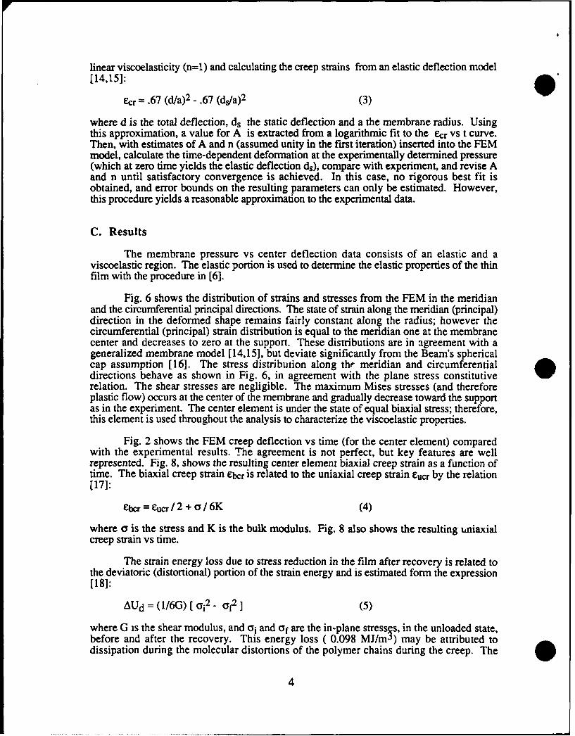
Since both the geometry and applied loads are axially symmetric, a two dimensionalanalysis is sufficient by taking a section through the thickness and a radius. 8-nodedaxisymmetric elements are used throughout the analysis. The suspended part of the filmwithin the ring is modeled with 50 elements with element sizes linearly decreasing towardthe edge to one-tenth of the one at the center, shown schematically in Fig. 5. The portion ofthe film adhering to the ring is modeled with 10 uniform elements fixed at the bottom edgeas shown.
B. Analysis of viscoelastic behavior
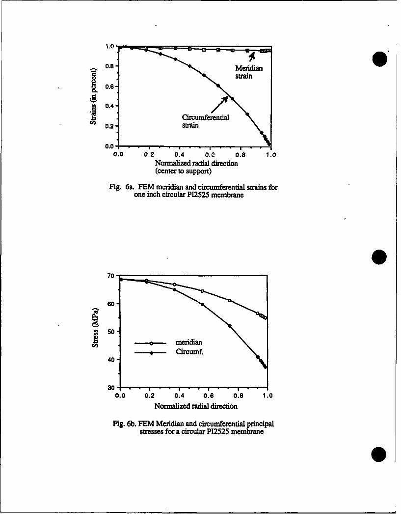
For deformations in the elastic regime, the state of the stress in the loaded membraneis shown in Fig. 6. As shown, an unequal state of biaxial stress develops when themembrane is subjected to uniform lateral pressure. The nonuniform stress distribution inthe membrane requires a more complex analysis to determine the viscoelastic properties ofthe film than when the uniaxial measurement is used. Under the condition of the uniaxialloading, the commonly adopted creep law is of the form:
vcr = A qn tm (1)
where vcr is the creep strain rate, q is the von Mises stress (a condition among the stresscomponents at a point that must be satisfied for the onset of plastic deformation, in the caseof simple tension: 2 q2 = [01 - a2]2 + [a2 - 03]2 + [y1 - 03]2 where oi's are the principalstresses), A is a constant, n is a material dependent integer normally between 3 and 8 [13],and m is a (time hardening) constant between -1 and 0. All constants are to be determinedby fitting io the creep measurement data. A modified creep law is used in this work byreplacing q with q-qy where qY is the creep threshold, the stress below which the materialcreep is negligible. The creep strain Ecr is then determined by integrating eqn. (1) in timewhich results in:
= [A / (m+1)] (q-qy)n tm+I q > qyEcr = 0 q< qy (2)
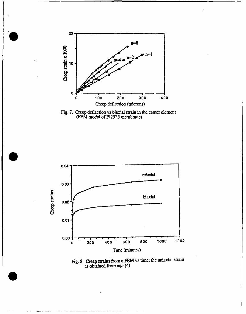
This results in creep when the stress is above the threshold stress (assumed to be 95 MPafor P12525 from experimental observations). Eqn. (2) is incorporated in the FEM model.Investigation of this model reveals a linear relationship between the creep strain &cr and thecreep deflection dcr for different choices of the constants A, n, and m in the ranges of themeasured displacements. Fig. 7 shows this relationship as obtained from FEM analysis.This result is used to determine the time-hardening exponent m directly from a fit to themeasured dcr vs t. This value is then utilized to extract values of A and n by a fit to theexperimental results.
To extract the creep compliance from the experimental results, an iterative FEMprocedure is utilized. The initial (order of magnitude) estimate of A is based on assuming
3
linear viscoelasticity (n=l) and calculating the creep strains from an elastic deflection model
[14,15]:
ecr = .67 (d/a)2 - .67 (ds/a)2 (3)
where d is the total deflection, ds the static deflection and a the membrane radius. Usingthis approximation, a value for A is extracted from a logarithmic fit to the ecr Vs t curve.Then, with estimates of A and n (assumed unity in the first iteration) inserted into the FEMmodel, calculate the time-dependent deformation at the experimentally determined pressure(which at zero time yields the elastic deflection ds), compare with experiment, and revise Aand n until satisfactory convergence is achieved. In this case, no rigorous best fit isobtained, and error bounds on the resulting parameters can only be estimated. However,this procedure yields a reasonable approximation to the experimental data.
C. Results
The membrane pressure vs center deflection data consists of an elastic and aviscoelastic region. The elastic portion is used to determine the elastic properties of the thinfilm with the procedure in [6].
Fig. 6 shows the distribution of strains and stresses from the FEM in the meridianand the circumferential principal directions. The state of strain along the meridian (principal)direction in the deformed shape remains fairly constant along the radius; however thecircumferential (principal) strain distribution is equal to the meridian one at the membranecenter and decreases to zero at the support. These distributions are in agreement with ageneralized membrane model [14,15], but deviate significantly from the Beam's sphericalcap assumption [16]. The stress distribution along the meridian and circumferentialdirections behave as shown in Fig. 6, in agreement with the plane stress constitutiverelation. The shear stresses are negligible. The maximum Mises stresses (and thereforeplastic flow) occurs at the center of the membrane and gradually decrease toward the supportas in the experiment. The center element is under the state of equal biaxial stress; therefore,this element is used throughout the analysis to characterize the viscoelastic properties.
Fig. 2 shows the FEM creep deflection vs time (for the center element) comparedwith the experimental results. The agreement is not perfect, but key features are wellrepresented. Fig. 8, shows the resulting center element biaxial creep strain as a function oftime. The biaxial creep strain elbcr is related to the uniaxial creep strain Eucr by the relation[17]:
ebcr = Eucr / 2 + o / 6K (4)
where a is the stress and K is the bulk modulus. Fig. 8 also shows the resulting ,niaxialcreep strain vs time.
The strain energy loss due to stress reduction in the film after recovery is related tothe deviatoric (distortional) portion of the strain energy and is estimated form the expression[181:
AUd = (1/6G) [ 0i 2 - f2 ] (5)
where G is the shear modulus, and ai and aof are the in-plane stress s, in the unloaded state,before and after the recovery. This energy loss ( 0.098 MJ/mg) may be attributed todissipation during the molecular distortions of the polymer chains during the creep. The
4
effects of elevated temperature anneals on this energy loss has not been investigated, but
would be interesting.
CREEP RECOVERY
The creep recovery phenomenon illustrated in Figure 4 (shape memory effect) hasbeen observed in polymers that are plastically deformed below their Tg when they arethermally loaded near or above their Tg; see e.g. [19,20]. In the experiment reported here,the polyimide is exhibiting creep recovery about 300 'C below its glass transition. Belowthe glass transition temperature, a polymer material must overcome two distinct sources ofresistance before inelastic flow may occur [21,22]: (1) the material must be stressed aboveits intermolecular resistance to segment rotation (restrictions imposed on molecular chainmotion by the neighboring chains), and (2) once the material begins to flow, molecularalignment occurs, altering the configurational entropy of the material. This entropy change,by analogy to the rubbery regime, may be related to the evolution of back stresses which canresult in the recovery of the polymer [23]. The energy loss after shape recovery may beattributed to dissipating effects during reorientation of the polyimide chains.
Quantitative modeling of the recovery phenomenon will be reported elsewhere. Theyield line for the recovering portion does not remain circular, and the contour for thedeformed region is not easily measured without film disturbance. Qualitatively, it isobserved that the recovery is temperature dependent. The sample recovers faster when thetemperature is elevated. Humidity effects have not been investigated.
CONCLUSION
The use of circular membranes in neasuring the viscoelastic and plastic materialproperties of thin films has some advantages over the uniaxial techniques. The membranesare edge free and therefore less susceptible to cracks which can prohibit observation of yieldin glassy materials such as P12525. The maximum stress region (center point) is alsoidentified in advance; hence the viscoelastic properties of thin films can be observed withouthaving to yield or creep the entire sample. However, the analysis to determine theviscoelastic properties is more cumbersome. This paper has presented a first attempt at suchdata analysis, and has determined that the creep compliance of PI2525 is a very nonlinearfunction of the stress (n = 8), and also requires a threshold strain before creep begins.
ACKNOWLEDGEMENTS
The authors wish to gratefully acknowledge Profs. Ali S. Argon, and David M.Parks of Mechanical Engineering Dept., Profs. Jerome J. Connor, and Shyan Sunder ofCivil Engineering Dept. at MIT for their many technical remarks. We thank Duane S.Boning for the polyimide deposition PFR, and R. M. Harris for the structure simulator solidmodels. We extend our gratitude to HKS Inc. for the ABAQUS academic license andtechnical support, and to the MIT Super Computing Facilities for providing assistance forCRAY2 usage. This work was supported in part by Defence Advanced Research ProgramAgency under contract no. MDA972-88-k-0008. Microfabrication was carried out in theMicrosystems Technology Laboratories and the MIT center for Materias Science andEngineering, which is supported in part by the National Science Foundation under ContractNo. DMR-87-19217.
5
REFERENCES
[1] M. A. Schmidt, R. T. Howe, S. D. Senturia, and J. H. Haritonidis, "Design andcalibration of a microfabricated floating element shear-stress sensor", IEEE Trans.Elec. Dev., v. 35, June 1988, p. 750.
[2] M. G. Allen, M. Scheidl, R. L. Smith," Design and fabrication of movable siliconplates suspended by flexible supports", Proceedings of IEEE Micro ElectroMechanical Systems, Salt Lake City, Utah, Feb. 1989, p. 7 6 .
[3] M. Mehregany, R. Mahadevan, and K. J. Gabriel, "Application of electricmicroactuators to silicon micromechanics", Proceedings of Transducers'89, June1989, Montreux, Switzerland.
[4] R. Mohan and D. F. Adams, "Nonlinear creep-recovery response of a polymer matrix
and its composites", Exp. Mech., Sept. 1985, p. 262.
[5] P. V. Nagarkar, percentages from an XPS study, to be published.
[6] F. Maseeh, and S. D. Senturia,"Elastic properties of polyimide thin films", Polyimidese Materials. Chemistry and Characterization, ed. by C. Feger, M. M. Khojasteh and J.E. Grath, Elsevier, Amsterdam, 1989, p. 575.
[7] F. Maseeh, R. M. Harris, and S. D. Senturia,"A CAD architecture formicroelectromechanical design", Proceedings of IEEE Micro Electro MechanicalSystems, Napa Valley, CA, Feb. 1990, p. 44.
[8] R. M. Harris, F. Maseeh, and S. D. Senturia, "Automatic generation of a 3-D solidmodel of a microfabricated structure", Proceedings of this conference.
[9] D. Volfson, private communications.
[10] D. S. Boning, private communication.
[11] H. D. Hibbitt, "ABAQUS/EPGEN, a general purpose finite element code withemphasis on nonlinear applications", Nuc. Eng. Des., vol. 77, 1984, p. 271.
[12] ABAQUS User Manual, Release 4-7, HKS, Providence, RI.
[13] A.R. S. Ponter, and F. A. Leckie, "The application of energy theorems to bodieswhich creep in the plastic range", J. Appl. Mech. Sept. 1970, p. 753.
[14] A. E. Green, and J. E. Adkins, Large elastic deformations, Clarendon press, Oxford,1970, p. 13 3 .
[15] T. Tsakalakos, "A comparison of theory and experiment for isotropic and anisotropicfilms", Thin solid films, v. 75, 1981, p. 293.
[16] J. W. Beams, "Mechanical properties of thin films of gold and silver", in C. A.Neugebauer, J. B. Newkirk, and D. A. Vermilyea, ed., Structure and Properties ofThin Films, Wiley & Sons, New York, 1959, p. 183.
[17] L. E. Nielsen, Mechanical properties of polymers and composites, v. 1, MarcelDekker, Inc., NY, 1974, p.121.
6
[18] E. F. Byars, R. D. Snyder, and H. L. Plants, Engineering mechanics of deformablebodies, Fourth ed., Harper & Row, 1983, p. 417.
[19] Y. P. Khanna, R. Kumar, and A. C. Reimschuessel, "Memory effects in polymers HII.Process history vs crystallization rate of Nylon 6-comments on the origin of memoryeffect", Pol. Eng. & Sc., v. 28, No. 24, 1988, p. 1607.
[20] A. Charlesby, and B. Kidric, "Memory effect in irradiated polymers", Radiat. Phys.Chem., v. 30, No. 1, 1987, p. 67.
[21] A. S. Argon, "A theory for the low-temperature plastic deformation of glassypolymers", Phil. Mag., vol. 28, 1973, p. 39.
[22] R. N. Howard, and G. Thackray, "The use of a mathematical model to describeisothermal stress-strain curves in glassy thermoplastics", Proc. Royal Soc. vol. 302,1968, p. 453.
[23] M. C. Boyce, D. M. Parks, and A. S. Argon, "Large inelastic deformation of glassypolymers. Part I: rate dependent constitutive model", Mech. Mat., vol. 7, 1988, p. 15.
7
.0300
.0250
a: .020 Crep :(dcr)threshold,
LJ .0150 -
uJn::.0100----------------------
.0 . ------------- ---------- ----- ----- i-----0 . 1 j j ,j , I
0. 550. 1100. 1650. 2200. 2750.
CENTER DISPLRCEMENT (MICRONS)
Fig. 1. Measured center deflection of a PI2525 circularmembrane, one inch in diameter. The flat partis the viscoelastic deformation under constantpressure as a function of time.
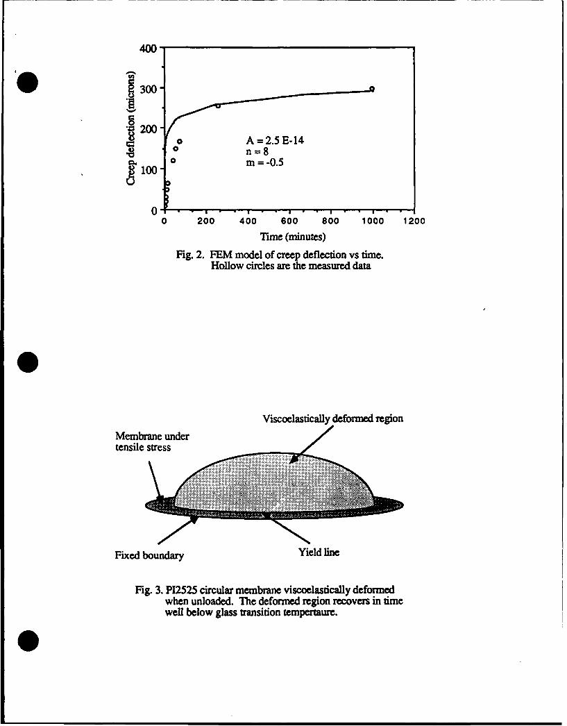
400-
300
~200O A= 2.E-14
0 200 400 600 800 1000 1200
Time (minutes)
Fig. 2. FEM model of creep deflection vs time.Hollow circles are the measured dam
Viscoelastically deformed regionMembrane under/
tensile stress
..... ....+ ----i
Fixed boundary Yield line
Fig. 3. P12525 circular membrane viscoelastically deformedwhen unloaded. The deformed region recovers in timewell below glass transition tempertaure.
L1tOI C> C). U
U
~EvC
-AM.A 0 91:
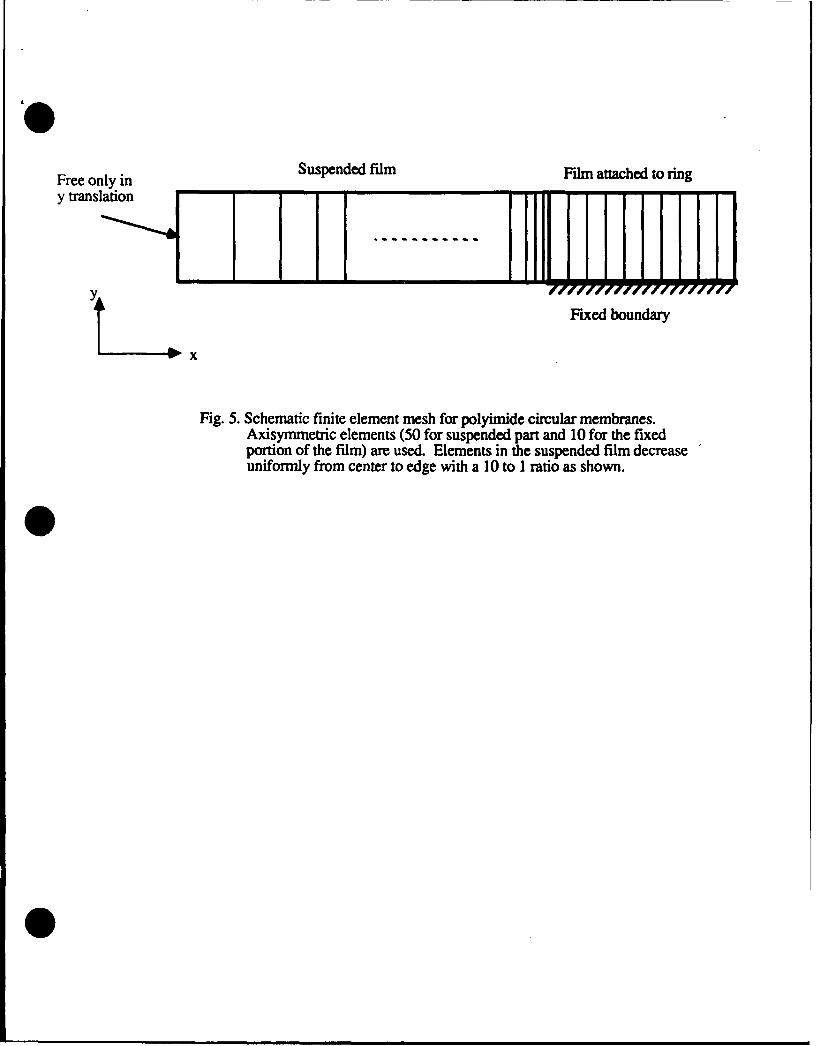
Free only in Suspended film Film attached to ringy translation
Y Fixed boundary
x
Fig. 5. Schematic finite element mesh for polyimide circular membranes.Axisymmetric elements (50 for suspended part and 10 for the fixedportion of the film) are used. Elements in the suspended film decreaseuniformly from center to edge with a 10 to I ratio as shown.
__0.8-Mrda
jo. 6 -
0.4-
0.2. s~mif
0.0 0.2 0.4 0. C 0.8 1.0Normalized radial direction(center to support)
Fig. 6a. FEM meridian and circumferential sarains forone inch circular PI2525 membrane
60-
~50-
-o-- meridian.-.----. Circumf.
40-
0.0 0.2 0.4 0.6 0.8 1.0
Normalized radial dircton
Fig. 6b. FEM Meridian and circumferential principalstresses for a circular PI2525 membrane
20-
n=8
nJ4,10-
0100 200 300 4;0
Creep deflection (microns)
Fig. 7. Creep deflection vs biaxial strain in the center element(FEM model of P12525 membrane)
0.04
uniaxWl
0.031 .
0.01
0.000 2;0 400 600 800 1000 1200
Time (minutes)
Fig. 8. Creep sa-ains from a FEM vs time; the uniaxial strainis obtained from OPn (4)