Embed Size (px)
Citation preview
Article
Appropriate Forming Conditions for Hydroxyapatite-Bioactive Glass Compact Scaffold Wassanai Wattanutchariya1,a,*, Jidapah Ruennareenard1,b, and Pana Suttakul2,c
1 Advanced Manufacturing Technology Research Center, Department of Industrial Engineering, Biomedical Engineering Center, Faculty of Engineering, Chiang Mai University, Chiang Mai 50200, Thailand 2 Department of Mechanical Engineering, Faculty of Engineering, Chiang Mai University, Chiang Mai 50200, Thailand E-mail: [email protected] (Corresponding author), [email protected], [email protected] Abstract. Biomaterials, such as Hydroxyapatite (HA) and Bioactive glass (BG) have been increasingly implemented in bone substitution due to their biocompatibility and close resemblance to the mineralized phase of human bone. Furthermore, biomaterials can be synthesized from natural sources with calcium-based skeletal structures. In this study, HA and BG were synthesized from bovine bone and mollusk shell, and mixed together to form HA-BG composite biomaterial. Then, the mixtures were compressed into a compact scaffold with dimension of 8×6×8 mm3, sintered at 1,000 ˚C for 3 hours and cooled down to room temperature. The compressive strengths of all specimens were evaluated using a universal testing machine. Experimental design was implemented to evaluate the significant factors of forming conditions on the mechanical property of the scaffold. The results revealed that all forming factors have a significant effect on the mechanical property of the composite scaffolds. Consequently, the highest compressive strength (136.92 MPa) was obtained from the scaffold with a 5.85 wt% of BG, 23.41 MPa of pressure and 65.64 seconds of holding time. In addition, Finite Element (FE) modeling was performed to simulate the HA-BG plate under combined loading, and showed that stresses were concentrated near the fracture site and the screw holes. Keywords: Hydroxyapatite, bioactive glass, compressive strength, experimental design, finite element analysis.
ENGINEERING JOURNAL Volume 20 Issue 3 Received 21 August 2015 Accepted 19 November 2015 Published 19 August 2016 Online at http://www.engj.org/ DOI:10.4186/ej.2016.20.3.123
brought to you by COREView metadata, citation and similar papers at core.ac.uk
provided by Engineering Journal (Faculty of Engineering, Chulalongkorn University, Bangkok)
DOI:10.4186/ej.2016.20.3.123
124 ENGINEERING JOURNAL Volume 20 Issue 3, ISSN 0125-8281 (http://www.engj.org/)
1. Introduction Bioactive ceramics have been developed and implemented in medical application as a bone substitute material for fractures. Calcium phosphate ceramics, particularly hydroxyapatite (HA: Ca10(PO4)6(OH)2) and bioactive glass (BG: 45S5), were widely implemented as implant materials due to their biocompatibility and close resemblance to the mineralized phase of human bone structures [1], which can stimulate the formation of new bone with the surrounding tissue [2]. Furthermore, HA and BG can be synthesized from natural sources with calcium-based structures such as bovine bone, mollusk shell or corals [3-4]. Therefore, these materials may be regarded as cost-effective biomaterial for bone tissue engineering for bone graft application.
HA is currently used as implant material in orthopedic surgery and dental implant due to its biocompatibility, osteoconductivity, and chemical similarity to the human skeletal system [5]. It has calcium to phosphate ratio of 1.67, which is homologous to natural human bone [6]. However, bulk HA cannot be used as load-bearing implants because of low mechanical properties such as high brittleness [5, 7-8]. For this reason, researchers have previously attempted to combine HA with BG to develop composite biomaterials structure with better mechanical and biological properties [9]. This combination may be achieved through sintering, though sintering above 597 ˚C will cause crystallization of amorphous BG [10]. The Na2Ca2Si3O9 crystalline phase formed improves the mechanical property [11] and bioactive response [12].
Finite element analysis (FEA) has played a role important in orthopedic surgery. A numerical model based on the FEA programs such as ANSYS, ABAQUS, MSC/MARC, and SolidWorks, etc. [13-16] is frequently used to predict complicated problems, complex geometry and boundary condition. Consider the scenario of a fractured bone supported by a plate. It would be expected that stresses are distributed on the supported plate. To analyze this distribution, it is necessary to determine the mechanical properties of the plate such as the Poisson's ratio and Young’s modulus [17]. Furthermore, FEA is also commonly used to analyze problems in other biomechanical fields such as forces acting on screw implants, drilling and tapping processes (to prevent drill-bit breakthrough of bone) as well as making predictions in orthodontics [13-14, 16].
Therefore, this work aims to investigate and identify appropriate pressing conditions for a HA-BG compact scaffold using the experimental design based on the Response Surface Method (RSM). These forming factors consist of mixing ratio, pressure and holding time. The optimal condition was evaluated based on an average compressive strength. Finally, the actual mechanical properties of the compact scaffold were used to configure a simulated finite element model under applied force.
2. Methodology 2.1. Preparation of HA In this experiment, HA was synthesized from bovine bone. First of all, the bovine bone was cut into small pieces and soaked in hydrogen peroxide (H2O2) solution for 2 days to remove the ligaments and tissues. Then, the small pieces of bones were boiled into water to eliminate organic substances and collagen. Next, these bones were kept in the hot air oven at 120 °C for 7 hours to reduce their moisture content. The dried bones were calcined at 850 °C for 3 hours [2-3], before being grinded into powder by a high speed ball
milling machine until the average particle size is less than 20 μm, as shown in Fig. 1(a). 2.2. Preparation of BG The BG developed by Larry L. Hench [18] composes of 45 wt% SiO2, 24.5 wt% Na2O, 24.5 wt% CaO and 6 wt% P2O5 is also known as Bioglass® 45S5. In the present study, the BG was synthesized from both chemical and natural substances: silicon oxide (Merck), sodium oxide (Merck), calcium oxide (synthesized using mollusk shell) and phosphorus pentoxide (Sigma-Aldrich, reagent grade 97%). An appropriate ratio of reagents was thoroughly mixed using a magnetic stirrer and poured into a ceramics crucible. This was heated at 1,100 °C for 2.5 hours using a furnace, as BG is known to start melting at 1,100 °C [19]. In this
experiment, an agate mortar was used to reduce the particle size of material down to less than 20 μm as shown in Fig. 1(b).
DOI:10.4186/ej.2016.20.3.123
ENGINEERING JOURNAL Volume 20 Issue 3, ISSN 0125-8281 (http://www.engj.org/) 125
2.3. Biomaterial Characterization To characterize the crystal phase in sintered BG, a small sample of pulverized BG was heated at 770 °C with 1 hour holding time to ensure formation of crystals [20]. The synthesized biomaterials were evaluated using X-Ray diffraction analysis (XRD) for phase identification. The specimen was examined using a
Rigaku MiniFlex II desktop x-ray diffractometer using CuKα radiation. The data was recorded based on 2θ range of 20 - 60°.
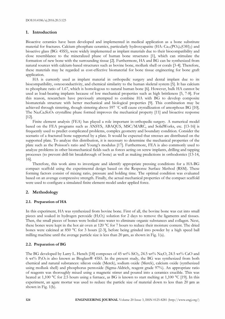
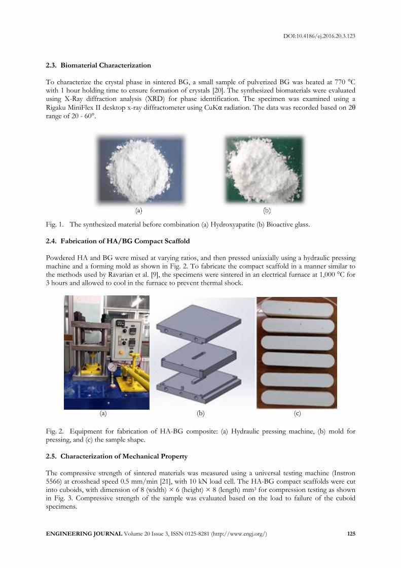
Fig. 1. The synthesized material before combination (a) Hydroxyapatite (b) Bioactive glass. 2.4. Fabrication of HA/BG Compact Scaffold Powdered HA and BG were mixed at varying ratios, and then pressed uniaxially using a hydraulic pressing machine and a forming mold as shown in Fig. 2. To fabricate the compact scaffold in a manner similar to the methods used by Ravarian et al. [9], the specimens were sintered in an electrical furnace at 1,000 °C for 3 hours and allowed to cool in the furnace to prevent thermal shock.
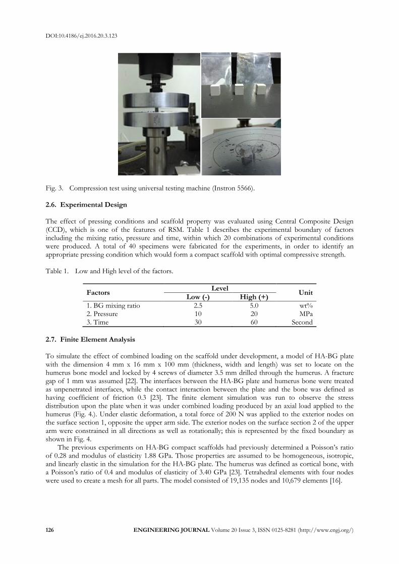
Fig. 2. Equipment for fabrication of HA-BG composite: (a) Hydraulic pressing machine, (b) mold for pressing, and (c) the sample shape. 2.5. Characterization of Mechanical Property The compressive strength of sintered materials was measured using a universal testing machine (Instron 5566) at crosshead speed 0.5 mm/min [21], with 10 kN load cell. The HA-BG compact scaffolds were cut into cuboids, with dimension of 8 (width) × 6 (height) × 8 (length) mm3 for compression testing as shown in Fig. 3. Compressive strength of the sample was evaluated based on the load to failure of the cuboid specimens.
(a) (b) (c)
DOI:10.4186/ej.2016.20.3.123
126 ENGINEERING JOURNAL Volume 20 Issue 3, ISSN 0125-8281 (http://www.engj.org/)
Fig. 3. Compression test using universal testing machine (Instron 5566). 2.6. Experimental Design The effect of pressing conditions and scaffold property was evaluated using Central Composite Design (CCD), which is one of the features of RSM. Table 1 describes the experimental boundary of factors including the mixing ratio, pressure and time, within which 20 combinations of experimental conditions were produced. A total of 40 specimens were fabricated for the experiments, in order to identify an appropriate pressing condition which would form a compact scaffold with optimal compressive strength. Table 1. Low and High level of the factors.
Factors Level
Unit Low (-) High (+)
1. BG mixing ratio 2.5 5.0 wt% 2. Pressure 10 20 MPa 3. Time 30 60 Second
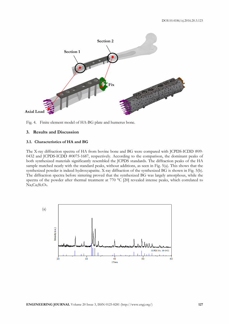
2.7. Finite Element Analysis To simulate the effect of combined loading on the scaffold under development, a model of HA-BG plate with the dimension 4 mm x 16 mm x 100 mm (thickness, width and length) was set to locate on the humerus bone model and locked by 4 screws of diameter 3.5 mm drilled through the humerus. A fracture gap of 1 mm was assumed [22]. The interfaces between the HA-BG plate and humerus bone were treated as unpenetrated interfaces, while the contact interaction between the plate and the bone was defined as having coefficient of friction 0.3 [23]. The finite element simulation was run to observe the stress distribution upon the plate when it was under combined loading produced by an axial load applied to the humerus (Fig. 4.). Under elastic deformation, a total force of 200 N was applied to the exterior nodes on the surface section 1, opposite the upper arm side. The exterior nodes on the surface section 2 of the upper arm were constrained in all directions as well as rotationally; this is represented by the fixed boundary as shown in Fig. 4.
The previous experiments on HA-BG compact scaffolds had previously determined a Poisson’s ratio of 0.28 and modulus of elasticity 1.88 GPa. Those properties are assumed to be homogeneous, isotropic, and linearly elastic in the simulation for the HA-BG plate. The humerus was defined as cortical bone, with a Poisson’s ratio of 0.4 and modulus of elasticity of 3.40 GPa [23]. Tetrahedral elements with four nodes were used to create a mesh for all parts. The model consisted of 19,135 nodes and 10,679 elements [16].
DOI:10.4186/ej.2016.20.3.123
ENGINEERING JOURNAL Volume 20 Issue 3, ISSN 0125-8281 (http://www.engj.org/) 127
Fig. 4. Finite element model of HA-BG plate and humerus bone.
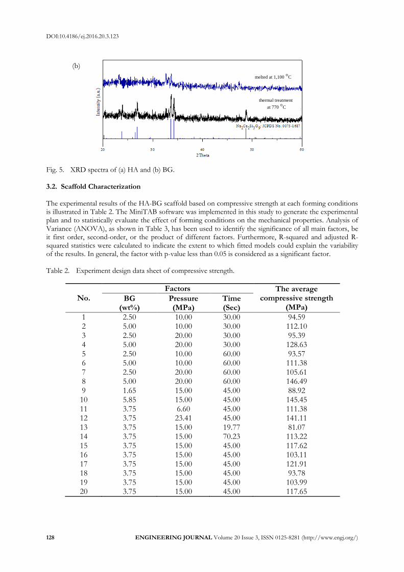
3. Results and Discussion 3.1. Characteristics of HA and BG The X-ray diffraction spectra of HA from bovine bone and BG were compared with JCPDS-ICDD #09-0432 and JCPDS-ICDD #0075-1687, respectively. According to the comparison, the dominant peaks of both synthesized materials significantly resembled the JCPDS standards. The diffraction peaks of the HA sample matched neatly with the standard peaks, without additions, as seen in Fig. 5(a). This shows that the synthesized powder is indeed hydroxyapatite. X-ray diffraction of the synthesized BG is shown in Fig. 5(b). The diffraction spectra before sintering proved that the synthesized BG was largely amorphous, while the spectra of the powder after thermal treatment at 770 °C [20] revealed intense peaks, which correlated to Na2Ca2Si3O9.
(a)
Axial Load
Fix
Section 1
Section 2
DOI:10.4186/ej.2016.20.3.123
128 ENGINEERING JOURNAL Volume 20 Issue 3, ISSN 0125-8281 (http://www.engj.org/)
Fig. 5. XRD spectra of (a) HA and (b) BG. 3.2. Scaffold Characterization The experimental results of the HA-BG scaffold based on compressive strength at each forming conditions is illustrated in Table 2. The MiniTAB software was implemented in this study to generate the experimental plan and to statistically evaluate the effect of forming conditions on the mechanical properties. Analysis of Variance (ANOVA), as shown in Table 3, has been used to identify the significance of all main factors, be it first order, second-order, or the product of different factors. Furthermore, R-squared and adjusted R-squared statistics were calculated to indicate the extent to which fitted models could explain the variability of the results. In general, the factor with p-value less than 0.05 is considered as a significant factor. Table 2. Experiment design data sheet of compressive strength.
No.
Factors The average compressive strength
(MPa) BG
(wt%) Pressure (MPa)
Time (Sec)
1 2.50 10.00 30.00 94.59 2 5.00 10.00 30.00 112.10 3 2.50 20.00 30.00 95.39 4 5.00 20.00 30.00 128.63 5 2.50 10.00 60.00 93.57 6 5.00 10.00 60.00 111.38 7 2.50 20.00 60.00 105.61 8 5.00 20.00 60.00 146.49 9 1.65 15.00 45.00 88.92 10 5.85 15.00 45.00 145.45 11 3.75 6.60 45.00 111.38 12 3.75 23.41 45.00 141.11 13 3.75 15.00 19.77 81.07 14 3.75 15.00 70.23 113.22 15 3.75 15.00 45.00 117.62 16 3.75 15.00 45.00 103.11 17 3.75 15.00 45.00 121.91 18 3.75 15.00 45.00 93.78 19 3.75 15.00 45.00 103.99 20 3.75 15.00 45.00 117.65
(b)
melted at 1,100 °C
thermal treatment
at 770 °C
DOI:10.4186/ej.2016.20.3.123
ENGINEERING JOURNAL Volume 20 Issue 3, ISSN 0125-8281 (http://www.engj.org/) 129
Table 3. Estimate regression coefficients for compression test.
Term Coef SE Coef T P-Value
Constant 109.766 2.549 43.061 0.000 BG 14.981 1.692 8.854 0.000
Pressure 8.382 1.691 4.957 0.000 Time 5.889 1.691 3.482 0.002
BG*BG 2.069 1.649 1.255 0.219 Pressure*Pressure 5.267 1.646 3.200 0.003
Time*Time -5.018 1.646 -3.049 0.005 BG*Pressure 4.852 2.21 2.196 0.036
BG*Time 0.993 2.21 0.449 0.656 Pressure*Time 3.728 2.21 1.687 0.102
R-squared = 82.97% R-squared (adj) = 77.87%,
According to this analysis, the factors affecting the compression strength of the composite scaffold
were the mixing ratio, pressure and holding time, as well as the square of pressure and time and the interaction term between BG ratio and pressure. Thus, the regression model of scaffold compressive strength (Y) can be described as
( ) (1)
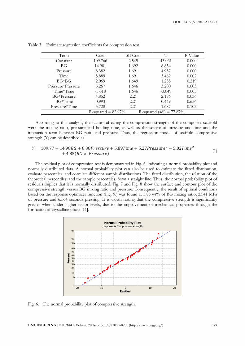
The residual plot of compression test is demonstrated in Fig. 6, indicating a normal probability plot and
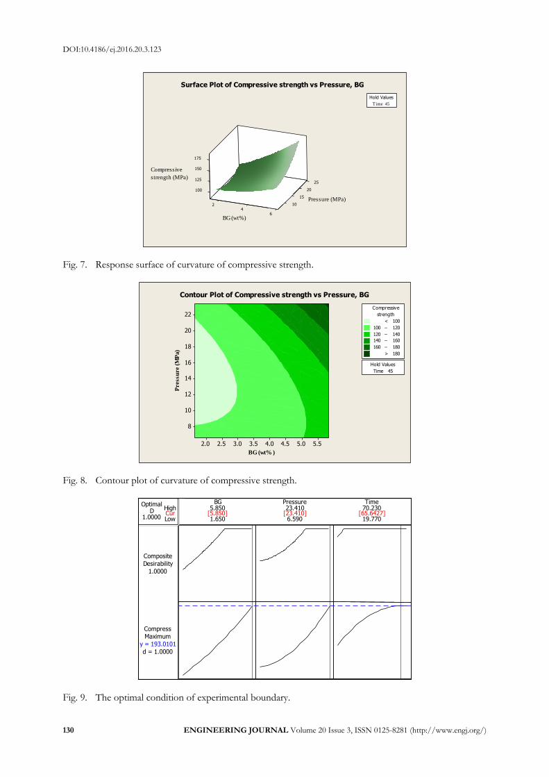
normally distributed data. A normal probability plot can also be used to estimate the fitted distribution, evaluate percentiles, and correlate different sample distributions. The fitted distribution, the relation of the theoretical percentiles, and the sample percentiles, form a straight line. Thus, the normal probability plot of residuals implies that it is normally distributed. Fig. 7 and Fig. 8 show the surface and contour plot of the compressive strength versus BG mixing ratio and pressure. Consequently, the result of optimal conditions based on the response optimizer function (Fig. 9.) was found at 5.85 wt% of BG mixing ratio, 23.41 MPa of pressure and 65.64 seconds pressing. It is worth noting that the compressive strength is significantly greater when under higher factor levels, due to the improvement of mechanical properties through the formation of crystalline phase [11].
20100-10-20
99
95
90
80
70
60
50
40
30
20
10
5
1
Residual
Pe
rce
nt
Normal Probability Plot(response is Compressive strength)
Fig. 6. The normal probability plot of compressive strength.
DOI:10.4186/ej.2016.20.3.123
130 ENGINEERING JOURNAL Volume 20 Issue 3, ISSN 0125-8281 (http://www.engj.org/)
25
20100
15
125
150
175
2 10
46
Time 45
Hold Values
Surface Plot of Compressive strength vs Pressure, BG
strength (MPa)
Compressive
BG (wt%)
Pressure (MPa)
Fig. 7. Response surface of curvature of compressive strength.
BG (wt% )
Pressu
re (
MP
a)
5.55.04.54.03.53.02.52.0
22
20
18
16
14
12
10
8
Time 45
Hold Values
>
–
–
–
–
< 100
100 120
120 140
140 160
160 180
180
strength
Compressive
Contour Plot of Compressive strength vs Pressure, BG
Fig. 8. Contour plot of curvature of compressive strength.
Fig. 9. The optimal condition of experimental boundary.
CurHigh
Low1.0000D
Optimal
d = 1.0000
Maximum
Compress
y = 193.0101
1.0000
Desirability
Composite
19.770
70.230
6.590
23.410
1.650
5.850Pressure TimeBG
[5.850] [23.410] [65.6427]
DOI:10.4186/ej.2016.20.3.123
ENGINEERING JOURNAL Volume 20 Issue 3, ISSN 0125-8281 (http://www.engj.org/) 131
According to the experimental analysis results, the HA-BG specimens which underwent compression
at the lower boundary conditions had lower mechanical properties, while the higher boundary conditions produced scaffolds of better mechanical properties. Moreover, the compressive strength and bending strength achieved in this study are superior to that of another study [21] and meets the minimum requirement of cortical bone, as shown in Table 4. It will be necessary to further investigate biological properties to confirm the biocompatibility of the compact scaffold as well as the biodegradability of the bone substitute, in order to make comparisons of the recovery rate or the regeneration rate of new bone growth. Furthermore, in vivo study will be required prior to implementation in patients. Table 4. Compressive strength values for bovine hydroxyapatite and human bone.
Type Compressive strength (MPa)
Bovine Hydroxyapatite [18] (Sintering temperature: 1,000 – 1,300 °C)
Compressive strength 12 - 65 Cortical bone [23]
Compressive strength 340 The previous study [21]
Hydroxyapatite (HA) 64 ± 18 HA+ 1.0 wt% Bioglass®45S5 26 ± 2 HA+ 2.5 wt% Bioglass®45S5 34 ± 5 HA+ 5.0 wt% Bioglass®45S5 79 ± 15 HA+ 10.0 wt% Bioglass®45S5 74 ± 8 HA+ 25.0 wt% Bioglass®45S5 131 ± 14
In this study HA+5.85 wt% Bioglass®45S5 136.92
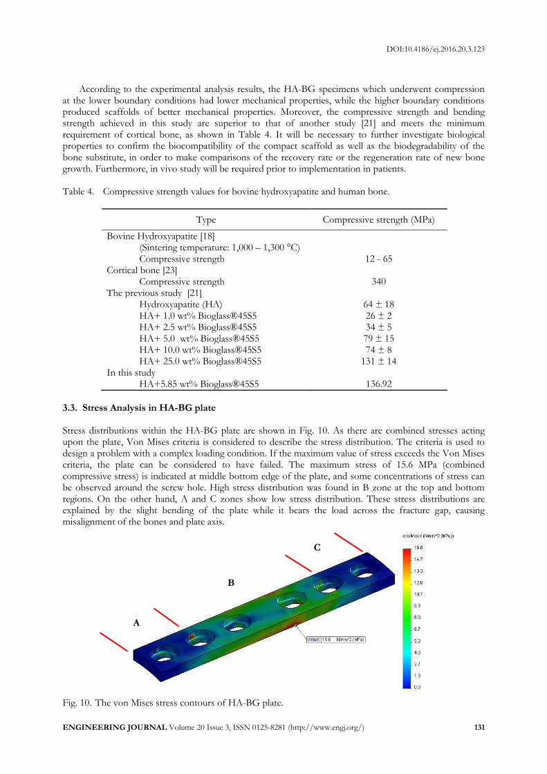
3.3. Stress Analysis in HA-BG plate Stress distributions within the HA-BG plate are shown in Fig. 10. As there are combined stresses acting upon the plate, Von Mises criteria is considered to describe the stress distribution. The criteria is used to design a problem with a complex loading condition. If the maximum value of stress exceeds the Von Mises criteria, the plate can be considered to have failed. The maximum stress of 15.6 MPa (combined compressive stress) is indicated at middle bottom edge of the plate, and some concentrations of stress can be observed around the screw hole. High stress distribution was found in B zone at the top and bottom regions. On the other hand, A and C zones show low stress distribution. These stress distributions are explained by the slight bending of the plate while it bears the load across the fracture gap, causing misalignment of the bones and plate axis.
Fig. 10. The von Mises stress contours of HA-BG plate.
A
C
B
DOI:10.4186/ej.2016.20.3.123
132 ENGINEERING JOURNAL Volume 20 Issue 3, ISSN 0125-8281 (http://www.engj.org/)
4. Conclusion In this study, the effects of forming conditions on scaffold’s compressive strength were evaluated based on CCD experimental design. The results revealed that all forming conditions have a significant effect on the mechanical properties of the composite scaffolds. The optimal condition was found at 5.85 wt% of BG mixing ratio, 23.41 MPa of pressure and 65.64 seconds of holding time, leading to the optimal compressive strength of 136.92 MPa. The optimal condition may be explained through the formation of a crystalline phase which strengthens the material. In addition, the simulation based on the axial load of 200 N applied to the bone resulted in a predicted maximum compressive stress of 15.6 MPa at the plate (combined compressive stress by axial and bending stresses). The simulated stress using FEA was compared with the testing compressive strength of HA-BG (136.92 MPa). Therefore, according to this simulation, the HA-BG scaffold can be applied safely as an implant. Further investigation on biological properties of the HA-BG compact scaffold is on-going to develop prototypes for clinical use in the near future.
Acknowledgement The authors are grateful to Chiang Mai University for financial support, as well as, Department of Industrial Engineering and Biomedical Engineering Center, Faculty of Engineering, Chiang Mai University for their facility support and Department of Tools and Die Engineering and Machine Tool Technology, Rajamangala University of Technology Lanna (RMUTL) for technical support.
References [1] D. Bellucci, A. Sola, M. Gazzarri, F. Chiellini and V. Cannillo, “A new hydroxyapatite-based
biocomposite for bone replacement,” Materials Science and Engineering: C, vol. 33, no. 3, pp. 1091-1101, 2013.
[2] D. Bellucci, A. Sola and V. Cannillo, “Bioactive glass-based composites for the production of dense sintered bodies and porous scaffolds,” Materials Science and Engineering: C, vol. 33, no. 4, pp. 2138-2151, 2013.
[3] W. Wattanutchariya and P. Yenbut, “Characterization of phosphate glass/Hydroxyapatite scaffold for palate repair,” Advance Materials Research, vol. 931-932, pp. 301-305, 2014.
[4] W. Wattanutchariya and W. Changkowchai, “Characterization of porous scaffold from chitosan-gelatin/hydroxyapatite for bone grafting,” Lecture Notes in Engineering and Computer Science, vol. 2210, pp. 1073-1077, 2014.
[5] W. Que, K. A. Khor, J. L. Xu, and L. G. Yu, “Hydroxyapatite/titaniananocomposites derived by combining high-energy ball milling with spark plasma sintering processes,” Journal of the European Ceramic Society, vol. 28, no. 16, pp. 3083-3090, 2008.
[6] Y. W. Gu, N. H. Loh, K. A. Khor, S. B. Tor, and P. Cheang, “Spark plasma sintering of hydroxyapatite powders,” Biomaterials, vol. 23, no. 1, pp. 37-43, 2002.
[7] H. B. Guo, X. Miao, Y. Chen, P. Cheang, and K. A. Khor, “Characterization of hydroxyapatite and bioglass 316L fibre composites prepared by spark plasma sintering,” Materials Letters, vol. 58, no. 3, pp. 304-307, 2004.
[8] F. N. Oktar and G. Goller, “Sintering effects on mechanical properties of glass-reinforced hydroxyapatite composites,” Ceramics International, vol. 28, no. 6, pp. 617-621, 2002.
[9] R. Ravarian, F. Moztarzadeh, M. S. Hashjin, S. M. Rabiee, P. Khoshakhlagh, and M. Tahriri, “Synthesis, characterization and bioactivity investigation of bioglass/hydroxyapatite composite,” Ceramics International, vol. 36, no. 1, pp. 291-297, 2010.
[10] D. C. Clupper and L.L. Hench, “Crystallization kinetics of tape cast bioactive glass 45S5,” Journal of Non-Crystalline Solids, vol. 318, no. 1, pp. 43-48, 2003.
[11] Q. Z. Chen, J. L. Xu, L. G. Yu, X. Y. Fang, and K. A. Khor, “Spark plasma sintering of sol-gel derived 45S5 Bioglass®-ceramics: Mechanical properties and biocompatibility evaluation,” Materials Science and Engineering C, vol. 32, no. 3, pp. 494-502, 2012.
DOI:10.4186/ej.2016.20.3.123
ENGINEERING JOURNAL Volume 20 Issue 3, ISSN 0125-8281 (http://www.engj.org/) 133
[12] D. C. Clupper, J. J. Mecholsky Jr, G. P. LaTorre, and D. C. Greenspan, “Bioactivity of tape cast and sintered bioactive glass-ceramic in simulated body fluid,” Biomaterials, vol. 23, no. 12, pp. 2599-2606, 2002.
[13] W. A. Lughmani, K. B. Marouf, and I. Ashcroft, “Drilling in cortical bone: A finite element model and experimental investigations,” Journal of the Mechanical Behavior of Biomedical Materials, vol. 42, pp. 32-42, 2015.
[14] C. K. Chao, C. C. Hsu, J. L. Wang, and J. Lin, “Increasing bending strength of tibial locking screws: Mechanical tests and finite element analyses,” Clinical Biomechanics, vol. 22, no. 1, pp. 59-66, 2007.
[15] C. M. E. Avery, P. Bujtár, J. Simonovics, T. Dézsi, K. Váradi, G. K. B. Sándor, and J. Pan, “A finite element analysis of bone plates available for prophylactic internal fixation of the radial osteocutaneous donor site using the sheep tibia model,” Medical Engineering & Physics, vol. 35, no. 10, pp. 1421-1430, 2013.
[16] T. Fongsamootr and P. Suttakul, “Effect of periodontal ligament on stress distribution and displacement of tooth and bone structure using finite element simulation,” Engineering Journal, vol. 19, no. 2, pp. 99-108, 2015.
[17] M. Moazen, A. C. Jones, A. Leonidou, Z. Jin, R. K. Wilcox, and E. Tsiridis, “Rigid versus flexible plate fixation for periprosthetic femoral fracture—Computer modelling of a clinical case,” Medical Engineering & Physics, vol. 34, no. 8, pp. 1041-1048, 2012.
[18] L. L. Hench and J. Wilson, An Introduction to Bioceramics. London: World Scientific, 1993. [19] X. Chatzistavrou, T. Zorba, E. Kontonasaki, K. Chrissafis, and P. Koidis, “Following bioactive glass
behaviour beyond melting temperature by thermal and optical methods,” Physica Status Solidi (a), vol. 201, no. 5, pp. 944-951, 2004.
[20] M. Plewinski, K. Schickle, M. Lindner, A. Kirsten, M. Weber, and H. Fischer, “The effect of crystallization of bioactive bioglass 45S5 on apatite formation and degradation,” Dental Materials, vol. 29, no. 12, pp. 1256-1264, 2013.
[21] H. Demirkiran, A. Mohandas, M. Dohi, and A. Fuentes, “Bioactivity and mineralization of hydroxyapatite with bioglass as sintering aid and bioceramics with Na3Ca6(PO4)5 and Ca5(PO4)2SiO4 in a silicate matrix,” Materials Science and Engineering: C, vol. 30, no. 2, pp. 263-272, 2010.
[22] M. Nassiri, B. MacDonald, and J. M. O’Byrne, “Computational modeling of long bone fractures fixed with locking plates—How can the risk of implant failure be reduced?,” Journal of Orthopaedics, vol. 10, no. 1, pp. 29-37, 2013.
[23] S. Sabalic, J. Kodvanj, and A. Pavic, “Comparative study of three models of extra-articular distal humerus fracture osteosynthesis using the finite element method on an osteoporotic computational model,” Injury, International Journal of Care of the Injured, vol. 44, no. S3, pp. S56-S61, 2013.