Embed Size (px)
Citation preview
Approaches to building single-stage AC/AC conversion switch-mode audio poweramplifiers
Petar Ljusev and Michael A.E. AndersenØrsted • DTU, Automation, Technical University of Denmark
Elektrovej, DTU Building 325, DK-2800 Kgs. Lyngby, DenmarkE-mail: [email protected], [email protected]
Abstract - This paper discusses the possible topologiesand promising approaches towards direct single-phase AC-ACconversion of the mains voltage for audio applications. Whencompared to standard Class-D switching audio power amplifierswith a separate power supply, it is expected that direct conversionwill provide better efficiency and higher level of integration,leading to lower component count, volume and cost, but at theexpense of a minor performance deterioration.
I. INTRODUCTION
Switching-mode Class D audio amplifiers are becom-ing increasingly popular, as more and more commercialproducts with appealing performance in terms of effi-ciency and audio quality are emerging on the market. Thisbreakthrough of the modern power electronics hi-tech wasmade available by both advancements of power switchingtechnology and improved signal processing. However, itsdevelopment is far from being over, as ever increasingnumber of engineers is trying to address the special needs,improvements or simple cost reduction requested by thecustomers.
In the past, the field of audio conversion was solelyleft to the linear audio amplifiers in classes A and B,their improved hybrid AB, as well as complex B2 andG. Their extraordinary performance, low total harmonicdistortion + noise (THD+N) levels and simple controltechniques overshadowed the obvious drawbacks of poorefficiency, huge power losses, voluminous heat sinks andsubsequently high price. The switching approach (ex. ClassD) in audio technology and acoustics seemed like cursed,since its inevitable nonlinearity, introduction of time delays(rise, fall and dead times), need for output low-pass filter,switching frequency limiting the control bandwidth as wellas the EMC problems made it less preferable choice.However, introduction of advanced control techniques [1]to compensate for the nonlinearities in the modulation andsubsequent amplification phase has even led to severalcommercially available products. These products featureextraordinary high efficiency, low dissipation at full powerand at idle, leading to smaller heat sinks, less weight, betterintegration and thus smaller packages. Due to this, powersupply nominal rating can be reduced, yielding cheaperfinal products. Even more, their THD+N is becomingcomparable with some of the high-end linear audio poweramplifiers.
In the switching audio amplifiers (Class D) the powerswitches, which are usually MOSFETs, are used to connectthe full DC voltage with a certain polarity across thecombination of a filter and a loudspeaker, as decided by the
control algorithm. Therefore, much of the performance ofthese switching audio amplifiers depends upon the qualityand stiffness of the DC bus voltage, thus often necessitatingthe usage of bulky linear stabilized DC supplies or switchmode power supplies (SMPSs). On the other hand, thisleads to lower power efficiency and higher cost of the finalaudio appliance. Power supply rejection ratio (PSRR) canbe greatly improved by introduction of different linear andnonlinear control methods, but this results in substantialincrease in control complexity.
SIngle Conversion stage AMplifier (SICAM) is a newparadigm in the audio power amplifier technology, and thenext important step in designing switching audio amplifiers.It is intended for the next generation of light, highlyefficient and cheap audio appliances with satisfactory audioperformance. It is also quite appealing for the Active Trans-ducer (AT) [2] approach for direct conversion of the mainspower into acoustic output in one simplified topologicalstage, like in the active loudspeaker systems and dedicatedsubwoofer units. Its unique structure and control principlesshould provide energy efficiency beyond the levels of theconventional compound of a Class D audio amplifier and apower supply, by closely interconnecting the power supplystage and the subsequent audio power amplification stage(multiplexing the functions of the active switches has beenalready seen in many single stage power factor correc-tion topologies). By reshaping the audio conversion chainthrough dedication and integration, the power supply willnot strive for complex rectifying schemes and topologiesanymore. Lowering the demands against the power supplywill inevitably impose some trade-offs in the level of controlcomplexity, modulation methods and performance of theaudio amplifier. Notwithstanding, the new direct topologiesand the improved control methods will introduce higherenergy efficiency, since large part of the power losses aregenerated in the power supply as a result of the numerousinternal electrical energy conversions. Last but not least,SICAM is intended for a segment of the consumer marketwhich is cost driven, so its low component count and lowcost represent a significant benefit.
This paper aims to present the entire brainstormingphase performed at the SICAM project start, where all theideas were described in general terms. After discussing thechallenges and limitations that were faced at the very be-ginning, the paper will focus on one possible classificationof the SICAM topologies. The paper will also present someinteresting investigation results as well as identify the mostpromising topologies.
J.nr.: SICAM.01.05.007
II. SICAM INTERNAL STRUCTURE ANDPROPOSED TOPOLOGIES
SICAM is intended for single-phase connection to theAC mains and this has proven until now as the most severelimitation towards building an audio amplifier into a singleconversion stage.
This conclusion has a logical and mathematically ex-plainable reason. The instantaneous power p(t) can befound as a product of the instantaneous voltage u(t) andinstantaneous current i(t):
p(t) = u(t)i(t) (1)
where AC-mains voltage has the form of a sinusoidalfunction u(t) = Umsin(ωt). From above equations it isobvious that, at instants where mains voltage equals zero(t = nπ where n is an integer), i.e. at zero-crossingsthere is no energy transferred to the load (unless the inputcurrent is infinite i(t) → ∞, which is certainly not aviable assumption). Moreover, the rate at which electricalgrid supplies energy to the load is greatly reduced andperformance is inevitably compromised in some vicinityof the zero-crossing points.
In the processes where dynamics is determined by timeconstants and responses on a larger time scale than the inputvoltage zero-crossing occurrence (ex. electroheat processes,slowly rotating electrical motors powered by cycloconvert-ers), the performance doesn’t suffer much, since the loadresponds to the voltage effective or average value. Audioconversion, on the other hand, is certainly not this case sincehigh-fidelity reproduction in the audio band up to 20 kHzis compulsory.
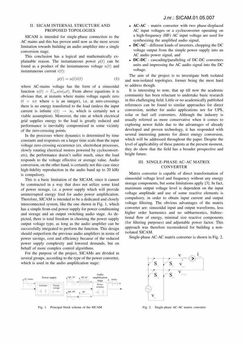
This is a basic limitation of the SICAM, since it cannotbe constructed in a way that does not utilize some kindof power storage, i.e. a power supply which will provideuninterrupted energy feed for audio power amplification.Therefore, SICAM is intended to be a dedicated and closelyinterconnected system, like the one shown in Fig. 1, whichhas a simple front-end power supply for power conditioningand storage and an output switching audio stage. As de-picted, there is total freedom in choosing the power supplyoutput voltage type, as long as the audio amplifier can besuccessfully integrated to perform the function. This designshould outperform the previous audio amplifiers in terms ofpower savings, cost and efficiency because of the reducedpower supply complexity and lowered demands, but onbehalf of more complex control algorithms.
For the purpose of the project, SICAMs are divided inseveral groups, according to the type of the power converter,which is used in the audio amplification stage:
Fig. 1. Principal block scheme of the SICAM
• AC-AC - matrix converter with two phase-displacedAC input voltages or a cycloconverter operating ona high-frequency (HF) AC input voltage are used forsynthesizing the amplified audio signal,
• DC-AC - different kinds of inverters, chopping the DCvoltage output from the simple power supply into anAC audio power signal, and
• DC-DC - cascading/paralleling of DC-DC convertersunits and impressing the AC audio signal into the DCvoltage.
The aim of the project is to investigate both isolatedand non-isolated topologies, former being the most hardto address though.
It is interesting to note, that up till now the academiccommunity has been reluctant to undertake basic researchin this challenging field. Little or no academically publishedreferences can be found to similar approaches for directconversion, neither for audio applications nor for UPS,solar or fuel cell converters. Although the industry isusually referred as more conservative when it comes toexploring newer fields due to the advantages of alreadydeveloped and proven technology, it has responded withseveral interesting patents for direct energy conversion,which will be addressed throughout the paper. Despite thelevel of applicability of these patents at the present moment,they do show that the field has a broader prospective andbright future.
III. SINGLE-PHASE AC-AC MATRIXCONVERTER
Matrix converter is capable of direct transformation ofsinusoidal voltage level and frequency without any energystorage components, but some limitations apply [3]. In fact,maximum output voltage level is dependent on the inputvoltage amplitude and use of some reactive elements iscompulsory, in order to obtain input current and outputvoltage filtering. The obvious advantages of the matrixconverter are: sinusoidal input and output waveforms, lesshigher order harmonics and no subharmonics, bidirec-tional flow of energy, minimal size reactive components(for filtering purposes) and adjustable power factor. Thisapproach was therefore reconsidered for building a non-isolated SICAM.
Single-phase AC-AC matrix converter is shown in Fig. 2.
Fig. 2. Single-phase AC-AC matrix converter
J.nr.: SICAM.01.05.007
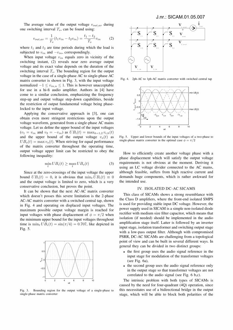
The average value of the output voltage vout,av duringone switching interval Ts, can be found using:
vout,av =1
Ts
(t1vin − t2vin) =t1 − t2
Ts
vin (2)
where t1 and t2 are time periods during which the load issubjected to vin and −vin, correspondingly.
When input voltage vin equals zero in vicinity of theswitching instant, (2) reveals near zero average outputvoltage and its exact value depends on the duration of theswitching interval Ts. The bounding region for the outputvoltage in the case of a single-phase AC to single-phase ACmatrix converter is shown in Fig. 3, with the input voltagenormalized −1 ≤ vin,n ≤ 1. This is however unacceptablefor use in a hi-fi audio amplifier. Authors in [4] havecome to a similar conclusion, emphasizing the frequencystep-up and output voltage step-down capabilities, besidethe restriction of output fundamental voltage being phase-locked to the input voltage.
Applying the conservative approach in [3], one canobtain even more stringent restrictions upon the outputvoltage waveform, generated from a single-phase AC mainsvoltage. Let us define the upper bound of the input voltages(v1 = vin and v2 = −vin) as UBi(t) = maxh=1,2 vi,h(t)and the upper bound of the output voltage vo(t) asUBo(t) = max vo(t). When striving for equal performanceof the matrix converter throughout the operating time,output voltage upper limit can be restricted to obey thefollowing inequality:
mint
UBi(t) ≥ maxt
UBo(t) (3)
Since at the zero-crossings of the input voltage the upperbound UBi(t) = 0, it is obvious that mint UBi(t) ≡ 0and the output voltage is limited to zero, which is a veryconservative conclusion, but proves the point.
It can be shown that the next AC-AC matrix converterwhich doesn’t posses this severe limitation is the 2-phaseAC-AC matrix converter with a switched central tap, shownin Fig. 4 and operating on displaced input voltages. Themaximum possible output voltage margin is reached forinput voltages with phase displacement of φ = π/2 whenthe minimum upper bound for the input voltages throughouttime is mint UBi(t) = sin(π/4) = 0.707, like depicted inFig. 5.
0 2 4 6 8 10
−1
−0.5
0
0.5
1
ωt
v in,n
Fig. 3. Bounding region for the output voltage of a single-phase tosingle-phase matrix converter
Fig. 4. 2ph-AC to 1ph-AC matrix converter with switched central tap
0 2 4 6 8 10−2
−1.5
−1
−0.5
0
0.5
1
ωt
v 1,in
,n, v
2,in
,n
min UBi(t)
max LBi(t)
π/4 π/2
v1,in
v2,in
−v1,in
−v2,in
Fig. 5. Upper and lower bounds of the input voltages of a two-phase tosingle-phase matrix converter in the optimal case φ = π/2
How to efficiently create another voltage phase with aphase displacement which will satisfy the output voltagerequirements is not obvious at the moment. Deriving itusing an LC voltage divider connected to the AC mains,although feasible, suffers from high reactive current anddemands huge components, which is rather awkward forthe intended use.
IV. ISOLATED DC-AC SICAMS
This class of SICAMs shows a strong resemblance withthe Class D amplifiers, where the front-end isolated SMPSis used for providing stable input DC voltage. However, thepower supply used in SICAM is a simple non-isolated dioderectifier with medium size filter capacitor, which means thatisolation (if needed) should be implemented in the audioamplification stage itself. Latter is followed by an inverterinput stage, isolation transformer and switching output stagewith a low-pass output filter. Although with compromisedPSRR, DC-AC SICAMs are challenging from a topologicalpoint of view and can be built in several different ways. Ingeneral they can be divided in two distinct groups:
• the first group uses the audio signal reference in theinput stage for modulation of the transformer voltages(see Fig. 6a),
• the second group uses the audio signal reference onlyin the output stage so that transformer voltages are notcorrelated to the audio signal (see Fig. 6 b,c).
The intrinsic problem with both types of SICAMs iscaused by the need for four-quadrant (4Q) operation, sincethis necessitates use of a bidirectional bridge in the outputstage, which will be able to block both polarities of the
J.nr.: SICAM.01.05.007
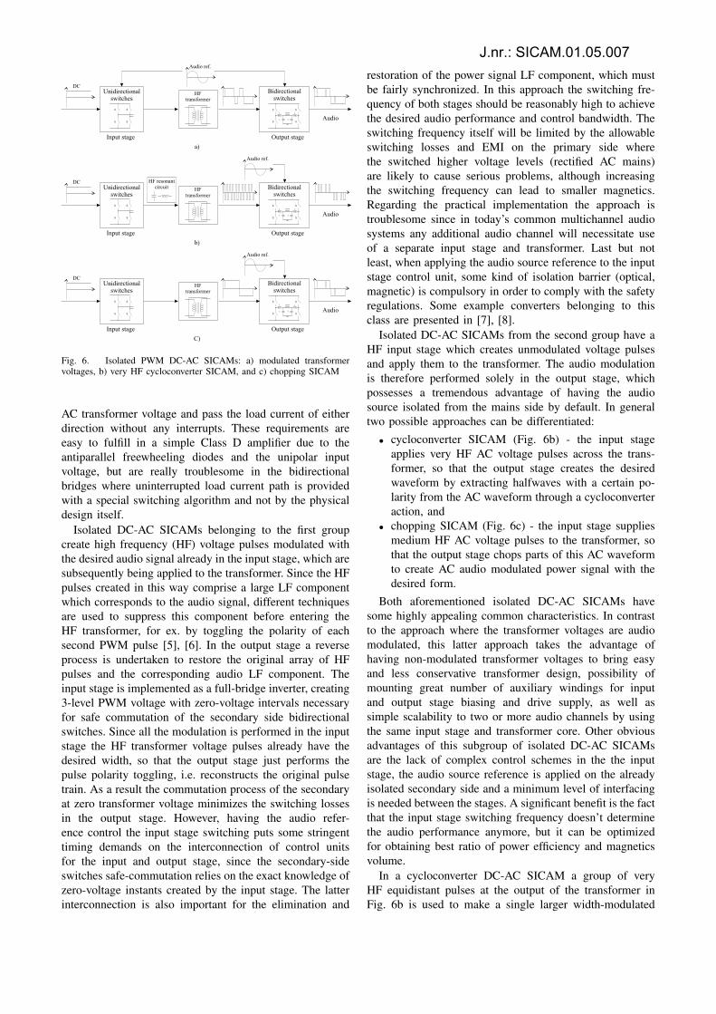
Fig. 6. Isolated PWM DC-AC SICAMs: a) modulated transformervoltages, b) very HF cycloconverter SICAM, and c) chopping SICAM
AC transformer voltage and pass the load current of eitherdirection without any interrupts. These requirements areeasy to fulfill in a simple Class D amplifier due to theantiparallel freewheeling diodes and the unipolar inputvoltage, but are really troublesome in the bidirectionalbridges where uninterrupted load current path is providedwith a special switching algorithm and not by the physicaldesign itself.
Isolated DC-AC SICAMs belonging to the first groupcreate high frequency (HF) voltage pulses modulated withthe desired audio signal already in the input stage, which aresubsequently being applied to the transformer. Since the HFpulses created in this way comprise a large LF componentwhich corresponds to the audio signal, different techniquesare used to suppress this component before entering theHF transformer, for ex. by toggling the polarity of eachsecond PWM pulse [5], [6]. In the output stage a reverseprocess is undertaken to restore the original array of HFpulses and the corresponding audio LF component. Theinput stage is implemented as a full-bridge inverter, creating3-level PWM voltage with zero-voltage intervals necessaryfor safe commutation of the secondary side bidirectionalswitches. Since all the modulation is performed in the inputstage the HF transformer voltage pulses already have thedesired width, so that the output stage just performs thepulse polarity toggling, i.e. reconstructs the original pulsetrain. As a result the commutation process of the secondaryat zero transformer voltage minimizes the switching lossesin the output stage. However, having the audio refer-ence control the input stage switching puts some stringenttiming demands on the interconnection of control unitsfor the input and output stage, since the secondary-sideswitches safe-commutation relies on the exact knowledge ofzero-voltage instants created by the input stage. The latterinterconnection is also important for the elimination and
restoration of the power signal LF component, which mustbe fairly synchronized. In this approach the switching fre-quency of both stages should be reasonably high to achievethe desired audio performance and control bandwidth. Theswitching frequency itself will be limited by the allowableswitching losses and EMI on the primary side wherethe switched higher voltage levels (rectified AC mains)are likely to cause serious problems, although increasingthe switching frequency can lead to smaller magnetics.Regarding the practical implementation the approach istroublesome since in today’s common multichannel audiosystems any additional audio channel will necessitate useof a separate input stage and transformer. Last but notleast, when applying the audio source reference to the inputstage control unit, some kind of isolation barrier (optical,magnetic) is compulsory in order to comply with the safetyregulations. Some example converters belonging to thisclass are presented in [7], [8].
Isolated DC-AC SICAMs from the second group have aHF input stage which creates unmodulated voltage pulsesand apply them to the transformer. The audio modulationis therefore performed solely in the output stage, whichpossesses a tremendous advantage of having the audiosource isolated from the mains side by default. In generaltwo possible approaches can be differentiated:
• cycloconverter SICAM (Fig. 6b) - the input stageapplies very HF AC voltage pulses across the trans-former, so that the output stage creates the desiredwaveform by extracting halfwaves with a certain po-larity from the AC waveform through a cycloconverteraction, and
• chopping SICAM (Fig. 6c) - the input stage suppliesmedium HF AC voltage pulses to the transformer, sothat the output stage chops parts of this AC waveformto create AC audio modulated power signal with thedesired form.
Both aforementioned isolated DC-AC SICAMs havesome highly appealing common characteristics. In contrastto the approach where the transformer voltages are audiomodulated, this latter approach takes the advantage ofhaving non-modulated transformer voltages to bring easyand less conservative transformer design, possibility ofmounting great number of auxiliary windings for inputand output stage biasing and drive supply, as well assimple scalability to two or more audio channels by usingthe same input stage and transformer core. Other obviousadvantages of this subgroup of isolated DC-AC SICAMsare the lack of complex control schemes in the the inputstage, the audio source reference is applied on the alreadyisolated secondary side and a minimum level of interfacingis needed between the stages. A significant benefit is the factthat the input stage switching frequency doesn’t determinethe audio performance anymore, but it can be optimizedfor obtaining best ratio of power efficiency and magneticsvolume.
In a cycloconverter DC-AC SICAM a group of veryHF equidistant pulses at the output of the transformer inFig. 6b is used to make a single larger width-modulated
J.nr.: SICAM.01.05.007
pulse according to the audio reference and the modulatoroutput. This principle can be therefore referred as pulsedensity modulation (PDM). Although each of the HF pulsesin the input stage can have a rectangular form with the samewidth, some resonant converters working with frequenciesin the MHz range can be used for producing pulses withsinusoidal shape. Resonant converters are however notfavored, since their control usually depends on variablefrequency operation and the output impedance is relativelyhigh, which is not adequate for an audio amplifier drivinga low impedance reactive load. In the same time, higherfrequency of the voltage pulses allows for even smaller HFtransformer. Increasing the switching frequency on the otherhand inevitably increases the eddy current and proximitylosses in the magnetics and the converter switching losses,so that the use of different techniques for reducing thelatter, like for example zero voltage switching (ZVS) PWMinverters as a derivation of the HF ZVSPWM rectifiers[9] should be reconsidered. It should be emphasized thatdepending on the implementation and the topology, thereduction of the switching losses may be feasible or not,depending predominantly on the allowed audio performancedeterioration from the intentionally inserted delay times forallowing no-loss charging and discharging of the parasiticoutput capacitances of the switches.
The chopping DC-AC SICAM in Fig. 6c has an inputstage with a lower switching frequency, when compared tothe cycloconverter SICAM. The rectangular voltage on thetransformer secondary is chopped on the secondary side bya bidirectional bridge to bring the correct PWM output volt-age across the combination of output filter and loudspeaker.Although with increased size of the transformer, the chop-ping DC-AC SICAMs are likely to operate more reliablyand run cooler than the cycloconverter DC-AC, since thefrequency dependent magnetics losses and the switchinglosses which tend to be very high at rectified mains voltagelevels will be decreased. A possible implementation of thechopping DC-AC SICAM is shown in [10]. This class ofisolated DC-AC SICAMs has been investigated in moredetail during the project work and a master/slave isolatedDC-AC SICAM has been realized and reported [11].
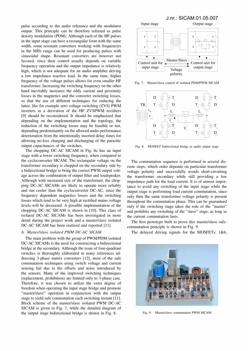
A. Master/slave isolated PWM DC-AC SICAMThe main problem with the group of PWM/PDM isolated
DC-AC SICAMs is the need for constructing a bidirectionalbridge at the secondary. Although the issue of four-quadrantswitches is thoroughly elaborated in many references ad-dressing 3-phase matrix converters [12], most of the safecommutation techniques using switch voltage and currentsensing fail due to the offsets and noise introduced bythe sensors. Many of the improved switching techniques(replacement, prohibition) are limited only to 3-phase case.Therefore, it was chosen to utilize the extra degree offreedom when operating the input stage bridge and promote”master/slave” operation in conjunction with the outputstage to yield safe commutation each switching instant [11].Block scheme of the master/slave isolated PWM DC-ACSICAM is given in Fig. 7, while the detailed diagram ofthe output stage bidirectional bridge is shown in Fig. 8.
Fig. 7. Master/slave control of isolated PDM/PWM SICAM
Fig. 8. MOSFET bidirectional bridge as audio output stage
The commutation sequence is performed in several dis-crete steps, which order depends on particular transformervoltage polarity and successfully avoids short-circuitingthe transformer secondary while still providing a lowimpedance path for the load current. It is of utmost impor-tance to avoid any switching of the input stage while theoutput stage is performing load current commutation, sinceonly then the same transformer voltage polarity is presentthroughout the commutation phase. This can be guaranteedonly if the switching stage takes the role of the ”master”and prohibits any switching of the ”slave” stage, as long asthe current commutation lasts.
The first prototype built to prove this master/slave safe-commutation principle is shown in Fig. 9.
The delayed driving signals for the MOSFETs: 1&6,
Fig. 9. Master/slave commutation PWM SICAM
J.nr.: SICAM.01.05.007
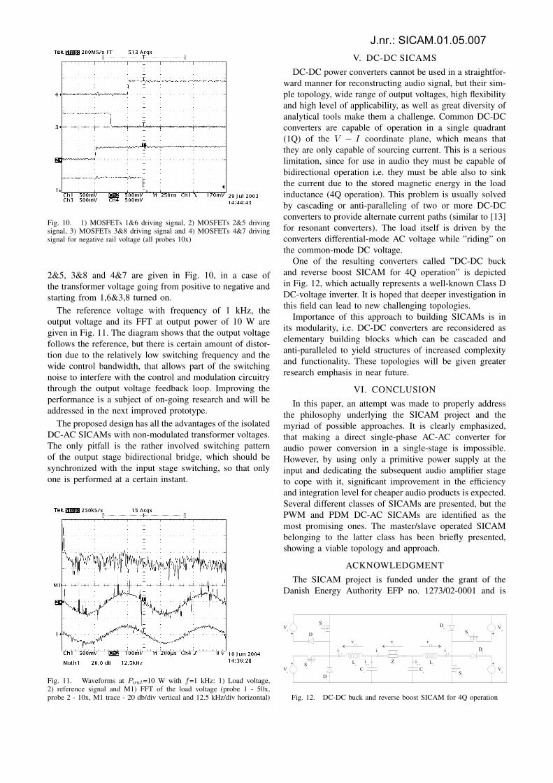
Fig. 10. 1) MOSFETs 1&6 driving signal, 2) MOSFETs 2&5 drivingsignal, 3) MOSFETs 3&8 driving signal and 4) MOSFETs 4&7 drivingsignal for negative rail voltage (all probes 10x)
2&5, 3&8 and 4&7 are given in Fig. 10, in a case ofthe transformer voltage going from positive to negative andstarting from 1,6&3,8 turned on.
The reference voltage with frequency of 1 kHz, theoutput voltage and its FFT at output power of 10 W aregiven in Fig. 11. The diagram shows that the output voltagefollows the reference, but there is certain amount of distor-tion due to the relatively low switching frequency and thewide control bandwidth, that allows part of the switchingnoise to interfere with the control and modulation circuitrythrough the output voltage feedback loop. Improving theperformance is a subject of on-going research and will beaddressed in the next improved prototype.
The proposed design has all the advantages of the isolatedDC-AC SICAMs with non-modulated transformer voltages.The only pitfall is the rather involved switching patternof the output stage bidirectional bridge, which should besynchronized with the input stage switching, so that onlyone is performed at a certain instant.
Fig. 11. Waveforms at Pout=10 W with f=1 kHz: 1) Load voltage,2) reference signal and M1) FFT of the load voltage (probe 1 - 50x,probe 2 - 10x, M1 trace - 20 db/div vertical and 12.5 kHz/div horizontal)
V. DC-DC SICAMS
DC-DC power converters cannot be used in a straightfor-ward manner for reconstructing audio signal, but their sim-ple topology, wide range of output voltages, high flexibilityand high level of applicability, as well as great diversity ofanalytical tools make them a challenge. Common DC-DCconverters are capable of operation in a single quadrant(1Q) of the V − I coordinate plane, which means thatthey are only capable of sourcing current. This is a seriouslimitation, since for use in audio they must be capable ofbidirectional operation i.e. they must be able also to sinkthe current due to the stored magnetic energy in the loadinductance (4Q operation). This problem is usually solvedby cascading or anti-paralleling of two or more DC-DCconverters to provide alternate current paths (similar to [13]for resonant converters). The load itself is driven by theconverters differential-mode AC voltage while ”riding” onthe common-mode DC voltage.
One of the resulting converters called ”DC-DC buckand reverse boost SICAM for 4Q operation” is depictedin Fig. 12, which actually represents a well-known Class DDC-voltage inverter. It is hoped that deeper investigation inthis field can lead to new challenging topologies.
Importance of this approach to building SICAMs is inits modularity, i.e. DC-DC converters are reconsidered aselementary building blocks which can be cascaded andanti-paralleled to yield structures of increased complexityand functionality. These topologies will be given greaterresearch emphasis in near future.
VI. CONCLUSION
In this paper, an attempt was made to properly addressthe philosophy underlying the SICAM project and themyriad of possible approaches. It is clearly emphasized,that making a direct single-phase AC-AC converter foraudio power conversion in a single-stage is impossible.However, by using only a primitive power supply at theinput and dedicating the subsequent audio amplifier stageto cope with it, significant improvement in the efficiencyand integration level for cheaper audio products is expected.Several different classes of SICAMs are presented, but thePWM and PDM DC-AC SICAMs are identified as themost promising ones. The master/slave operated SICAMbelonging to the latter class has been briefly presented,showing a viable topology and approach.
ACKNOWLEDGMENT
The SICAM project is funded under the grant of theDanish Energy Authority EFP no. 1273/02-0001 and is
Fig. 12. DC-DC buck and reverse boost SICAM for 4Q operation
J.nr.: SICAM.01.05.007

performed in cooperation with Bang & Olufsen ICEpowera/s in Kgs. Lyngby, Denmark.
REFERENCES
[1] K. Nielsen, Audio power amplifier techniques with energy efficientpower conversion. PhD thesis, Technical University of Denmark,Kgs. Lyngby, Denmark, April 1998.
[2] K. Nielsen and L. M. Fenger, “The active pulse modulated transducer(at) a novel audio power conversion system architecture,” in 115thConvention of the Audio Engineering Society, AES Proceedings,October 10-13 2003. Preprint 5866.
[3] A. Alesina and M. G. Venturini, “Analysis and design of optimum-amplitude nine-switch direct ac-ac converters,” IEEE Transactionson Power Electronics, vol. 4, pp. 101–112, January 1989.
[4] A. Zuckerberger, D. Weinstock, and A. Alexandrovitz, “Single-phasematrix converter,” IEE Proceedings on Electric Power Applications,vol. 144, pp. 235–240, July 1997.
[5] D. Mitchell, “Dc to low frequency inverter with pulse width modu-lated high frequency link,” U.S. patent 4,339,791, July 1982.
[6] D. Gurwitz and L. J. Berman, “Static inverter,” UK Patent Applica-tion: GB2087171A, May 1982.
[7] L. M. Fenger and H. Lynge, “Single converter stage amplifier,”Master’s thesis, Technical University of Denmark, Kgs. Lyngby,Denmark, September 2001.
[8] J. G. Kassakian, M. F. Schleht, and G. C. Verghese, Principlesof Power Electronics. Reading, Massachusetts: Addison-WesleyPublishing Company,Inc, 1991.
[9] B. Andreycak, “Designing a phase shifted zero voltage transitionpower converter,” Power Supply Design Seminar Handbook, no. Uni-trode SEM-900, pp. 3.1–3.15, 1993.
[10] L. C. S. Brian E. Attwood, Larry E. Hand, “Audio amplifier withphase modulated pulse width modulation,” U.S. patent 4,992,751,October 1989.
[11] P. Ljusev and M. Andersen, “Safe-commutation principle for directsingle-phase ac-ac converters for use in audio power amplification,”in Nordic Workshop on Power and Industrial Electronics NORPIE2004 Proceedings, June 14-16 2004.
[12] N. Burany, “Safe control of four-quadrant switches,” ConferenceRecord of the IEEE Industry Applications Society Annual Meeting(Cat. No.89CH2792-0), pp. 1190–4 vol.1, 1989.
[13] M. Andersen, “A new application for zero-current-switched full-wave resonant converters,” in Fifth European Conference on PowerElectronics and Applications Proceedings, vol. 3, pp. 83–86, IEE,1993.
J.nr.: SICAM.01.05.007