Embed Size (px)
Citation preview
CASE STUDY Open Access
Applying user-centered techniques toanalyze and design a mobile applicationAdriana Lopes1* , Natasha Valentim1, Bruna Moraes1, Renata Zilse2 and Tayana Conte1
* Correspondence:[email protected] Research Group, Instituto deComputação – Universidade Federaldo Amazonas, Av. General RodrigoOctávio, 6200, Coroado I –, Manaus,Amazonas, BrazilFull list of author information isavailable at the end of the article
Abstract
Introduction: Techniques that help in understanding and designing user needsare increasingly being used in Software Engineering to improve the acceptanceof applications. Among these techniques we can cite personas, scenarios andinteraction models. Personas are fictitious representations of target users.Scenarios provide various types of information at different levels of abstraction.Interaction models help in design of an adequate user interaction with thesystem.
Case description: This paper presents a research that reports a set of practicalactivities applied by a software team using techniques in the analysis anddesign phases of a mobile application. In the analysis phase, we createdpersonas and scenarios for the extraction of requirements. In the design phase,we created interaction models for describes the behavior between user andsystem during the interaction. We employed these interaction models todevelop other artifacts, such as prototypes. In addition, we presented atechnique developed by the analysis and design team for the inspection ofinteraction models. This technique reduced the spread of defects in theinteraction models.
Discussion and evaluation: From the results of this research, we suggest: (i)employing personas and scenarios to understand the requirements; (ii)employing interaction models to understand the behavior between user andsystem; and (iii) using interaction models as basis to develop other artifacts.
Conclusions: Through the reporting of this set of practical activities, we hope toprovide support for software engineers willing to adopt techniques that supportthe analysis and design of applications aiming at better quality of use for theirusers.
Keywords: Requirements specification, Communication model, Communicationpractices, Software engineering
1 BackgroundUser involvement in the development process can provides satisfaction and accept-
ance of the software (Bano and Zowghi 2015). In this context, the software indus-
try has applied appropriate techniques to provide a more positive user experience.
Therefore, the users’ satisfaction and the software acceptance may be related to
the positive experiences.
© The Author(s). 2018 Open Access This article is distributed under the terms of the Creative Commons Attribution 4.0 InternationalLicense (http://creativecommons.org/licenses/by/4.0/), which permits unrestricted use, distribution, and reproduction in any medium,provided you give appropriate credit to the original author(s) and the source, provide a link to the Creative Commons license, andindicate if changes were made.
Lopes et al. Journal of Software Engineering Research and Development (2018) 6:5 https://doi.org/10.1186/s40411-018-0049-1

Among the specific techniques for understanding the users’ needs in the analysis
phase, we can cite personas and scenarios. These techniques serve to identify the
needs of different types of users (Castro et al. 2008). In the design phase, inter-
action models can describe the structure and behavior of the system during user
interaction (Trætteberg 2008). According to Meixner et al. (2011), interaction
models should include a high-level of abstraction about the interactive system to
be developed. Interaction models can contribute to the quality improvement of the
developed system, as they allow the detection of eventual problems in the user-
system interaction (Lopes et al. 2015).
One of the methods that can assist the verification of artifacts developed during the
software project is the software inspection. Software inspection has a rigorous and
well-defined process (Fagan 1976; Taba and Siew 2012). Through an inspection in the
analysis and design phases, it is possible to identify defects in the early phases of the
development process to reduce costs and improve software quality (Qazi et al. 2016).
Through such inspection, the propagation of defects in interaction models can be mini-
mized, reducing the cost of correcting such defects in other artifacts, such as use case
specifications and prototypes.
This paper presents a research conducted following the action research methodology
(Wohlin and Aurum 2014). In this research, industry and academy worked together for
the development of software, reporting the activities of an analysis and design team de-
veloping an application with user-centered techniques. The team applied techniques,
such as personas and scenarios, for understanding the user and identifying require-
ments in the analysis step. In the design phase, the team used interaction models for
user-system interaction and other artifacts. For the interaction modeling, we developed
a technique which contributed to the reduction of defects in interaction models. This
technique assists the inspection of interaction models and comparing the interaction
modeling with the requirements. We did not find a technique with this purpose in the
literature.
Our main contribution with this paper is to present the results obtained with the
set of practical activities for the analysis and design of user-centered systems in
Software Engineering and the technique for inspection of defects in interaction
models. In addition to this section, this paper has the following sections: Section 2
describes the case description with: the description of the methodology we applied
in this research, and the description of the theoretical basis of the techniques and
notation used in the analysis and design phases. This section also presents some
information on the mobile application and the activities of the analysis and design
phases in this research. In addition, this section presents a technique that assists in
the verification of interaction models. Section 3 presents a discussion of the results
from this research and provides a set of practices that can be adopted by other
software engineers in future projects. Finally, Section 4 presents the conclusions
and future perspectives.
2 Case DescriptionThis research was conducted using action research methodology, a methodology used
when the researchers attempt to solve a real-world problem while simultaneously
studying the experience of solving the problem (Wohlin and Aurum 2014). We used
Lopes et al. Journal of Software Engineering Research and Development (2018) 6:5 Page 2 of 23
the structure from action research provided by Susman and Evered (1978), in five
stages:
� Diagnosing
We observed the analysis and design team of a mobile application with user-centered
techniques, such as personas, scenarios, interaction models, and others necessary arti-
facts. When creating the artifacts without having a model as basis, the design team had
rework due to the lack of consistency between the artifacts (e. g. we analyzed whether
the information in the prototypes was in agreement with the use case and the activity
diagram).
� Action planning
We selected interaction models because they can be used as a basis for the development
of other artifacts, such as prototypes (Bueno and Barbosa 2007; Marques et al. 2016).
Interaction modeling provided the necessary understanding of the system interactions.
� Action taking
we used the interaction modeling as a basis for the development of other necessary
artifacts, such as prototypes and UML (Unified Modeling Language) use cases. Based
on the interaction modeling, the modifications for the consistency among the artifacts
were finished in a simpler way.
� Evaluating
we identified that interaction models may contain defects which can impair the un-
derstanding of the practitioners that developed other artifacts. In this context, it is im-
portant to perform inspections in interaction models before they are used by other
practitioners in the design of a mobile application.
� Specifying learning
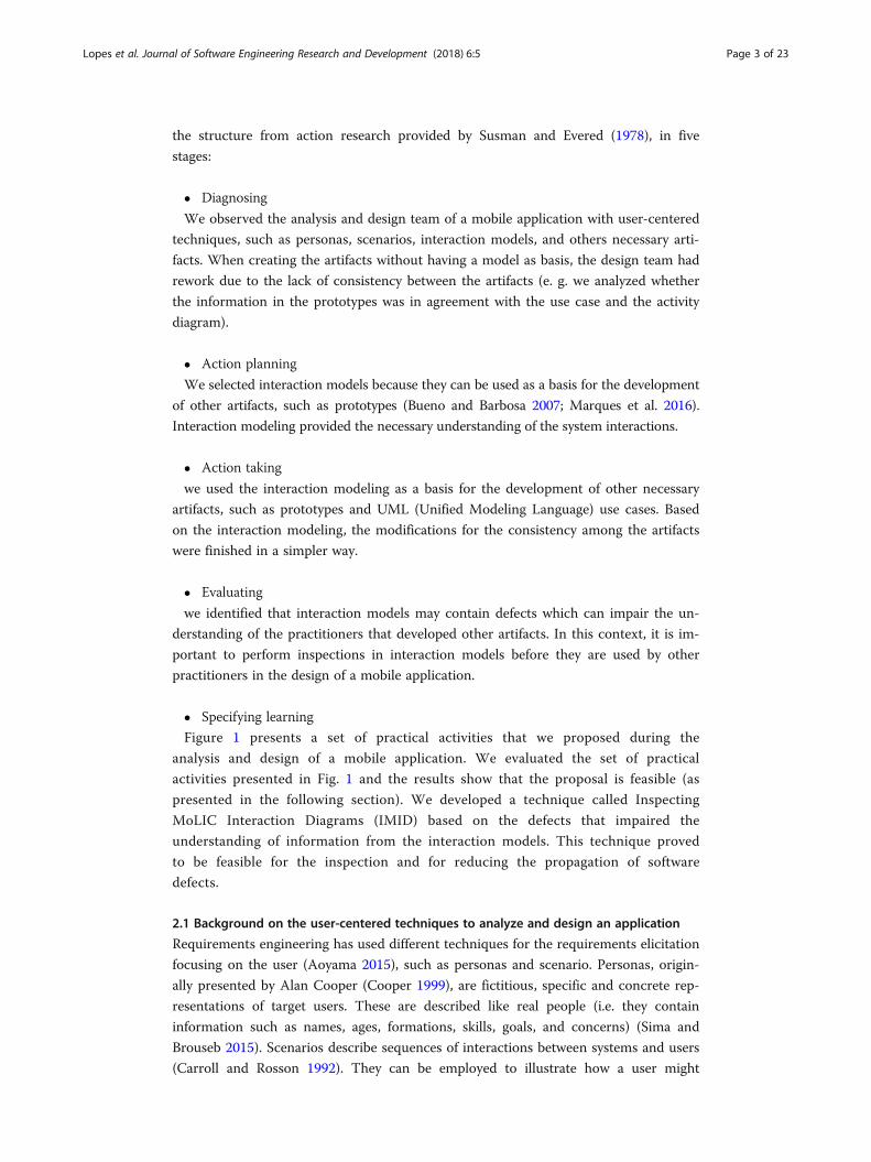
Figure 1 presents a set of practical activities that we proposed during the
analysis and design of a mobile application. We evaluated the set of practical
activities presented in Fig. 1 and the results show that the proposal is feasible (as
presented in the following section). We developed a technique called Inspecting
MoLIC Interaction Diagrams (IMID) based on the defects that impaired the
understanding of information from the interaction models. This technique proved
to be feasible for the inspection and for reducing the propagation of software
defects.
2.1 Background on the user-centered techniques to analyze and design an application
Requirements engineering has used different techniques for the requirements elicitation
focusing on the user (Aoyama 2015), such as personas and scenario. Personas, origin-
ally presented by Alan Cooper (Cooper 1999), are fictitious, specific and concrete rep-
resentations of target users. These are described like real people (i.e. they contain
information such as names, ages, formations, skills, goals, and concerns) (Sima and
Brouseb 2015). Scenarios describe sequences of interactions between systems and users
(Carroll and Rosson 1992). They can be employed to illustrate how a user might
Lopes et al. Journal of Software Engineering Research and Development (2018) 6:5 Page 3 of 23
accomplish particular tasks with the system. According to Benner et al. (1993), scenar-
ios can supplement and support the activities that software engineers perform mentally
on scenarios at the present time, such as uncovering system requirements and evaluat-
ing design alternatives. Scenarios can take many forms and provide various types of in-
formation at different levels of abstraction (Lombriser et al. 2016).
In the design phase, interaction models describe the communication between the
user and the system, specifying when the user can perform specific tasks to achieve
certain goals (Marques et al. 2016). One of the alternatives to support the develop-
ment of interaction models is through MoLIC (Modeling Language for Interaction
as Conversation) (Barbosa and Paula 2003). With the MoLIC models, all inter-
action paths can be represented, including alternative paths for the user to reach
the same goal (Souza and Barbosa 2015). Thus, interaction models can support the
software design with a focus on quality of use, since software engineers can design
all interaction alternatives in the system.
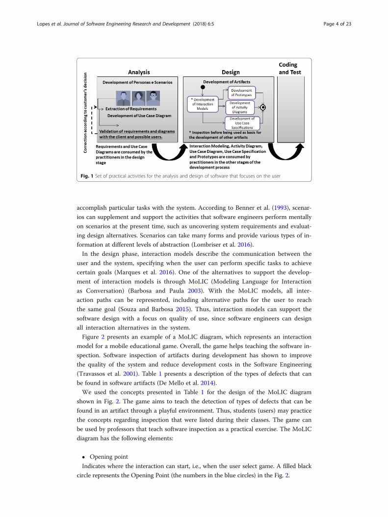
Figure 2 presents an example of a MoLIC diagram, which represents an interaction
model for a mobile educational game. Overall, the game helps teaching the software in-
spection. Software inspection of artifacts during development has shown to improve
the quality of the system and reduce development costs in the Software Engineering
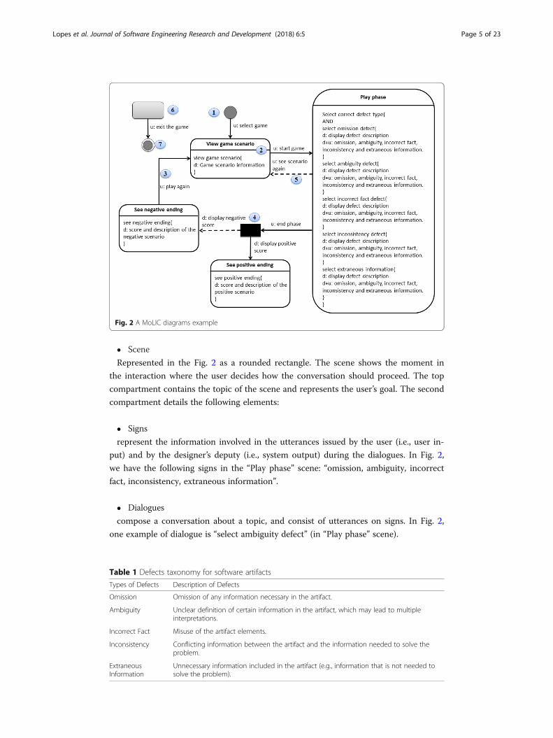
(Travassos et al. 2001). Table 1 presents a description of the types of defects that can
be found in software artifacts (De Mello et al. 2014).
We used the concepts presented in Table 1 for the design of the MoLIC diagram
shown in Fig. 2. The game aims to teach the detection of types of defects that can be
found in an artifact through a playful environment. Thus, students (users) may practice
the concepts regarding inspection that were listed during their classes. The game can
be used by professors that teach software inspection as a practical exercise. The MoLIC
diagram has the following elements:
� Opening point
Indicates where the interaction can start, i.e., when the user select game. A filled black
circle represents the Opening Point (the numbers in the blue circles) in the Fig. 2.
Fig. 1 Set of practical activities for the analysis and design of software that focuses on the user
Lopes et al. Journal of Software Engineering Research and Development (2018) 6:5 Page 4 of 23
� Scene
Represented in the Fig. 2 as a rounded rectangle. The scene shows the moment in
the interaction where the user decides how the conversation should proceed. The top
compartment contains the topic of the scene and represents the user’s goal. The second
compartment details the following elements:
� Signs
represent the information involved in the utterances issued by the user (i.e., user in-
put) and by the designer’s deputy (i.e., system output) during the dialogues. In Fig. 2,
we have the following signs in the “Play phase” scene: “omission, ambiguity, incorrect
fact, inconsistency, extraneous information”.
� Dialogues
compose a conversation about a topic, and consist of utterances on signs. In Fig. 2,
one example of dialogue is “select ambiguity defect” (in “Play phase” scene).
Table 1 Defects taxonomy for software artifacts
Types of Defects Description of Defects
Omission Omission of any information necessary in the artifact.
Ambiguity Unclear definition of certain information in the artifact, which may lead to multipleinterpretations.
Incorrect Fact Misuse of the artifact elements.
Inconsistency Conflicting information between the artifact and the information needed to solve theproblem.
ExtraneousInformation
Unnecessary information included in the artifact (e.g., information that is not needed tosolve the problem).
Fig. 2 A MoLIC diagrams example
Lopes et al. Journal of Software Engineering Research and Development (2018) 6:5 Page 5 of 23
� Structures of dialogues
the dialogues can be composed of other dialogues according to some structure.
In these cases, these structures can be represented by the reserved words SEQ,
XOR, OR or AND. The SEQ structure represents the dialogues that must be ex-
changed in the specified sequence. The XOR structure represents mutually exclu-
sive dialogues. The structure OR represents the choice of exchanging one or more
dialogues. The structure AND represents the use of all dialogs, but not in a prede-
fined sequence. In Fig. 2, the AND structure represents the use of all dialogs, such
as “select omission defect” and “select ambiguity defect”.
� Transition utterance
Represents turn-taking, or rather turn-giving, where either the user or the system
gives the turn to the other, for instance, to change the topic of the conversation. It is
represented by an arrow in the diagram, labeled with a user utterance indicator (u:) or
designer utterance indicator (d:), e.g. “u: play again” in Fig. 2.
� System process
It is represented through a black box in the diagram. It represents the internal pro-
cessing (of a user request) which needs to provide adequate feedback to the user when
there are different outcomes possible, e.g. “See positive ending” and “See negative end-
ing” in Fig. 2.
� Breakdown recovery utterance
is a type of utterance provided to help the user recover from a communication
breakdown. It is represented by a dashed arrow in the diagram, e.g. “see scenario
again” in Fig. 2.
� Ubiquitous access
represents an opportunity for the user to change the topic of the conversation from
any other scene. It is represented through a gray rounded rectangle, e.g. “exit the game”
in Fig. 2.
� Closing point
represents the end of the interaction. A filled black circle within a circle with no pad-
ding represents the Closing Point in the Fig. 2.
Interaction models can be used as a basis for the development of other artifacts,
such as prototypes (Bueno and Barbosa 2007; Marques et al. 2016). In addition,
software engineers can discuss the user-system interaction represented in the
MoLIC diagram in order to collaborate on improving the represented information.
Prototypes in the design phase are interface sketches that reflect customer needs
with regards to more concrete aspects of presentation, from the point of view of
requirements expressed in written language (Luna et al. 2010). The prototypes can
be developed based on the interaction modeling to reflect the decisions of
designers about the paths that the user can follow in the application. Figure 3 pre-
sents prototypes of a mobile application (the educational game) built based on the
MoLIC diagram shown in Fig. 2. We will now describe the decisions for the
Lopes et al. Journal of Software Engineering Research and Development (2018) 6:5 Page 6 of 23
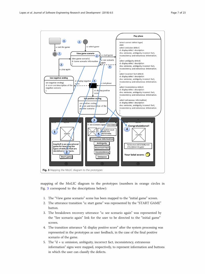
mapping of the MoLIC diagram to the prototypes (numbers in orange circles in
Fig. 3 correspond to the descriptions below):
1. The “View game scenario” scene has been mapped to the “initial game” screen.
2. The utterance transition “u: start game” was represented by the “START GAME”
button.
3. The breakdown recovery utterance “u: see scenario again” was represented by
the “See scenario again” link for the user to be directed to the “initial game”
screen.
4. The transition utterance “d: display positive score” after the system processing was
represented in the prototypes as user feedback, in the case of the final positive
scenario of the game.
5. The “d + u: omission, ambiguity, incorrect fact, inconsistency, extraneous
information” signs were mapped, respectively, to represent information and buttons
in which the user can classify the defects.
Fig. 3 Mapping the MoLIC diagram to the prototypes
Lopes et al. Journal of Software Engineering Research and Development (2018) 6:5 Page 7 of 23
2.2 Developed application and practices adopted for the development of artifacts in the
analysis and design phases
The research presented in this phase refers to the work of the analysis and design team
of an application called HCDP (Home Care Development Project). The motivation for
the development of this application is the difficulty of family members trying to manage
the routine activities of an elderly person. The HCDP application was developed to
support a group of people, being family members and caregivers of the elderly, who
took care of an elderly in a collaborative way. This application was part of a cooper-
ation project among the Federal University of Amazonas, Pontifical Catholic University
of Rio Grande do Sul and Samsung Research Brazil. Three distributed teams worked in
the development of the HCDP application. The management team (Customer) defined
all the functionalities to be developed and the artifacts that should be delivered. An-
other team performed the activities related to the application coding. The remaining
team performed the activities related to the analysis and design of the application. The
analysis and design team was composed of five software engineers and a project
manager.
The authors of this paper were part of the analysis and design team of the HCDP ap-
plication. In order to develop the HCDP application, we adopted the Scrum method-
ology (Scrum Alliance 2016). Scrum focus on collaborative teamwork and explicitly
acknowledge the importance of self-organization and is the most often employed agile
methodology (Hron and Obwegeser 2018). We adopted some practices from the Scrum
methodology, such as: (i) the products are delivered in increments called “Sprints”. The
duration of each sprint was four weeks. Each sprint starts with a (ii) sprint planning
meeting and a (iii) retrospective meeting may be scheduled to assess the team. We
chose Scrum methodology because the management team requested the iterative and
incremental development of the artifacts; and the team adopted transparency in the
progress of activities.
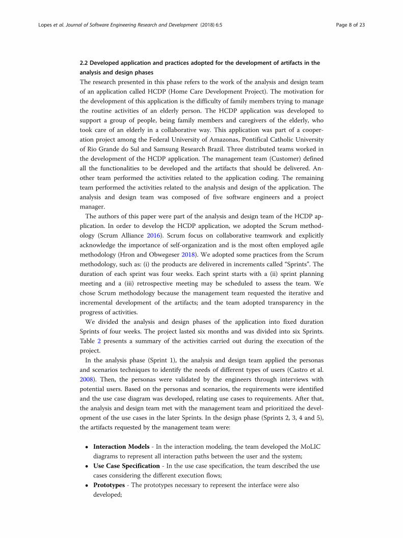
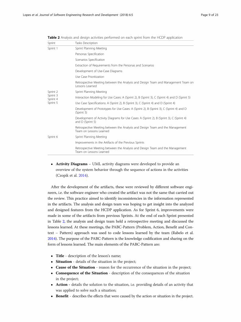
We divided the analysis and design phases of the application into fixed duration
Sprints of four weeks. The project lasted six months and was divided into six Sprints.
Table 2 presents a summary of the activities carried out during the execution of the
project.
In the analysis phase (Sprint 1), the analysis and design team applied the personas
and scenarios techniques to identify the needs of different types of users (Castro et al.
2008). Then, the personas were validated by the engineers through interviews with
potential users. Based on the personas and scenarios, the requirements were identified
and the use case diagram was developed, relating use cases to requirements. After that,
the analysis and design team met with the management team and prioritized the devel-
opment of the use cases in the later Sprints. In the design phase (Sprints 2, 3, 4 and 5),
the artifacts requested by the management team were:
� Interaction Models - In the interaction modeling, the team developed the MoLIC
diagrams to represent all interaction paths between the user and the system;
� Use Case Specification - In the use case specification, the team described the use
cases considering the different execution flows;
� Prototypes - The prototypes necessary to represent the interface were also
developed;
Lopes et al. Journal of Software Engineering Research and Development (2018) 6:5 Page 8 of 23
� Activity Diagrams – UML activity diagrams were developed to provide an
overview of the system behavior through the sequence of actions in the activities
(Czopik et al. 2014).
After the development of the artifacts, these were reviewed by different software engi-
neers, i.e. the software engineer who created the artifact was not the same that carried out
the review. This practice aimed to identify inconsistencies in the information represented
in the artifacts. The analysis and design team was hoping to get insight into the analyzed
and designed features from the HCDP application. As for Sprint 6, improvements were
made in some of the artifacts from previous Sprints. At the end of each Sprint presented
in Table 2, the analysis and design team held a retrospective meeting and discussed the
lessons learned. At these meetings, the PABC-Pattern (Problem, Action, Benefit and Con-
text – Pattern) approach was used to code lessons learned by the team (Rabelo et al.
2014). The purpose of the PABC-Pattern is the knowledge codification and sharing on the
form of lessons learned. The main elements of the PABC-Pattern are:
� Title - description of the lesson’s name;
� Situation - details of the situation in the project;
� Cause of the Situation - reason for the occurrence of the situation in the project;
� Consequence of the Situation - description of the consequences of the situation
in the project;
� Action - details the solution to the situation, i.e. providing details of an activity that
was applied to solve such a situation;
� Benefit - describes the effects that were caused by the action or situation in the project.
Table 2 Analysis and design activities performed on each sprint from the HCDP application
Sprint Tasks Description
Sprint 1 Sprint Planning Meeting
Personas Specification
Scenarios Specification
Extraction of Requirements from the Personas and Scenarios
Development of Use-Case Diagrams
Use Case Prioritization
Retrospective Meeting between the Analysis and Design Team and Management Team onLessons Learned
Sprint 2Sprint 3Sprint 4Sprint 5
Sprint Planning Meeting
Interaction Modeling for Use Cases: A (Sprint 2), B (Sprint 3), C (Sprint 4) and D (Sprint 5)
Use Case Specifications: A (Sprint 2), B (Sprint 3), C (Sprint 4) and D (Sprint 4)
Development of Prototypes for Use Cases: A (Sprint 2), B (Sprint 3), C (Sprint 4) and D(Sprint 5)
Development of Activity Diagrams for Use Cases: A (Sprint 2), B (Sprint 3), C (Sprint 4)and D (Sprint 5)
Retrospective Meeting between the Analysis and Design Team and the ManagementTeam on Lessons Learned
Sprint 6 Sprint Planning Meeting
Improvements in the Artifacts of the Previous Sprints
Retrospective Meeting between the Analysis and Design Team and the ManagementTeam on Lessons Learned
Lopes et al. Journal of Software Engineering Research and Development (2018) 6:5 Page 9 of 23
2.2.1 Activities of the analysis phase of the development process of the HCDP application
In Sprint 1, personas and scenarios were created with the purpose of understand-
ing the different types of user of the application to be designed. The HCDP ap-
plication should control the activities of an elderly person (e.g. go to the doctor,
take medication, meals, and others). Therefore, the created personas represented
family members and caregivers of the elderly. For the creation of personas, we
used a template containing the following information: identification data, housing
conditions, degree of experience with technologies, degree of responsibility, learn-
ing style, acceptance of change and the context of use of the application. After
that, scenarios were developed with the details of the relationship between the
personas and the mobile devices.
The scenarios show the relationship between the personas, which are related to
the activity of notifying family members and caregivers about the elderly’s
appointments. To prepare the scenarios, we used a template composed of the
following information: Context, goals, events and actions. From this scenario, the
following requirements for the development of the application were identified: “To notify
that the activities of the elderly routine have been fulfilled” - Requirement 1; “To notify
that the activities of the elderly routine have not been fulfilled” - Requirement 2.
Based on these requirements, we developed the HCDP use case diagram. After
performing these activities, the management team of the HCDP project and the
analysis and design team prioritized together the development of use cases that
would be developed in the other Sprints.
2.2.2 Activities of the design phase of the development process of the HCDP
Sprint 2 began the activities of the design phase. First, the analysis and design team
selected one of the use cases according to the priority order defined in Sprint 1. After
that, all the artifacts requested by the management team were developed. Different
engineers were responsible for the development of interaction models, prototypes, use
case specification and activity diagrams. The activities are described below.
A. Analysis of the development of artifacts in Sprint 2
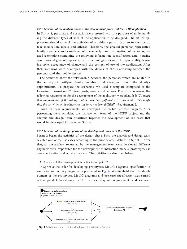
In Sprint 2, the order for developing prototypes, MoLIC diagrams, specification of
use cases and activity diagrams is presented in Fig. 4. We highlight that the devel-
opment of the prototypes, MoLIC diagrams and use case specification was carried
out in parallel, based only on the use case diagram, requirements and scenario.
Fig. 4 Activities performed for the development of artifacts in Sprint 2
Lopes et al. Journal of Software Engineering Research and Development (2018) 6:5 Page 10 of 23
The use case diagram, requirements and scenario were discussed prior to the de-
velopment of the prototypes, MoLIC diagrams and the use case specification. The
project manager requested the development of these artifacts separately in order to
assign different responsibilities to the software engineers and facilitate the process
of developing the artifacts. Then, the engineers analyzed the consistency between
created artifacts regarding the information with respect to the functionalities
(dashed arrow in Fig. 4). The activity diagram was created, based on the three
previously developed artifacts (prototypes, MoLIC diagrams and use case specifi-
cation). At the end of Sprint 2, after the development of all artifacts, a retro-
spective meeting of the analysis and design team was held. The following are
some of the lessons learned from Sprint 2.
In Sprint 2, there were 15 documents that reported the lessons learned that were
coded using the PABC-Pattern approach, with a total of 7 documents related to the de-
velopment of artifacts. The main three lessons learned that report problems in the de-
velopment of the artifacts were selected. One of these lessons learned has the Title:
Rework by maintaining the artifact pattern, which was generated by the following
Situation: “When developing the separate artifacts after the meeting, there is a lot of
work in standardizing the use cases, prototypes, interaction modeling and activity
diagram”. The analysis and design team defined the following Action strategy: “A joint
analysis where the main idea of the requirements will be defined before creating the
artifacts through a formal document”. Thus, the team concluded that rework can be
reduced with regards to inconsistencies between such artifacts.
The lesson learned that has the Title: Dependence between activities can cause
delays in the project, occurred due to the following Situation: “The improvement of the
use case depended on the delivery of the prototypes. The delivery of the prototypes was
delayed”. As a result, the following Consequence of the Situation was observed:
“Rework. Delay of the next activity that should be delivered to another participant”. There-
fore, we can notice that there was a delay in the specification of use cases, since such an
artifact should represent the same information in the prototypes and MoLIC diagrams.
The lesson learned that has the Title: Lack of traceability between the prototypes
and the use case, occurred due to the following Situation: “Lack of traceability or
mapping to understand what is in the prototypes and what it represents in the use case”.
The analysis and design team defined the following Action strategy: “To verify which
prototypes are represented in the use case and integrate the two artifacts”. Therefore,
there was a lack of understanding of some software engineers regarding the under-
standing of the requirements for the development of different artifacts. As a result,
there were inconsistencies about the information of the HCDP application among the
developed artifacts based on the requirements, use case diagram and scenario.
We highlight that in Sprint 2 the MoLIC diagrams were not used as basis for the de-
velopment of the other artifacts. Therefore, there was no artifact that represented the
essential information in the user-system interaction for the development of the other
artifacts. For this reason, there was rework of the analysis and design team with regards
to the consistency of the artifacts. This rework was due to the team’s lack of knowledge
regarding the most appropriate order for the development of artifacts. To mitigate this
problem, the team made a change in the order of development of the artifacts. This
change is shown in the next subsection.
Lopes et al. Journal of Software Engineering Research and Development (2018) 6:5 Page 11 of 23
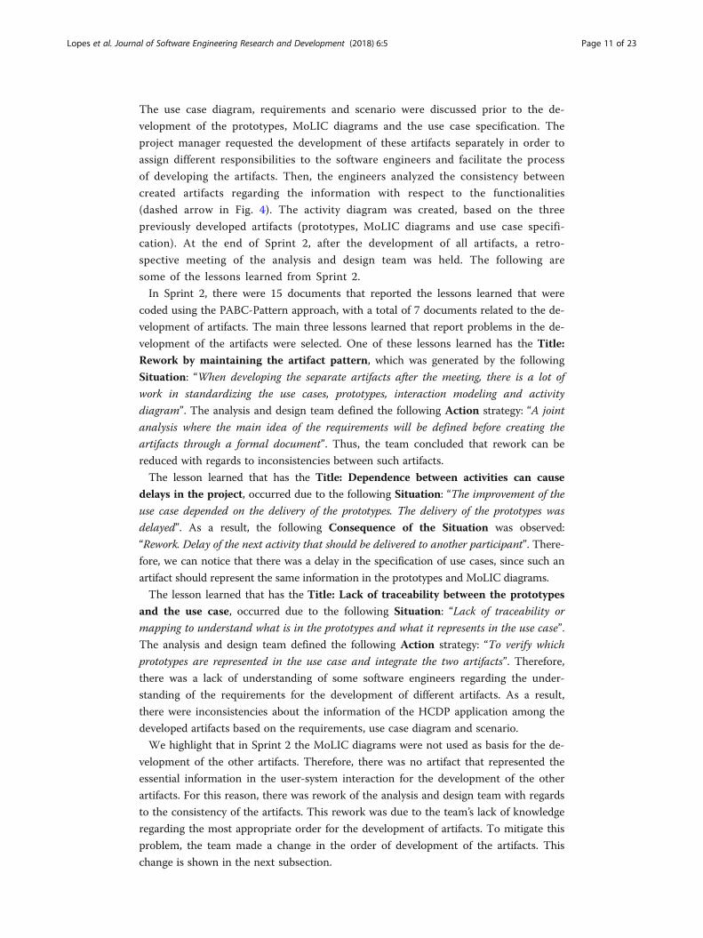
B. Analysis of the development of artifacts in Sprint 3
In Sprint 3, the order of developing the MoLIC diagrams, prototypes, use case spe-
cification, and activity diagrams is presented in Fig. 5. This order of development
is different with regards to the design activities in Sprint 2. The development of
prototypes, activity diagrams and use case specifications was based on the MoLIC
diagrams, requirements, use case diagrams and scenario. The project manager
adopted this approach based on the lessons learned from Sprint 2 and the litera-
ture suggestions (Bueno and Barbosa 2007; Marques et al. 2016) on using the
interaction modeling as a basis for the development of other artifacts. In similar
way to Sprint 2, the engineers analyzed the consistency between these artifacts
developed about their information (dashed arrow in Fig. 5).
In Sprint 3, the analysis and design team carried out a joint elaboration of the interaction
modeling, that is, the software engineer responsible for the interaction modeling developed
the MoLIC diagrams, while the other engineers discussed the interaction solutions. After
doing this, the prototypes, activity diagram and case specification were developed, using
the MoLIC diagrams as basis. At the end of Sprint 3, a retrospective meeting of the HCDP
project was also held. Here, we present some of the lessons identified in Sprint 3.
Regarding the lessons learned from the Sprint team, there were 12 documents that
report a coding of lessons learned, with a total of 4 documents related to the develop-
ment of the artifacts. We selected the main three lessons learned on the use of MoLIC
diagrams as the basis for the development of the other artifacts.
A lesson learned about the use of MoLIC in Sprint 3 has the Title: Using
MoLIC diagrams at the beginning, which was caused by the following Situation:
“The use of the MoLIC diagrams at the beginning made it possible to think about
the use case. Also, it enabled seeing that it is necessary to use the diagrams along
with the interface”. This coded lesson learned was assigned to the following Conse-
quence of the Situation: “Based on the MoLIC diagrams, the team ended up gain-
ing time and, at the end of the sprint, the modifications were finished in a simpler
way”. However, the modifications in the prototypes made the analysis and design
team think on modifications that must be made in the MoLIC diagram, since such
models can be designed together (Lopes et al. 2015). Regarding the Action strat-
egies, for this codification, there was no action planned to be defined, because the
experience was considered positive.
Fig. 5 Activities performed for the development of the artifacts in Sprint 3
Lopes et al. Journal of Software Engineering Research and Development (2018) 6:5 Page 12 of 23
Another selected lesson that has the Title: Thinking about time consumption
in the project activities, which occurred as shown by the following Situation:
“Benefits in activities that consumed design time and were not well understood by
the participants”. The analysis and design team defined the following Action strat-
egy: “Participants have to think that when there is no interface pattern, starting
with the interaction modeling makes sense”. Therefore, the analysis and design team
concluded that the use of initial interaction modeling is useful to understand the
system’s functionalities. Furthermore, in this project there was a better understand-
ing of the functionalities from the MoLIC diagrams together with the prototypes.
Based on these lessons learned, we can identify the following positive aspects: (a) the
use of MoLIC diagrams in the beginning to understand the functionalities and (b) their
use as a basis for the development of other artifacts.
C. Analysis of the use of interaction models as basis for the development of other
artifacts in Sprint 3
Besides the documents with the coded lessons learned, the document containing the
review of the interaction model was analyzed in Sprint 3. Only the document with the
interaction model review from the Sprint was chosen for this analysis because it was
used by the software engineers as the basis for creating other artifacts. This document
included the MoLIC diagrams and other information necessary to understand what
problems may have occurred after defining the interaction model at the beginning of
the sprint.
We carried out the review of the MoLIC diagrams based on the taxonomy presented
by De Mello et al. (2014) in Table 1. The MoLIC diagrams review document identifies,
for example, an inconsistency defect of the message displayed to the user. The defect
could impact in development of the prototypes and the specification of use cases, since
the information would be mapped inconsistently with the system requirements. In
addition, we identified an omission defect of information about the description for de-
tails of the user. These defects could impact in development of the prototypes, since
the information would not be mapped. The defects presented were found in the case
study presented in the work by Lopes et al. (2015), based on the taxonomy presented
by De Mello et al. (2014). Consequently, it is important to review the interaction
models, because the defects may undermine the practitioners’ understanding of the ar-
tifacts that were developed based on the MoLIC diagrams. This practice was performed
in the interaction modeling document and in the other artifacts before being delivered
to the analysis and design.
Although the review activity was performed on the MoLIC diagrams by another soft-
ware engineer, we highlight that such review was not performed with a specific tech-
nique for reviewing MoLIC diagrams. Possibly, the use of a specific technique could
have aided in identifying more defects prior to the development of the prototypes and
use case specification. Thus, it was necessary to correct the MoLIC diagrams, specifica-
tion of use cases and prototypes due to such defects.
2.3 A technique for inspecting MoLIC interaction diagrams
An inspection helps identifying defects during the development process (Taba and
Siew 2012). The main purpose of an inspection is to identify defects in software
Lopes et al. Journal of Software Engineering Research and Development (2018) 6:5 Page 13 of 23
development to reduce costs and improve software quality (Qazi et al. 2016). The
importance of conducting inspections during the development process is broadly
cited in the literature (Aurum et al. 2002; Misra et al. 2014). Regarding the MoLIC
diagrams, these diagrams should be also verified regarding their consistency and
completeness to reduce the number of defects and to prevent them from propagating
defects to derived artifacts. As suggested by Lopes et al. (2015), MoLIC diagrams may
contain defects, which can impair the understanding of the practitioners.
We developed a technique for Inspecting MoLIC Interaction Diagrams (IMID) based
on the different types of defects found in the MoLIC diagram for the HCDP application
from Sprint 3, such as Omission, Ambiguity, and others (De Mello et al. 2014). Table 3
presents the IMID technique. The verification items assess both the consistency of the
MoLIC diagrams with the requirements and their completeness. The IMID technique was
developed because we did not find a technique in the literature for the inspection of
MoLIC diagrams with regards to the requirements. We believe that these verification
items can be instantiated for other interaction modeling notations, as long as the elements
have the same purpose in the interaction modeling. We applied this technique in Sprints
4 and 5, as follows: After the software engineer responsible for the interaction modeling
finished the diagram, the reviewer responsible for the verification of the interaction model
used the IMID technique with the aid of a defects reporting form.
We analyzed the use of the IMID technique for the inspection of MoLIC dia-
grams in the Sprint 4 and 5. In the Sprint 4, the MoLIC diagrams contained a
total of 5 defects; and, in the Sprint 5, the MoLIC diagrams contained a total of 6
defects. Figure 6 presents examples of some of the identified defects found with
the technique by the reviewer of interaction modeling. In this sense, we present:
the identifier of the defect (e.g. “Verification item 1”), the verification item descrip-
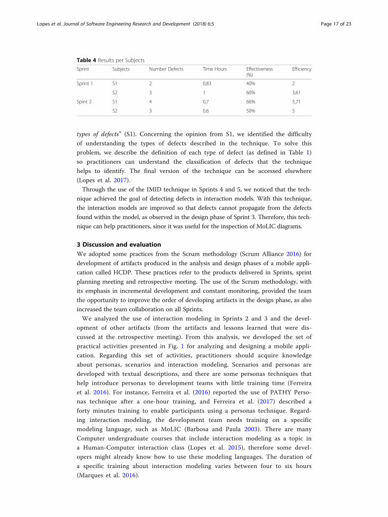
tion of the IMID and the type of identified defect. The number of defects, the in-
spection time and the indicators of effectiveness and efficiency of each subject
(software engineer responsible for the verification of the interaction model used
the IMID technique) are described in Table 4 (for Sprint 4 and 5). The indicators
of effectiveness and efficiency that were adopted, this is often used in studies
investigating inspection techniques, such as inspection techniques for models
(Fernandez et al. 2012). The effectiveness was calculated using the number of de-
fects found by the subjects divided by the total number of defects from the oracle.
The efficiency was calculated on the number of defects found divided by the time
of inspection of each subject. We refer to the subjects using the letter S#, where
# is a number that uniquely identifies each software engineer.
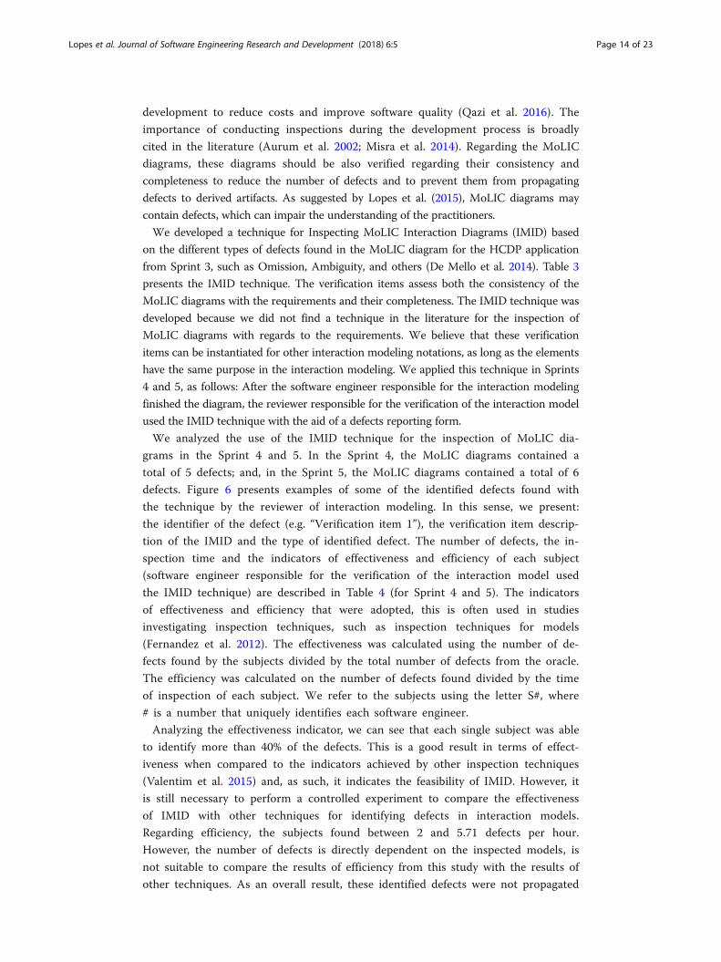
Analyzing the effectiveness indicator, we can see that each single subject was able
to identify more than 40% of the defects. This is a good result in terms of effect-
iveness when compared to the indicators achieved by other inspection techniques
(Valentim et al. 2015) and, as such, it indicates the feasibility of IMID. However, it
is still necessary to perform a controlled experiment to compare the effectiveness
of IMID with other techniques for identifying defects in interaction models.
Regarding efficiency, the subjects found between 2 and 5.71 defects per hour.
However, the number of defects is directly dependent on the inspected models, is
not suitable to compare the results of efficiency from this study with the results of
other techniques. As an overall result, these identified defects were not propagated
Lopes et al. Journal of Software Engineering Research and Development (2018) 6:5 Page 14 of 23
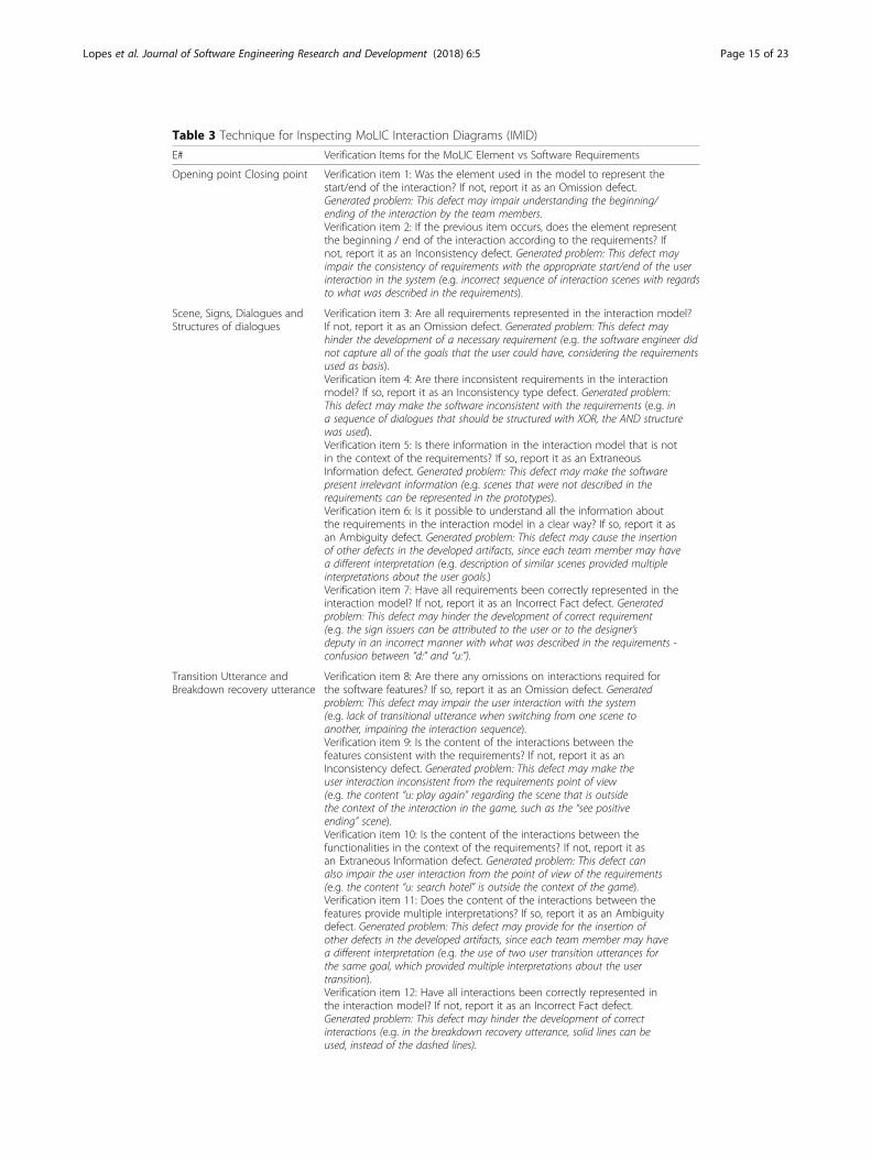
Table 3 Technique for Inspecting MoLIC Interaction Diagrams (IMID)
E# Verification Items for the MoLIC Element vs Software Requirements
Opening point Closing point Verification item 1: Was the element used in the model to represent thestart/end of the interaction? If not, report it as an Omission defect.Generated problem: This defect may impair understanding the beginning/ending of the interaction by the team members.Verification item 2: If the previous item occurs, does the element representthe beginning / end of the interaction according to the requirements? Ifnot, report it as an Inconsistency defect. Generated problem: This defect mayimpair the consistency of requirements with the appropriate start/end of the userinteraction in the system (e.g. incorrect sequence of interaction scenes with regardsto what was described in the requirements).
Scene, Signs, Dialogues andStructures of dialogues
Verification item 3: Are all requirements represented in the interaction model?If not, report it as an Omission defect. Generated problem: This defect mayhinder the development of a necessary requirement (e.g. the software engineer didnot capture all of the goals that the user could have, considering the requirementsused as basis).Verification item 4: Are there inconsistent requirements in the interactionmodel? If so, report it as an Inconsistency type defect. Generated problem:This defect may make the software inconsistent with the requirements (e.g. ina sequence of dialogues that should be structured with XOR, the AND structurewas used).Verification item 5: Is there information in the interaction model that is notin the context of the requirements? If so, report it as an ExtraneousInformation defect. Generated problem: This defect may make the softwarepresent irrelevant information (e.g. scenes that were not described in therequirements can be represented in the prototypes).Verification item 6: Is it possible to understand all the information aboutthe requirements in the interaction model in a clear way? If so, report it asan Ambiguity defect. Generated problem: This defect may cause the insertionof other defects in the developed artifacts, since each team member may havea different interpretation (e.g. description of similar scenes provided multipleinterpretations about the user goals.)Verification item 7: Have all requirements been correctly represented in theinteraction model? If not, report it as an Incorrect Fact defect. Generatedproblem: This defect may hinder the development of correct requirement(e.g. the sign issuers can be attributed to the user or to the designer’sdeputy in an incorrect manner with what was described in the requirements -confusion between “d:” and “u:”).
Transition Utterance andBreakdown recovery utterance
Verification item 8: Are there any omissions on interactions required forthe software features? If so, report it as an Omission defect. Generatedproblem: This defect may impair the user interaction with the system(e.g. lack of transitional utterance when switching from one scene toanother, impairing the interaction sequence).Verification item 9: Is the content of the interactions between thefeatures consistent with the requirements? If not, report it as anInconsistency defect. Generated problem: This defect may make theuser interaction inconsistent from the requirements point of view(e.g. the content “u: play again” regarding the scene that is outsidethe context of the interaction in the game, such as the “see positiveending” scene).Verification item 10: Is the content of the interactions between thefunctionalities in the context of the requirements? If not, report it asan Extraneous Information defect. Generated problem: This defect canalso impair the user interaction from the point of view of the requirements(e.g. the content “u: search hotel” is outside the context of the game).Verification item 11: Does the content of the interactions between thefeatures provide multiple interpretations? If so, report it as an Ambiguitydefect. Generated problem: This defect may provide for the insertion ofother defects in the developed artifacts, since each team member may havea different interpretation (e.g. the use of two user transition utterances forthe same goal, which provided multiple interpretations about the usertransition).Verification item 12: Have all interactions been correctly represented inthe interaction model? If not, report it as an Incorrect Fact defect.Generated problem: This defect may hinder the development of correctinteractions (e.g. in the breakdown recovery utterance, solid lines can beused, instead of the dashed lines).
Lopes et al. Journal of Software Engineering Research and Development (2018) 6:5 Page 15 of 23
to artifacts that were developed based on the MoLIC diagram, thereby reducing
analysis and design rework.
After Sprints 4 and 5, we conducted an interviewed with two software engineers
(subjects) who used IMID during the design phase. We asked the following ques-
tion was for software engineers: Please report your perceptions about the IMID
technique? Regarding the positive aspects of the technique, the software engineers
quoted the following: “I believe that the items guided me well to find defects in the
diagram” (S1) and “I consider that this technique helps finding defects in the dia-
gram before creating other artifacts” (S2). However, S1 also reported a negative as-
pect of the technique: “I had trouble in remembering the difference between the
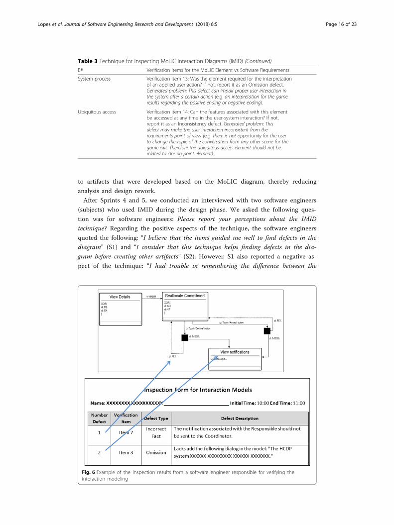
Table 3 Technique for Inspecting MoLIC Interaction Diagrams (IMID) (Continued)
E# Verification Items for the MoLIC Element vs Software Requirements
System process Verification item 13: Was the element required for the interpretationof an applied user action? If not, report it as an Omission defect.Generated problem: This defect can impair proper user interaction inthe system after a certain action (e.g. an interpretation for the gameresults regarding the positive ending or negative ending).
Ubiquitous access Verification item 14: Can the features associated with this elementbe accessed at any time in the user-system interaction? If not,report it as an Inconsistency defect. Generated problem: Thisdefect may make the user interaction inconsistent from therequirements point of view (e.g. there is not opportunity for the userto change the topic of the conversation from any other scene for thegame exit. Therefore the ubiquitous access element should not berelated to closing point element).
Fig. 6 Example of the inspection results from a software engineer responsible for verifying theinteraction modeling
Lopes et al. Journal of Software Engineering Research and Development (2018) 6:5 Page 16 of 23
types of defects” (S1). Concerning the opinion from S1, we identified the difficulty
of understanding the types of defects described in the technique. To solve this
problem, we describe the definition of each type of defect (as defined in Table 1)
so practitioners can understand the classification of defects that the technique
helps to identify. The final version of the technique can be accessed elsewhere
(Lopes et al. 2017).
Through the use of the IMID technique in Sprints 4 and 5, we noticed that the tech-
nique achieved the goal of detecting defects in interaction models. With this technique,
the interaction models are improved so that defects cannot propagate from the defects
found within the model, as observed in the design phase of Sprint 3. Therefore, this tech-
nique can help practitioners, since it was useful for the inspection of MoLIC diagrams.
3 Discussion and evaluationWe adopted some practices from the Scrum methodology (Scrum Alliance 2016) for
development of artifacts produced in the analysis and design phases of a mobile appli-
cation called HCDP. These practices refer to the products delivered in Sprints, sprint
planning meeting and retrospective meeting. The use of the Scrum methodology, with
its emphasis in incremental development and constant monitoring, provided the team
the opportunity to improve the order of developing artifacts in the design phase, as also
increased the team collaboration on all Sprints.
We analyzed the use of interaction modeling in Sprints 2 and 3 and the devel-
opment of other artifacts (from the artifacts and lessons learned that were dis-
cussed at the retrospective meeting). From this analysis, we developed the set of
practical activities presented in Fig. 1 for analyzing and designing a mobile appli-
cation. Regarding this set of activities, practitioners should acquire knowledge
about personas, scenarios and interaction modeling. Scenarios and personas are
developed with textual descriptions, and there are some personas techniques that
help introduce personas to development teams with little training time (Ferreira
et al. 2016). For instance, Ferreira et al. (2016) reported the use of PATHY Perso-
nas technique after a one-hour training, and Ferreira et al. (2017) described a
forty minutes training to enable participants using a personas technique. Regard-
ing interaction modeling, the development team needs training on a specific
modeling language, such as MoLIC (Barbosa and Paula 2003). There are many
Computer undergraduate courses that include interaction modeling as a topic in
a Human-Computer interaction class (Lopes et al. 2015), therefore some devel-
opers might already know how to use these modeling languages. The duration of
a specific training about interaction modeling varies between four to six hours
(Marques et al. 2016).
Table 4 Results per Subjects
Sprint Subjects Number Defects Time Hours Effectiveness(%)
Efficiency
Sprint 1 S1 2 0,83 40% 2
S2 3 1 60% 3,61
Spint 2 S1 4 0,7 66% 5,71
S2 3 0,6 50% 5
Lopes et al. Journal of Software Engineering Research and Development (2018) 6:5 Page 17 of 23
Although there is a learning curve, such activities provide a better support for the de-
velopment of user-centered applications. In addition, the adoption of these activities
provides better team communication regarding users and their needs during the whole
design process; and helps teams on decision-making about efficient design (Mashapa et
al. 2013; Marques et al. 2017).
The set of practical activities was used in Sprints 3, 4 and 5; and caused the re-
duction of rework in Sprints 3, 4 and 5 when compared with the rework from
Sprint 2. We applied a Focus Groups (FG) (De França et al. 2015) to evaluate
the perceptions from the analysis and design team perceptions about the set of
practical activities presented in Fig. 1. FG is a qualitative technique for collecting
data by organizing group interviews to discuss a certain object of study. It determines
how a researcher has to choose moderators, questions and participants. All software engi-
neers participated in the FG, including the software engineers who used IMID to inspect
the MoLIC diagrams (S1 and S2). The software engineer responsible for the interaction
modeling and manager of the design team were the moderator in the FG. We also refer to
the software engineers using the S# for identifies each software engineer. The following
question was asked to the software engineers to them answer: Please report your percep-
tions about the set of practical activities used in the HCDP. In the FG discussion, the team
reported in the FG board that:
“I found it great to have the interaction model for developing prototypes. I mapped
the information in the prototypes from the diagram, which improved my performance
in this activity” (S3).
“I believe that the definition of these activities helped each team member carry out
his/her tasks and improved our communication. The team was already aware of
what they would do; and we found fewer errors in evaluating the consistency of the
developed artifacts” (S4).
“The dependency between activities can cause rework, as in Sprint 2. With the set of
activities, we did not have this problem. In addition, we do not become idle” (S2).
“The interaction modeling meetings provided a better understanding of the artifacts
to the team members” (S1).
members in the FG, it was possible to obtain indications about the benefits of using the
set of practical activities proposed in this research. However, if the MoLIC diagrams
have defects, this will prejudice the understanding of the involved practitioners. These
defects can cause rework in both the MoLIC diagrams and the artifacts developed
based on the diagrams. For this reason, we suggest that the developed interaction
models are inspected before being used as basis for the development of other artifacts.
Through this research, we observed the experience of this analysis and design
team when applying user-centered techniques, we suggested personas and scenarios
for the understanding of requirements; and we carried out interaction modeling at
the beginning of the design phase in order to develop other software artifacts, such
as the specification of use cases, prototypes, and activity diagrams. Through the
Lopes et al. Journal of Software Engineering Research and Development (2018) 6:5 Page 18 of 23
use of interaction models it is possible to design and detect possible problems in
the user-system interaction during the design phase of the system. Thus, it is pos-
sible to develop user-centered software.
In addition, we highlight the importance of carrying out meetings on the lessons
learned for the team’s understanding of the project’s analysis and design activities.
Regarding the lessons learned from Sprint 2, there was a rework of the design
team with regards to the consistency of the artifacts developed. This was due to
the lack of an artifact that represented the essential information in the user-system
interaction for the development of the other artifacts. Based on the lessons learned
from Sprint 2 and the literature suggestions (Bueno and Barbosa 2007; Marques et
al. 2016), the design team adopted the interaction modeling as a basis for the de-
velopment of other artifacts. The use of interaction modeling provided the neces-
sary understanding of the system interactions and the modifications for the
consistency among the artifacts were finished in a simpler way. These lessons
learned can help software engineers understanding our proposal of a set of prac-
tical activities. Thus, it is possible to improve the execution of activities when ana-
lyzing and designing applications.
3.1 Related work
Regarding the practice with the user-centered techniques used in the HCDP, we did
not find any other works on how software engineers used these techniques together in
the initial stages of the development process. In general, studies assess the techniques
individually for specific contexts.
Choma et al. (2016) used Personas to facilitate the communication between the
UX and Scrum teams due to differences in vocabulary. Furthermore, personas are
recognized by UX practitioners as a good practice to keep the software develop-
ment focus on the users’ needs. In their development process, they created user
stories based on the created personas. In our work, we created scenarios and use
cases based on the created personas.
Regarding the interaction modeling with MoLIC, Silva et al. (2006) proposed the
Extreme Designing methodology for interaction design through the use of prototypes
and MoLIC diagrams. The methodology aims to unify the vision represented by the
prototypes. In our work, in addition to analyzing the use of interaction models and
prototypes, we verified that it is possible to use it for UML diagrams. Sangiorgi and
Barbosa (2009) developed the MoLIC Designer tool to support the creation of MoLIC
diagrams, avoiding the insertion of syntax defects. We used the MoLIC Designer tool
in our research. However, we identified the need to inspect defects that affect the rela-
tionship between the MoLIC diagrams and the application domain. As a result, we have
developed the IMID technique, which allows the inspection of different types of defects
between the MoLIC diagrams and the application requirements.
3.2 Threats to validity and limitations
During the analysis, we tried to mitigate the “researcher bias” about the interpretation
of the software engineers’ perceptions. Therefore, to address the threats to valid inter-
pretation of the results, the questions regarding the set of practical activities and IMID
were formulated to encourage the interviewees to express his/her own opinion. In
Lopes et al. Journal of Software Engineering Research and Development (2018) 6:5 Page 19 of 23
addition, we discuss the validity threats according to the classification provided by
Wohlin et al. (2000). We analyzed the following threats that may affect the validity of
the results from this experience report, which are:
� Internal validity
The expectation of the software engineer responsible for the MoLIC diagrams regard-
ing the benefits of carrying out interaction modeling: This may have influenced the de-
signer responsible for building the MoLIC diagrams to obtain positive results in the
design phase. However, we emphasize that none of the team’s designers had any rela-
tionship with the authorship of the MoLIC diagrams. In addition, the lessons learned
were codified by a team member who had not participated in the development of the
MoLIC diagrams. Therefore, the results of the lessons learned address only the team’s
conclusion for each Sprint.
� External validity
MoLIC diagrams as a basis artifact for the development of other artifacts for a mobile
application: It is not possible to state that the same benefits can be generalized to dif-
ferent types of applications, such as web or desktop. It is important to understand the
use of diagrams for different types of applications. However, the focus on this research
is to increase the understanding of the user-centered techniques in the software
development.
� Conclusion validity
Small sample: Regarding the analysis and design team, these results were obtained
from a single team. Therefore, the results are not generalizable, but are considered valid
for the project context.
4 ConclusionsThis paper described a research about the analysis and design team with user-centered
techniques, such as personas, scenarios and interaction modeling. In this research, indus-
try and academy worked together for the development of a mobile application. On the
analysis phase, the personas and scenarios provided the understanding of the users of the
HCDP application and the extraction of its requirements. In the design phase, the inter-
action modeling provided the team with the necessary understanding of the system inter-
action alternatives for the users. Therefore, we used the interaction modeling as a basis
for the development of other required artifacts of the application. Based on our research,
we suggest this set of practical activities for the analysis and design of user-centered sys-
tems in Software Engineering. This set of practical activities can help the software engi-
neers regarding the quality in use of applications and the development of other artifacts.
Regarding interaction modeling, we highlight its use at the beginning of the design.
During Sprint 2 there was a lot of rework in the correction of the inconsistencies
among the artifacts developed based on the requirements, use case diagram and sce-
nario. The rework in Sprint 2 was mitigated through a discussion of the interaction
model when designed by the Sprint 3 team, which was later used as basis for the devel-
opment of the other artifacts in the other sprints. In addition, we suggest inspecting
the interaction models before using them as the basis for the development of other
Lopes et al. Journal of Software Engineering Research and Development (2018) 6:5 Page 20 of 23
artifacts. To do so, we developed a technique for Inspecting MoLIC Interaction Dia-
grams (IMID) based on the defects that impaired the understanding of the information
from the MoLIC diagrams. This technique has proven to be feasible for the inspection
of the HCDP diagrams and may help to reduce the propagation of software defects.
Our main contribution with this paper is to present the results obtained with the set
of practical activities for the analysis and design of user-centered systems and the IMID
technique for inspection of defects in interaction models. We expect that the set of
practical activities and the IMID technique become widely adopted by software engi-
neers for understanding the user in the software development. Although there is a
small learning curve for practitioners that have no knowledge of personas, scenarios
and interaction modeling, the benefits of the set of practical activities provide the de-
velopment of user-centered applications and a better team communication. With this
understanding, it is possible to develop software focused on the quality in use and with
greater acceptance of the users.
In future applications, it is important to understand the artifacts of the design phase
that may contain redundancies in the representation of information to understand the
artifacts necessary for the development of high quality software. However, we stress
that all of the elaborated artifacts in the design phase of the HCDP application were re-
quested by the management team. In addition, it is also important to understand other
technologies that are used for a better understanding of the software, based on the
identified requirements.
AbbreviationsHCDP: Home Care Development Project; IMID: Inspecting MoLIC Interaction Diagrams; MoLIC: Modeling Language forInteraction as Conversation; UML: Unified Modeling Language
AcknowledgmentsWe thank the cooperation project among the Federal University of Amazonas, Pontifical Catholic University of RioGrande do Sul and Samsung Research Brazil. We acknowledge the financial support granted by the Large ScaleQualification Program on MOBILE Technologies, which is supported by Samsung Electronics of Amazonia Ltda, underthe terms of the Information Technology Law 8387/91; and FAPEAM project: 062.00578 / 2014.
FundingThe financial support was granted by “Large Scale Qualification PROgram on MOBILE Technologies”, which issupported by Samsung Electronics of Amazonia Ltda, under the terms of Information Technology Law 8387/91.
Availability of data and materialsWe do not provide data because the HCDP application deals with confidential information.
Authors’ contributionsAuthors participate in drafting the paper and study case execution. We following describe the name of the authorswho contributed in this research: Study Case Execution - AL, NV, BM, RZ and TC. Data Collection - AL, NV and BM. DataAnalysis and Interpretation - AL, NV, BM, RZ and TC. Drafting of manuscript - AL, NV, BM, RZ and TC. Critical review of thecase study and paper - RZ - Project manager of the Management team (Samsung Research Brazil) and TC - Projectmanager of the Analysis and Design team (Federal University of Amazonas). All authors read and approved the finalmanuscript.
Ethics approval and consent to participateNot applicable.
Competing interestsThe authors declare that they have no competing interests.
Publisher’s NoteSpringer Nature remains neutral with regard to jurisdictional claims in published maps and institutional affiliations.
Lopes et al. Journal of Software Engineering Research and Development (2018) 6:5 Page 21 of 23

Author details1USES Research Group, Instituto de Computação – Universidade Federal do Amazonas, Av. General Rodrigo Octávio,6200, Coroado I –, Manaus, Amazonas, Brazil. 2Samsung Research Brazil, Av. Cambacica, 1200 - Building 1, ParqueResedás - Campinas, São Paulo, Brazil.
Received: 25 April 2017 Accepted: 13 April 2018
ReferencesAoyama M (2015) Persona-scenario-goal methodology for user-centered requirements engineering. In: Proceedings of
the 15th IEEE international requirements Engineering Conference, pp 185–194Aurum A, Petersson H, Wohlin C (2002) State-of-the-art: software inspection after 25 years. Journal of Software, Testing,
Verification And Reliability 12(3):133–154Bano M, Zowghi D (2015) A Systematic Review on the Relationship Between User Involvement and System Success. Inf
Softw Technol 58(1):148–169Barbosa SDJ, Paula MG (2003) Designing and evaluating interaction as conversation: a modeling language based on
semiotic engineering. In: Interactive systems. Design, specification and verification, 10th DSV-IS workshop, pp 16–33Benner KM, Feather MS, Johnson WL, Zorman LA (1993) Utilizing scenarios in the software development process. In:
Proceedings of the working conference on information system development process, pp 117–134Bueno A, Barbosa S (2007) Using an interaction-as-conversation diagram as glue language for HCI design patterns on
the web. In: Proceedings of the tasks models and diagrams for users Interface design, pp 122–136Carroll JM, Rosson MB (1992) Getting around the task-artifact cycle: how to make claims and design by scenario. ACM
Trans Inf Syst 10(2):181–212Castro JW, Acuña ST, Juristo N (2008) Enriching requirements analysis with the personas technique. In: Proceedings of
the international workshop on: interplay between usability evaluation and software Development, pp 13–18Choma J, Zaina LA, da Silva TS (2016) SoftCoDeR approach: promoting software engineering academia-industry
partnership using CMD, DSR and ESE. Journal of software engineering research and Development 4(1):8–28Cooper A (1999) The inmates are running the asylum. Sams Publishing Company, IndianapolisCzopik J, Košinár MA, Štolfa J, Štolfa S (2014) Formalization of Software Process Using Intuitive Mapping of UML Activity
Diagram to CPN. In: Proceedings of the Fifth International Conference on Innovations in Bio-Inspired Computingand Applications (IBICA 2014), pp 365–374
De França BB, Ribeiro TV, Santos PSM, Travassos GH (2015) Using focus Group in Software Engineering: lessons learnedon characterizing software Technologies in Academia and Industry. In: Proceedings of the 18th ConferenciaIberoamericana en software engineering (CIbSE 2015), pp 351–364
De Mello RM, Teixeira EN, Schots M, Werner CML, Travassos GH (2014) Verification of software product line artefacts: achecklist to support feature model inspections. Journal of Universal Computer Science 20(5):720–745
Fagan ME (1976) Design and code inspections to reduce errors in Program development. IBM J Res Dev 15(3):182–211Fernandez A, Abrahão S, Insfran, Matera M (2012) Further analysis on the validation of a usability inspection method for
model-driven web development. In: Proceedings of the ACM-IEEE international symposium on empirical softwareengineering and measurement (ESEM '12), pp 153–156
Ferreira BM, Barbosa SDJ, Conte T (2016) PATHY: using empathy with personas to design applications that meet the users.In: Proceedings of the 18th international conference on human-computer interaction (HCI, I2016), pp 153–165
Ferreira BM, Santos G, Conte T (2017) Identifying possible requirements using personas - a qualitative study. In:Proceedings of the 19th international conference on Enterprise information systems (ICEIS 2017), vol 64-75, p 2017
Hron M, Obwegeser N (2018) Scrum in practice: an overview of Scrum adaptations. In: Proceedings of the 51st HawaiiInternational Conference on System Sciences (HICSS 2018), pp 5445–5454
Lombriser P, Dalpiaz F, Lucassen G, Brinkkemper S (2016) Gamified requirements engineering: model andexperimentation. In: Proceedings of the 22nd international working conference on requirements engineering:Foundation for Software Quality, pp 171–187
Lopes A, Marques AB, Barbosa SDJ, Conte T (2015) Evaluating HCI design with interaction modeling and prototypes: acase study. In: Proceedings of International Conference on Enterprise Information Systems, pp 79–87
Lopes A, Valentim N, Ferreira BM, Zilse R, Conte T (2017) TR-USES-2017-0008. A Technique for Inspecting MoLICInteraction Diagrams. USES Research Group Technical Report. Available: http://uses.icomp.ufam.edu.br/wp-content/uploads/2016/02/TR-USES-2017-0008.pdf
Luna ER, Panach JI, Grigera J, Rossi G, Pastor O (2010) Incorporating usability requirements in a test/model-driven webengineering approach. Journal of Web Engineering 9(2):132–156
Marques AB, Barbosa SDJ, Conte T (2016) A comparative evaluation of interaction models for the design of interactivesystems. In: Proceedings of the 31st annual ACM symposium on applied computing (SAC '16), pp 173–180
Marques AB, Barbosa SDJ, Conte T (2017) Defining a notation for usabilityoriented interaction and navigation modelingfor interactive systems. SBC Journal on interactive systems 8(2):35 - 49
Mashapa J, Chelule E, Greunen V, D e Veldsman A (2013) Managing user experience–managing change in. Human-ComputerInteraction, INTERACT, pp 660–677
Meixner G, Paternò F, Vanderdonckt J (2011) Past, present, and future of model-based user Interface development.I-com – journal of interactive. Media 10(3):2–11
Misra S, Fernández L, Colomo-Palacios R (2014) A simplified model for software inspection. In: Journal of software:evolution and process, 26(12), pp 1297–1315
Qazi AM, Shahzadi S, Humayun M (2016) A comparative study of software inspection techniques for qualityperspective. In: International journal of modern education and computer science, 10 (1), pp 9–16
Rabelo J, Viana D, Santos G, Conte T (2014) Using PABC-standard to code the knowledge: an experimental study. In:Proceedings of the 8th Brazilian software quality symposium (in portuguese), pp 1–15
Lopes et al. Journal of Software Engineering Research and Development (2018) 6:5 Page 22 of 23
Sangiorgi U, Barbosa SDJ (2009) MoLIC Designer: Towards Computational Support To HCI Design with MoLIC. In: roceedingsof the 1st ACM SIGCHI Symposium on Engineering Interactive Computing Systems (EICS 2009), pp 303–308
Scrum Alliance (2016) http://www.scrumalliance.org/, Accessed 25 Mar 2017Silva B, Aureliano V, Barbosa SDJ (2006) Extreme designing: binding sketching to an interaction model in a streamlined
HCI design approach. In: Proceedings of the VII Brazilian symposium on human factors in computing systems(IHC’06), pp 101–109
Sima WW, Brouseb P (2015) Developing ontologies and persona to support and enhance requirements engineeringactivities – a case study. Procedia Computer Science 44(1):275–284
Souza LG, Barbosa SDJ (2015) Extending MoLIC for collaborative systems design. In: Proceedings of the 17thInternational Conference on Human-Computer Interaction, pp 271–282
Susman GI, Evered RD (1978) An assessment of the scientific merits of action research. Adm Sci Q 23(4):582–603Taba NH, Siew HO (2012) A scenario based model to improve the quality of software inspection process. In: Proceedings of
the 4th international conference on computational intelligence, modelling and simulation (CIMSIM '12), pp 194–198Trætteberg H (2008) Integrating dialog modeling and domain modeling – the case of Diamodl and the eclipse
modeling framework. Journal of Universal Computer Science 14(19):3265–3278Travassos GH, Shull F, Carver J (2001) A software design process based on inspections for the unified modeling
language. Advances in. Computer 54(1):35–98Valentim NMC, Rabelo J, Oran AC, Marczak S, Conte T (2015) A controlled experiment with usability inspection
techniques applied to use case specifications: comparing the MIT 1 and the UCE techniques. In: Proceedings of the18th international conference on model driven engineering languages and systems, (MODELS 2015), pp 206–215
Wohlin C, Aurum A (2014) Towards a decision-making structure for selecting a research Design in Empirical SoftwareEngineering. Empir Softw Eng 20(6):1427–1455
Wohlin C, Runeson P, Höst M, Ohlsson MC, Regnell B, Wesslén A (2000) Experimentation in software engineering: anintroduction. Kluwer Academic Publishers, Norwell
Lopes et al. Journal of Software Engineering Research and Development (2018) 6:5 Page 23 of 23