Embed Size (px)
Citation preview

Applying CFD to Characterize Gear Response During Intensive
Quenching Process
Andrew Banka & Jeff Franklin - Airflow Sciences Corporation
Zhichao Li & B. Lynn Ferguson - Deformation Control Technology, Inc.
Michael Aronov - IQ Technologies, Inc.

Overview
The fluid flow field that exists in any quenching operation can lead to variations in surface heat flux that lead to distortion, as well as variations of residual stress, phase and hardness distributions, etc.
Flow field and heat flux predicted by CFD (Fluent).
Applying CFD results as thermal boundary condition, DANTE transient thermal/stress analysis is used to predict distortion, residual stress, hardness and phase distributions.
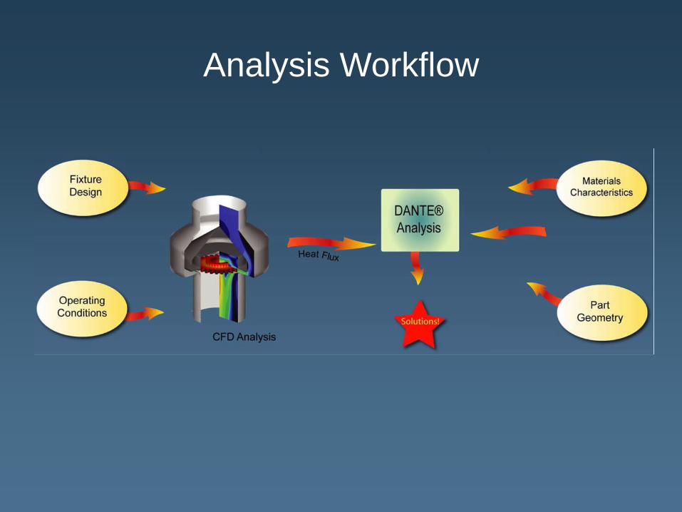
Analysis Workflow

Fixture Design
Quench flow is radially inward toward the gear teeth to provide the best quenching to the wear surfaces.
Water flow rate: 500 GPM

CFD Goal
Provide accurate surface heat flux rates for use in FEA (DANTE) modeling
ChallengesFull transient 3D simulation of real geometries would take too long to be a practical engineering tool
How do heat fluxes vary in space in time?
Investigate with 2D model
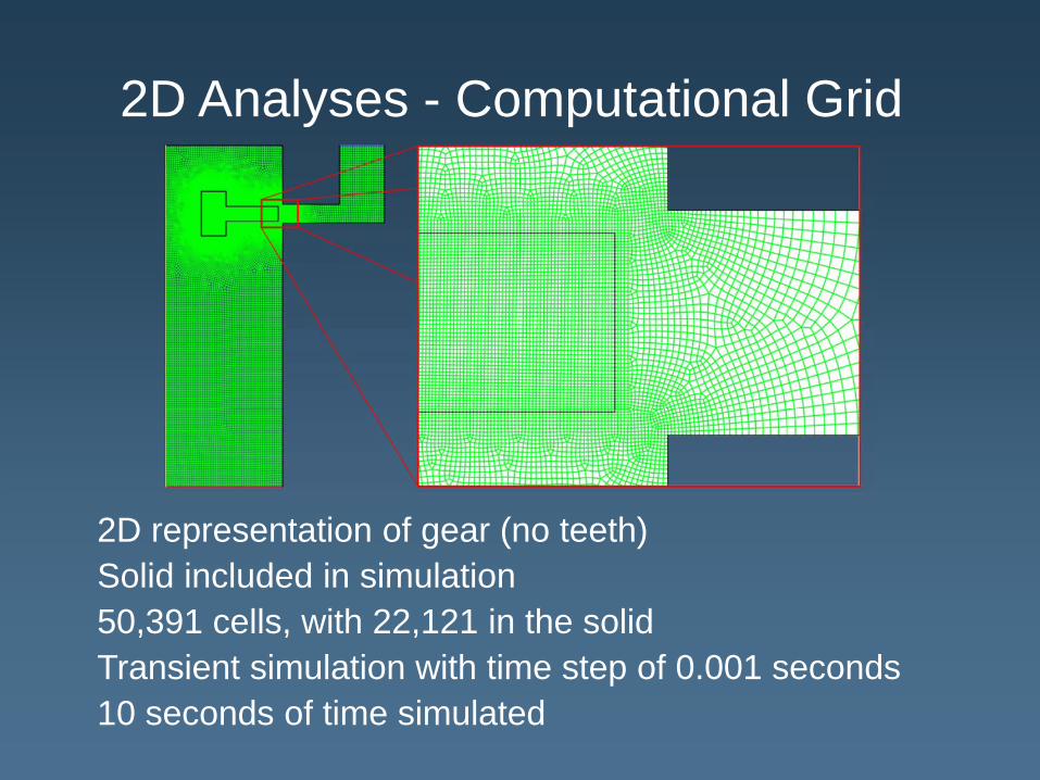
2D Analyses - Computational Grid
2D representation of gear (no teeth)Solid included in simulation50,391 cells, with 22,121 in the solidTransient simulation with time step of 0.001 seconds10 seconds of time simulated

2D Analyses - Flow Field
Impingement on gear tooth face provides good heat transfer
High velocity around “corners” of gear disk also provide high heat transfer
Asymmetry on top and bottom corners
Velocities on faces of gear disk are lower
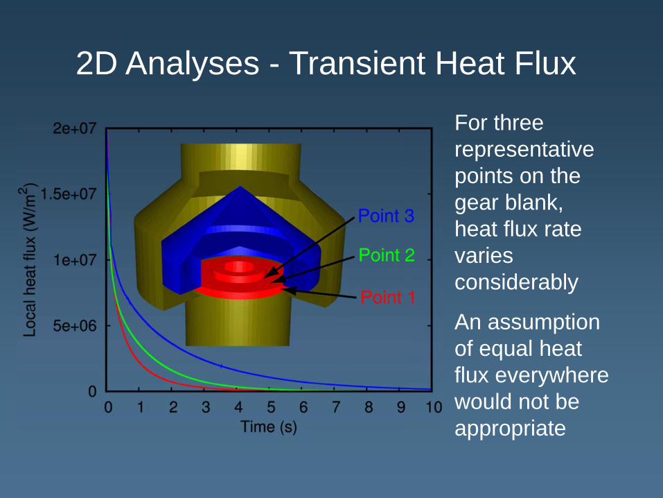
2D Analyses - Transient Heat Flux
For three representativepoints on the gear blank, heat flux rate variesconsiderably
An assumption of equal heat flux everywhere would not be appropriate
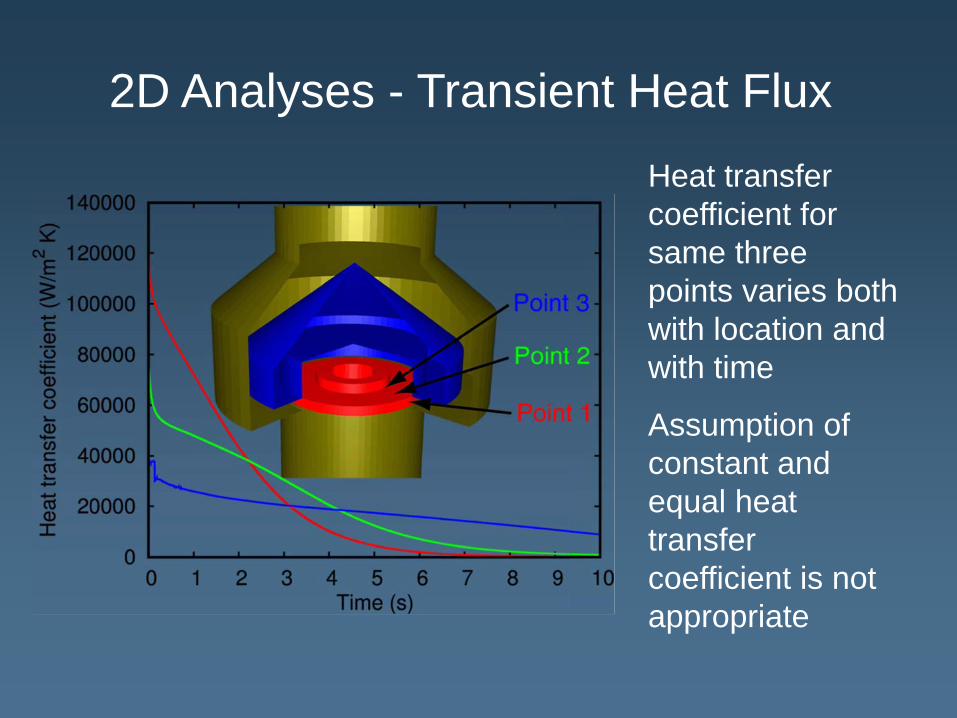
2D Analyses - Transient Heat FluxHeat transfer coefficient for same three points varies both with location and with time
Assumption of constant and equal heat transfercoefficient is not appropriate
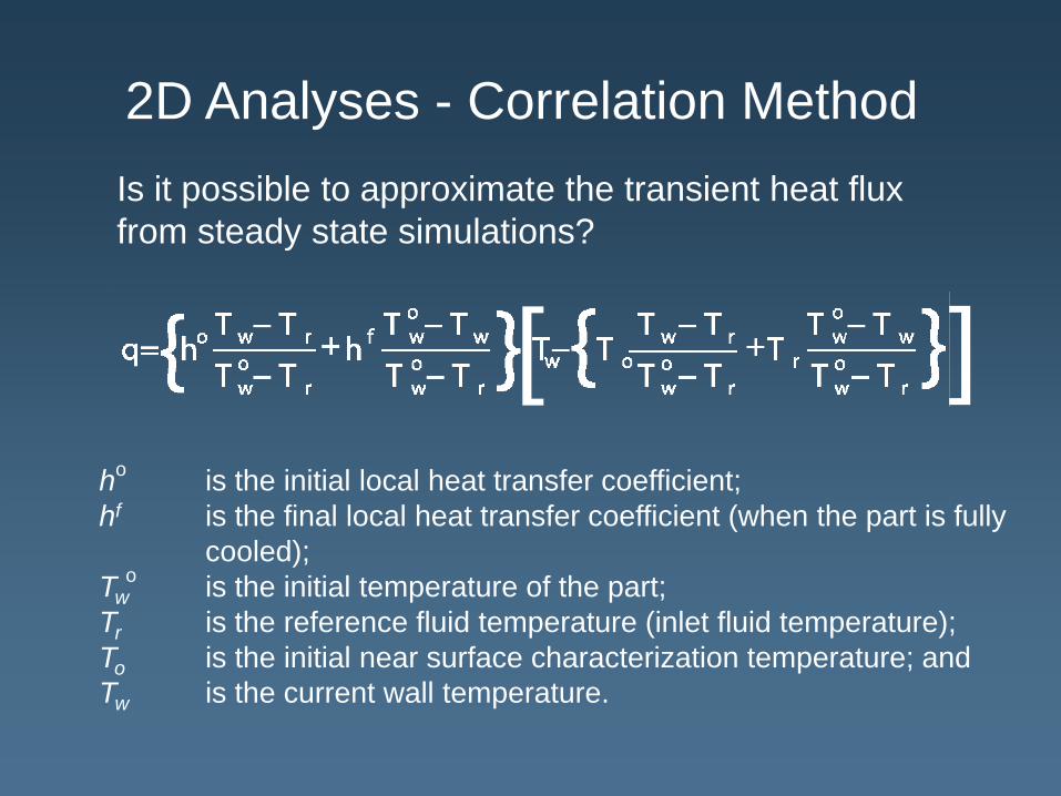
2D Analyses - Correlation MethodIs it possible to approximate the transient heat flux from steady state simulations?
ho is the initial local heat transfer coefficient; hf is the final local heat transfer coefficient (when the part is fully
cooled);Tw is the initial temperature of the part; Tr is the reference fluid temperature (inlet fluid temperature); To is the initial near surface characterization temperature; and Tw is the current wall temperature.
o
[ ]
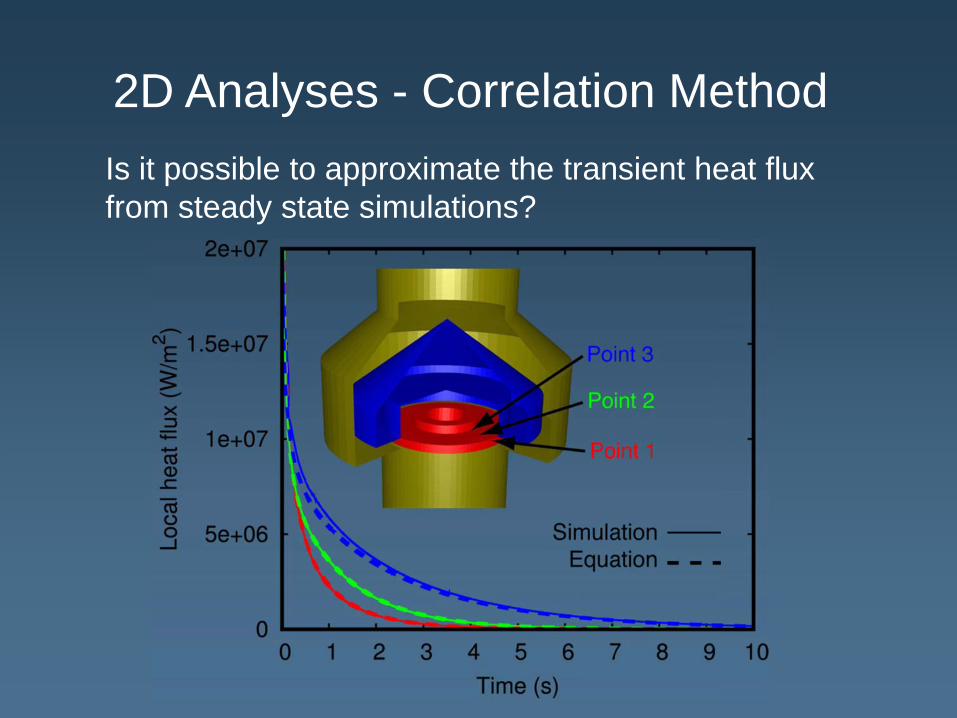
2D Analyses - Correlation MethodIs it possible to approximate the transient heat flux from steady state simulations?

3D Analyses - Computational Grid
1,721,070computationalcells (fluid only)
Gear surface temperature held constant
Hot surface and ambient surface simulations made
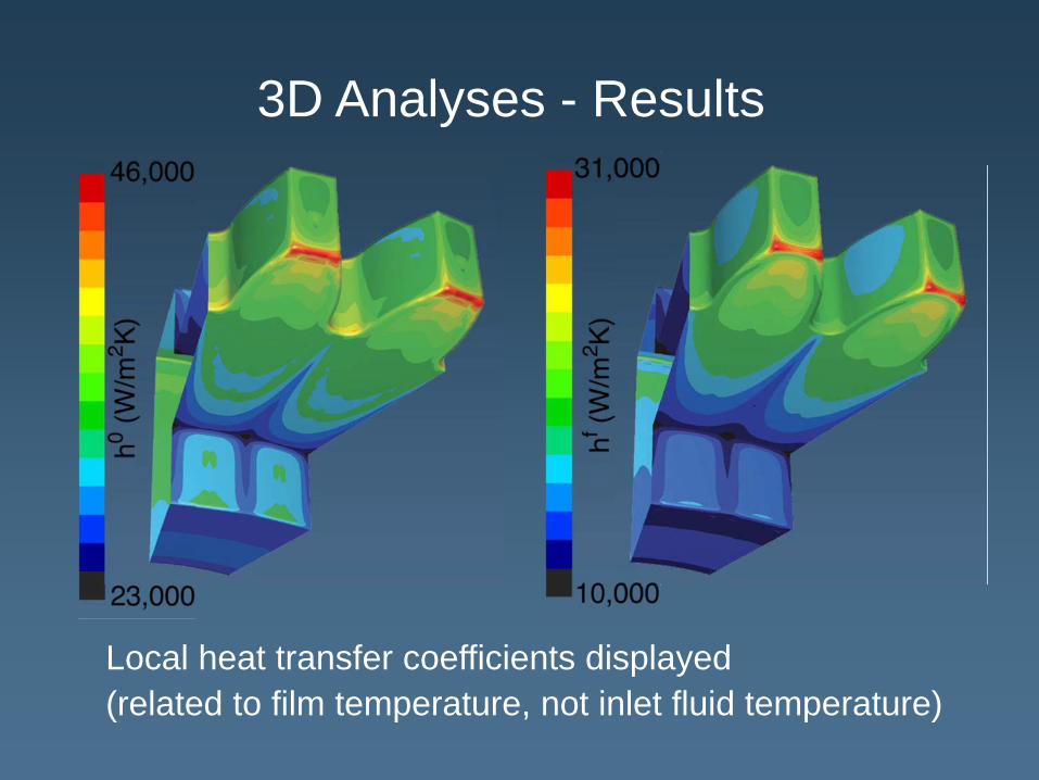
3D Analyses - Results
Local heat transfer coefficients displayed(related to film temperature, not inlet fluid temperature)
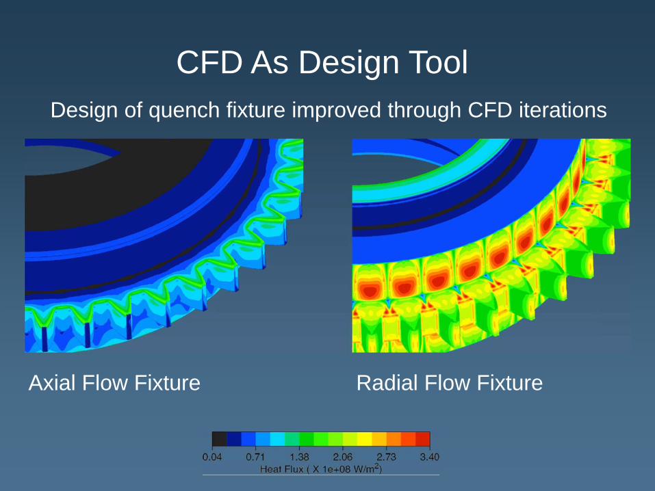
CFD As Design ToolDesign of quench fixture improved through CFD iterations
Axial Flow Fixture Radial Flow Fixture

Interface with DANTE
Computational grids for CFD and DANTE do not necessarily match
Data exported for each gear surface node in the CFD model, including position, and three governing parameters
Data are interpolated by DANTE boundary condition routine
At each time step, the current local wall temperature is used to compute the wall heat flux
[ ]

DANTE Finite Element Meshing3D single gear tooth model
– Material: Pyro53
– Fine surface elements are used to more accurately catch the thermal and carbon gradients in the surface
– Cyclic boundary condition is applied
5959 nodes
4820 elements
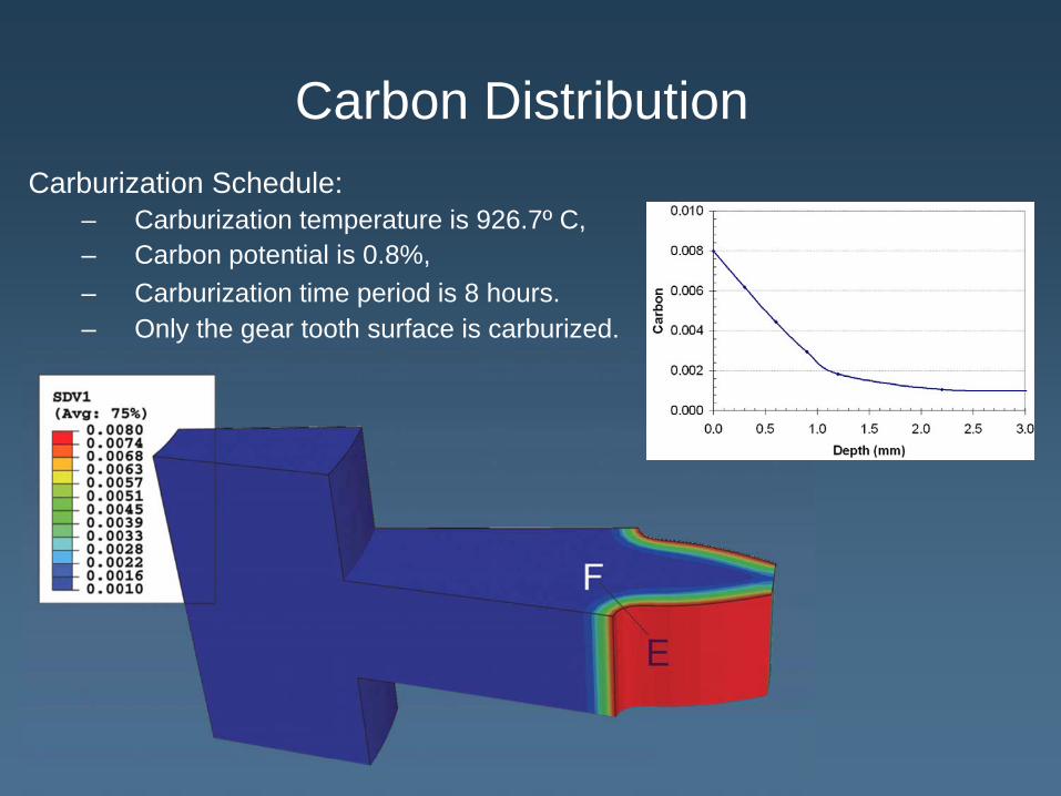
Carbon DistributionCarburization Schedule:
– Carburization temperature is 926.7º C,– Carbon potential is 0.8%,– Carburization time period is 8 hours.– Only the gear tooth surface is carburized.

Temperature During Quenching
1 2
3 4

5 6
7 8
Temperature During Quenching (cont.)
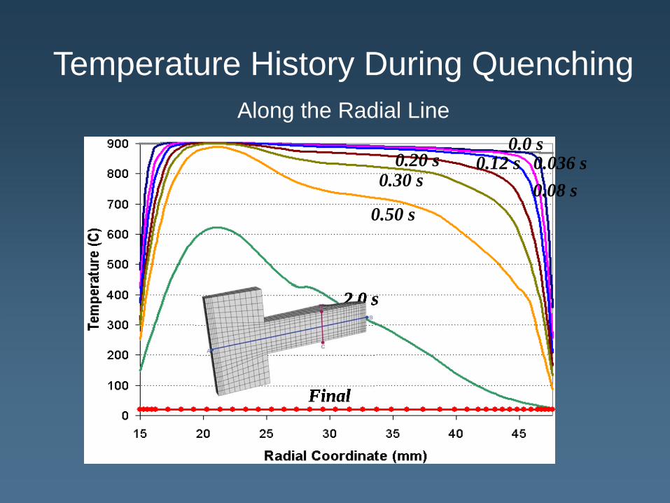
Temperature History During Quenching Along the Radial Line
0.0 s0.036 s0.08 s
0.12 s0.20 s0.30 s
0.50 s
2.0 s
Final
2.0 s
Final
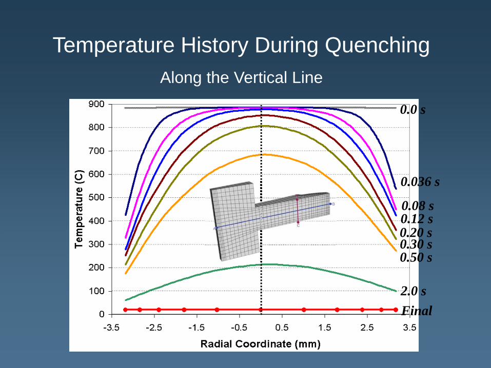
Temperature History During Quenching Along the Vertical Line
0.0 s
0.036 s
0.08 s0.12 s0.20 s0.30 s0.50 s
2.0 sFinal
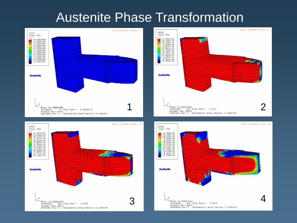
1
Austenite Phase Transformation
2
3 4
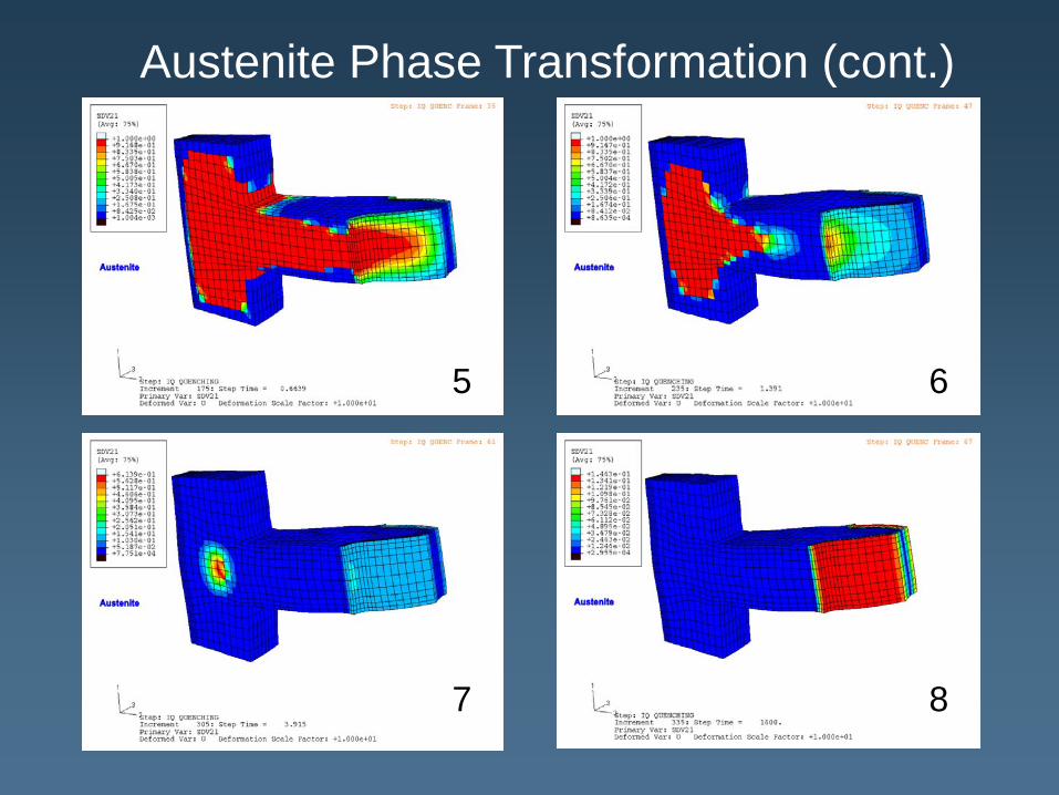
Austenite Phase Transformation (cont.)
5 6
7 8

0.12 s
0.20 s
0.30 s0.50 s
Phase History During Quenching Along the Radial Line
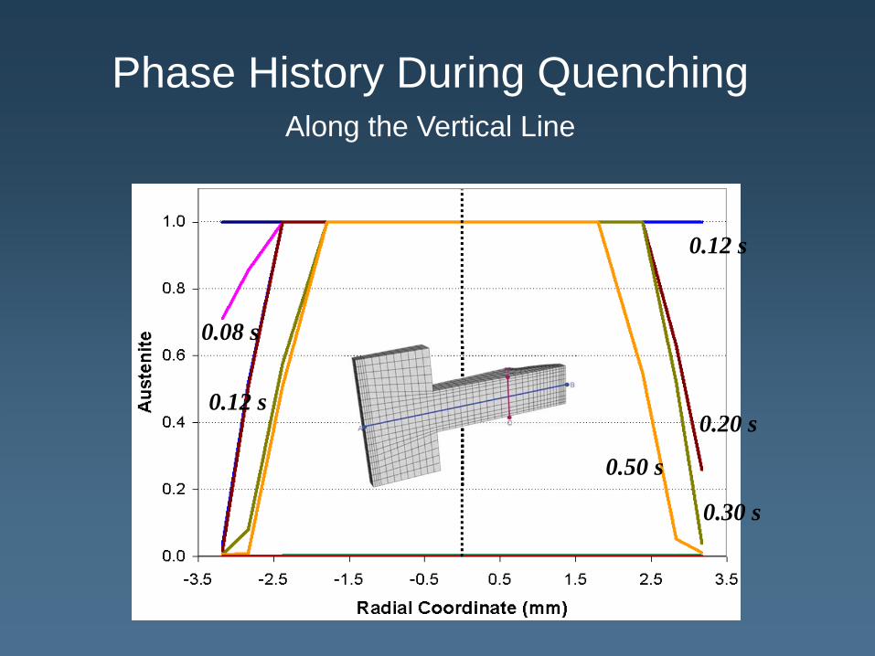
Phase History During Quenching Along the Vertical Line
0.50 s
0.30 s
0.20 s
0.08 s
0.12 s
0.12 s

Hoop Stress Evolution
1 2
3 4
1
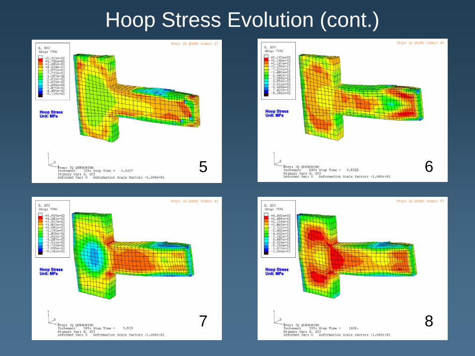
Hoop Stress Evolution (cont.)
5 6
7 8
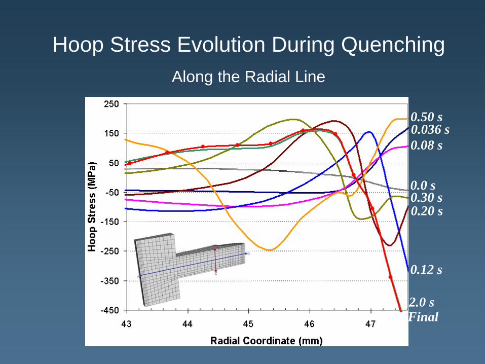
0.0 s
0.036 s0.08 s
0.12 s
0.20 s0.30 s
0.50 s
2.0 sFinal
Hoop Stress Evolution During Quenching Along the Radial Line

Axial Displacement During Quenching
1 2
3 4
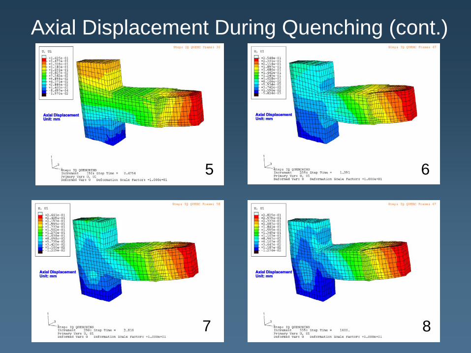
Axial Displacement During Quenching (cont.)
5 6
7 8
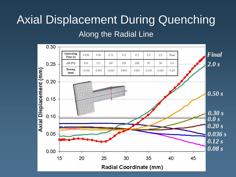
Axial Displacement During Quenching Along the Radial Line
0.0 s
0.036 s
0.08 s0.12 s
0.20 s
0.30 s
0.50 s
2.0 sFinal
Summary & ConclusionsA method was developed to closely predict the transient 3D surface heat fluxes from a pair of steady-state CFD analyses.
Those heat fluxes were supplied to a DANTE model for a more complete analysis of the quenching process.
The DANTE results show that inclusion of the CFD predicted heat flux rates has a significant effect on distortion, compared to the assumption of constant heat transfer coefficient.
A combination of CFD and DANTE provides more accuracy of the simulations.
Acknowledgments
This work was conducted under the Cooperative Agreement No. W15QKN-06-2-0105 between the Edison Materials Technology Center and the US Army Benet Laboratories. DCT and ASC would also like to acknowledge the contributions of IQ Technologies Inc. and NexTec Corp. to this project.