Embed Size (px)
Citation preview

lable at ScienceDirect
Applied Thermal Engineering 66 (2014) 423e434
Contents lists avai
Applied Thermal Engineering
journal homepage: www.elsevier .com/locate/apthermeng
A novel approach to hot oil system design for energy conservation
Abtin Ataei a,d, Nassim Tahouni b,*, Seyed Masoud Haji Seyedi a, Seyed Majid Hashemian c,ChangKyoo Yoo d, M. Hassan Panjeshahi b,e
aGraduate School of the Environment and Energy, Science and Research Branch, Islamic Azad University, Tehran, Iranb School of Chemical Engineering, College of Engineering, University of Tehran, Tehran, IrancDepartment of Mechanical Engineering, Shahrood University of Technology, Shahrood, IrandDepartment of Environmental Science & Engineering, Green Energy Center/Center for Environmental Studies, Kyung Hee University, Yongin, South KoreaeDepartment of Chemical and Petroleum Engineering, University of Calgary, Calgary, Alberta, Canada
h i g h l i g h t s
� A new design method was developed for hot oil system by changing arrangement of HEN.� Hot oil is supplied to a network of heater with a parallel/series configuration.� Better hot oil generator performance and increased heating capacity was achieved.� Debottlenecking procedures for the design of hot oil systems was developed.
a r t i c l e i n f o
Article history:Received 6 October 2013Accepted 22 January 2014Available online 31 January 2014
Keywords:Hot oil systemHot oil generatorHot oil networkHeat exchanger networkDebottlenecking
* Corresponding author. Tel.: þ98 21 6695 7788; faE-mail addresses: [email protected] (N. Taho
(M.H. Panjeshahi).
http://dx.doi.org/10.1016/j.applthermaleng.2014.01.041359-4311/� 2014 Elsevier Ltd. All rights reserved.
a b s t r a c t
In this paper, a new systematic design methodology was developed for hot oil system by changingarrangement of heat exchanger network from parallel to mixed series/parallel. In re-circulating hot oilsystems, hot oil from the hot oil generator is supplied to a network of heaters that usually has a parallelconfiguration. However, re-use of hot oil between different heating duties enables hot oil networks to bedesigned with series arrangements. This allows better hot oil generator performance and increasedheating capacity, both in the context of new design and retrofit. First, the hot oil generator and the hot oilnetwork were examined separately, in order to discuss the nature of hot oil system design. A model ofhot oil systems was then developed to examine the performance of the hot oil generator to recirculationflow rate and return temperature, as well as to predict heating efficiency. In second step, the design ofthe overall hot oil system was developed by investigating the interactions between the hot oil networkdesign and the hot oil generator performance. Debottlenecking procedures for the design of hot oilsystems was also developed.
� 2014 Elsevier Ltd. All rights reserved.
1. Introduction
Hot water heaters, steam heaters, and recirculating hot oil sys-tems are all used to supply the required heat to a process [1]. Ofthese methods, recirculating hot oil systems are by far the mostcommon today, as they do not have a drum to supply latent heat,and they are able not only to conserve process water and steam, butalso to reduce energy and capital cost, compared to hot water andsteam heater systems [2e4].
x: þ98 21 6695 7784.uni), [email protected]
4
Hot oil heating is a type of indirect heating in which a liquidphase heat transfermedium is heated and circulated to one ormoreheat energy users within a closed loop system. Mineral oil,pressure-less synthetic oil and pressurized synthetic oil are com-mon heat transfer mediums [4]. Main suppliers of hot oil packagesand plants such as Sigma Thermal [4], Gaumer Process [5], Chro-malox [6], Thermal Fluid Systems [7] and GTS Energy [8] offer thosesystems at up to 420 �C to be used to heat revolving rolls, platens,molds, jacketed tanks and autoclaves in petrochemical, chemicaland pulp-and-paper plants. The general specifications of hot oilsystems offered by Chromalox� are given in Table 1 [6].
However, no attention has been placed on the interactions be-tween hot oil generator and heat exchanger networks [9,10], eventhough changes to operating conditions of hot oil systems

Table 1General specifications of hot oil systems offered by Chromalox� [6].
Model System type Application Operatingtemperature (�C)
Mbha
CMXO Heat transfernon-pressurized
Synthetic oil 10e290 20.4e81.9
COS Heat transfernon-pressurized
Synthetic oil 10e330 30.7e1365
PFC Heat transfernon-pressurized
Synthetic oil 10e315 30.7e2047
CLD Heat transferpressurized
Synthetic oil 10e400 30.7e2047
CLS Heat transferpressurized
Syltherm� 800 40e400 30.7e2047
OMHTS Heat transfermultiple zone
Synthetic oil 10e400 30.7e4094
CHTV Heat transfervaporizer
Dowtherm�
Therminol��30 to 400 51.2e1024
a Mbh is the ASME & ANSI standard for one thousand British Thermal Units perhour.
A. Ataei et al. / Applied Thermal Engineering 66 (2014) 423e434424
frequently occur in industrial sites. Design and operating problemsof hot oil generators have been the focus of attention on the part ofmanufacturers and process engineers. Mitra [10] represented thedesign considerations of hot oil systems and sizing of equipment.Mukherjee [11] addressed some techniques for improving theperformance of the individual components in hot oil systems.Arnold [12] developed a differential equation model to do adetailed thermal analysis for a hot oil system in different temper-ature ranges. Ennis [13] discussed some of the key safety design andoperational aspects of hot oil systems. Probert [14] presented amethod for designing and rating of hot oil storage tanks. Halttunen[15] addressed amethod to analysis energy costs of hot oil pumpingsystems. Wallace et al. [16] designed a new method for hot oilintegration with a heat recovery system generator. Policastro [17]suggested an advanced, flexible control system for hot oil plants.Colaco and Floyd [18] developed a computerized method to docontrol and analysis of conditions of a hot oil system on a dynamicbasis. Gu and Liu [19] presented an analysis on the flow process ofhot oil in the organic heat transfer material heater based on finitetime thermodynamics. Hlozek and Bardov [20] designed a hot oilsystem to do waste heat recovery from reciprocating gas engines.Nasir et al. [21] designed a hot oil system to utilize the turbinewaste heat to generate electric power in a Neptune plant. Mosta-jeran Goortani et al. [22] introduced a hot oil system to recover theheat from stack gases and distribute it to the appropriate coldstreams in a Kraft mill plant. Ohm et al. [23] described a dryingtechnique for the upgrading of crushed low-rank coal utilizing a hotoil system. Singhmaneeskulchai et al. [24] studied on dynamic datareconciliation of a utility heat exchanger using hot oil from a wasteheat recovery unit as a hot stream to heat up ethane product as acold process stream from a natural gas separation plant.
However, to date, research on heating systems have focused onthe individual components [10], and not on the system as a whole.Because of the interactions between hot oil networks and hot oilgenerator performance, all of the heating system componentsshould be considered when designing and operating these systems.Process integration method can be applied to address the in-teractions between the components of hot oil systems. ProcessIntegration is a family of methodologies for combining several partsof processes or whole processes to reduce the consumption of re-sources [25]. This methodology examines the potential forimproving and optimizing the heat exchange between heat sourcesand sinks in order to conserve energy, reduce costs and emissions[25,26]. Klemes et al. [25] represented the recent developments inprocess integration.
Various process integration approaches have been developedover the past two decades to study energy systems with the goal ofidentifying energy recovery opportunities in process industries.Thermal pinch analysis, which was developed for the analysis andoptimization of heat exchanger networks, seems to be the mostcommonly used heat integration method [27]. Thermal pinchanalysis was introduced by Linnhoff and Flower [28]. This analysiswas expanded and widely publicized by Linnhoff and Hindmarsh[29], Smith [30,31], Kemp [32] and Gundersen [33].The mass pinchanalysis was introduced by El-Halwagi and Manousiouthakis [34].This analysis was applied in the area of wastewater minimizationby Wang and Smith [35,36]. This method was widely expanded byMann and Liu [37], Prakash and Shenoy [38] and Wan Alwi andManan [39]. The mass and thermal pinch analyses were combinedtogether by Savulescu et al. [40], Panjeshahi et al. [41,42], Ahme-tovíc and Kravanja [43,44] to identify opportunities to simulta-neously reduce the water and energy consumption in industrialfacilities.
Consider some of the possible changes to an existing hot oilsystem. A new heat exchanger might be introduced into the heatexchanger network, or the heat duty of heaters changed, or processchanges might change the operating conditions. These processchanges influence the conditions of the hot oil return and, conse-quently, affect the performance of the hot oil generator. In suchsituations, it is often not clear how the system will be affected bythe newconditions or how the hot oil network designwill affect theheating system. As such, a combined thermal and mass pinchanalysis should be used to investigate the interactions for theoverall system.
In this paper, we present a systematic method for the design ofhot oil systems that accounts for these interactions and processconstraints, based on a combination of thermal and mass pinchanalyses. First, the hot oil generator and the hot oil network will beexamined separately, in order to discuss the nature of hot oil systemdesign. Amodel of hot oil systemswill be developed to examine theperformance of the hot oil generator to recirculation flow rate andreturn temperature, as well as to predict heating efficiency. Amethodology for hot oil network design will then be developed,assuming fixed inlet and outlet conditions for the hot oil. Finally,the design of the overall hot oil system will be developed byinvestigating the interactions between the hot oil network designand the hot oil generator performance [45]. Debottlenecking pro-cedures for the design of hot oil systems will also be developed. Insummary, moving from parallel to series arrangements for hot oilnetworks:
� Increases the efficiency of the hot oil system,� Decreases the temperature differences in the hot oil heatexchangers.
2. Design of hot oil networks
The current practice for hot oil network design most often usesparallel configurations [4,10,46], whereby hot oil is supplieddirectly to individual heat exchangers. After the hot oil has beenused in each heat exchanger, the cold oil returns to the hot oilgenerator (Fig. 1a). The minimum hot oil demand is determined byminimizing the flow rate to the individual heat exchangers (Fig.1b).Under a parallel arrangement [47], return hot oil flow rate andtemperature become maximized, leading to poor generator per-formance [45].
Thus far, no systematic methods have been suggested fordealing with the design of hot oil networks, and the traditionalparallel design is not flexible when dealing with various process

Fig. 1. Parallel configuration of hot oil networks.
A. Ataei et al. / Applied Thermal Engineering 66 (2014) 423e434 425
restrictions. Therefore, a new hot oil network design methodologywill now be developed.
Not all heating duties require hot oil at the hot oil supply tem-perature, which allows us, if appropriate, to change the hot oilnetwork from a parallel to a series design. A series arrangement, inwhich hot oil is reused in the network, returns the hot oil at a lowertemperature and flow rate. From the predictions of the model, theheat supplied by this hot oil generator can be expected to increaseunder these conditions. In other words, if the design configurationis converted from parallel to series arrangements [48], the hot oilgenerator can service a higher heat load for the heaters.
2.1. New design methodology for hot oil networks
A simple problem (Example 1) will be used to develop thedesign methodology for hot oil networks. The hot oil system inExample 1 has four heat exchangers that use hot oil as the heatingmedium for cold process streams. The temperature, flow rate, andheating duty of the cold process streams are shown in Table 2. Theoperating data was given from an actual plant. The data for coldprocess streams are represented as CP values, which is the productof specific heat capacity and flow rate. It is assumed that the heatcapacity of hot oil is constant throughout the temperature range.The parallel configuration hot oil network in Example 1 has inletand outlet CPs of 28.69 kW/�C and outlet temperature of 181.46 �C.The non-pressurized synthetic oil supplied by Chromalox� [6] isselected for this plant. According to Table 1 and Fig. 2, the model ofthat type of hot oil is COS [6]. The maximum operating oil tem-perature for this type of hot oil is 330 �C. Therefore, the maximumhot oil inlet temperature is 320 �C, taking into account the necessityof a 10 �C safety margin.
To develop a systematic method for the design of such systems,some clues can be taken from water pinch analysis [49] anddeveloped for hot oil network design. In hot oil network analysis, itis assumed that any hot oil-using operation can be represented as acounter-current heat exchange operation with a minimum tem-perature difference (Fig. 3). As seen in Fig. 3, the hot oil inlet tem-perature to each heat exchanger should be between the maximum
Table 2Cold process stream data of hot oil networks: Example 1.
Heatexchanger
Inlet streamtemperature (�C)
Outlet streamtemperature (�C)
CP (kW/�C) Totalload (kW)
1 230 310 10 8002 230 250 25 5003 95 250 10 15504 95 170 15 1125
hot oil supply temperature (320 �C) and the temperature of theoutlet cold process stream from that heat exchanger plus DTmin. Thehot oil outlet temperature from each heat exchanger must be be-tween the temperature of the inlet cold process stream to each heatexchanger plus DTmin and theminimum hot oil return temperature.The concept of the limiting hot oil profile is taken fromwater pinchanalysis and shown in Fig. 4; it is defined here as theminimum inletand outlet temperatures for the hot oil stream. As seen in Fig. 4, thehot oil supply line touches the composite curve at 240 �C where thepinch point is defined. It means the hot oil supplied by generatorshould be directly sent to the heat exchangers which need the oilhotter than 240 �C (above the pinch) and the outlet oil streamsmaybe reused in other heat exchangers (below the pinch).
As seen, these allowable temperatures are limited by the mini-mum temperature difference (DTmin). In a new design, this could bethe practical minimum temperature difference for a given type ofheat exchanger. In retrofitting, the temperature difference could bechosen to comply with the performance limitations of an existingheat exchanger under revised operating conditions of reducedtemperature differences and increased flow rate. In addition, thelimiting hot oil profile might be determined by other processconstraints, such as corrosion, fouling, maximum allowable oiltemperature, etc. Any hot oil line at or above this profile isconsidered a feasible design. The limiting profile is used to define aboundary between feasible and infeasible regions. The limiting hotoil profile allows the individual streams of the hot oil network to berepresented on a common basis, as hot oil and energy character-istics are represented simultaneously. It should be emphasized thatthe final design will not necessarily feature the minimum tem-perature difference incorporated in the limiting data. It simplyrepresents a boundary between feasible and infeasible conditions.Most heaters in the final network design will feature temperature-driving forces greater than those used for the specification oflimiting conditions.
This study focuses primarily on retrofit design and, therefore,restricts consideration to deal only with cold streams to be heatedby hot oil. A better design for hot oil networks will be exploitedunder a fixed heat exchanger network configuration. For a grassrootdesign, the design of hot oil networks and heat exchanger networksshould be addressed simultaneously. In this paper, the topology ofthe heat exchanger network is assumed to be fixed. The duties ofthe hot and cold streams in the heat exchanger network are, thus,assumed to be unrelated to the heating system. In other words, thestreams heated by the hot oil do not affect other streams in the heatexchanger network.
As the inlet temperature of hot oil to heaters is decreased, thedriving force for the heat exchangers is decreased, and additionalheat exchanger area might be required. At the same time, however,
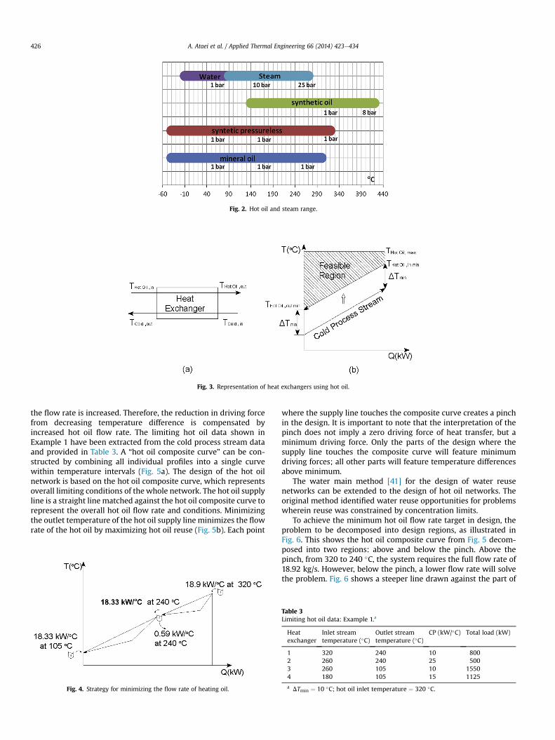
Fig. 2. Hot oil and steam range.
Fig. 3. Representation of heat exchangers using hot oil.
A. Ataei et al. / Applied Thermal Engineering 66 (2014) 423e434426
the flow rate is increased. Therefore, the reduction in driving forcefrom decreasing temperature difference is compensated byincreased hot oil flow rate. The limiting hot oil data shown inExample 1 have been extracted from the cold process stream dataand provided in Table 3. A “hot oil composite curve” can be con-structed by combining all individual profiles into a single curvewithin temperature intervals (Fig. 5a). The design of the hot oilnetwork is based on the hot oil composite curve, which representsoverall limiting conditions of the whole network. The hot oil supplyline is a straight line matched against the hot oil composite curve torepresent the overall hot oil flow rate and conditions. Minimizingthe outlet temperature of the hot oil supply line minimizes the flowrate of the hot oil by maximizing hot oil reuse (Fig. 5b). Each point
Fig. 4. Strategy for minimizing the flow rate of heating oil.
where the supply line touches the composite curve creates a pinchin the design. It is important to note that the interpretation of thepinch does not imply a zero driving force of heat transfer, but aminimum driving force. Only the parts of the design where thesupply line touches the composite curve will feature minimumdriving forces; all other parts will feature temperature differencesabove minimum.
The water main method [41] for the design of water reusenetworks can be extended to the design of hot oil networks. Theoriginal method identified water reuse opportunities for problemswherein reuse was constrained by concentration limits.
To achieve the minimum hot oil flow rate target in design, theproblem to be decomposed into design regions, as illustrated inFig. 6. This shows the hot oil composite curve from Fig. 5 decom-posed into two regions: above and below the pinch. Above thepinch, from 320 to 240 �C, the system requires the full flow rate of18.92 kg/s. However, below the pinch, a lower flow rate will solvethe problem. Fig. 6 shows a steeper line drawn against the part of
Table 3Limiting hot oil data: Example 1.a
Heatexchanger
Inlet streamtemperature (�C)
Outlet streamtemperature (�C)
CP (kW/�C) Total load (kW)
1 320 240 10 8002 260 240 25 5003 260 105 10 15504 180 105 15 1125
a DTmin ¼ 10 �C; hot oil inlet temperature ¼ 320 �C.

Fig. 5. Hot oil composite curve and targeting for maximum reuse.
A. Ataei et al. / Applied Thermal Engineering 66 (2014) 423e434 427
the problem below the pinch. Of the CP of 18.92 kW/�C from the hotoil, after use up to the pinch condition of 240 �C, only a CP of18.33 kW/�C is used, and the balance (CP ¼ 0.59 kW/�C) is returneddirectly to the hot oil furnace. In this way, each part of the problemonly uses the minimum amount of hot oil. However, it should againbe noted that, in minimizing the amount of hot oil used, the tem-perature differences in the heater are also minimized, leading totradeoffs between the designs of the hot oil system and the heatexchangers.
As shown in Fig. 6, three hot oil mains are conceptualized: one atthe supply temperature of 320 �C, a second at the pinch tempera-ture of 240 �C, and a third at 105 �C, the minimum temperatureallowable in the system. The flow rate of hot oil required in each ofthe mains is shown at the top of the main. The flow rate to bereturned to the hot oil furnace from each of the mains is shown atthe bottom of the main. The heating streams are superimposedonto the hot oil mains at their appropriate temperatures. In Fig. 6,Stream 1, which starts at 320 �C and terminates at 240 �C, is shownbetween the 320 �C and 240 �C hot oil mains. Stream 2 starts at260 �C, between the first two hot oil mains. Stream 3 starts at260 �C, again between the first two hot oil mains. However, in thiscase, Stream 3 terminates at the minimum temperature of 105 �C.Initially, therefore, it is broken into two parts, each within theappropriate design region. Finally, Stream 4 starts at 180 �C belowthe pinch oil mains and finishes at the105 �C hot oil main. Thestreams are then connected to the appropriate hot oil main, tosatisfy the individual heating requirement. This provides an initialdesign for the hot oil network to meet the target requirements.
However, the design has not yet been completed, as there is afundamental difficulty with the arrangement shown in Fig. 6.Stream 3 requires a change in flow rate at the pinch hot oil main
Fig. 6. Completed hot oil design grid.
(240 �C), which means that the heating duty corresponding withStream 3 would have to be broken down into two heat exchangers,each being supplied with different flow rates. The change in flowrate for Stream 3 is, in fact, easily removed. Consider Fig. 7, whichshows the temperature vs. heat duty for an operationwith a changein flow rate, as in the case of Stream 3 in Fig. 6. A heat balancearound Part 1 in Fig. 7 gives (assuming the specific heat capacity ofthe hot oil to be constant):
F1ðTPinch � T1Þ ¼ F2�TPinch � Tin;Max
�(1)
Moving the mixing junction to the inlet of the operation, asshown in Fig. 7, and carrying out a heat balance at the new mixingjunction, gives [42]:
Tin ¼ ððF2 � F1Þ*TPinchÞ þ ðF1*T1ÞF2
¼ TPinch � ðF1*ðTPinch � T1ÞÞF2
(2)
Substituting Equation (1) into Equation (2) gives:
Tin ¼ ðF2*TPinchÞ � ðF2*ðTPinch � Tin:MaxÞÞF2
¼ Tin;min (3)
In other words, if the mixing junction is moved from the middleto the beginning of the operation, there is a constant flow ratethroughout the operation that correspondswith theminimum inlettemperature after mixing.
Fig. 8 shows the corresponding grid diagram to correct thechange in flow rate. The change in flow rate for Stream 3 thatpreviously occurred at the pinch temperature mains is now addedfrom the pinch temperature mains to the inlet of Stream 3. Thisprovides a design for the hot oil network that achieves the targetminimum flow rate of CP ¼ 18.92 kW/�C. The arrangement shownin Fig. 8 involves reuse of hot oil from Streams 1 and 2 into Streams3 and 4 via a hot oil main at pinch temperature 240 �C. An alter-native way to arrange the design is to make the connection directly,rather than through intermediate hot oil main. If the intermediatehot oil main is removed, then there are basically two sources of hotoil from Streams 1 and 2 at 240 �C and two sinks for hot oil inStreams 3 and 4 at 240 �C. These sources and sinks can be con-nected together in different ways. If the intermediate hot oil mainat 240 �C is removed from the design, then the streams can beconnected directly together. Fig. 9 shows a flow sheet for onepossible arrangement. In Fig. 9, there is reuse from Heat Exchanger1 to Heat Exchanger 3 and from Heat Exchanger 2 to HeatExchanger 4. Some of the hot oil from the furnace goes throughHeat Exchanger 1, and some bypasses it, to be mixed in beforeentering Heat Exchanger 3. This step is necessary to comply withthe inlet constraints for Heat Exchanger 3. The flow sheet in Fig. 9,then, needs to be assessed for its practicality and operability; the

Fig. 7. Changing the mixing arrangement can avoid a change in hot oil flow rate.
A. Ataei et al. / Applied Thermal Engineering 66 (2014) 423e434428
design can then be evolved. For example, the bypass around HeatExchanger 1 in Fig. 9 can be eliminated, and all of theCP ¼ 12.67 kW/�C can be put through Heat Exchanger 1 beforeentering Heat Exchanger 3. In the design, the essential feature forachieving the target is the reuse of hot oil between exchangers.Different arrangements than the one shown in Fig. 10 are possiblefor achieving the target by connecting the sources and sinks at240 �C differently.
Parallel hot oil use that is minimized to achieve DTmin at theoutlet of each heat exchanger leads to a flow rate for the network of9.66 kg/s, with a hot oil return temperature of 181.3 �C. Maximizingthe reuse reduces this flow rate to 6.39 kg/s, and the hot oil returntemperature decreases to 110 �C (Table 4).
A number of complications are likely to be encountered, whichneed to be addressed:
a) One complication that can occur is that the number of designregions can be greater than two. Fig. 10 shows a design probleminvolving just two design regions: below the pinch and abovethe pinch. The hot oil composite curve in Fig. 10 has three designregions, rather than two. The design regions are identified bydrawing straight lines between the extreme convex points of the
Fig. 8. Final grid design after changing the mixing arrangement to avoid flow ratechanges.
hot oil composite curve, as illustrated in Fig. 10. If more designregions exist, additional hot oil mains are required. However, theprocedure is, basically, the same as in the example describedabove, taking into account the additional mains.
b) Furthermore, if the hot oil supply line does not correspond withthe minimum flow rate because of system interactions or tem-perature constraints for dew point 130 �C (assuming DT ¼ 30 �Cfor flue gas and hot oil, exhaust temperature of flue gas will be160 �C), then a pinch point is not created with the limiting hotoil composite curve, no pinch means that the temperaturedriving force is negative and is not acceptable (Fig. 11a). Thesetting could be between minimum flow rate (maximum reuse)and no reuse (parallel arrangement), as shown in Fig.11a. The oil
Fig. 9. Flow sheet of hot oil network with maximum reuse of hot oil.
Fig. 10. More complex problems might require a greater number of hot oil mains.
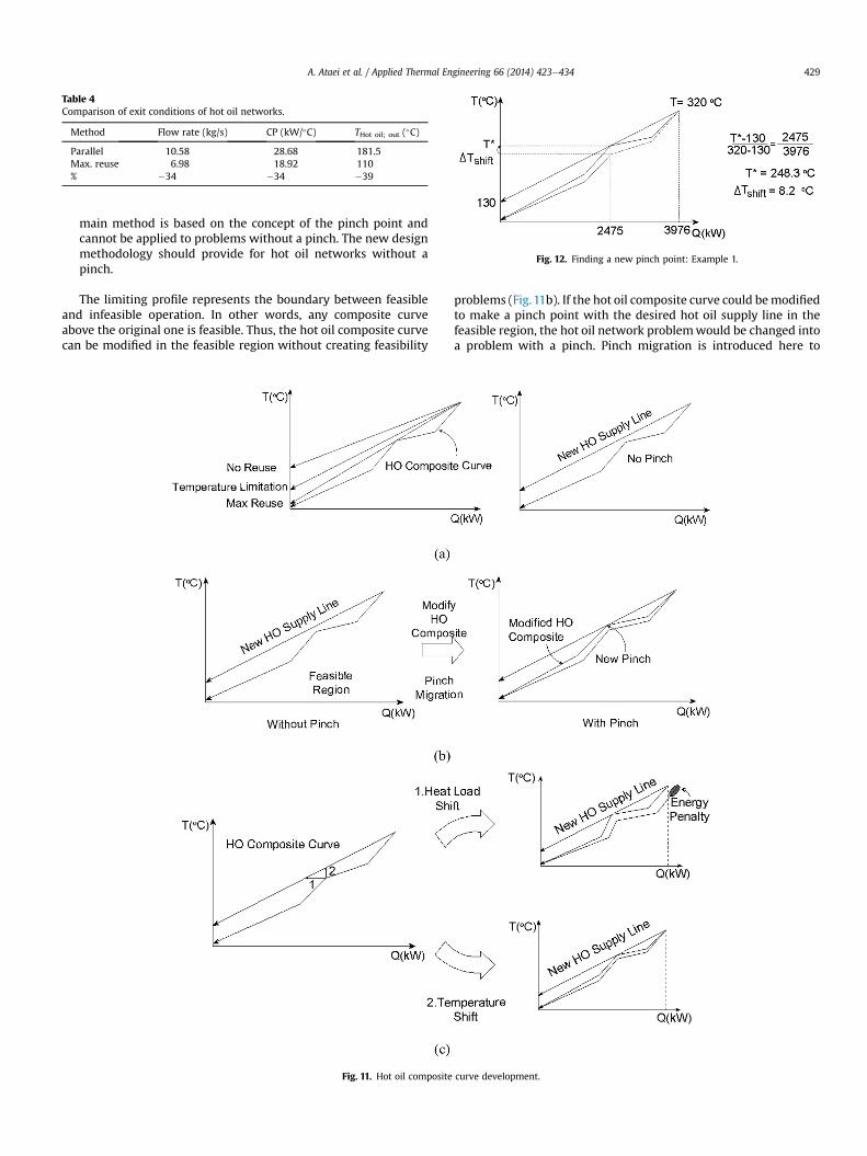
Table 4Comparison of exit conditions of hot oil networks.
Method Flow rate (kg/s) CP (kW/�C) THot oil; out (�C)
Parallel 10.58 28.68 181.5Max. reuse 6.98 18.92 110% �34 �34 �39
Fig. 12. Finding a new pinch point: Example 1.
A. Ataei et al. / Applied Thermal Engineering 66 (2014) 423e434 429
main method is based on the concept of the pinch point andcannot be applied to problems without a pinch. The new designmethodology should provide for hot oil networks without apinch.
The limiting profile represents the boundary between feasibleand infeasible operation. In other words, any composite curveabove the original one is feasible. Thus, the hot oil composite curvecan be modified in the feasible region without creating feasibility
Fig. 11. Hot oil composite
problems (Fig.11b). If the hot oil composite curve could bemodifiedto make a pinch point with the desired hot oil supply line in thefeasible region, the hot oil network problemwould be changed intoa problem with a pinch. Pinch migration is introduced here to
curve development.

Fig. 13. Pinch migration and temperature shift: Example 1.
A. Ataei et al. / Applied Thermal Engineering 66 (2014) 423e434430
convert problems without a pinch into those with a pinch with thedesired supply line (Fig. 11b).
Two approaches to pinch migration can be adopted (Fig. 11c).The first is to shift heat load, in which the hot oil composite curvemoves along the heat load axis. The second is temperature shift, inwhich the hot oil composite curve moves along the temperatureaxis. In the two approaches, temperature shift is adopted, becauseheat load shift would result in an energy penalty.
The next problem is how to find the new pinch and how tomodify the composite curve with a temperature shift. Let usintroduce a target temperature of 130 �C for the hot oil for Example1. A new pinch is created between the modified composite curveand the new supply line, which is calculated from a simple heatbalance (Fig. 12). The new calculated pinch of 248.3 �C is migratedfrom the original pinch of 240 �C. It is necessary for individualduties to apply a temperature shift for modification of the com-posite curve. Hot oil Streams 1, 2, and 3 take part in creating theoriginal pinch, which means Streams 1, 2, and 3 are the candidatesfor temperature shift.
The limiting hot oil modifications occur in two stages. The firststage is to shift the temperature of the limiting hot oil profiles ac-cording to the value of the temperature shift (8.3 �C in thisexample). Modified profiles might cross the supply line, thusrequiring another step. The second stage is to increase the flow rateof the limiting hot oil profile when the shifted profile is restrictedby temperature limitations. The limiting hot oil profile is modifiedto satisfy temperature limitations by increasing the hot oil flow rateCP.
In Example 1, Streams 2 and 3 can be modified to obtain newlimiting hot oil data simply by shifting temperatures. However, forStream 1, it is necessary to increase flow rate, because the 20 �C hotoil supply temperature restricts the temperature shift of the
Table 5Temperature-shifted limiting hot oil data.
Heatexchanger
Inlet streamtemperature (�C)
Outlet streamtemperature (�C)
CP (kW/�C) Total load (kW)
1a 320 248.3 11.15 8002a 268.3 248.3 25 5003a 268.3 113.3 10 15504 180 105 15 1125
a Modified data.
limiting data. The heat balance equations determine the increasedflow rate and the new limiting exit temperature [31].
CPnew ¼ CPold ToldPinch � ToldHO;in
TnewPinch � TnewHO;in
!(4)
TnewHO;in ¼ CPold ToldHO;out � ToldHO;in
CPnew
!(5)
After modification of the conditions for each individual heatexchanger, the modified hot oil profiles are as shown in Fig. 13, andthe new limiting hot oil data are as shown in Table 5. For Stream 1,the CP is increased from 10 to 11.18 kW/�C, as a result of the secondstage modification. The new composite curve is constructed bycombining all modified limiting profiles. The modified hot oilcomposite now creates a pinch point with the desired hot oil supplyline. The hot oil network design can now be carried out using thehot oil mains method. The resulting design is shown in Fig. 14. Thehot oil generator return temperature and flow rate agree with thetarget.
The pinch migration and temperature shift method enablescreation of a design with any target temperature. The hot oilnetwork will have different configurations with different targettemperatures, which can be seen by comparing the maximumreuse design (Fig. 9) with the design with a temperature constraint(Fig. 14). The pumping load and operating cost of the base and newdesign method are given in Table 6.
Fig. 14. Hot oil network design without a pinch.
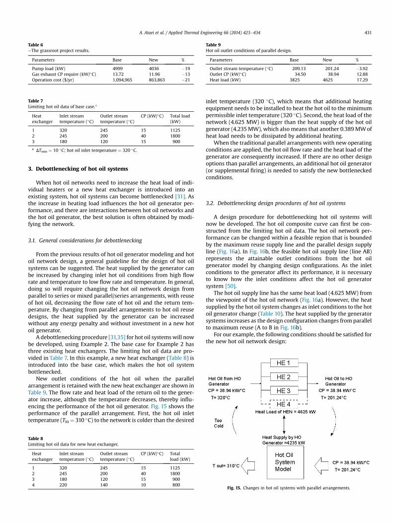
Table 6eThe grassroot project results.
Parameters Base New %
Pump load (kW) 4999 4036 �19Gas exhaust CP require (kW/�C) 13.72 11.96 �13Operation cost ($/yr) 1,094,965 863,863 �21
Table 7Limiting hot oil data of base case.a
Heatexchanger
Inlet streamtemperature (�C)
Outlet streamtemperature (�C)
CP (kW/�C) Total load(kW)
1 320 245 15 11252 245 200 40 18003 180 120 15 900
a DTmin ¼ 10 �C; hot oil inlet temperature ¼ 320 �C.
Table 9Hot oil outlet conditions of parallel design.
Parameters Base New %
Outlet stream temperature (�C) 209.13 201.24 �3.92Outlet CP (kW/�C) 34.50 38.94 12.88Heat load (kW) 3825 4625 17.29
A. Ataei et al. / Applied Thermal Engineering 66 (2014) 423e434 431
3. Debottlenecking of hot oil systems
When hot oil networks need to increase the heat load of indi-vidual heaters or a new heat exchanger is introduced into anexisting system, hot oil systems can become bottlenecked [31]. Asthe increase in heating load influences the hot oil generator per-formance, and there are interactions between hot oil networks andthe hot oil generator, the best solution is often obtained by modi-fying the network.
3.1. General considerations for debottlenecking
From the previous results of hot oil generator modeling and hotoil network design, a general guideline for the design of hot oilsystems can be suggested. The heat supplied by the generator canbe increased by changing inlet hot oil conditions from high flowrate and temperature to low flow rate and temperature. In general,doing so will require changing the hot oil network design fromparallel to series or mixed parallel/series arrangements, with reuseof hot oil, decreasing the flow rate of hot oil and the return tem-perature. By changing from parallel arrangements to hot oil reusedesigns, the heat supplied by the generator can be increasedwithout any energy penalty and without investment in a new hotoil generator.
A debottlenecking procedure [31,35] for hot oil systemswill nowbe developed, using Example 2. The base case for Example 2 hasthree existing heat exchangers. The limiting hot oil data are pro-vided in Table 7. In this example, a new heat exchanger (Table 8) isintroduced into the base case, which makes the hot oil systembottlenecked.
New outlet conditions of the hot oil when the parallelarrangement is retained with the new heat exchanger are shown inTable 9. The flow rate and heat load of the return oil to the gener-ator increase, although the temperature decreases, thereby influ-encing the performance of the hot oil generator. Fig. 15 shows theperformance of the parallel arrangement. First, the hot oil inlettemperature (Tin¼ 310 �C) to the network is colder than the desired
Table 8Limiting hot oil data for new heat exchanger.
Heatexchanger
Inlet streamtemperature (�C)
Outlet streamtemperature (�C)
CP (kW/�C) Totalload (kW)
1 320 245 15 11252 245 200 40 18003 180 120 15 9004 220 140 10 800
inlet temperature (320 �C), which means that additional heatingequipment needs to be installed to heat the hot oil to the minimumpermissible inlet temperature (320 �C). Second, the heat load of thenetwork (4.625 MW) is bigger than the heat supply of the hot oilgenerator (4.235MW), which alsomeans that another 0.389MWofheat load needs to be dissipated by additional heating.
When the traditional parallel arrangements with new operatingconditions are applied, the hot oil flow rate and the heat load of thegenerator are consequently increased. If there are no other designoptions than parallel arrangements, an additional hot oil generator(or supplemental firing) is needed to satisfy the new bottleneckedconditions.
3.2. Debottlenecking design procedures of hot oil systems
A design procedure for debottlenecking hot oil systems willnow be developed. The hot oil composite curve can first be con-structed from the limiting hot oil data. The hot oil network per-formance can be changed within a feasible region that is boundedby the maximum reuse supply line and the parallel design supplyline (Fig. 16a). In Fig. 16b, the feasible hot oil supply line (line AB)represents the attainable outlet conditions from the hot oilgenerator model by changing design configurations. As the inletconditions to the generator affect its performance, it is necessaryto know how the inlet conditions affect the hot oil generatorsystem [50].
The hot oil supply line has the same heat load (4.625 MW) fromthe viewpoint of the hot oil network (Fig. 16a). However, the heatsupplied by the hot oil system changes as inlet conditions to the hotoil generator change (Table 10). The heat supplied by the generatorsystems increases as the design configuration changes from parallelto maximum reuse (A to B in Fig. 16b).
For our example, the following conditions should be satisfied forthe new hot oil network design:
Fig. 15. Changes in hot oil systems with parallel arrangements.

Fig. 16. Hot oil supply line targeting.
A. Ataei et al. / Applied Thermal Engineering 66 (2014) 423e434432
(1) The inlet temperature to the hot oil network should be320 �C.
(2) The heat supplied by the hot oil generator system should beequal to the heat load of the hot oil network.
In this example, it is not necessary to achieve a temperaturehigher than 320 �C. As can be seen in Table 8, the target conditionslie somewhere along the feasible hot oil supply line.
The next stage is to find the target supply conditions for the hotoil generator. The feasible hot oil supply line can move from BN toBM in Fig. 16b. The target conditions, which satisfy the desiredtemperature to hot oil network (320 �C), are found by changing thehot oil supply conditions from BN to BM. The heat removal of theheating system is the same as the heat load of the hot oil network atthe target conditions (B*), where the inlet temperature to the hot oilnetwork is satisfied. Target conditions are given by the intersection
Table 10-Effects of hot oil inlet conditions.
Case Heat removal case ofhot oil system (MW)
Parallel (A) 4.235Maximum reuse (B) 4.685Target 4.625
between the feasible hot oil supply line and the isothermal line ofthe heating system outlet temperature.
The target conditions for debottlenecking have been found byusing the heating system model. The target conditions are a CP of28.3 kW/�C and a temperature of 156 �C. At target conditions, theheating demands of the networks are satisfied without additionalheating capacity. Below the target temperature, the current heatingsystems cannot operate up to heating demand. The next stage is todesign the hot oil network with target conditions. As the new hotoil supply line has no pinch with the limiting composite curve, thetemperature shift and pinch migration method is applied, asexplained in the previous section. The new pinch point is calcu-lated, and the limiting hot oil profile is modified (Fig. 17). The finaldesign for the debottlenecked hot oil system is shown in Fig. 18.
The suggested method for hot oil network design is based on aconceptual design methodology and, therefore, other design con-figurations can evolve. The design complexity can be reduced forthe sake of simplicity, but this would likely result in a heatingsystem performance penalty. The design of hot oil systems involvestradeoffs, including hot oil generator costs, pressure drops, pipingcosts, design complexity, etc. An optimizationmethod is required tomake the tradeoffs in a structured way; this issue will be theobjective of future work.
The proposed debottlenecking procedure enables the hot oilgenerator to manage the increased heat load by changing the
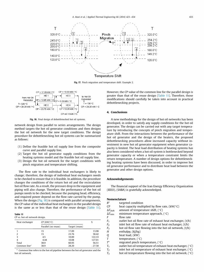
Fig. 17. Pinch migration and temperature shift: Example 2.
Fig. 18. Final design of debottlenecked hot oil systems.
A. Ataei et al. / Applied Thermal Engineering 66 (2014) 423e434 433
network design from parallel to series arrangements. The designmethod targets the hot oil generator conditions and then designsthe hot oil network for the new target conditions. The designprocedure for debottlenecking hot oil systems can be summarizedas follows:
(1) Define the feasible hot oil supply line from the compositecurve and parallel supply line.
(2) Target the hot oil generator supply conditions from theheating systems model and the feasible hot oil supply line.
(3) Design the hot oil network for the target conditions withpinch migration and temperature shifting.
The flow rate to the individual heat exchangers is likely tochange; therefore, the design of individual heat exchangers needsto be checked to ensure that it is feasible. In addition, the procedurechanges the conditions of the return hot oil and the recirculationhot oil flow rate. As a result, the pressure drop in the equipment andpiping will also change. Therefore, the performance of the hot oilpumps needs to be checked, because the pumping head, efficiency,and required power depend on the flow rate carried by the pump.When the design (Fig. 18) is compared with parallel arrangements,the CP value of the individual heat exchangers in the parallel designis the same as or less than that of the reuse design (Table 11).
Table 11CP vs. hot oil network design.
Heat exchanger CP (kW/�C) %
Parallel (no reuse) Target (reuse)
1 15 17.09 13.982 15 23.76 58.423 4.5 10.00 122.334 4.44 10.08 127.01Total 38.9 60.95 56.51Common linea 38.9 28.20 �27.58
a Common line refers to the hot oil pipeline between the hot oil generator and thehot oil network.
However, the CP value of the common line for the parallel design isgreater than that of the reuse design (Table 11). Therefore, thosemodifications should carefully be taken into account in practicaldebottlenecking projects.
4. Conclusions
A new methodology for the design of hot oil networks has beendeveloped, in order to satisfy any supply conditions for the hot oilgenerator. The design can be carried out with any target tempera-ture by introducing the concepts of pinch migration and temper-ature shift. From the interactions between the performance of thehot oil generator and the design of the heaters, the proposeddebottlenecking procedures allow increased capacity without in-vestment in new hot oil generator equipment when generator ca-pacity is limited. The heat load distribution of heating systems hasalso been considered when a hot oil system is bottlenecked beyondgenerator capacity or when a temperature constraint limits thereturn temperature. A number of design options for debottleneck-ing heating systems have been discussed, in order to improve hotoil generator performance and to distribute heat load between thegenerator and other design options.
Acknowledgements
The financial support of the Iran Energy Efficiency Organization(IEEO), (SABA) is gratefully acknowledged.
NomenclatureB* targeted conditionCP heat capacity multiplied by flow rate, (kW/�C)DTshift amount of temperature shift, (�C)DTmin minimum temperature approach, (�C)F flow rateF1 outlet hot oil flow rate of exhaust heat exchanger, (t/h)F2 inlet hot oil flow rate of exhaust heat exchanger, (t/h)F3 hot oil flow rate flowing into the hot oil network, (t/h)H enthalpy, (kJ/kg)Q heat load, (kW)T temperature, (�C)T* migrated pinch temperature, (�C)T1 outlet hot oil temperature of exhaust heat exchanger, (�C)T2 inlet hot oil temperature of exhaust heat exchanger, (�C)T3 hot oil temperature flowing into the hot oil network, (�C)

A. Ataei et al. / Applied Thermal Engineering 66 (2014) 423e434434
SubscriptsCold cold process stream in heat exchangerin inlet conditionsMax maximumMin minimumout outlet conditionsP pinch point
SuperscriptsHE process/hot oil heat exchangerHEN heat exchanger networkHO hot oilNew migrated pinch pointOld original pinch point
References
[1] A. Ataei, K.S. Lee, J.J. Lim, M.J. Kim, H.B. Liu, O.Y. Kang, T.S. Oh, C.K. Yoo,A review on environmental process engineering, Int. J. Environ. Res. 5 (4)(2011) 875e890.
[2] A. Ataei, Application of combined pinch and exergy analysis in retrofit of anolefin plant for energy conservation, Sci. Res. Essays 6 (12) (2011) 2437e2446.
[3] A. Ataei, C.K. Yoo, Combined pinch and exergy analysis for energy efficiencyoptimization in a steam power plant, Int. J. Phys. Sci. 5 (7) (2010) 1110e1123.
[4] Sigma Thermal, Thermal Oil Heating Systems, 2013. www.sigmathermal.com(accessed 12.12.13).
[5] Gaumer Process, Gaumer Hot Oil Systems, 2013. www.gaumer.com (accessed12.12.13).
[6] Chromalox, Hot Oil Heaters e Heat Transfer Systems, 2013. www.chromalox.com (accessed 12.12.13).
[7] Thermal Fluid Systems, Hot Oil Heating Systems, 2013. www.tfsheat.com(accessed 12.12.13).
[8] GTS Energy, Thermal Fluid Heaters, 2013. www.gtsenergy.com (accessed12.12.13).
[9] A. Ataei, C.K. Yoo, Application of pinch technology for waste heat recovery inthe linear-alkyl-benzene sulfonation process, Asian J. Chem. 23 (4) (2011)1539e1547.
[10] S. Mitra, Design Considerations of Hot Oil System, 2013. www.academia.edu/1514808/design_consideration_of_hot_oil_system (accessed 07.06.13).
[11] R. Mukherjee, Role of optimal heat exchange in chemical plant energy con-servation, Chem. Eng. World 19 (10) (1984) 47e49.
[12] F.G. Arnold, Thermal analysis of hot oiling, Am. Soc. Mech. Eng. (1990) 4. PET1,Energy-Sources Technology Conference and Exhibition, New Orleans, LA, USA,14 January 1990 through 18 January 1990.
[13] T. Ennis, Safety in design of thermal fluid heat transfer systems, Inst. Chem. E155 (2009) 162e169, 21st Institution of Chemical Engineers Symposium onHazards 2009 e Hazards XXI: Process Safety and Environmental Protection,Manchester, United Kingdom, 10 November 2009 through 12 November2009.
[14] D. Probert, Design and performance of hot-oil storage tanks, Appl. Energy 1(4) (1975) 247e278.
[15] O.H. Halttunen, Analyzing energy costs of hot oil pumping systems e com-parison of centrifugal, canned-motor, and seal-free magnetic drive pumps,Plant Eng. 32 (10) (1978) 155e161.
[16] P.S. Wallace, K.A. Johnson, J.L. Kasbaum, Hot Oil Integration with Heat Re-covery System Generator and Method of Operation, US Patent 6,606,862,2003.
[17] E.F. Policastro, Hot oil, cool control, InTech 55 (4) (2008) 24e25.[18] R.J. Colaco, M.C. Floyd, Supervisory operation and data system controls hot oil
pipeline, Oil Gas J. 74 (9) (1976) 87e90.[19] W. Gu, Y. Liu, Analysis on the flow process of hot oil in the organic heat
transfer material heater based on finite time thermodynamics, Adv. Mater.Res. 250e253 (2011) 2979e2983, 1st International Conference on Civil En-gineering, Architecture and Building Materials, CEABM 2011, Haikou, China,18 June 2011 through 20 June 2011.
[20] R.J. Hlozek, J.B. Bardov, Waste heat recovery from reciprocating gas engines:glycol regeneration, in: Proceedings, Annual Convention e Gas ProcessorsAssociation, 1980, pp. 100e104. Proc Annu Conv Gas Process Assoc Tech Pap59th, Houston, TX, USA, 17 March 1980 through 19 March 1980.
[21] P. Nasir, S. Jones, D. Schochet, D. Posner, Utilization of turbine waste heat togenerate electric power at Neptune plant, in: GPA Annual Convention Pro-ceedings, 2004, p. 9. Gas Processors Association e 83rd Annual Convention
Proceedings 2004: Linking Energy Partners for the Future, New Orleans, LA,United States, 14 March 2004 through 17 March 2004.
[22] B. Mostajeran Goortani, E. Mateos-Espejel, M. Moshkelani, J. Paris, Energyefficiency improvement of a Kraft process through practical stack gases heatrecovery, Appl. Therm. Eng. 31 (2011) 4091e4096.
[23] T.I. Ohm, J.S. Chae, J.H. Lim, S.H. Moon, Evaluation of a hot oil immersiondrying method for the upgrading of crushed low-rank coal, J. Mech. Sci.Technol. 26 (4) (2012) 1299e1303.
[24] P. Singhmaneeskulchai, N. Angsutorn, K. Siemanond, Dynamic data reconcil-iation in a hot-oil heat exchanger for validating energy consumption, Chem.Eng. Trans. 35 (2013) 493e498, http://dx.doi.org/10.3303/CET1335082.
[25] J.J. Klemes, P.S. Varbanov, Z. Kravanja, Recent developments in process inte-gration, Chem. Eng. Res. Des. 91 (2013) 2037e2053.
[26] B. Bakhtiari, S. Bedard, Retrofitting heat exchanger networks using a modifiednetwork pinch approach, Appl. Therm. Eng. 51 (2013) 973e979.
[27] R.F. Dunn, M.M. El-Halwagi, Review process integration technology review:background and applications in the chemical process industry, J. Chem.Technol. Biotechnol. 78 (2003) 1011e1021, http://dx.doi.org/10.1002/jctb.738.
[28] B. Linnhoff, J.R. Flower, Synthesis of heat exchanger networks: I. Systematicgeneration of energy optimal networks, AIChE J. 24 (4) (1978) 633e642.
[29] B. Linnhoff, E. Hindmarsh, The pinch design method for heat exchanger net-works, Chem. Eng. Sci. 38 (1983) 745e763.
[30] R. Smith, Chemical Process Design, McGraw-Hill, New York, USA, 1995.[31] R. Smith, Chemical Process Design and Integration, John Wiley & Sons, UK,
2005.[32] I.C. Kemp, Pinch Analysis and Process Integration, a User Guide on Process
Integration for Efficient Use of Energy, Elsevier, Amsterdam, The Netherlands,2007.
[33] T. Gundersen, Heat Integration: Targets and Heat Exchanger Network Design(Chapter 4), in: J.J. Kleme�s (Ed.), Handbook of Process Integration (PI): Mini-misation of Energy and Water Use, Waste Emissions, Woodhead Publishing,Cambridge, UK, 2013.
[34] M.M. El-Halwagi, V. Manousiouthakis, Synthesis of mass-exchange networks,AIChE J. 35 (1989) 1233e1244. http://dx.doi.org/10.1002/aic.690350802.
[35] Y.P. Wang, R. Smith, Wastewater minimisation, Chem. Eng. Sci. 49 (7) (1994)981e1006.
[36] Y.P. Wang, R. Smith, Waste-water minimisation with flow-rate constraints,Chem. Eng. Res. Des. 73 (8) (1995) 889e904.
[37] J.G. Mann, Y.A. Liu, Industrial Water Reuse and Wastewater Minimization,McGraw Hill, New York, USA, 1999, ISBN 0071348557.
[38] R. Prakash, U.V. Shenoy, Targeting and design of water networks for fixedflowrate and fixed contaminant load operations, Chem. Eng. Sci. 60 (1) (2005)255e268.
[39] S.R. Wan Alwi, Z.A. Manan, Water pinch analysis for water management andminimisation: an introduction, in: Kleme�s (Ed.), Process Integration Hand-book, Woodhead Publishing, Cambridge, UK, 2013, ISBN 978 0 85709 593 0.http://dx.doi.org/10.1533/9780857097255.3.353.
[40] L.E. Savulescu, M. Sorin, R. Smith, Direct and indirect heat transfer in waternetwork systems, Appl. Therm. Eng. 22 (8) (2002) 981e988.
[41] M.H. Panjeshahi, A. Ataei, M. Gharaie, R. Parand, Optimum design of coolingwater systems for energy and water conservation, Chem. Eng. Res. Des. 87 (2)(2009) 200e209.
[42] M.H. Panjeshahi, M. Gharaie, A. Ataei, Debottlenecking procedure of effluentthermal treatment system, Energy 35 (2010) 5202e5208.
[43] E. Ahmetovíc, Z. Kravanja, Simultaneous synthesis of process water and heatexchanger networks, Energy 57 (2013) 236e250.
[44] E. Ahmetovíc, Z. Kravanja, Simultaneous optimization of heat-integratedwater networks involving process-to-process streams for heat integration,Appl. Therm. Eng. 62 (1) (2014) 302e317. http://dx.doi.org/10.1016/j.applthermaleng.2013.06.010.
[45] B. Galan, I.E. Grossman, Optimal design of distributed wastewater treatmentnetworks, Ind. Eng. Chem. Res. 37 (10) (1998) 4036e4048.
[46] A. Azhdari, H. Ghadamian, A. Ataei, C.K. Yoo, A new approach for optimizationof combined heat and power generation in edible oil plants, J. Appl. Sci. 9 (21)(2009) 3813e3820.
[47] M.M. El-Halwagi, A.M. El-Halwagi, V. Manousiouthakis, Optimal design ofdephenolization networks for petroleum-refinery wastes, Trans. IChemE (PartB) 70 (1992) 131e139.
[48] J.K. Kim, R. Smith, Cooling water system design, Chem. Eng. Sci. 56 (12) (2001)3641e3658.
[49] W.J. Kuo, R. Smith, Effluent treatment system design, Chem. Eng. Sci. 52 (23)(1997) 4273e4290.
[50] C.K. Yoo, A. Ataei, Y.S. Kim, M.J. Kim, H.B. Liu, J.J. Lim, Environmental systemsengineering: a state of the art review, Sci. Res. Essays 5 (17) (2010) 2341e2357.


![Failure of periodonta] treatment · Periodontics Failure of periodonta] treatment Klaus H.Rateiischak'^ Treatment faihires appear to occur mare frequently in pcriodontology than in](https://img.pdfslide.us/doc/110x75/5ed56b59d241fc22bf7bc0f9/failure-of-periodonta-treatment-periodontics-failure-of-periodonta-treatment-klaus.jpg)