Embed Size (px)
Citation preview

SC I ENCE ADVANCES | R E S EARCH ART I C L E
APPL I ED SC I ENCES AND ENG INEER ING
1Computer Science and Artificial Intelligence Laboratory, Massachusetts Instituteof Technology, Cambridge, MA 02139, USA. 2Electrical Engineering and ComputerScience Department, Massachusetts Institute of Technology, Cambridge, MA02139, USA. 3University of Grenoble Alpes, Inria, LJK, 38000 Grenoble, France.*Corresponding author. Email: [email protected]
Sundaram et al., Sci. Adv. 2019;5 : eaaw1160 12 July 2019
Copyright © 2019
The Authors, some
rights reserved;
exclusive licensee
American Association
for the Advancement
of Science. No claim to
originalU.S. Government
Works. Distributed
under a Creative
Commons Attribution
NonCommercial
License 4.0 (CC BY-NC).
Dow
nload
Topology optimization and 3D printing of multimaterialmagnetic actuators and displaysSubramanian Sundaram1,2*, Melina Skouras1,3, David S. Kim1,Louise van den Heuvel1, Wojciech Matusik1,2
Upcoming actuation systemswill be required to performmultiple tightly coupled functions analogous to theirnatural counterparts; e.g., the ability to control displacements and high-resolution appearance simultaneously isnecessary for mimicking the camouflage seen in cuttlefish. Creating integrated actuation systems is challengingowing to the combined complexity of generating high-dimensional designs and developing multifunctionalmaterials and their associated fabrication processes. Here, we present a complete toolkit consisting of multiob-jective topology optimization (for design synthesis) andmultimaterial drop-on-demand three-dimensional printingfor fabricating complex actuators (>106 design dimensions). The actuators consist of soft and rigid polymersand a magnetic nanoparticle/polymer composite that responds to a magnetic field. The topology optimizerassigns materials for individual voxels (volume elements) while simultaneously optimizing for physical deflectionandhigh-resolution appearance. Unifying a topology optimization-based design strategy with amultimaterialfabrication process enables the creation of complex actuators and provides a promising route toward automated,goal-driven fabrication.
ed
on January 6, 2020http://advances.sciencemag.org/
from
INTRODUCTIONActuators for modern-day robots increasingly need to integrate multiplefunctions together inside a single package to simultaneously optimizefor weight, power efficiency, topology, size, and other performancemet-rics. This idea is central to proposals that advocate a tight integration ofsensing, actuation, and computation inside robotic materials (1), wherethe distinction betweenmaterials andmachines is blurred (2). This newparadigm requires robot parts to be designed formultiple functions andoptimized for multiple objectives as seen in natural organisms. Thechallenge in reproducing these biomimetic multifunctional systems isexplicitly evident in the design of actuation systems. A classic exampleis the actuation system in cuttlefish that controls both the physical de-flections (papillae in the skin) and the high-resolution appearance(multilayermetachrosis). Controlling these two abilities (physical defor-mation and appearance control) simultaneously is essential for effectivecamouflage (3–5). Reproducing such seamlessly integrated actuationsystems that optimize for multiple objectives is challenging due to thecomplexity that exists in (i) designing in a high-dimensional designspace (withmany design variables) while optimizing formultiple objec-tives and (ii) fabricating these designs with new materials and in free-form geometries.
Many examples of contemporary actuation systems of high com-plexity consist of microscale actuators tiled into regular arrays. Thedigital micromirror device (6) withmillions of identical actuators (7)and the “millipede,” a high-density data storage system consisting ofmicroelectromechanical system cantilevers (1024-element actuatorarray) (8), are two impressive examples. However, optimizing theseactuation systems (with identical actuators) for power consumption,low footprint, and process reliability still requires a substantial amountof time. It is noteworthy that a similar systemwith nonuniform actuatorarrays would present a bigger design complexity. On the other hand,designs pervasive in natural organisms present several examples of ac-
tuator collections with high design complexity that are optimizedthrough evolution. Some examples are (i) denticle patterns attachedto the epidermis and dermis of sharks that together control the hydro-dynamic drag (9–10), (ii) cilia in comb jellies (Ctenophora) that syn-chronously beat for efficient propulsion (11), and (iii) coordinated legsin centipedes and other arthropods (12–14).
As complexity of actuator designs increases, it is challenging todesign such systems by hand. Topology optimization techniques thatautomatically generate optimizedmaterial layouts within a given designspace offer a promising alternative (15). In this context, gradient-basedmethods, initially proposed for structural design optimization (16), ap-pear to be very effective for a wide range of applications, ranging fromthe design of photonic crystal structures (17) to passive (18, 19) and active(20) compliant mechanisms and elastic metamaterials (21). However,while such approaches are well suited to obtain smooth layouts as isoften desired in the case of elastic structures, these are not appropriatefor designs, which require dithered material distributions that satisfyhigh-level functional goals. Briefly, gradient-based optimizationmethods introduce challenges in this context. When working directlywith dithered material distributions, the risk of being trapped in a localminimum is high, whereas using indirect representations may changethe nonlinearity of the problem itself or make it challenging to incorpo-rate fabrication-related phenomena. Stochastic methods such as evolu-tionary algorithms, by contrast, are useful when seeking to explore largesolution spaces and to promote indirect solutions involving complexobjectives such as locomotion (22, 23). In our work, we turn toward asimulated annealing (SA) strategy, which has been successfully appliedin the context of topology optimization to design truss structures (24, 25)and whose stochastic nature is particularly appealing for optimizingvisual properties (26). However, while very generic in theory, this ap-proach needs to account for the specifics of the problem to be effectivein practice. In our design synthesis task, achieving good optical proper-ties requires working at the resolution of fabrication (i.e., printer reso-lution), which, in turn, requires that we take into account phenomenasuch as droplet spreading. Similarly, the optimization approachneeds toconsider the role of the materials; e.g., high opacity of one of our inksrequires that we use dedicated techniques such as halftoning to widen
1 of 14

SC I ENCE ADVANCES | R E S EARCH ART I C L E
http://advances.scienD
ownloaded from
the range of perceived pixel intensities. In other words, the topology op-timization approachhas to be fully fabrication aware. As far aswe know,such a high-resolution, multiphysics, and fabrication-aware topologyoptimization framework has never been proposed in the past.
Fabricating the synthesized actuator designs demands amanufacturingprocess that is capable of handling high-dimensional designs. Inparallel, the fabricationmethod needs to be capable of achieving highspatial resolution. New fabrication methods for multifunctional actua-tors for camouflage applications are a topic of current interest (27–29),but achieving high-resolution appearance properties is a current chal-lenge. We chose an additive manufacturing approach for our actuatorfabrication due to rapid progress in three-dimensional (3D) printingthat has enabled precisionmanufacturing (30, 31) of complex structures(32–36) with diversematerials (37–42). Interest in 3D-printed actuatorsis growingowing to their applicability for use inmicro/mesoscale robotics(43–47). Magnetic actuation in particular has been extensively ex-plored (48, 49) for soft matter applications (50) because of its favor-able scaling, high actuating force density, and potential for untetheredactuation (51, 52).
Wepostulated that unifying a biomimetic evolutionary optimizationtechnique with an automatedmultimaterial additivemanufacturing pro-cess would enable the rapid design and fabrication of high-dimensionalactuators. In addition, this would eventually enable the fully automatedfabrication of high-dimensional designs, which has been a long-termgoal in robotics (53). Note that we refer explicitly to the dimensionalityof the design space (or number of design variables) throughout thiswork. Here, we demonstrate the first topology-optimizedmultimaterialactuator withmore than 106 design dimensions that is optimized simul-taneously for displacement and high-resolution appearance constraints.These actuators are fabricated using a custom drop-on-demand 3D
Sundaram et al., Sci. Adv. 2019;5 : eaaw1160 12 July 2019
printing process, allowing us to optimize the entire fabrication pipelineand perform fabrication-aware optimization. The specific actuator de-signwe demonstrate is a planar, rigid structure consisting of, for instance,186 by 186 by 160 cells that can each be filled with either a transparentrigid polymer or a darkmagnetically responsive polymer. Our topologyoptimizer controls the placement of the two materials based on theirmaterial properties to optimize for the target objectives. In our demon-strations, the two individual objectives are input images (appearanceobjective) and target tilting angles (displacement objective). Thistopology-optimized rigid plate actuator is supported on the sides bytwo torsional elastic hinges. The optimized structure is then fabricatedby our custom printing process.
RESULTSWe combine a custom multimaterial drop-on-demand 3D printingprocess with multiobjective topology optimization to fabricate high-dimensional actuator designs generated from functional objectives, asoutlined in Fig. 1. Briefly, we first create a set of ultraviolet (UV)–curableinks with varied properties (optical, magnetic, and mechanical proper-ties) and characterize samples printed with these inks to generate aproperty library. The characterized material properties are then usedin conjunction with functional objectives (the appearance and thedisplacement field in this case) as inputs to the voxel-level topology op-timizer that generates the material composition. The generated outputis used by our custom-built multimaterial 3D printer to fabricate theoptimized actuator design. It is noteworthy that the generated actuatordesign may occupy any arbitrary shape as shown in Fig. 1. Here, weconstrain the actuator to fill a predefined grid (plate); the internal struc-ture of the two materials are irregular and nonplanar.
on January 6, 2020cem
ag.org/
IF
Force/displacement
field
Visual properties
Actuating forces
Multiobjectivetopology optimizer
Printer controller
Drop-on-demand3D printer
Pro
perty
libra
ry
Objectives
Physical properties
Actuator(s) x
y
z
Fig. 1. Overview of the specification-driven 3D printing process. The structure of individual actuators (or the arrangement of multiple actuators) is optimized usinga multiobjective topology optimization process. Note that, in general, the final optimized structure can be of any arbitrary shape as shown. The optimization uses thebulk physical properties of the individual materials and the functional objectives as inputs. The generated optimized voxel-based representation of the structure is usedby the printer to fabricate the optimized structure using a drop-on-demand inkjet printing process. This allows high-dimensional designs to be automatically generatedand fabricated with minimal human intervention. In this work, a rigid acrylate polymer (RIG), an elastic acrylate polymer (ELA), and a magnetic nanoparticle (Fe3O4)/polymer composite (MPC) are the main materials used. The contrast in the optical, mechanical, and magnetic properties is used to simultaneously optimize the visualappearance and the actuating forces while generating the voxel-level design.
2 of 14

SC I ENCE ADVANCES | R E S EARCH ART I C L E
on January 6, 2020http://advances.sciencem
ag.org/D
ownloaded from
Drop-on-demand 3D printing and material propertiesDrop-on-demand 3D printing is an additive manufacturing processthat provides the ability to print diverse materials simultaneously at auniform resolution. We use a custom-built inkjet-based multimaterial3D printer with ∼35-mm lateral resolution (42, 54). So far, this processhas been used to print UV-curable solidmaterials, encapsulated liquids,and electrically conducting and semiconducting inks (36, 42). This isemerging as a promising technique to achieve printed actuators (55, 56).Broadly, the main material limits for the printing process come fromthe rheological properties of the starting ink (57). Typically, inkswith a viscosity of 3 to 15 centipoise (cP) and a surface tension of40 mN/m are ideal for our printing process, and the maximum particlesize is maintained well below 1/10 the nozzle diameter to prevent clog-ging (≪3 mm) (42, 54).
The main materials we use in this work are a rigid acrylate polymer(RIG), an elastic acrylate polymer (ELA), and a magnetic nanoparticle/polymer composite (MPC). The starting inks are formulated from ac-rylate monomers and oligomers along with photoinitiators that absorbat 365 nm (i line) and are optimized for an inkjet printing process. Theappropriate inks are deposited by the printhead for each voxel from thegenerated stack of layered bitmaps containing the material assignments.Subsequently, after deposition of inks in each pass, a UV–light-emittingdiode (LED) array is used to cross-link the inks using free-radical photo-polymerization (see Materials and Methods for more details of the inkformulations and the printing process).
We generated the property library shown in Fig. 2 from thin printedslabs of different materials; the material is indicated as a cube in thebottom right (brown, yellow, and gray correspond to MPC, RIG, andELA, respectively). The cross-linkedmagnetic material (MPC) is nearlyopaque beyond ∼100 mm thickness while the rigid polymer (RIG) isnearly transparent as shown in the transmission factor measurementsin Fig. 2 (A andB). Themagnetic composite,MPC [∼12weight% (wt%)Fe3O4 nanoparticles in the acrylic polymer ink; see Materials andMethods and fig. S1],witha saturationmagnetizationof∼5electromagneticunits (emu)/g (see Fig. 2C) is used to generate the forces and torquesin our actuators. The three materials also have widely varying elasticmoduli—ELA (528 kPa), MPC (507 MPa), and RIG (1290 MPa)—averaged from three individual samples. Representative stress-straincurves are shown in Fig. 2 (D to F). ELA and RIG differ in their elasticmoduli by over three orders of magnitude. This allows us to makesoft joints with ELA while making rigid structures with RIG. Thesemeasured mechanical properties are used later in our simulations toevaluate mechanical deflections of our designs in response to actuatingforces. The contrast in the optical transmission andmagnetic propertiesis used in our actuators designed manually and by the multiobjectivetopology optimizer.
Multimaterial soft actuatorsWe first demonstrate the capabilities of our basematerial set and fab-ricate a variety of multimaterial actuator arrays designed manually.The fundamental design unit used in our actuator arrays is illustratedin Fig. 2G. In this design, a square panel of size lp and thickness tp ispartitioned into two equal halves of the RIG andMPCmaterials. Thepanel is suspended at the center by two identical elastic torsional hinges(ELA) of length lh, widthwh, and thickness th. On the application of amagnetic field, the paramagnetic material in the MPC region of thestructure is attracted toward the magnetic field, generating a net torquethat is balanced by the torsional springs. Experimental results of the tiltingangle are verified by simulations (see the “Soft-joint simulation” section
Sundaram et al., Sci. Adv. 2019;5 : eaaw1160 12 July 2019
and fig. S2). These calibration measurements are used to refine themeasuredmechanical properties of the elastic hinge (ELA). The generaldesign is extended to generate two-axis torsion in the panel by addinga rotating frame tilting in orthogonal directions. A printed 2 × 2 arrayof two-axis rotating panels is shown inFig. 2Hunder an appliedmagneticfield (design and more images in fig. S3; see the “Magnetic field: Ex-perimental setup, field computation, and measurements” section fortesting setup).
To evaluate the performance metrics of these actuators, we use theactuator design shown in Fig. 3A (lp1 × lp2 = 8mm× 9mm, tp = 1mm,l = 0.15,Wh = 0.5 mm, lh = 1 mm, and th = 0.25 mm). The blockingforce generated by these actuators is measured at the edge with themaximum displacement using a polyimide (PI) cantilever of cali-brated stiffness (kcant = 105.9 ± 12.0 mN/m; details in Materials andMethods) as a force probe. Figure 3B shows the measured force (cal-culated from the cantilever displacement) as a function of the distancebetween the 2″ by 2″ by 0. 5″magnet and the sample. The correspondingresults obtained from our simulations is shown as a solid curve; solverdetails are described in the “Soft-joint simulation” section. When theblocking cantilever is removed, the angular deflection of the samplecan be measured and is shown in Fig. 3C along with our simulationresults. We next estimated the speed at which these actuators can beactuated using an electromagnet. First, we optically tracked the edgeof the panel when it was actuated in the small-amplitude regime (<1°)as the frequency of the current pulse was varied from 0.01 to 10 Hz.The angular displacement (Dq) is measured for three identical devices;one is shown in Fig. 3D. Themeasured peak displacement amplitude asa function of frequency (Fig. 3E) shows that these actuators exhibit adamped frequency response with a −3 dB actuation bandwidth ∼0.32to 0.56 Hz. Note that the damped response is consistent with the mea-sured loss modulus for our elastic material family (fig. S4); the storagemodulus is equal to the loss modulus measured at 1 Hz actuation at∼23.7°C. The bandwidth measurement at large amplitudes is lessstraightforward since the force experienced by the actuator varies as afunctionof displacement. Tohighlight this, we consider two caseswherethe actuators are oriented differently—in one case, the force experiencedby the actuator increases with increasing displacement (⋆), whereas inthe other case, there is a stable angular positionwhere the actuator panelaligns with the direction of maximum flux density and gradient (⋆⋆).Therefore, the apparent large-amplitude bandwidth can exceed thesmall-amplitude bandwidth based on the setup of the field as shownin Fig. 3F (see movie S3). The corresponding angular displacementsand images are shown in fig. S5. These actuators can be cycled for atleast 1000 cycles with no apparent degradation in performance (fig.S6 and movie S3).
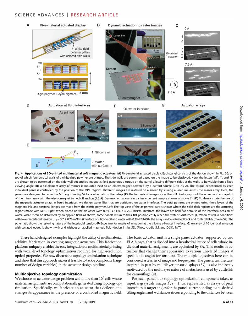
To highlight the potential of multimaterial actuator arrays in passivedisplay applications, we enhance the fundamental actuator design(Fig. 2G) with two extra materials, as shown in Fig. 4A. Vertical slabsare printed on top of each panel with RIGmixed with a white pigment.The sides of the vertical slabs are textured with cyan-colored polymersuch that different images can be displayed by controlling the panel’spitch. The panel array is designed to show the letters “M”, “I”, and “T”when actuated by a magnetic field.
To dynamically actuate our printed displays, we use an electro-magnet powered by a current source to generate a tunable magneticfield.We print an array of six elements on a special substrate to producea mirror-like finish on one side of the print. This substrate is preparedby drop casting and annealing a reactive silver ink on a PI sheet (seeMaterials and Methods). The silver layer peels along with the print as
3 of 14

SC I ENCE ADVANCES | R E S EARCH ART I C L E
on January 6, 2020http://advances.sciencem
ag.org/D
ownloaded from
A C
D E F
B
Tran
smis
sion
fact
or
Tran
smis
sion
fact
or
Mag
netiz
atio
n/M
(em
u/g)
Wavelength (nm)
0.6
0.4
0.2
0
1.0
0.9
0.8
0.7
Stre
ss (M
Pa)
0.2
0.1
0
400 500 600 700Wavelength (nm)
400 500 600 700
Strain (%)0 20 40 60 80
Magnetic field H (103 Oe)–10
–5
0
5
0 10
0.04 mm0.06 mm0.09 mm0.11 mm
0.04 mm0.06 mm0.09 mm0.11 mm
Stre
ss (M
Pa) 10
15
5
0
Strain (%)
2 × 2 array
0 5 10Strain (%)
0 4 8S
tress
(MP
a)
50
25
0
MPC RIG
ELA
G H
Btp
th
whlh
lpMPC
Rigid polymer
Elastictorsional
hinge
5 mm
Fig. 2. Material property library. (A) The transmission through the MPC shown as a function of the wavelength for films of varying thickness, measured using aspectrophotometer. (B) The transmission through the clear rigid material shown as a function of wavelength for multiple film thicknesses. (C) Magnetization versusapplied magnetic field for the MPC measured at room temperature. Magnetic nanoparticles make up ∼12% of the overall weight of the MPC. Typical mechanical stress-strain curves for the ELA, MPC, and the rigid polymer (RIG) are shown in (D) to (F), respectively. Elastic moduli of the polymers at linear strains, averaged from threesamples each, vary significantly—ELA (528 kPa), MPC (507 MPa), and RIG (1290 MPa). (G) The schematic shows the fundamental hinge-based design with panel lengthlp and thickness tp. In this design, the panel is sectioned into two equal portions of RIG and MPC. The panel is attached to rigid boundaries on two sides with ELAtorsional hinges of length lh, width wh, and thickness th. On the application of a magnetic field, the magnetic portion of the panel generates a torque. This is used as thefundamental block in the manually designed samples. (H) Image of a 2 × 2 array of panels each with two axes of rotation. The dark brown regions of the image showthe MPC material, and the translucent portions show the rigid materials. The elastic torsional hinges are nearly identical to the rigid polymer in appearance. On theapplication of a magnetic field, each panel exhibits a unique combination of two-axis angular rotations. The top view of the flat as-printed sample is shown on the left.(Photo credit: S.S. and D.S.K., MIT.)
Sundaram et al., Sci. Adv. 2019;5 : eaaw1160 12 July 2019 4 of 14

SC I ENCE ADVANCES | R E S EARCH ART I C L E
on January 6, 2020http://advances.sciencem
ag.org/D
ownloaded from
the actuator array is removed from the PI film (after printing). Thesilver regions freely exposed on both sides are then etched. A laser line isprojected onto the reflective side of these panels and the angular tilt ofthe panels is dynamically controlled with the electromagnet using thesetup shown in Fig. 4B. The laser line reflected from the mirror array isimaged on a screen; here, the panels are designed to tilt differently toraster theMIT logo shown in red (movie S1). Schematic of the physicalsetup is shown in fig. S7. The two images shown in Fig. 4C are photo-graphs of the laser line on the printed actuator array and the screenwhen the electromagnet is turned off and when powered by a 7.5-Acurrent source (magnetic field settings are described inMaterials andMethods).
A critical advantage of magnetic actuation is in the potential for un-tethered actuation, which is useful in conductive or liquid environmentswhere electrically driven actuators need careful electrical isolation. Fur-thermore,magnetic actuation is also useful for actuation inside the bodywithout requiring any external connections for actuation; i.e., the actu-ated part does not require a physical connection to a power supply (58).
Sundaram et al., Sci. Adv. 2019;5 : eaaw1160 12 July 2019
In Fig. 4 (D to F), we show untethered actuation in conductive fluidinterfaces. The image on the left (Fig. 4D) shows the as-printed sample,containing four individual petals that can be actuated.When the printeddevice is placed on the air-water (with surfactant and colored blue)interface, as shown on the right, the petals can be lifted up from thewater surface by attracting the magnetic regions (design in fig. S8).However, the larger interfacial tension makes repeatable actuationchallenging. Repeated actuation cycles can be performed when theprinted sample is placed at the silicone oil-water interface (interfacialtensions12 =∼ 3.7mN/m), schematically shown in Fig. 4E. Experimen-tal results are shown in Fig. 4F and movie S2. It is noteworthy that theelastic hinge effectively acts as a rotating joint here. The torsional stiff-ness is dominated by the interfacial tension experienced by the petalswhen leaving the silicone oil-water interface.
The number of elements in these actuator arrays is generally easy toscale by tiling identical actuators. To demonstrate this, we tile actuatorpanels with spikes (Fig. 4G; see fig. S9 for design), inspired by the ge-ometry of scales seen on shark skins.
B CA
150
100
50
0
Distance (cm)0 2 4 6
1Dev.Simulation
234
Distance (cm)0 2 4 6
60
40
20
0
Def
lect
ion
(°)
1Dev. 23Simulation
tp
th
whlh
lp1lp2
B
E F
0.01 0.1
0.1
1
1Frequency (Hz)
10Time (s)
Ang
ular
dis
plac
emen
t (°)
0 200
0 50
0 10
1°0.0
56 H
z
0.56 H
z
0.1 H
z
1 Hz
10 H
z
5.6 H
z
3.2 H
z
1.8 H
z
1 Hz
0.032
Hz
0.32 H
z
0.018
Hz
0.18 H
z
0.01 H
z
0.1 H
z
D
0.10.1
1
1Frequency (Hz)
10
***
p
Fig. 3. Actuator characteristics—Forces, displacements, and actuation bandwidth. (A) To characterize the actuator performance, we used the fundamental design(Fig. 2G) with a small change. Here, only a fraction of the panel thickness, tp, is filled with MPC, denoted by l. The following results were obtained with a rectangularpanel of size lp1 × lp2 = 8 mm × 9 mm, thickness tp = 1 mm, l = 0.15, and hinges with dimensions Wh = 0.5 mm, lh = 1 mm, and th = 0.25 mm. (B) Measured blockingforces of four identical devices shown as a function of the distance from the 2″ by 2″ by 0. 5″ magnet along with corresponding simulation results (see magnet,measurement setup, and simulation details in Materials and Methods). (C) Measured angular deflections of three identical devices as a function of distance fromthe magnet. (D) Optically tracked angular displacements as a function of time for actuation at frequencies from 0.01 to 10 Hz. (E) Angular displacement amplitudesas a function of frequency for three devices. (F) The apparent large-amplitude bandwidth depends on the setup of the magnetic field since the force experienced bythe actuator itself varies with the displacement. This is highlighted in this plot with two cases—in one case, the force experienced by the actuator increases mono-tonically with angular displacement (⋆), and in the other case, there is a stable angular displacement when the panel aligns with the direction of maximum gradient(⋆⋆). See fig. S5 for corresponding time curves and details of the setup.
5 of 14
SC I ENCE ADVANCES | R E S EARCH ART I C L E
on January 6, 2020http://advances.sciencem
ag.org/D
ownloaded from
These hand-designed examples highlight the utility of multimaterialadditive fabrication in creating magnetic actuators. This fabricationplatformuniquely enables the easy integration ofmultimaterial printingwith voxel-level topology optimization required for high-resolutionoptical properties.We nowdiscuss the topology optimization techniqueand show that this approachmakes it feasible to tackle complexity (largenumber of design variables) in the actuator design pipeline.
Multiobjective topology optimizationWe choose an actuator design problem with more than 106 cells whosematerial assignments are computationally generated using topology op-timization. Specifically, we fabricate an actuator that deflects andchanges its appearance in the presence of a controlled magnetic field.
Sundaram et al., Sci. Adv. 2019;5 : eaaw1160 12 July 2019
The basic actuator unit is a single panel actuator, supported by twoELA hinges, that is divided into a hexahedral lattice of cells whose in-dividual material assignments are optimized by SA. This results in ac-tuators that change their appearance to various unrelated images atspecific tilt angles (or torques). The multiple objectives here can beconsidered as a series of image and torque pairs. The general architecture,inspired in part by multilayer tensor displays (59), is also indirectlymotivated by the multilayer nature of metachrosis used by cuttlefishfor camouflage (4).
For each panel, our topology optimization component takes, asinput, n grayscale images ~I
i, i = 1…n, represented as arrays of pixel
intensities; n target angles for the panels corresponding to the desiredtilting angles; and n distances di corresponding to the distances between
A B CFive-material actuated display
White rigid-polymer pillars
with colored side walls
Rigid polymer + cyan pigment
On
Off
Dynamic actuation to raster images0 A
7.5 A
5 mm
Scr
een
Act
uato
r
G
Off
On
Actuator arrays
10 mm
D
E
FActuation at fluid interfaces
As printed
WaterAir
Silicone oilWater
Off
On
1: Silicone oil
2: Waterwith surfactant
σ12
BF
Fint
10 mm
Oil-water interface
Laser line
Screen
3D-printedactuator
Electromagnet
7.5 A
I
10 mm
Fig. 4. Applications of 3D-printed multimaterial soft magnetic actuators. (A) Five-material actuated display. Each panel consists of the design shown in Fig. 2G, ontop of which four vertical walls of a white rigid polymer are printed. The side walls are patterned based on the image to be displayed. Here, the letters “M”, “I”, and “T”are chosen to be patterned on the side wall. An applied magnetic field generates a torque on the panel, allowing different sides of the walls to be visible from a fixedviewing angle. (B) A six-element array of mirrors is mounted next to an electromagnet powered by a current source (0 to 7.5 A). The torque experienced by eachindividual panel is controlled by the position of the MPC regions. Different images are rastered on a screen by shining a laser line across the mirror array. Here, thepanels are designed to raster the MIT logo. See fig. S7 for a schematic of the setup. (C) The two sets of images show the still photographs of the screen and a snapshotof the mirror array with the electromagnet turned off and on (7.5 A). Dynamic actuation using a linear current ramp is shown in movie S1. (D) To demonstrate the use ofthe magnetic actuator arrays in liquid interfaces, we design water lilies that are positioned on water interfaces. The petal patterns are printed using three layers of themagnetic ink, and torsional hinges are made from the elastic polymer. Left: The top view of the as-printed part is shown where the solid dark regions are the actuatingregions made with MPC. Right: When placed on the air-water (with 0.2% FC4430, s = 20.9 mN/m) interface, the leaves are held flat because of the interfacial tension ofwater. While it can be deformed by an applied field, as shown, some panels return to their flat position easily when the water is disturbed. (E) When tested in conditionswith lower interfacial tension s12 = 3.7 ± 0.78 mN/m (interface of silicone oil and water with 0.2% FC4430), the array can be actuated back and forth reliably (movie S2). Theschematic shows the restoring nature of the interfacial tension. (F) Experimental results of actuation at the silicone oil-water interface. (G) An array of 16 identical actuatorswith serrated edges is shown with and without an applied magnetic field (design in fig. S9). (Photo credit: S.S. and D.S.K., MIT.)
6 of 14

SC I ENCE ADVANCES | R E S EARCH ART I C L E
http://advanD
ownloaded from
the panel array and the permanent magnet at which the images shouldbe revealed. The material distribution is generated at the individual celllevel as the output, relying on the contrast in the optical and magneticproperties of RIG and MPC. Material assignments for each cell aremade at a cell resolution of 3 × 3 × 1 voxels here, i.e., 101.5 mm by101.2 mm by 6.4 mm.
We represent the material distribution as an indicator function cjthat describes whether a cell at location j in the panel contains MPCor not. The appearance of a given material distribution at a given angleis computed by shooting rays from the center of each pixel and trac-ing the paths of an array of light rays through the different voxels inthe panel (Fig. 5A). Here, we assume a diffuse light source illuminatingthe panels frombelowand assume that reflection and scattering are neg-ligible. The observer is assumed to be looking at the panel from a suf-ficiently large distance above the panel. Letting cRIG and cMPCdenote thelight transmittances of RIG and MPC, the intensity Ik of a pixel kcorresponding to a single ray can be written as
Ik ¼ cdRIGRIG ˙c
dMPC
MPC ð1Þ
where dRIG and dMPC are the total distances traversed by the ray throughRIG and MPC, respectively. We use measured values of cRIG ≈ 1 andcMPC = 0.58 for the transmittances. The transmittance through fivelayers of MPC, i.e., 3% of the total thickness of the panels that we opti-mized in practice, is visually indistinguishable from that of a fullyopaquematerial. Thus, to overcome the limited intensity resolution that
Sundaram et al., Sci. Adv. 2019;5 : eaaw1160 12 July 2019
on January 6, 2020ces.sciencem
ag.org/
can be achieved with MPC, we use halftoning and rely on the ability ofthe human eye to fuse dotted patterns into continuous tones.Wemodelthis by blurring the ray-traced images Ii(c) with a 5 × 5 pixel Gaussianconvolution kernel p before comparing them to the input target images.In practice, as shown in Fig. 5B, the dot gain due to droplet spreading ormisalignment plays a critical role in the overall appearance.We accountfor this by correcting the estimated fraction of the materials in each cellbefore ray-tracing by convolving the binarymaterial assignment cjwitha 3 × 3 kernel (experimental dot gain measurements and modeling de-tails are shown in fig. S10 and discussed in Materials and Methods).
The distribution of theMPC cells inside the panel affects not only itsoptical properties but also its mechanical behavior under the externalmagnetic field. Therefore, the two objectives (appearance and angulardisplacement) are coupled through the locations of theMPCcells.Morespecifically, each MPC cell contributes to the net torque generated, ti,for a given distance di (between the panel and the magnet) dependingon the position of the cell in the panel. Assuming for now that eachlateral ELA hinge connecting the panel to the rigid frame can bemodeled as a torsion spring with torsion stiffness k, the tilting angleassumed by the panel in its equilibrium state can be written as
qi ¼ ti
2kð2Þ
Controlling the torsion bars’ stiffness by changing the geometry ofthe hinges is not sufficient, since we want to control various tiltingangles simultaneously. Therefore, we fix the dimensions of the hingesand precompute target torques~ti to be exerted on the axis of the panel tomake it rotate as desired. We then add hard constraints to the optimi-zation that force the torques ti corresponding to the distribution c tomatch these precomputed torques~ti. In practice, to account for the non-linear behavior of the soft ELAhinges, the tilting angle corresponding toa given torque is computed using a finite elementmethod that simulatesthe deformation of the hinges (the soft-joint finite element solver is de-scribed in Materials and Methods). The target torques ~ti are then ob-tained by using a bisection method. Our original material distributionproblem can then be cast as
minc
EðcÞ ¼ ∑n
i∥p � IiðcÞ � ~I
i∥44
s:t: ti � ~ti ¼ 0;∀i ∈1…n ð3Þwhere * denotes the convolution operator. Our use of the L4 norm ismotivated by the fact that, in practice, it offers a good compromise togenerate panels with both low average error and low maximum error.Low index norms help reduce the number of mismatched pixels butmight lead to panels for which themaximumerror is locally high, whichwe observedwhen using an L2 norm.High index norms help reduce themagnitude of the maximum error but might lead to a larger number ofmismatched pixels. Inspired by stochastic halftoning techniques (26, 60),we solve the problem (3) using an SA procedure (61) augmented with anonsmooth penalty term, which, unlike quadratic penalty functions,allows for strict satisfaction of the constraints (62). For our specific pro-blem, we write this additional term as
cðcÞ ¼ ∑n
imaxð0;∥tiðcÞ � ~ti∥1 � DÞ ð4Þ
A B
Ray-traced image
Ray-traced image (tilted)
Panel cross section
Panel cross section(tilted)
Vertical column of MPC voxels (ideal)
Effect of droplet spreading
Misalignmentbetween layers
Fig. 5. Panel appearance computation. (A) The appearance of the panel asviewed from above is computed by shooting vertical rays through the panel. By com-puting the total distances traversed by each ray through each material, the ray-tracedimages can be obtained. Here, three layers each filled with RIG and MPC are shown.Multiple images can be volumetrically encoded in space based on the desired viewingangles. This can be seen in different ray-traced images obtained from a single structurewith varying tilting angles. While not explicitly shown here, the volumetric positions ofthe MPC cells also define the torque in response to a magnetic field. Note that onlythree layers are shown in the schematic for simplicity; in practice, more than 100 layersare typically used. (B) A vertical column of MPC voxels (top) is widened in practice dueto droplet spreading (middle) or slight misalignment in the positions of the drops inconsecutive layers (bottom).
7 of 14

SC I ENCE ADVANCES | R E S EARCH ART I C L E
http://advances.scienceD
ownloaded from
and use D = 10−7 MPa to account for small rounding errors when eval-uating the torques. The augmented objective L is then expressed as
Lðc;TÞ ¼ EðcÞ þ 1TcðcÞ ð5Þ
where T is the SA temperature. We initialize c with a zero-valueddistribution. At each iteration of the algorithm, a candidate distributionis generated by changing the material assignment of two cells that arerandomly selected.We accept the new distribution if it either lowers theobjective value or raises it with a probability equal to e(L(ct−1,T) − L(ct,T))/T,where L(ct − 1, T) and L(ct , T) are the previous and current objectivevalues and T is the current simulation temperature. This prevents thealgorithm from getting trapped in local minima while simultaneouslyimproving the exploration of the entire design space. For our final ex-ample, we use 108 steps and a linear cooling schedule. Contrary togradient-basedmethods commonly used in topology optimization (15),our SA procedure does not require a linear system to be solved at everystep and can effectively cope with the high number of variables of ourproblem (one for each of the 106 cells). The large number of steps re-quired to approximate a global optimum, typical of SA algorithms, islargely counterbalanced by the fast evaluation of the function (5), which,in practice, can be effectively computed by noting that a change in avoxel material only affects a few pixels in the ray-traced images.
We applied thismethodology for the design and optimization of twodifferent structures, the results of which can be directly fabricated usingour printer. The first example consists of a single rotating panel thatreveals two different images: one in the rest state and the other at a tilt-ing angle of 30° when placed 1.5 cm from the permanent magnet. Theimages correspond to grayscale 186 × 186 pixel versions of the twopaintings Self-Portrait with Grey Felt Hat by Van Gogh (Public domain
Sundaram et al., Sci. Adv. 2019;5 : eaaw1160 12 July 2019
image, cropped and gray scaled) andThe Scream byMunch (63), whosepixel intensities were linearly rescaled tomap the range from 0.2 to 0.8.Assignments for thematerials are considered at a resolution of 101.5mmby 101.2 mmby 6.4 mm for the panel with external dimensions 18.89mmby18.83mmby1.025mm(or 186by186by 160 cells). As shown inFig. 6and movie S4, the panel rotates as predicted under the applied externalmagnetic field and displays images that are in good agreement withsimulation. The results are shown past the 30° tilt angle; the panelappears narrower inwidth on tilting. Because of the limit set by the tiltingangle, ghosting in areas corresponding to very different intensities in thetwo target images is visible in the results of the optimization and repli-cated in the prints. This effect is expected and can be reduced bydecreasing the dynamic range of the input images a priori.
To evaluate and quantify the performance of the topology-optimizedactuator, we experimentally measured and simulated the blockingforce and the angular deflection as a function of the distance betweenthe actuator and the magnet. We used an offset while positioning themagnet and standardized this in both the experimental setup andsimulations—this is to ensure that the actuator tilts in the same direc-tion consistently, given the similarity in the magnetic material contentin each half of the actuator. The measurement setup is shown in fig.S12. The blocking force was measured using a calibration cantilever asbefore (Fig. 3B) as a function of the normal distance separating themagnet and the actuator and shown in Fig. 7A. The simulation of theidentical physical setupwas performed in 3Dwith no fitting parametersand shows a good match with the experimentally obtained forces. Themeasured angular deflection is shown in Fig. 7B. The variation in themeasured and simulated angular deflections is likely due to a mismatchin the printed hinge geometry with respect to the ideal design. A scaledversion of the basic design (matching the dimensions of the topology-optimized actuator) was used to perform long-term tests up to 1000
on January 6, 2020m
ag.org/
Increasing tilt
Input images
Printed actuator
Ray-traced images
0° 18.2° 34.1° 43.9°5 mm
A
C
B
Fig. 6. Panel optimization for both optical and mechanical properties. Given a pair of target grayscale images. Left: ‘Self portrait with Grey Felt Hat’, van Gogh.Image from public domain. Right: from (63). Image used with permission. (A) Corresponding to desired top views of the panel array at two different tilting angles (here,0° and 30°), our topology optimization framework optimizes the distribution of the RIG and MPC in the panels such that they tilt to the desired angles and theirappearances match the target images. (B) Optimized panel appearances as computed by our ray-tracer. (C) Photographs of the 3D-printed topology-optimized sampleshowing the gradual transition from the “Van Gogh” portrait to the “Scream” image with increasing tilt angle (additional results in fig. S11 and movie S4).
8 of 14

SC I ENCE ADVANCES | R E S EARCH ART I C L E
on January 6, 2020http://advances.sciencem
ag.org/D
ownloaded from
cycles (0.56 Hz) showing no degradation in performance (Fig. 7Cand movie S3).
The demonstrated scheme can be easily extended to larger arraysand different images. We demonstrate this with a second examplefeaturing a 3 × 3 panel array with external dimensions 30 mm by30 mm by 1.025 mm, which is optimized to replicate two textures(grass and stones) at 0° and 30°, respectively (see fig. S11). Whenthe panels are made small, the fraction of MPC required to rotatethe panels to the desired angles is substantial. This translates into aglobally darker area on one-half of each panel.
DISCUSSIONOverall, the actuators shaped by topology optimization demonstrate theability of our scheme in optimizing complex actuators and its enablingpotential in the use of magnetic actuators for camouflage applications.The examples we show here demonstrate two image transitions as thesehave the best visual clarity for small actuator thickness (correspondswith printing time). To preserve the visual claritywhile encoding greaternumbers of images (>2), a larger actuator thickness is required. This isstraightforward in our optimization procedure as it is currently writtenfor a flexible number of images. However, this increases the printing
Sundaram et al., Sci. Adv. 2019;5 : eaaw1160 12 July 2019
time in our fabrication process. Furthermore, to improve the opticalquality of our printed actuators, we explicitly tailored our droplets tobe significantly smaller than the typical droplet size (droplet volumeof ∼8 pl as compared to the typical ∼22.5 pl). While this flexibility incontrolling the process enables the sharp contrast in our images, itcomes with the cost of increased printing time. In the future, this speedand size limitation can be overcome by increasing the number of print-heads to improve the throughput. Commercial drop-on-demand 3Dprinters tackle large scale by using several printheads and offer easyaccess to this technology; however, they are closed systems that donot allow editing the process or the inks.
The topology optimizer that we developed is aimed at satisfying twodifferent objectives, i.e., matching target optical properties andmatching target titling angles.However, in our case, these two objectivesare not equally difficult to reach—there are manymaterial distributionsthat will meet the tilting angle criteria; however, it is far morechallenging to match the target images exactly. We therefore decidedto treat the first goal (target angle) as a hard constraint and handledthe second (target appearance) in the least square sense. However, itis possible to give a more symmetric role to both objectives and thereforegeneralize themethod to problems forwhich no objective can be exactlymet. Thiswould not present any new challenges sincewe already handle
Def
lect
ion
(°)
Time (s)
Time (s)Normal distance, d (cm)
40
20
0
200
100
0
Def
lect
ion
(°)
Def
lect
ion
(°)
40
30
20
10
0
75
50
25
0
0
0 500 1000 1500
5 10 15
0 2 4 6
Normal distance, d (cm)0 2 4 6 895 900 905 1785 1790 1795
A
B
C
Fig. 7. Characteristics of the topology-optimized actuator and long-term tests. (A) The blocking force produced by the Van Gogh actuator (Fig. 6) was measuredand simulated as a function of distance to the magnet. To ensure that the actuator was consistently actuated on the same side each time, the actuating magnet wasoffset toward one-half in all simulations and experimental characterization. The measurement setup is shown in fig. S12. In addition, note that all simulations areperformed without any fitting parameters. (B) Measured and simulated angular displacement of the topology-optimized Van Gogh actuator as a function of the normaldistance between the actuator and the magnet (setup in fig. S12). (C) To test the long-term performance of the large actuator and the reliability of the hinges, we cycleda scaled version of the basic design (Fig. 3A) with dimensions identical to the Van Gogh actuator for 1000 cycles (see movie S3).
9 of 14

SC I ENCE ADVANCES | R E S EARCH ART I C L E
on January 6, 2020http://advances.sciencem
ag.org/D
ownloaded from
the problem by minimizing a weighted sum. In this sense, the tech-nique that we present could be easily extended to other multiphysicsproblems, including problems with more than two objectives. Thisholds as long as fast evaluation of the involved quantities is possible,which demands an efficient problem-specific simulation tool. Anotherinteresting aspect to study when considering multiphysics problemswith coupled (and usually conflicting) objectives is related to the Paretofront, i.e., the entire set of optimal trade-offs. How to effectivelycompute and explore this set in the general case is a fascinating andopen research question.
Drop-on-demand inkjet-based 3D printing is well suited in the fab-rication of topology-optimized designs and in generating high-resolutionoptical properties due to its ability to print with a large number ofnozzles at high resolution and with multiple inks at once. However,the printing process demands inks within very tight rheological proper-ties and particle sizes—this makes it challenging to develop diversefunctional inks (57). Increasing the actuating force (and, in parallel, re-ducing the power requirements) can be easily achieved by improvingthe loading of the magnetic nanoparticles in the ink. We observed thatourMPC inkwas unstable when the loading of Fe3O4 nanoparticles wasincreased above 12 wt %. The use of anisotropically shaped magneticnanoparticles resulted in frequent clogging of the nozzles. Despite theremaining challenges in developing new inks andmaterials, a wide rangeof materials can be currently fabricated using this process: UV-curablerigid and stretchable acrylate polymers, liquid electrolytes, and conductiveand semiconducting films (36). Using similar printing processes, othergroups have demonstrated a wide range of different actuators includingelectrically actuated dielectric elastomer actuators (55, 56).
The MPC ink we use here allows tuning the optical properties andthe force generated by a voxel simultaneously. In that sense, magneticmaterials and actuation are particularly useful here alongwith their abilityto be controlled without physical tethers. However, it is still challengingto actuate a large array of actuators in close proximity that are each in-dividually controllable. Generating magnetic fields with well-controlledspatially varying intensities is a long-standing challenge. This is not aproblemwe address here but it is useful to note that this is an importantrequirement for individually addressable arrays in the future. Recentprogress on achieving selective control ofmagnetic elements have reliedon spatial field control (64, 65), as well as selective actuation usingaligned nanoparticles (66).
Fully designing the entire pipeline—starting inks, device architec-tures, optimization-based design synthesis, and printing hardware—enhances our freedom in controlling each of these individual elements.It also allows us to account for the physical system in our optimization;i.e., our optimization is fabrication aware. For instance, we take intoaccount the effects of droplet spreading while evaluating the opticalappearance properties. Likewise, the loading of the Fe3O4 nanoparticlesin the MPC ink results in increased opacity of the ink, but the use ofhalftoning allows us to expand on the range of perceived pixel intensi-ties. However, it is useful to note that fabrication-aware optimization isclosely tied to the specific set of materials and fabrication processesused—any changes to the materials or fabrication process would re-quire reevaluation of these physical effects. Furthermore, the abilityto control each of these parameters increases the overall complexityof our pipeline.
The topology-optimized actuator presented here is an example of acoupledmultifunctional systemwithmore than 106 design dimensions.The accompanying fabrication toolkit can be used to design actuatorsalong with sensors and basic computing elements such as transistors
Sundaram et al., Sci. Adv. 2019;5 : eaaw1160 12 July 2019
and amplifiers (42). To enable the vision of robotic/autonomous com-posites that unify materials and machines (1, 2, 42), an integration of amultitude of functions is required. There remain challenges in develop-ing different elements (sensors, processors, and actuators), as well asbroader challenges in their subsequent large-scale integration andenabling overall self-sufficiency (by integrating power sources andcommunication elements). These developments are expected to beaccompanied by increases not only in the complexity of materials,design demands, and fabrication processes but also in the complexityof the overall system architecture. Most of these foundational strategiesare yet to be developed. We expect that the automated design and fab-rication of optimized, multifunctional actuators with minimal humanintervention is a step toward tackling this broader challenge.
CONCLUSIONWe demonstrate an approach that unifies multimaterial 3D printingwith topology optimization and brings us one step closer to automatedfabrication from purely functional goals. The topology optimizationprocedure generates complex high-dimensional designs while optimiz-ing multiple objectives, while our printing process enables the directfabrication of these topology-optimized,multimaterial designs.We spe-cifically demonstrate this by optimizing and fabricating a multimaterialactuator that displays two independent images at specific deflectionangles, controlled by an applied magnetic field. Voxel-level flexibilityin material choices from both the fabrication and shape optimizationperspective enables the first steps toward fully automated design andfabrication of complex, multimaterial devices.
MATERIALS AND METHODS3D printing process summaryWeused a custom-built inkjet-based 3Dprinter that takes a voxel-basedstructure as input for printing as previously reported (42, 54). All theinks used in this work were made from acrylate-based monomersand oligomers that can be cross-linked by UV light–initiated free-radical polymerization. The UV-LED array in our printer used in thiswork has an intensity of∼2.1W/cm2 at 365 nm. The thin elastic (ELA)hinges used in our actuator designs are fragile. To facilitate easy re-moval, our samples were printed on a 125-mm sheet of PI (McMaster-Carr, Elmhurst, IL, USA) and coated with a thin layer of poly(acrylicacid) (PAA ∼50 kg/mol, ∼25% solution in water, Polysciences Inc.,USA) prepared by drop casting. On completion of the print (typicalprint time ∼2 to 3 hours), the samples on the PAA-coated PI sub-strates were left in water overnight, by which time the printed partwas detached from the substrate. For our samples with a silver mirrorfinish (Fig. 4, B and C), the silver layer was prepared by drop casting areactive silver ink on a PI substrate and then sintered at 80°C for 2 minon a hotplate. Structures printed on top of the silver ink can be easilydetached from the PI substrate since the precipitated silver nanoparti-cles adhere strongly to our UV-cured polymers and weakly with the PIsubstrate. We used a 1:1 (vol) mixture of H2O2:NH4OH as the silveretchant to remove freely exposed silver.
ELA and RIG inksThe rigid polymer (RIG) ink was formulated by mixing the followingcomponents: 59 wt % of Genomer 1117 [Rahn USA Corp., (5-ethyl-1,3-dioxan-5-yl) methyl acrylate], 32 wt % of Genomer 2252/G (RahnUSACorp., vinyl ester resin/epoxy acrylate), and 9wt% ofM300 (Rahn
10 of 14

SC I ENCE ADVANCES | R E S EARCH ART I C L E
on January 6, 2020http://advances.sciencem
ag.org/D
ownloaded from
USA Corp., trimethylolpropane triacrylate). The components weremixed together and stirred at 600 rpm at room temperature for1 hour. Irgacure 819 (2 wt %) [BASF Chemical Company, bis(2,4,6-trimethylbenzoyl)-phenylphosphineoxide]was added as the photoini-tiator for free-radical polymerization underUV light. 4-Methoxyphenol(0.1 wt %) (Sigma-Aldrich Corp.) was added to inhibit free-radical po-lymerization for any trace amounts of free radicals induced by ambientlight or impurities and to improve the resolution.
The elastic (ELA) ink was formulated bymixing 48 wt% of CN3105(Sartomer USA LLC., low-viscosity oligomer), 33 wt % of SR504[Sartomer USA LLC., ethoxylated (4) nonylphenol acrylate], 5 wt %of Genomer 4215 (Rahn USA Corp., aliphatic polyester urethane acry-late), and 10 wt % SR313B (Sartomer USA LLC., C12 and C14 alkylmethacrylate). The mixture was heated at 60°C for 1 hour and thenstirred at 600 rpm for 1 hour. Irgacure 819 (1 wt %) and 0.5 wt % ofITX (Rahn USA Corp., isopropylthioxanthone) were added as photo-initiators. 4-Methoxyphenol (0.1wt%)was added to inhibit free-radicalpolymerization. All inks were stored in UV-protected containers to in-hibit curing from ambient light.
Colored inks were prepared with pigment dispersions (RJA dis-persions LLC) added to the rigid ink formulation. The magenta andcyan pigmented inks were prepared by adding 1 g of the dispersion to100 g of the rigid ink formulation. The white pigmented ink wasprepared by adding 5 g of the pigment dispersion to 100 g of the rigidink formulation. All inks were then stirred at 600 rpm for 1 hour andthen filtered with a 1-mm filter before use.
Ink viscosities were measured using a viscometer (DV-I Prime,Brookfield Engineering) and optimized to be∼11 to 15 cP at 70°C. Sur-face tension of the inks was measured using a tensiometer (DCAT11,DataPhysics) and optimized to be ∼30 to 35 mN/m under printconditions.
MPC composite inkThemagnetic nanoparticle-based ink was formulated as follows: 12 wt %of iron(III) oxide nanoparticles (US Research Nanomaterials Inc.),80 wt % of the rigid ink formulation (without photoinitiators andphotoinhibitors), and 8 wt % of Genomer 1116 were mixed together.DISPERBYK110 (5 wt %) (BYK Additives & Instruments, nonionicdispersant) was added on top of the total weight of the iron(III) oxidemixture (5 g of dispersant added for every 100 g of magnetic ink). Themagnetic ink was then run on a bead mill (M100 VSE TEFC, Engi-neered Mills Inc., USA) with 300-mm yttria-stabilized zirconia beadsfor 7 hours at 4000 rpm to break down agglomeration and stabilizethe nanoparticles within the suspension. After milling was completed,the inkwas transferred to a clean 250-ml container. Irgacure 819 (2wt%)and ITX were added to the suspension and mixed vigorously with aspatula for several minutes. 4-Methoxyphenol (0.1 wt %) was addedlastly as a photopolymerization inhibitor. The ink was allowed to sitfor 6 hours to completely dissolve the photoinitiators in the ink. Theink was then filtered with a 1 -mm filter before use.
Polymer characterization measurementsThermogravimetric analysis (TGA) measurements were performedusing a Discovery TGA (TA Instruments, USA). A 3D-printed slab ofmagnetic material (1 mm by 1 mm by 0.5 mm) was placed on top of aplatinum pan, and the sample temperature was ramped from 50° to800°C in air at a 10°C/min ramp rate. The retained weight percent ofthe MPC was measured to 11.93%, verifying the nanoparticle loading(fig. S1A). A larger weight percent was measured when TGA was per-
Sundaram et al., Sci. Adv. 2019;5 : eaaw1160 12 July 2019
formed in nitrogen-rich atmosphere, potentially resulting from excesspolymer retention after the tests.
Vibrating sample magnetometry measurementsVibrating sample magnetometry (VSM) measurements were performedusing an 800-VSMmodel (MicroSense, USA). Eight-millimeter disks ofthe MPC material were 3D-printed with varying thicknesses (0.1 to1mm), mounted on glass tips, and characterized. Typically, the appliedmagnetic field was cycled between −104 and 104 Oe. Themagnetizationof the MPC samples saturated to ∼5.7 emu/g.
Mechanical characterizationThe stress-strain curve for each material was measured on a tabletopmechanical tester Instron 5944 (Instron, Norwood, MA, USA) with a2-kN maximum load. The samples were 3D-printed and mechanicallytested. The rigid polymer andMPCmaterial weremeasured at 0.5mm/min strain rate, and the elastic polymer was measured at 1.5 mm/min.The measured moduli for RIG, ELA, and MPC are 1290 MPa, 528 kPa,and507MPa, respectively. Poisson’s ratiomeasurementswere performedon 3D-printed samples of the elastic material using designs with fourcircular features along the x and y axis of the sample. These axis-alignedpoint pairs are positioned at equal distances. Samples were clamped onthe Instron mechanical tester, and a set of images were taken at variouscontrolled strains. The distance along the x and y axis along the fourcircular points was measured at varying strains with the optical micro-scope imaging software (Stream Start software, Olympus Corp., Tokyo,Japan). Figure S1B shows these measurements. Poisson’s ratio wasmeasured to be ∼0.4.
Spectrophotometer measurementsTransmission spectra were measured in the optical wavelengthusing a color i5 benchtop spectrophotometer (X-Rite, USA). Square slabsof varying thicknesses (ranging from 40 to 110 mm) were 3D-printed,and the transmittances of the samples were measured.
Actuator characterization: Force, deflection, andbandwidth measurementsThe actuator characteristics in Fig. 3 were recorded by optical trackingof deflections. For the measurements of forces, a cantilever cut from a0.002″-thick PI sheet was used. The rectangular cantilever was laser-cut with the following dimensions: 0.6″ in length and 0.125″ in width.The stiffness of the cantilever at the tip was established to be 105.9 ±12.0 mN/m by applying different loads. To measure the blockingforce, the calibrated cantilever tip was placed at the actuator edgewith the largest displacement, and the displacement was measuredusing optical images. The force was calculated from the displacementand the stiffness of the calibrated cantilever. The angular deflectionswere directly measured from the optical images. The actuator forceand deflection measurement were performed using the 2″ by 2″ by0.5″ magnet to generate the magnetic field. To measure the angulardisplacement with time for the bandwidth measurements, the edges ofcantilever were tracked from the side (for the small-amplitude displace-ments) and from the top (for the large-amplitude bandwidth) foreach frame. Here, the electromagnet was used for actuation, poweredby 1.5 A at 50% duty cycle (for small amplitude) and 7.5 A at 50% dutycycle (for large-amplitude bandwidth measurements). For the 7.5-Acurrent pulses, a solid-state relay (SSR-25 DD) was controlled by asource meter. All these images and videos were acquired using theCanon macro lens (EF 180 mm f/3.5L Macro USM).
11 of 14
SC I ENCE ADVANCES | R E S EARCH ART I C L E
on January 6, 2020http://advances.sciencem
ag.org/D
ownloaded from
Dot gain—Measurements and simulation detailsDot gain measurements were performed by 3D printing two striped-pattern prints (2- and 4-voxel-wide stripes) of the MPC and the rigidpolymer ink. Dot gain was computed by measuring the actual widthwith respect to the expected design width. Samples were imaged usingan opticalmicroscope, SZ61 (OlympusCorp., Tokyo, Japan), fittedwiththe SC30 digital camera (Olympus Corp., Tokyo, Japan). The widths ofthe stripes of both prints weremeasured using the Stream Start software(OlympusCorp., Japan). Thewidths of theMPC traces and the rigid inkof the 2-voxel-wide stripes were ∼90 and ∼50 mm, respectively. Thecorresponding widths for the 4-voxel-wide stripes were ∼180 and∼100 mm, respectively (fig. S10). The dot gain of the droplets is typicallysymmetric in the in-plane directions.
Thus, in practice, a column of voxels containing MPC appears, onaverage, 30 mm wider than the width of the original droplets depositedby the printer. Dot gain is typically due to drop spreading and slightmisalignment in the positions of the drops of consecutive layers. To ac-count for these effects, we corrected the estimated fraction, or presenceprobability, of magnetic ink in each voxel before ray-tracing the light.This was performed layer by layer by convolving the original binarymaterial distribution with a 3 × 3 kernel q of the form
q ¼ u∥u∥
vT
∥v∥; uT ¼ ½sxrxsx�; vT ¼ ½syrysy� ð6Þ
where si = 15 mm, for i = x, y, is the measured lateral spread of the dropsin the in-plane directions and rx and ry are the voxel resolution along xand y, respectively. The filtered material ratios were used to scale theindividual distance contributions of voxels in the calculation of the totaldistances dRIG and dMPC traversed by the rays.
Soft-joint simulationEach joint connecting the panels to the frame was modeled as a hexa-hedral lattice with 163 elements and simulated with a finite elementmethod using linear basis functions and eight quadrature points perelement. For the ELA material, we used a neo-Hookean materialmodel with energy density W ¼ m
2 ðI1 � 3� 2lnðJÞÞ þ l2 ðlnðJÞÞ2 ,
where I1 and J are the first invariant of the right Cauchy-Green defor-mation tensor and the determinant of the deformation gradient, re-spectively, and l and m are the Lamé parameters. To account forany fabrication-related effects, we further estimated the effective elas-tic modulus of the ELA hinge (357.7 kPa) independently from fabri-cated calibration actuators in fig. S2. The measured Young’s modulus(E) and Poisson’s ratio (n) can be converted to Lamé parameters l andm using l = En/((1 + n)(1 − 2n)) and m = E/(2(1 + n)). The panels andthe frame were treated as rigid bodies. The forces acting on the panelswere computed on a voxelized representation of the panel geometry.We considered both gravitational forces acting on all the voxels of thepanels and magnetic forces due to the external magnetic field actingon the MPC cells. Each of these voxels was modeled as a magneticdipole withmomentmi located at the center ci of the voxel and alignedwith the externalmagnetic field. The forceFi acting on themagnetizedvoxel is thus described byFi=∇ (mi.B).Wemodeled themagnetizationof the MPC cell using the hyperbolic tangent function as MðHÞ ¼±5:67 tanh ð2:8� 10�2
ffiffiffiffiffiffiffiffiffiffi∥H∥
p2Þ, withH expressed in [Oe], which is in
good agreement with the measured data (fig. S13D). The magnitudemi
of the momentmi is then approximated bymi(ci) =M(H(ci))rMPCdV,where rMPC = ∼ 1.2 g/cm3 denotes the density of the cured MPC
Sundaram et al., Sci. Adv. 2019;5 : eaaw1160 12 July 2019
material and dV corresponds to the volume of an individual voxel. Notethat the moment generated by anMPC cell is not constant but dependson the current location of the voxel center, which is affected by the ro-tation of the panel.
Magnetic field—Experimental setup, field computation,and measurementsFor our variable magnetic field experiments, we constructed anelectromagnet using a consumer-grade microwave oven transformer.The transformer was cut to enforce a flux path outside the core, andthe secondary coil was removed. The primary coil (∼114 turns) was re-tained in the core to generate the magnetic field. In laser rasteringexperiments (Fig. 4B), the primary coil was connected to a currentsource (up to 7.5 A). This allowed the field to be dynamically controlledup to ∼45 mT at the sample location. The steepest gradient in themagnetic field is normal to the plane of the six-mirror array, causingthe mirrors to tilt out of plane.
For our remaining experiments, we used a 2″ by 2″ by 0.5″ bar-shaped neodymiumgradeN52magnetmagnetized along its vertical ax-is (y) to generate the external magnetic field. In all our static deflectionmeasurements, we placed the samples ∼1 cm from the surface of themagnet, along the magnetic axis. In this case, the magnetic field canbe derived analytically from the Maxwell equations (67) and is afunction of the dimensions a, b, and c of the magnet (fig. S13A) andits magnetization M = Mez that we assume to be constant. Letting theorigin of the coordinate system be located at the center of the magnet,the field H = (Hx, Hy, Hz) can be written as
Hxðx; y; zÞ ¼ M4p
∑2
k;l;m¼1ð�1Þkþlþmlnðy þ ð�1Þlb
þ rklmðx; y; zÞÞ ð7Þ
Hyðx; y; zÞ ¼ M4p
∑2
k;l;m ¼1ð�1Þkþlþmlnðx þ ð�1Þka
þ rklmðx; y; zÞÞ ð8Þ
Hzðx; y; zÞ ¼M4p
∑2
k;l;m¼1ð�1Þkþlþmatan
ðx þ ð�1ÞkaÞðy þ ð�1ÞlbÞðz þ ð�1ÞmcÞrklmðx; y; zÞ
!ð9Þ
rklmðx; y; zÞ ¼ffiffiffiffiffiffiffiffiffiffiffiffiffiffiffiffiffiffiffiffiffiffiffiffiffiffiffiffiffiffiffiffiffiffiffiffiffiffiffiffiffiffiffiffiffiffiffiffiffiffiffiffiffiffiffiffiffiffiffiffiffiffiffiffiffiffiffiffiffiffiffiffiffiffiffiffiffiffiffiffiffiffiffiffiffiffiffiffiffiffiffiffiffiffiðx þ ð�1ÞkaÞ2 þ ðy þ ð�1ÞlbÞ2 þ ðz þ ð�1ÞmcÞ2
qð10Þ
WeusedM= 950 kA/m as the value for themagnetization, obtainedby fitting the analytical magnetic flux density B = m0H to sample values(see fig. S13, B and C).
All ourmagnetic fieldmeasurements were performed using an F.W.Bell 9500 gauss meter with a probe (∼4.5 mm by 4.5 mm). Measure-ments were typically made in the 3-kG range, which has a reported ac-curacy of ±30 G (or the 300-mT range, ±3 mT).
Silicone oil-water interface experimentsInterfacial tensionmeasurements were performedwith theDataPhysicstensiometer (DataPhysics, Germany) using the PT11 Wilhelmy plate
12 of 14

SC I ENCE ADVANCES | R E S EARCH ART I C L E
(10 mm by 19.9 mm by 0.2 mm) for the air-fluid interface and with theRG11DuNoüy Ring (18.7mm in diameter, 0.37mmwire thickness) forthe silicone oil-water interface.
Imaging and processingAll images and videos were acquired using a digital single-lens reflexcamera (Canon EOS 60D or Canon EOS-1D X, Canon, USA). Whitebalance and exposure were adjusted for visual clarity. Canonmacro lens(EF 180 mm f/3.5L Macro USM), Canon Zoom EFS 18-55 mm f/3.5-5.6, and Canon Zoom EF 28-80 mm f/3.5-5.6 were the lenses used.
http://advances.sciencema
Dow
nloaded from
SUPPLEMENTARY MATERIALSSupplementary material for this article is available at http://advances.sciencemag.org/cgi/content/full/5/7/eaaw1160/DC1Fig. S1. Material characteristics.Fig. S2. Experimental verification of tilting angles.Fig. S3. Two-axis tilting panels.Fig. S4. Dynamic mechanical analysis of the elastic material family used in the softtorsional hinges.Fig. S5. Large-amplitude bandwidth measurements.Fig. S6. Actuator long-term cycling.Fig. S7. Experimental setup for dynamic actuation.Fig. S8. 3D-printed water lily design.Fig. S9. Spike actuator arrays design.Fig. S10. Dot gain images.Fig. S11. Topology optimization—Optical and mechanical properties.Fig. S12. Measurement setup for characterizing the Van Gogh actuator.Fig. S13. Modeling of the external magnetic field.Movie S1. Video showing the dynamic actuation of the reflective panel array used to raster theMIT logo.Movie S2. The printed water lily is placed at fluid interfaces and actuated using a permanentmagnet.Movie S3. Actuation of panel actuators at different frequencies for bandwidth measurementsand long-term actuation (1000 cycles).Movie S4. Topology optimization of actuators.
on January 6, 2020g.org/
REFERENCES AND NOTES1. M. A. McEvoy, N. Correll, Materials that couple sensing, actuation, computation, and
communication. Science 347, 1261689 (2015).2. Y. Mengüç, N. Correll, R. Kramer, J. Paik, Will robots be bodies with brains or brains with
bodies? Sci. Robot. 2, eaar4527 (2017).3. R. Hanlon, C.-C. Chiao, Cephalopod dynamic camouflage: Bridging the continuum
between background matching and disruptive coloration. Philos. Trans. R. Soc. Lond. BBiol. Sci. 364, 429–437 (2009).
4. L. F. Deravi, A. P. Magyar, S. P. Sheehy, G. R. R. Bell, L. M. Mäthger, S. L. Senft, T. J. Wardill,W. S. Lane, A. M. Kuzirian, R. T. Hanlon, E. L. Hu, K. K. Parker, The structure–functionrelationships of a natural nanoscale photonic device in cuttlefish chromatophores.J. R. Soc. Interface 11, 20130942 (2014).
5. D. Panetta, K. Buresch, R. T. Hanlon, Dynamic masquerade with morphingthree-dimensional skin in cuttlefish. Biol. Lett. 13, 20170070 (2017).
6. L. J. Hornbeck, 128 × 128 deformable mirror device. IEEE Trans. Electron Devices 30,539–545 (1983).
7. C. Gong, T. Hogan, CMOS compatible fabrication processes for the digital micromirrordevice. IEEE J. Electron Devices Soc. 2, 27–32 (2014).
8. P. Vettiger, G. Cross, M. Despont, U. Drechsler, U. Durig, B. Gotsmann, W. Haberle,M. A. Lantz, H. E. Rothuizen, R. Stutz, G. K. Binnig, The “millipede”-nanotechnologyentering data storage. IEEE Trans. Nanotechnol. 1, 39–55 (2002).
9. L. Wen, J. C. Weaver, P. J. M. Thornycroft, G. V. Lauder, Hydrodynamic function of biomimeticshark skin: Effect of denticle pattern and spacing. Bioinspir. Biomim. 10, 066010 (2015).
10. A. W. Lang, M. T. Bradshaw, J. A. Smith, J. N. Wheelus, P. J. Motta, M. L. Habegger,R. E. Hueter, Movable shark scales act as a passive dynamic micro-roughness to controlflow separation. Bioinspir. Biomim. 9, 036017 (2014).
11. S. L. Tamm, Mechanical synchronization of ciliary beating within comb plates ofctenophores. J. Exp. Biol. 113, 401–408 (1984).
12. B. Anderson, J. Shultz, B. Jayne, Axial kinematics and muscle activity during terrestriallocomotion of the centipede scolopendra heros. J. Exp. Biol. 198, 1185–1195 (1995).
Sundaram et al., Sci. Adv. 2019;5 : eaaw1160 12 July 2019
13. H. Cruse, What mechanisms coordinate leg movement in walking arthropods? TrendsNeurosci. 13, 15–21 (1990).
14. H. Cruse, V. D¨urr, J. Schmitz, Insect walking is based on a decentralized architecturerevealing a simple and robust controller. Philos. Trans. A Math. Phys. Eng. Sci. 365,221–250 (2007).
15. M. P. Bendsøe, O. Sigmund, Topology Optimization: Theory, Methods and Applications(Springer-Verlag Berlin Heidelberg, 2003).
16. M. P. Bendsøe, N. Kikuchi, Generating optimal topologies in structural design using ahomogenization method. Comput. Methods Appl. Mech. Eng. 71, 197–224 (1988).
17. J. S. Jensen, O. Sigmund, Systematic design of photonic crystal structures using topologyoptimization: Low-loss waveguide bends. Appl. Phys. Lett. 84, 2022–2024 (2004).
18. O. Sigmund, On the design of compliant mechanisms using topology optimization.Mechanics of Structures and Machines 25, 493–524 (1997).
19. H. Zhang, M. Y. Wang, F. Chen, Y. Wang, A. S. Kumar, J. Y. H. Fuh, Design anddevelopment of a soft gripper with topology optimization, in 2017 IEEE/RSJ InternationalConference on Intelligent Robots and Systems (IROS) (2017), Vancouver, BC, Canada, 24 to28 September 2017, pp. 6239–6244.
20. K. Maute, A. Tkachuk, J. Wu, H. J. Qi, Z. Ding, M. L. Dunn, Level set topology optimizationof printed active composites. J. Mech. Des. 137, 111402 (2015).
21. C. Schumacher, B. Bickel, J. Rys, S. Marschner, C. Daraio, M. H. Gross, Microstructures tocontrol elasticity in 3D printing. ACM Trans. Graph. 34, 136:1–136:13 (2015).
22. J. D. Hiller, H. Lipson, Automatic design and manufacture of soft robots. IEEE Trans. Robot.28, 457–466 (2012).
23. N. Cheney, R. MacCurdy, J. Clune, H. Lipson, Unshackling evolution: Evolving soft robotswith multiple materials and a powerful generative encoding. ACM SIGEVOlution 7, 11–23(2014).
24. K. Shea, J. Cagan, S. J. Fenves, A shape annealing approach to optimal truss design withdynamic grouping of members. ASME J. Mech. Des. 119, 388–394 (1997).
25. K. Shea, J. Cagan, Innovative dome design: Applying geodesic patterns with shapeannealing. Artif. Intell. Eng. Des. Anal. Manuf. 11, 379–394 (1997).
26. A. Bermano, I. Baran, M. Alexa, W. Matusk, ShadowPix: Multiple images from selfshadowing. Comput. Graph. Forum 31, 593–602 (2012).
27. S. A. Morin, R. F. Shepherd, S. W. Kwok, A. A. Stokes, A. Nemiroski, G. M. Whitesides,Camouflage and display for soft machines. Science 337, 828–832 (2012).
28. C. Larson, B. Peele, S. Li, S. Robinson, M. Totaro, L. Beccai, B. Mazzolai, R. Shepherd, Highlystretchable electroluminescent skin for optical signaling and tactile sensing. Science 351,1071–1074 (2016).
29. J. H. Pikul, S. Li, H. Bai, R. T. Hanlon, I. Cohen, R. F. Shepherd, Stretchable surfaces withprogrammable 3D texture morphing for synthetic camouflaging skins. Science 358,210–214 (2017).
30. B. H. Cumpston, S. P. Ananthavel, S. Barlow, D. L. Dyer, J. E. Ehrlich, L. L. Erskine,A. A. Heikal, S. M. Kuebler, I.-Y. S. Lee, D. McCord-Maughon, J. Qin, H. Röckel, M. Rumi,X.-L. Wu, S. R. Marder, J. W. Perry, Two-photon polymerization initiators for three-dimensional optical data storage and microfabrication. Nature 398, 51–54 (1999).
31. J. A. Lewis, Direct ink writing of 3D functional materials. Adv. Funct. Mater. 16, 2193–2204(2006).
32. T. Xu, W. Zhao, J.-M. Zhu, M. Z. Albanna, J. J. Yoo, A. Atala, Complex heterogeneous tissueconstructs containing multiple cell types prepared by inkjet printing technology.Biomaterials 34, 130–139 (2013).
33. M. S. Mannoor, Z. Jiang, T. James, Y. L. Kong, K. A. Malatesta, W. O. Soboyejo, N. Verma,D. H. Gracias, M. C. McAlpine, 3D printed bionic ears. Nano Lett. 13, 2634–2639 (2013).
34. S. Babaee, J. Shim, J. C. Weaver, E. R. Chen, N. Patel, K. Bertoldi, 3D soft metamaterials withnegative Poisson’s ratio. Adv. Mater. 25, 5044–5049 (2013).
35. Q. Ge, C. K. Dunn, H. J. Qi, M. L. Dunn, Active origami by 4D printing. Smart Mater. Struct.23, 094007 (2014).
36. S. Sundaram, D. S. Kim, M. A. Baldo, R. C. Hayward, W. Matusik, 3D-printed self-foldingelectronics. ACS Appl. Mater. Interfaces 9, 32290–32298 (2017).
37. A. Curodeau, E. Sachs, S. Caldarise, Design and fabrication of cast orthopedic implantswith freeform surface textures from 3-D printed ceramic shell. J. Biomed. Mater. Res. A 53,525–535 (2000).
38. C. Ladd, J.-H. So, J. Muth, M. D. Dickey, 3D printing of free standing liquid metalmicrostructures. Adv. Mater. 25, 5081–5085 (2013).
39. K. Sun, T.-S. Wei, B. Y. Ahn, J. Y. Seo, S. J. Dillon, J. A. Lewis, 3D printing of interdigitatedli-ion microbattery architectures. Adv. Mater. 25, 4539–4543 (2013).
40. D. Kokkinis, M. Schaffner, A. R. Studart, Multimaterial magnetically assisted 3D printing ofcomposite materials. Nat. Commun. 6, 8643 (2015).
41. J. J. Martin, B. E. Fiore, R. M. Erb, Designing bioinspired composite reinforcementarchitectures via 3D magnetic printing. Nat. Commun. 6, 8641 (2015).
42. S. Sundaram, Z. Jiang, P. Sitthi-Amorn, D. S. Kim, M. A. Baldo, W. Matusik, 3D-printedautonomous sensory composites. Adv. Mater. Technol. 2, 1600257 (2017).
43. A. Ghosh, P. Fischer, Controlled propulsion of artificial magnetic nanostructuredpropellers. Nano Lett. 9, 2243–2245 (2009).
13 of 14

SC I ENCE ADVANCES | R E S EARCH ART I C L E
http://advances.scienceD
ownloaded from
44. C. L. van Oosten, C. W. M. Bastiaansen, D. J. Broer, Printed artificial cilia from liquid-crystalnetwork actuators modularly driven by light. Nat. Mater. 8, 677–682 (2009).
45. J. V. I. Timonen, C. Johans, K. Kontturi, A. Walther, O. Ikkala, R. H. A. Ras, A faciletemplate-free approach to magnetodriven, multifunctional artificial cilia. ACS Appl. Mater.Interfaces 2, 2226–2230 (2010).
46. T.-Y. Huang, M. S. Sakar, A. Mao, A. J. Petruska, F. Qiu, X.-B. Chen, S. Kennedy, D. Mooney,B. J. Nelson, 3D printed microtransporters: Compound micromachines forspatiotemporally controlled delivery of therapeutic agents. Adv. Mater. 27, 6644–6650(2015).
47. L. Hines, K. Petersen, G. Z. Lum, M. Sitti, Soft actuators for small-scale robotics. Adv. Mater.29, 1603483 (2017).
48. J. Kim, S. E. Chung, S.-E. Choi, H. Lee, J. Kim, S. Kwon, Programming magnetic anisotropyin polymeric microactuators. Nat. Mater. 10, 747–752 (2011).
49. Y. Zhu, D. S. Antao, R. Xiao, E. N. Wang, Real-time manipulation with magnetically tunablestructures. Adv. Mater. 26, 6442–6446 (2014).
50. R. M. Erb, J. J. Martin, R. Soheilian, C. Pan, J. R. Barber, Actuating soft matter with magnetictorque. Adv. Funct. Mater. 26, 3859–3880 (2016).
51. O. Cugat, J. Delamare, G. Reyne, Magnetic micro-actuators and systems (MAGMAS).IEEE Trans. Magn. 39, 3607–3612 (2003).
52. W. Hu, G. Z. Lum, M. Mastrangeli, M. Sitti, Small-scale soft-bodied robot with multimodallocomotion. Nature 554, 81–85 (2018).
53. H. Lipson, J. B. Pollack, Automatic design and manufacture of robotic lifeforms. Nature406, 974–978 (2000).
54. P. Sitthi-Amorn, J. E. Ramos, Y. Wangy, J. Kwan, J. Lan, W. Wang, W. Matusik, Multifab:A machine vision assisted platform for multi-material 3D printing. ACM Trans. Graph. 34,(2015).
55. C. Baechler, S. Gardin, H. Abuhimd, G. Kovacs, Inkjet printed multiwall carbonnanotube electrodes for dielectric elastomer actuators. Smart Mater. Struct. 25,055009 (2016).
56. D. McCoul, S. Rosset, S. Schlatter, H. Shea, Inkjet 3D printing of UV and thermal curesilicone elastomers for dielectric elastomer actuators. Smart Mater. Struct. 26,125022 (2017).
57. B. Derby, Inkjet printing of functional and structural materials: Fluid propertyrequirements, feature stability, and resolution. Annu. Rev. Mat. Res. 40, 395–414(2010).
58. S. Y. Chin, Y. C. Poh, A.-C. Kohler, J. T. Compton, L. L. Hsu, K. M. Lau, S. Kim, B. W. Lee,F. Y. Lee, S. K. Sia, Additive manufacturing of hydrogel-based materials for next-generation implantable medical devices. Sci. Robot. 2, eaah6451 (2017).
Sundaram et al., Sci. Adv. 2019;5 : eaaw1160 12 July 2019
59. G. Wetzstein, D. Lanman, M. Hirsch, R. Raskar, Tensor displays: Compressive light fieldsynthesis using multilayer displays with directional backlighting. ACM Trans. Graph.31, 80 (2012).
60. W.-M. Pang, Y. Qu, T.-T. Wong, D. Cohen-Or, P.-A. Heng, Structure-aware halftoning.ACM Trans. Graph. 27, 89 (2008).
61. S. Kirkpatrick, C. D. Gelatt Jr., M. P. Vecchi, Optimization by simulated annealing. Science220, 671–680 (1983).
62. J. Nocedal, S. J. Wright, Numerical Optimization (Springer, 2000).63. A. Bermano, I. Baran, M. Alexa, W. Matusk, SHADOWPIX: Multiple images from self
shadowing. Comput. Graph. Forum 31, 593–602 (2012).64. E. Diller, J. Giltinan, M. Sitti, Independent control of multiple magnetic microrobots in
three dimensions. Int. J. Robot. Res. 32, 614–631 (2013).65. J. Rahmer, C. Stehning, B. Gleich, Spatially selective remote magnetic actuation of
identical helical micromachines. Sci. Robot. 2, eaal2845 (2017).66. S. R. Mishra, M. D. Dickey, O. D. Velev, J. B. Tracy, Selective and directional actuation of
elastomer films using chained magnetic nanoparticles. Nanoscale 8, 1309–1313 (2016).67. M. McCaig, Permanent Magnets in Theory and Practice (Wiley, 1977).
Acknowledgments: We thank C. Ross and P. Kellnhofer for discussions; M. Onbasli, A. Tang,and D. Bono for assistance with VSM measurements; and W. Wang and J. Rubin for help inink formulation. We are thankful to T. Buehler for help with the videos. Funding: This researchwas supported in part by the Defense Advanced Research Projects Agency (DARPA) and Spaceand Naval Warfare Systems Center Pacific (SSC Pacific) under contract no. 66001-15-C-4030.Author contributions: S.S., M.S., and W.M. planned the research. M.S. built the multiobjectivetopology optimizer. S.S., D.S.K., and L.v.d.H. performed experiments. S.S. and M.S. wrote thepaper with input from all authors. Competing interests The authors declare that theyhave no competing interests. Data and materials availability: All data needed to evaluatethe conclusions in the paper are present in the paper and/or the Supplementary Materials.Additional data related to this paper may be requested from the authors.
Submitted 19 November 2018Accepted 5 June 2019Published 12 July 201910.1126/sciadv.aaw1160
Citation: S. Sundaram, M. Skouras, D. S. Kim, L. van den Heuvel, W. Matusik, Topologyoptimization and 3D printing of multimaterial magnetic actuators and displays. Sci. Adv. 5,eaaw1160 (2019).
ma
14 of 14
on January 6, 2020g.org/

Topology optimization and 3D printing of multimaterial magnetic actuators and displaysSubramanian Sundaram, Melina Skouras, David S. Kim, Louise van den Heuvel and Wojciech Matusik
DOI: 10.1126/sciadv.aaw1160 (7), eaaw1160.5Sci Adv
ARTICLE TOOLS http://advances.sciencemag.org/content/5/7/eaaw1160
MATERIALSSUPPLEMENTARY http://advances.sciencemag.org/content/suppl/2019/07/08/5.7.eaaw1160.DC1
REFERENCES
http://advances.sciencemag.org/content/5/7/eaaw1160#BIBLThis article cites 63 articles, 7 of which you can access for free
PERMISSIONS http://www.sciencemag.org/help/reprints-and-permissions
Terms of ServiceUse of this article is subject to the
is a registered trademark of AAAS.Science AdvancesYork Avenue NW, Washington, DC 20005. The title (ISSN 2375-2548) is published by the American Association for the Advancement of Science, 1200 NewScience Advances
License 4.0 (CC BY-NC).Science. No claim to original U.S. Government Works. Distributed under a Creative Commons Attribution NonCommercial Copyright © 2019 The Authors, some rights reserved; exclusive licensee American Association for the Advancement of
on January 6, 2020http://advances.sciencem
ag.org/D
ownloaded from