Embed Size (px)
Citation preview

22nd International Symposium on Automation and Robotics in ConstructionISARC 2005 - September 11-14, 2005, Ferrara (Italy)
1
Applied Robust Control for Vibration Suppressionin Parallel Robots
Stephan Algermissen, Ralf Keimer, Michael Rose, and Elmar Breitbach
Abstract— Automation within the range of handling andassembly applications requires qualified solutions due to thecomplex technological processes. The long-term goals are thereduction of cycle time and an increase of the process quality.They can be achieved by innovative concepts which are basedon parallel kinematics, realizing higher speeds and accelerationswith constant accuracy compared to conventional serial robotstructures. High accelerations are equivalent to high forces in thestarting and deceleration phase of the trajectory. The vibrationsof the robot structure induced thereby and the following decayingprocedure are unwanted and time-consuming in handling andassembly applications, in particular during accurate placementof components. In the context of German DFG CollaborativeResearch Center 562 ’Robotic Systems for Handling and Assem-bly’ a parallel robot with two degrees of freedom, made of CFRPcomponents, was built-up at the Institute of Composite Structuresand Adaptive Systems, DLR, Germany. The specialty of this robotis the integrated vibration suppression introduced by active rods,that are driven by piezoceramic stacks. These active rods areaddressed by a robust controller, which generates the suitablecontrol variable using measurements of the oscillations oftheeffector. The robot is not a time-invariant system and thereforeits vibration characteristics changes depending on the position,the loading condition and the way the robot was assembled. Thesefacts make high demands on the robust controller, which mustoutput suitable signals to the actuators for the suppression ofvibrations in each condition, without becoming unstable.
In this article the parallel robot and its components arepresented. A special focus is put on the design of the robustcontroller for vibration suppression. Furthermore, the strategiesused for the employment of the control in the entire work spaceof the robot are shown. A further topic is the system identificationof the plant, which must be accomplished fast and reliably with avariant system like this. Finally the effectiveness of the conceptsand procedures presented here is shown with experimental data.
Index Terms— Adaptive Systems, Adaptronic, Parallel Robot,Robust Control, Robust-Gain-Scheduling, Smart Structures
I. I NTRODUCTION
T HE industrial robot is the central element of a flexiblealigned assembly. The innovation potential of classical,
serial robots for handling and assembly is nearly exhausted[1]. The use of more efficient drives in combination with linksof higher stiffness increases the moved robot mass, whichrequires again an increase of the drive power. Therefore,conventional robot systems cannot satisfy the demands onfurther increase of speed and accuracy any longer. Thus,
All authors are with the Institute of Composite Structures and Adaptive Sys-tems, DLR e.V. (German Aerospace Center), Lilienthalplatz7, Braunschweig,Germany.
Further Author Information: Send Correspondence to Stephan AlgermissenE-mail: [email protected], Telephone: +49 531 295 2347
Fig. 1. Test Platform Parallel Robot FIVE-BAR
an improvement of the productivity has to be obtained bynew robot systems. Parallel structures represent a promisingalternative. They have a small ratio between moved robot massand payload. The vibrations of such light structures whichinevitably arise with high accelerations, have a reductionof theprocess quality as consequence. For avoidance of unwantedoscillations the field of adaptive systems is a key technol-ogy. Adaptive systems use structure-integrated actuatorsandsensors for the control of vibrations of the whole structure.Especially during the so-called Pick-and-Place operations, inwhich components are placed fast and accurate, smart systemsare an ideal technology for reduction of decaying proceduresof the structure.
In order to extend the application area of parallel robots,fundamental investigations regarding new structural concepts,adapted mechanical components and adaptive systems arecarried out together with TU Braunschweig in the context ofthe Collaborative Research Center (SFB) 562: ’Robot Systemsfor Handling and Assembly’. Within the range of adaptivesystems for parallel robots, specific active components, modelsfor describing the vibration behavior of the structure andnew approaches for structural control are developed. Thisarticle presents the results which were worked out within theCollaborative Research Center 562 in the field of adaptivesystems.

ISARC 2005 2
Fig. 2. CFRP Panel
Fig. 3. Principle Active Rod
II. CONFIGURATION
The present test platform for adaptive systems in the SFBis FIVE-BAR, a planar parallel robot (2 DOF), s. Fig. 1.The specialty of this robot is the integration of adaptivecomponents from the beginning of the design phase. This waythe efficient integration of the components was possible.
The FIVE-BAR consists of two cranks and two active rods.The cranks consist of two CFRP panels each, s. Fig. 2, whichare connected with a cylinder and a spacer made of aluminium.The core components of the structure are the active rods, s.Fig. 3, which are built up of a piezo stack and a unidirectionalCFRP rod and linked up on pressure over a belt. The pre-loading is needed, since the piezo stacks can only be operatedin the compressive stress domain. Additionally, a ceramic layerof the stack was electrically separated from the others in orderto serve as a sensor layer for the measurement of internalforces. The actuator operates at a voltage of 0 to 1000 V.
The structure is driven by two direct drives. The effector forthe attachment of the tool fitting is at the joint between the twoactive rods. At the effector a three-axis acceleration sensor ispositioned for measuring the oscillations of the structure.
The control architecture is a proprietary development of theSFB [2]. An overview is given in Fig. 4. The interaction withsensors and actuators over A/D and D/A converters is realizedby task specific nodes. A node consists of a DSP board withTI C6711 processor, an I/O board and a Firewire board. TheFIVE-BAR has two such nodes, one for the direct-drive controland one for the structural control. The nodes are connectedwith the control computer over the Firewire bus. On the controlcomputer the realtime processing system QNX is used [4].The middleware MIRPA-X, developed in the SFB, provides
Fig. 4. Control Architecture of FIVE-BAR [3]
the correct processing of all realtime tasks, makes messagechannels available and administers shared memory regions.Within the tasks called by MIRPA-X once in the control cyclethe controller computation takes place. The systemcycle isgiven by the Firewire clock and amounts to presently 2.67 kHz.Within each cycle data are read from the bus, processed bythe realtime tasks and sent back as control variables over thebus to the nodes.
III. C ONTROL
A. Objectives and Strategy
The goal of the adaptive systems is the reduction ofunwanted vibrations of the structure. For this high-dynamicparallel robot for handling and assembly, the performancecriterion is the fast and accurate placement of components inPick-and-Place operations. In order to fulfill this criterion attrajectories with high brake acceleration, the structuralcontrolmust shorten the duration of the decaying process of theeffector significantly.
Tests with FIVE-BAR showed that the mode shapes, whichare excited by disturbances, are mainly formed perpendicularto the working plane of the robot (z-direction). This has theconsequence that the disturbances shift the effector almost ex-clusively in z-direction and move it out of the desired position.With the acceleration sensor, already mentioned above, it ispossible to measure the influence of the disturbances directlyat the effector. Therefore, the acceleration in z-direction wasselected as controlled variabley. Measurements showed thatafter position-controlled moves with4 m/s lateral accelerationsof up to 3 m/s2 arise.
The actuators to be controlled are the piezo stacks, incorpo-rated into the active rods. The stacks generate a longitudinalexpansion of the rods, up to70 µm in the unloaded case (freestroke) [5]. A set-up of the rods in one plane would have theconsequence that oscillations out of the plane would not becontrollable by longitudinal expansions of the rods. Therefore,the location of the rods is shifted in z-direction by30 mm. Thepiezo stacks are driven by a high voltage amplifier around amean voltage of500 V. The input signal to the amplifier isamplified by the factor 200. The inputs of the two amplifiersare at the same time the control variablesu1 and u2 of thecontrol loop.
The robot structure is a time-variant system with respect toits vibration behavior. Different influences like the position

ISARC 2005 3
1
2 34 5
6 7
Fig. 5. Used Workspace of FIVE-BAR with Regions and Working Points
within the workspace and the mass at the effector lead tochanges of the dynamic behavior during the runtime of therobot. These boundary conditions have crucial influence onthe requirements to the structural control. Therefore the controlmust
• have good performance,• stabilize the control system,• be robust against position changes of the effector,• be robust against mass changes of the structure
in the entire workspace. In order to reduce these high require-ments and increase the performance, a certain foreknowledgecan already be used in the synthesis of the controller. Theposition of the effector in the workspace is known by means ofthe position control of the direct-drives. Instead of a controllerdesign for the entire workspace, an ideal controller for eachposition can be synthesized with the help of this knowledge,at least theoretically. The position is the only value, which canbe evaluated in this kind, since no information about the massconfiguration is present at runtime. For purely practical reasonsthe workspace is divided into a small, finite number of regions.Each region contains an operating point in which a controller isdesigned. With FIVE-BAR there are seven regions at present, s.Fig. 5. The operating points are distributed in regular distancesover the workspace. The controller selected depends on theendpoint of the trajectory. The operating point closest to theendpoint decides about which controller is selected. For thisreason each region has the shape of a Voronoi-polygon. Inorder to be able to formulate demands on the robustness of thecontrol system during the synthesis process,H∞ controllersare used exclusively. The method used here is called Robust-Gain-Scheduling.
A large problem, which emerges again and again in adaptivesystems, is the sensitivity of the vibration behavior of astructure in relation to structural changes and the necessaryredesign of the controller. As an example of changes to FIVE-BAR the disassembly of the CFRP structure from the direct-drives for maintenance purposes or tests can be mentioned.After such an disassembly and assembly cycle the vibrationbehavior of the structure changed, so that eigenfrequenciesshifted or changed their amplitudes and even new ones arose.Therefore it cannot be guaranteed that controllers, designedbefore, are still stable and possess sufficient performance. For
Fig. 6. Former Control Synthesis Process
Fig. 7. New Control Synthesis Process
safety reasons a new synthesis is inevitable. In this articlea procedure is presented that enables a fast redesign of thecontrollers on the target system (QNX).
The design of a controller is carried out with a plant thatwas identified by measurements. With the help of the twoactuators the structure was excited to oscillations, whichweresensed with the acceleration sensor. In this way two frequencyresponses (FRF) were measured between the actuator voltagesu1 andu2 and the acceleration of the effector in z-directiony.They were described by means of a system identification by astate-space model [6], [7]. In practice the analytic formulationof the plant proved to be less practicable, since a controllerdesign on this basis presupposes an exact knowledge of themodels parameters. To determine the models parameters mea-surements must be done likewise. Besides, their identificationbecomes more difficult.
The former procedure of control synthesis process is repre-sented in Fig. 6. The measurement and the computation of theFRF were carried out with a FFT Analyzer. Export and importfilters enabled further processing of the data on a Windows PCusing Matlab. With the help of a system identification toolboxthe FRF could be identified in form of a state-space model.Based on this model, the controller was designed with anothertoolbox. Export routines transformed the designed controllerinto C source code, which has been transferred afterwards tothe actual QNX control computer. Due to the use of threedifferent systems, FFT Analyzer, Windows PC and QNX,and the export and import procedures this method is timeconsuming. The problem of the sensitivity, mentioned above,can only be solved conditionally. After any disassembly and

ISARC 2005 4
assembly of the structure all devices must be on site and theentire synthesis procedure must be repeated.
The procedure could substantially be simplified by theimplementation of all modules on the QNX computer, s. Fig.7. Porting important modules such as system identificationand controller synthesis, former only possible under Matlab,to C source code, succeeded by the help of the SubroutineLibrary in System and Control Theory (SLICOT) [8], [9]from the NICONET Society. With the centralization of theentire controller development chain on the QNX computer, itis now possible to shorten the development time drasticallyinrelation to the old procedure. Reaction to short term changes ofthe structure and to the problem of sensitivity can be carriedout faster in this way. Furthermore the two other systems,FFT Analyzer and Windows PC, will be redundant and donot have to be present anymore. In the following sectionsthe development chain is presented and the application of theSLICOT routines is explained.
B. Realization
On the QNX control computer the control of the structureis implemented as a process with two threads, the MainThreadand the RealtimeThread. The RealtimeThread, explained ear-lier, is called in the system cycle by 2.67 kHz by MIRPA-X. It is implemented as finite state machine, which controlsthe system or records data for the system identification,depending upon the mode of operation. The eigenfrequen-cies which should be controlled lie in the range from 0 to100 Hz, therefore the control of the structure runs only with222.22Hz. This frequency scaling by the factor 12 is done inthe RealtimeThread. The anti-aliasing filters on the structuralcontrol node were adjusted due to the control cycle to a cut-off frequency of 100 Hz. The MainThread makes a commandline menu for settings of the control process available. Overthis menu the entire controller development is operated.
The use of SLICOT under QNX has the difficulty that allSLICOT routines are implemented in FORTRAN77, but nocompiler under QNX is available. The LAPACK and BLASroutines needed by SLICOT are written in FORTRAN77likewise, but a translation for C exists [10]. Only remedy isthe use of the FORTRAN to C converterf2c [11]. In this waythe most important routines for this project could be translatedinto C and made usable under QNX.
C. Signal Processing
For the identification of the plant the structure is excitedwith the actuators and the system answer is measured by thethree-axis acceleration sensor at the effector. In the presentdevelopment status only a single-input-single-output (SISO)system can be identified, therefore actuator 1 (u1) is selectedas plant input. The excitation signal must excite the entirespectrum which has to be identified. In practice the excitationwith a sweep sine from 0 to 100 Hz worked satisfactorily.To improve the quality of the signal, the acceleration of theeffector in z-direction (y) is recorded with 2.67 kHz systemcycle. Speeding the system identification up, the recordedsignal is sampled down by means of own routines to the
control cycle of 222.22Hz. The number of samples with thiscycle should be 4096, which would have a sweep time fromapp. 18.4 s as consequence. Therefore the number of sampleswhich have to be recorded is 12·4096=49152.
For the avoidance of aliasing effects the signal is filteredwith a zero phase filter before sampling it down. This filterconsists of two filter procedures with a Butterworth filter offourth order with a cut-off frequency of 111.1 Hz. The firstprocedure is a usual filtering of a time signal [12]. For thesecond procedure the data filtered before are flipped in itstemporal order and filtered again. The result is a filteredtime signal which amplitude is reduced toward the cut-offfrequency, but which phase remains unchanged. This way in-and output signals are sampled down.
D. System Identification
For system identification the measured signalsu1 andy areavailable in the time domain. Since a controller is installed ineach operating pointp, an identification must be done in eachone also. An identification consists of the call of two SLICOTroutines. The routineIB01AD composes a block Hankelmatrix of the measured signals, executes a QR decompositionfor these and returns the upper triangular factorR. The secondroutine, IB01BD, uses this matrix and computes the state-space model of the system by subspace identification methods[13]. The two routines have been enclosed in an own Cfunction, which requires the data and the order of the systemasparameters. The identified system must run through a stabilitytest, since a stable solution for all orders does not exist.
In practice it was shown, that a good correlation of theidentified system and the measured data can be obtained, ifthe identification is done with a higher order than required.Therefore the identification of FIVE-BAR starts at order 28and checks the stability of the system found. If it is unstable,then the order is decreased by two and the identification isrepeated. If even for the minimum order of 14 no stable systemcan be found, then the algorithm terminates and it should bemeasured again. The minimum order of 14 is an empiricalvalue for FIVE-BAR, which can deviate with other structures.If the identification was already successful before reachingminimum order, then afterwards a reduction of the systemto minimum order follows. The reduction is done with theSLICOT functionAB09MD which uses a Balance & Truncatealgorithm [14]. The result of the system identification is adiscrete SISO state-space model
Gp
=
Ag,p
Bg,p
Cg,p
Dg,p
(1)
with 14 states and a cycle time of 222.22Hz for each operatingpoint p.
E. Control Synthesis
Control loops of adaptive systems like FIVE-BAR, aremostly disturbance rejections. Their goal is the reductionofthe influence of the disturbances on the controlled variable.In case of FIVE-BAR the unwanted vibrations are caused by
ISARC 2005 5
Fig. 8. Closed Control Loop
Fig. 9. Robust Controller Framework
acceleration procedures of the robot, like the deceleration atthe end of a trajectory. Regarding the control loop in Fig.8, it is apparent that the magnitude of the transfer functionS G from the disturbanced to the controlled variabley mustbe as small as possible, in order to obtain a good disturbancerejection. For the mathematical formulation of this requirementtheH∞ norm is very suitable, since it is equal to the maximumpeak of the curve of the largest singular value of a transferfunction. TheH∞ controller is based on the minimization ofthis norm [15]. In the general Robust Controller Frameworkin Fig. 9 it is the task of theH∞ controller to tune theH∞
norm of the transfer functionTzw
from the inputw to theoutputz to less or equal one:
||Tzw
||∞ ≤ 1 (2)
To formulate the control objectives for this framework, oneavails weighting functionsW
tand W
sgand completes the
control loop to the weighting scheme in Fig. 10. In orderto ensure the robustness of the control loop in relation tomodeling errors in form of multiplicative uncertainties attheoutput ofG , one includes besideS G alsoT into the controlsynthesis. The transfer functionT
zwis now:
Tzw
=[
T WtS GW
sg
]
(3)
WhereS =
[
E + GR]
−1(4)
is the sensitivity of the system and
T = GR S (5)
the transfer function fromr to y .
Fig. 10. Weighting Scheme
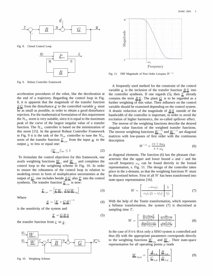
Fig. 11. FRF Magnitude of First Order LowpassW−1
A frequently used method for the constraint of the controlvariableu is the inclusion of the transfer functionR S intothe controller synthesis. If one regards (5), thenT alreadycontains the termR S . The plantG is to be regarded as afurther weighting of this value. Their influence on the controlvariable should be examined depending on the control system.A drastic reduction of the magnitude ofR S outside of thebandwidth of the controller is important, in order to avoid theexcitation of higher harmonics, the so-called spillover effect.
The inverse of the weighting functions describe the desiredsingular value function of the weighted transfer functions.The inverse weighting functionsW −1
sgandW −1
tare diagonal
matrices with low-passes of first order with the continuousdescription
W−1 =εs + aωg
s + ωg
(6)
as diagonal elements. The function (6) has the pleasant char-acteristic that the upper and lower bounda and ε and thecut-off frequencyωg can be found directly in the formalrepresentation, s. Fig. 11. The design of the controller takesplace in the z-domain, so that the weighting functionsW mustbe discretised before. First of allW has been transformed intostate-space representation [16].
W =
−aωg/ε 1
ωg/ε (1 − a/ε) 1/ε
(7)
With the help of the Tustin transformation, which representsa bilinear transformation, the system (7) is discretised atsampling timeT .
W =
2ε−aωgT
2ε+aωgT2ε
2ε+aωgT
2ωgT (ε−a)ε(2ε+aωgT )
ωgT+22ε+aωgT
(8)
In the case of FIVE-BAR only a SISO system is controlled andthus (8) with the appropriate parameters corresponds directlyto the weighting functionsW
sgand W
t. Their state-space
representation for all operating pointsp reads
Wsg,p
=
As,p
Bs,p
Cs,p
Ds,p
(9)

ISARC 2005 6
Fig. 12. Transformed Weighting Scheme without Controller
TABLE I
DIMENSIONS OFSYSTEMS
States Outputs Inputs
Gp
nng ny nu
Wsg,p
nns nu nu
Wt,p
nnt ny ny
Pwu,p
nng + nns + nnt 2ny 2nu + ny
and
Wt,p
=
At,p
Bt,p
Ct,p
Dt,p
. (10)
The composition of the Robust Controller Framework, s.Fig. 9, is carried out by removing the controllerR from theweighting scheme in Fig. 10 and relocate the scheme. Thenew scheme in Fig. 12 matches the blockP
wuin the Robust
Controller Framework, which is built up in the following.From Fig. 12 two equations for the outputsz and e can bederived.
z = G(
Wsg
w d + u)
(11)
e = Wtw r − z (12)
By additive and multiplicative combinations of the state-spacemodelsG , W
sgand W
tfrom (1), (9) and (10) the system
Pwu
is set together.
Pwu
=
At
0 0 Bt
0 0
0 As
0 0 Bs
0
0 BgC
sA
g0 B
gD
sB
g
0 DgC
sC
g0 D
gD
sD
g
Ct
−DgC
s−C
gD
t−D
gD
s−D
g
(13)With the system in- and outputP
wuis linked as follows.
[
ze
]
= Pwu
w r
w d
e
(14)
The dimensions of the individual systems and the completesystemP
wucan be found in Table I. The internal dimensions
of the state-space model in (13) are represented in Table II.Such a weighting scheme is built up for each operating pointp.
TABLE II
DIMENSIONS OFWEIGHTING SCHEME Pwu,p
IN (13)
nnt nns nng ny nu nu
nnt
nns
nng
ny
ny
Here the index was left out due to lack of space. The controllersynthesis is carried out by the SLICOT functionSB10DD foreach operating point after delivery of the systemP
wu,pand
a γ value. Beginning with aγ of 100 this is decreased in upto five iteration steps during successful synthesis.
Thep SISO controllers, which are currently used for FIVE-BAR, have the ordernng + nns + nnt, which corresponds tothe one ofP
wu. The order of the plant is always reduced
to 14 and the two weighting functions have in each case theorder one, which corresponds to a controller order of 16.
The storage of the controllers at run-time takes place in anown state-space model class. For permanent storage on harddisk an own file data base is used.
F. Results
The integrated controller synthesis, presented in this article,is implemented and executable on the QNX computer. In manypractical tests the operability was proven.
The following diagrams are results of a system identificationand a controller synthesis done with that system. The Fig.13 shows the result of the system identification of the plantG in form of a Bode diagram. The broken line shows themeasured frequency response of the real plant, which wascomputed from the time signal under Matlab withtfe. Thecontinuous line shows the frequency response of the systemidentified under QNX. The correlation in amplitude and phaseis very good. The drift, which can be recognized in the phaseresponse, is a result of the anti-aliasing filters adjusted to a cut-off frequency of 100 Hz. A crucial advantage to the formerprocedure, which measured the plants characteristic with aFFT Analyzer, is that these filters are identified directly byidentifying the plant. Former, the filters were added beforethe controller synthesis in Matlab, in order to model the phaseresponse correctly.
The controller designed under QNX is exported to Matlabfor analysis. With the state-space model of the plant thedisturbance rejectionS G could be computed. Together withthe open loop systemG and the inverse weighting functionW −1
sg, used in the synthesis, its singular values are represented
in Fig. 14. In this design nearly only the first eigenfrequencyis suppressed. It can be recognized thatW −1
sgserves as an
upper bound ofS G . Except for the right boundary region,this is fulfilled everywhere.
A measure for the disturbance rejection is the sensitivityS .The sensitivity of the control loop is represented in Fig. 15.In this diagram it can be directly read off, that the maximum

ISARC 2005 7
0 10 20 30 40 50 60 70 80
10−2
10−1
100
Mag
nitu
de (
1)
MeasuredIdentified
0 10 20 30 40 50 60 70 80 90−200
−100
0
100
200
Frequency (Hz)
Pha
se (
degr
ee)
Fig. 13. Measured and Identified Systems FRF
10 20 30 40 50 60 70 80 90 100−40
−30
−20
−10
0
10
20
Mag
nitu
de (
dB)
GSGW
sg−1
Frequency (Hz)
Fig. 14. Singular Values ofG , S G andW−1
sg
10 20 30 40 50 60 70 80 90 100−16
−14
−12
−10
−8
−6
−4
−2
0
2
Mag
nitu
de (
dB)
Frequency (Hz)
Fig. 15. Singular Values of SensitivityS
suppression is -16dB and emerges at a frequency of 12 Hz.The entire process of the measurement, signal processing,
identification, controller synthesis and installation lasts onlyapprox. 25 s on the QNX system, a PC with 2.4 GHz CPUand 512 MB RAM. The measurement already takes 19 s.The identification, controller synthesis and installationare atpresent still called by hand over the command line and needthe remaining 6 s.
IV. CONCLUSION
In this article the method of Robust-Gain-Scheduling forrobust H∞ control of an adaptive system was presented.In order to improve the performance, the knowledge of theposition of the effector was used and the workspace wasdivided according to a Voronoi diagram. The very time-consuming, former procedure for controller synthesis couldbe replaced by a newer and faster one. By the employmentof the SLICOT library it is now possible to run the entiresynthesis process on the realtime computer and thus to shortenits execution time to 25 s at present. With the help of thisprocedure one can react fast and without use of additionalhardware to the sensitivity of the system to be controlled,e.g. after disassembly and assembling. Regarding industrialapplications it is very suitable for practical use of structuralcontrol.
Future work will make the procedure more robust and moreautomated. The parameter setting of the weighting functionsand a more exact analysis of the robustness of the control loopare two of these upcoming topics.
ACKNOWLEDGMENT
This work was funded by the ’Deutsche Forschungsgemein-schaft’ within the framework of the Collaborative ResearchCenter 562 ’Robotic Systems for Handling and Assembly’.
REFERENCES
[1] “Sonderforschungsbereich 562 - robotersysteme fur handhabung undmontage,” TU Braunschweig und Deutsches Zentrum fur Luft-undRaumfahrt e.V., Braunschweig, Finanzierungsantrag, 2003.
[2] J. Steiner and N. Kohn, “Universal communication architecture for high-dynamic robot systems using qnx,” inProc. of ICARCV, Kunming,China, 2004.
[3] E. Breitbach, S. Algermissen, R. Keimer, M. Rose, and C. Stachera,“Adaptive tools in parallel robotics,” inRobotic Systems for Handlingand Assembly, 2nd International Colloquium of the Collaborative Re-search Center 562, ser. Fortschritte in der Robotik, P. Last, C. Budde,and F. M. Wahl, Eds., vol. 9. Braunschweig, Germany: Shaker Verlag,10-11 May 2005, pp. 203–219.
[4] R. Krten, Getting Started with QNX Neutrino 2: A Guide for RealtimeProgrammers. PARSE Software Devices, 2001.
[5] R. Keimer, M. Rose, and S. Algermissen, “Parallelroboter mit adap-tronischer schwingungsunterdruckung am beispiel der versuchsstrukturfunfgelenk,” in Adaptronic Congress, Wolfsburg, April 2003.
[6] S. Algermissen, M. Rose, R. Keimer, and E. Breitbach, “High-speedparallel robots with integrated vibration-suppression for handling andassembly,” in11th Annual International Symposium on Smart Structuresand Materials. San Diego, Kalifornien, USA: SPIE, Marz 2004.
[7] S. Algermissen, M. Rose, and R. Keimer, “Angewandte robuste regelungzur schwingungsunterdruckung am parallelroboter mit adaptronischenkomponenten,” inAdaptronic Congress, Hildesheim, April 2004.
[8] P. Benner, V. Mehrmann, V. Sima, S. V. Huffel, and A. Varga, “Slicot- a subroutine library in systems and control theory,”Applied andComputational Control, Signals, and Circuits, vol. 1, no. 10, pp. 499–539, 1999.

ISARC 2005 8
[9] Slicot sources. [Online]. Available: ftp://wgs.esat.kuleuven.ac.be[10] Clapack sources. [Online]. Available: http://netlib.org/clapack[11] f2c sources. [Online]. Available: http://netlib.org/f2c[12] E. C. Ifeachor and B. W. Jervis,Digital Signal Processing: A Practical
Approach, 2nd ed. Prentice Hall, 2001.[13] W. Favoreel, V. Sima, S. V. Huffel, M. Verhaegen, and B. D.
Moor, “Slicot working note 19986: Subspace model identifica-tion of linear systems in slicot,” European Community BRITEEU-RAM III Thematic Networks Programme NICONET, Tech. Rep.,1998, anonymous ftp from wgs.esat.kuleuven.ac.be in the directorypub/WGS/REPORTS/SLWN19986.ps.Z.
[14] M. S. Tombs and I. Postlethwaite, “Truncated balanced realizationof stable, non-minimal state-space systems,”International Journal ofControl, vol. 46, pp. 1319–1330, 1987.
[15] K. Zhou, J. Doyle, and K. Glover,Robust and Optimal Control. PrenticeHall, 1996.
[16] H. Unbehauen,Regelungstechnik 2: Zustandsregelungen, digitale undnichtlineare Regelsysteme. Vieweg, 1997.