Embed Size (px)
Citation preview
Li et al., Sci. Adv. 2020; 6 : eaay9919 17 April 2020
S C I E N C E A D V A N C E S | R E S E A R C H A R T I C L E
1 of 15
A P P L I E D P H Y S I C S
Under oil open-channel microfluidics empowered by exclusive liquid repellencyChao Li1, Zachary Hite2, Jay W. Warrick2, Jiayi Li2, Stephanie H. Geller2, Victoria G. Trantow2, Megan N. McClean2*, David J. Beebe1,2,3*
Recently, the functionality of under oil open microfluidics was expanded from droplet-based operations to include lateral flow in under oil aqueous channels. However, the resolution of the under oil fluidic channels reported so far is still far from comparable with that of closed-channel microfluidics (millimeters versus micrometers). Here, enabled by exclusive liquid repellency and an under oil sweep technique, open microchannels can now be prepared under oil (rather than in air), which shrinks the channel dimensions up to three orders of magnitude compared to previously reported techniques. Spatial trapping of different cellular samples and advanced control of mass transport (i.e., enhanced upper limit of flow rate, steady flow with passive pumping, and reversible fluidic valves) were achieved with open-channel designs. We apply these functional advances to enable dynamic measurements of dispersion from a pathogenic fungal biofilm. The ensemble of added capabilities reshapes the potential application space for open microfluidics.
INTRODUCTIONOpen microfluidics has been defined as a microfluidic system with at least one solid boundary confining the fluid removed, exposing the fluid either to air (i.e., single liquid phase) or a second fluid (i.e., multiliquid phase) (1–5). Here, we further focus on open microfluidic systems with only a single planar nonfluid boundary (i.e., fluidic manipulations on a flat solid surface). In single liquid–phase open microfluidics, fluid is directly exposed to air, which makes the systems susceptible to evaporation and airborne contamination through the liquid/air interface. Many open microfluidic systems use an oil overlay (i.e., under oil, similar to the oil-overlaid microdroplets used for decades for the in vitro study of early embryo development) (6, 7) to prevent detrimental fluid loss via evaporation and sample contamination. Important advantages of open microfluidics include accessibility, air bubble elimination, and ease of use. The liquid-air or liquid-liquid interface above and surrounding the fluid provides direct physical access to the fluid of interest, e.g., enabling localized interrogation of cellular samples with their biophysics or biochem-istry (3). In addition, without the need to bond to another surface, open microfluidic devices are generally easy to make and easy to use (e.g., elimination of bubble trapping and associated device failures), reducing the adoption barrier to end users (8).
Fundamental to most microfluidic systems (e.g., closed-channel microfluidics) is their ability to control mass transport (e.g., main-taining steady flow, varying flow rate, and turning flow on and off). Until recently, under oil open microfluidics has lacked functionality due to the lack of lateral flow (in fluidic channels). This changed recently with the introduction of lateral flow to under oil open micro-fluidics by several groups (9–12). However, the reported under oil open-channel systems present a number of technical challenges (see detailed discussion in section S1 and figs. S1 and S2) that limit the scope of their geometries and application. Briefly, the reported
techniques form channels via a two-step process whereby the chan-nels are initially filled in air and then subsequently overlaid with oil. If the initial in-air step (before the introduction of an oil overlay) cannot be avoided (e.g., due to the limits of operation), then it restricts the scale of fluidic channels to the millimeter scale due to volume loss via evaporation. Millimeter-scale channels are limited in their ability to spatially and temporally organize cellular samples (e.g., mammalian and bacterial cells are around or less than 10 m) (13) and exhibit limited control of mass transport (e.g., unsteady flow with passive pumping) (11, 14). In addition, open microchannels should also be equipped with the ability to control flow with valves, i.e., to turn flow on and off on demand. Note that under oil open microfluidic systems with static fluidic condition has been demon-strated with ~100-m feature size but not under oil “open-channel” microfluidics with continuous flow. So, the previously reported works such as under oil microchambers (15) were not included in com-parison with this work. Similarly, the genre of hemiwicking-based (e.g., paper or thread) open microfluidic systems (16, 17) was not included or referred to in the discussion because of the fundamen-tally different configuration of fluidic control/dynamics and the lack of overlap in the target areas of application.
Recently, we developed under oil open microfluidics with the extreme wettability of exclusive liquid repellency (ELR) and double ELR (18–20). ELR is a phenomenon observed in solid-liquid-liquid three-phase systems, where a solid surface shows complete repel-lency to a liquid [with contact angle (CA) = 180°] when exposed to a second immiscible liquid. This phenomenon is observed when a par-ticular thermodynamic boundary condition is satisfied (i.e., S/Lcp + Ldp/Lcp ≤ S/Ldp, where is interfacial tension, S is solid, Lcp is liquid of continuous phase, and Ldp is liquid of dispersed phase). ELR en-ables additional fluidic control, robust on-chip cell culture, and im-proved processing of rare cell samples in open aqueous fluid under oil (18). ELR is distinct from other liquid repellent systems with a CA of <180° (i.e., non-ELR), showing no compromise of liquid adhesion on solid surfaces and enabling unique applications. In sys-tems using double ELR, there is selective and complete repellency of two immiscible liquids (e.g., aqueous media and oil) from adjacent surfaces through surface chemistry patterning (Fig. 1A). Fluids are
1Carbone Cancer Center, University of Wisconsin-Madison, Madison, WI 53705, USA. 2Department of Biomedical Engineering, University of Wisconsin-Madison, Madison, WI 53705, USA. 3Department of Pathology and Laboratory Medicine, Uni-versity of Wisconsin-Madison, Madison, WI 53705, USA.*Corresponding author. Email: [email protected] (D.J.B.); [email protected] (M.N.M.)
Copyright © 2020 The Authors, some rights reserved; exclusive licensee American Association for the Advancement of Science. No claim to original U.S. Government Works. Distributed under a Creative Commons Attribution NonCommercial License 4.0 (CC BY-NC).
on June 16, 2020http://advances.sciencem
ag.org/D
ownloaded from

Li et al., Sci. Adv. 2020; 6 : eaay9919 17 April 2020
S C I E N C E A D V A N C E S | R E S E A R C H A R T I C L E
2 of 15
naturally contained on “preferred” surfaces of lower CA, which lowers the free energy of the system. The boundary between surface patterns thus creates a virtual barrier (i.e., an energetic impediment) to fluid expansion from its footprint (i.e., the contact area between the fluid and its preferred surface) (Fig. 1B). Double ELR offers the theoretical maximum virtual barrier to both aqueous fluid and oil with a CA of 180° on their “nonpreferred” surfaces [i.e., oil on glass and media on polydimethylsiloxane (PDMS)] and thus robustly confines the fluids to their preferred surfaces (i.e., oil on PDMS and media on glass). This virtual barrier is important to stabilize the three-phase contact line (TCL) (Fig. 1B). If fluid starts to spread from its original footprint, then it is completely repelled by the non-preferred surface and recedes to the original pattern when the system is allowed to equilibrate. Double ELR allows spontaneous, uncom-promised oil-media separation (without the need for surfactant) and, thus, under oil sweep in open microfluidic design. Under oil sweep is accomplished by simply dragging an aqueous fluid (e.g., cell culture media) across the patterned surface under oil, resulting in a specific volume of media (with or without cells) being sponta-neously dispensed onto the patterned areas (i.e., microchannels or spots) and leaving the background clean with minimal sample loss and device fouling (Fig. 1A, III, and movie S1) (19). In this study, we exploit double ELR and under oil sweep to prepare open micro-channels under oil with high lateral resolution (~30 m in both width and spacing), low profiles (~1 m in height) capable of selective cell trapping, enhanced upper limit of flow rate, steady flow with passive pumping, and fully reversible antibiofouling fluidic valves.
The advances in the under oil technology described in this study allowed us to approach the understudied, but critical, question of
how fungal pathogens disperse from biofilms to cause systemic infection and disease. Systemic fungal infections are often caused by invasive medical devices, such as central venous catheters, that have been colonized by a fungal biofilm (21, 22). Candida yeast spe-cies cause 80 to 90% of these infections, and 21 to 32% of patients who develop invasive Candida infections die. One unique aspect of Candida pathogenesis is the way it disperses into the body to cause infection. Drug-resistant biofilms consisting of hyphal cells embed-ded in an extracellular polymeric substance serve as reservoirs of infection; yeast-like cells dispersed from the biofilm seed metastatic infections and are the main culprits associated with establishment of invasive disease. Clinical evidence suggests that it is the disper-sive capacity of a Candida biofilm that determines virulence (23–25). Despite the importance of dispersion in disease progression, to date, most Candida research has focused on understanding and preventing the formation of biofilms. This is largely because disper-sion is a dynamic and difficult-to-study process that takes place during and after the formation of a biofilm. Compared to in vitro assays to quantify biofilm formation, of which there are many (26), it has been difficult to design in vitro assays capable of measuring the dispersive capacity of a biofilm. These assays need to allow monitoring, separation, collection, and quantification of dispersed cells throughout the biofilm life cycle without device fouling by hyphal or dispersed cells. Ideally, this could be performed under conditions that mimic the physiological microenvironment (e.g., blood flow, hypoxia, and interaction between multiple cell types) and be amenable to miniaturization to allow for high-throughput screening. The under oil open microfluidic system provides an avenue toward creating such a device as it allows (i) versatile control
Fig. 1. Double-ELR under oil open microchannels. (A) Schematic of the fabrication workflow. (I) Substrate (e.g., glass) was treated with PDMS-silane for the surface chemistry required to completely repel aqueous media (or media for short) with Young’s CA = 180° (i.e., in ELR) under oil (silicone oil, 5 cSt). (II) A PDMS stamp was con-structed using an SU-8 master and used for surface patterning by O2 plasma treatment. (III) After surface patterning, the microchannels were overlaid with oil first and then filled with media by under oil sweep. Fluid can be delivered to or removed from the microchannels by active or passive pumping. Cellular samples can be seeded onto or harvested from designated areas via pipetting. Scale bar, 5 mm for the inset image of an under oil microchannel. UV, ultraviolet. (B) Representative features of the under oil open-channel microfluidic system in cell culture. In the proposed solid-liquid-liquid system, PDMS glass– patterned surface (solid with surface chemistry con-trast, i.e., PDMS for background and glass for microchannels), oil and media consist of the three phases that give double ELR. The liquids (oil and media) spontaneously take and get robustly confined on their preferred surfaces (i.e., oil on PDMS and media on glass). Leaking or invasion of the liquids to the nonpreferred surfaces (i.e., oil on glass and media on PDMS), that is, movement of the solid-oil-media TCL (purple solid lines), is safeguarded by the double- ELR virtual barrier attributed to the difference of CA [ = oil-in-media on glass − oil-in-media on PDMS for oil (yellow dashed line) and = media-in-oil on PDMS − media-in-oil on glass for media (blue dashed line), where oil-in-media on glass = 180°, media-in-oil on PDMS = 180°, oil-in-media on PDMS = 71.3°, and media-in-oil on glass = 60.4°] (18, 19).
on June 16, 2020http://advances.sciencem
ag.org/D
ownloaded from
Li et al., Sci. Adv. 2020; 6 : eaay9919 17 April 2020
S C I E N C E A D V A N C E S | R E S E A R C H A R T I C L E
3 of 15
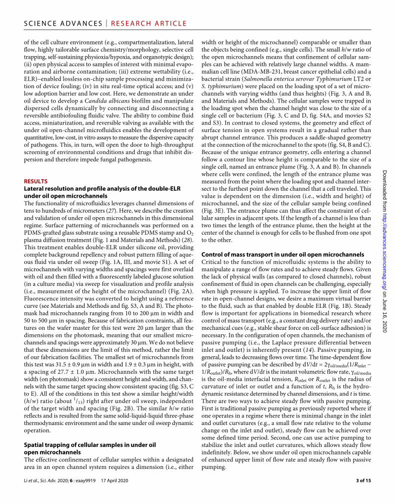
of the cell culture environment (e.g., compartmentalization, lateral flow, highly tailorable surface chemistry/morphology, selective cell trapping, self-sustaining physioxia/hypoxia, and organotypic design); (ii) open physical access to samples of interest with minimal evapo-ration and airborne contamination; (iii) extreme wettability (i.e., ELR)–enabled lossless on-chip sample processing and minimiza-tion of device fouling; (iv) in situ real-time optical access; and (v) low adoption barrier and low cost. Here, we demonstrate an under oil device to develop a Candida albicans biofilm and manipulate dispersed cells dynamically by connecting and disconnecting a reversible antibiofouling fluidic valve. The ability to combine fluid access, miniaturization, and reversible valving as available with the under oil open-channel microfluidics enables the development of quantitative, low-cost, in vitro assays to measure the dispersive capacity of pathogens. This, in turn, will open the door to high-throughput screening of environmental conditions and drugs that inhibit dis-persion and therefore impede fungal pathogenesis.
RESULTSLateral resolution and profile analysis of the double-ELR under oil open microchannelsThe functionality of microfluidics leverages channel dimensions of tens to hundreds of micrometers (27). Here, we describe the creation and validation of under oil open microchannels in this dimensional regime. Surface patterning of microchannels was performed on a PDMS-grafted glass substrate using a reusable PDMS stamp and O2 plasma diffusion treatment (Fig. 1 and Materials and Methods) (28). This treatment enables double-ELR under silicone oil, providing complete background repellency and robust pattern filling of aque-ous fluid via under oil sweep (Fig. 1A, III, and movie S1). A set of microchannels with varying widths and spacings were first overlaid with oil and then filled with a fluorescently labeled glucose solution (in a culture media) via sweep for visualization and profile analysis (i.e., measurement of the height of the microchannel) (Fig. 2A). Fluorescence intensity was converted to height using a reference curve (see Materials and Methods and fig. S3, A and B). The photo-mask had microchannels ranging from 10 to 200 m in width and 50 to 500 m in spacing. Because of fabrication constraints, all fea-tures on the wafer master for this test were 20 m larger than the dimensions on the photomask, meaning that our smallest micro-channels and spacings were approximately 30 m. We do not believe that these dimensions are the limit of this method, rather the limit of our fabrication facilities. The smallest set of microchannels from this test was 31.5 ± 0.9 m in width and 1.9 ± 0.3 m in height, with a spacing of 27.7 ± 1.0 m. Microchannels with the same target width (on photomask) show a consistent height and width, and chan-nels with the same target spacing show consistent spacing (fig. S3, C to E). All of the conditions in this test show a similar height/width (h/w) ratio (about 1/13) right after under oil sweep, independent of the target width and spacing (Fig. 2B). The similar h/w ratio reflects and is resulted from the same solid-liquid-liquid three-phase thermodynamic environment and the same under oil sweep dynamic operation.
Spatial trapping of cellular samples in under oil open microchannelsThe effective confinement of cellular samples within a designated area in an open channel system requires a dimension (i.e., either
width or height of the microchannel) comparable or smaller than the objects being confined (e.g., single cells). The small h/w ratio of the open microchannels means that confinement of cellular sam-ples can be achieved with relatively large channel widths. A mam-malian cell line (MDA-MB-231, breast cancer epithelial cells) and a bacterial strain (Salmonella enterica serovar Typhimurium LT2 or S. typhimurium) were placed on the loading spot of a set of micro-channels with varying widths (and thus heights) (Fig. 3, A and B, and Materials and Methods). The cellular samples were trapped in the loading spot when the channel height was close to the size of a single cell or bacterium (Fig. 3, C and D, fig. S4A, and movies S2 and S3). In contrast to closed systems, the geometry and effect of surface tension in open systems result in a gradual rather than abrupt channel entrance. This produces a saddle-shaped geometry at the connection of the microchannel to the spots (fig. S4, B and C). Because of the unique entrance geometry, cells entering a channel follow a contour line whose height is comparable to the size of a single cell, named an entrance plume (Fig. 3, A and B). In channels where cells were confined, the length of the entrance plume was measured from the point where the loading spot and channel inter-sect to the furthest point down the channel that a cell traveled. This value is dependent on the dimension (i.e., width and height) of microchannel, and the size of the cellular sample being confined (Fig. 3E). The entrance plume can thus affect the constraint of cel-lular samples in adjacent spots. If the length of a channel is less than two times the length of the entrance plume, then the height at the center of the channel is enough for cells to be flushed from one spot to the other.
Control of mass transport in under oil open microchannelsCritical to the function of microfluidic systems is the ability to manipulate a range of flow rates and to achieve steady flows. Given the lack of physical walls (as compared to closed channels), robust confinement of fluid in open channels can be challenging, especially when high pressure is applied. To increase the upper limit of flow rate in open-channel designs, we desire a maximum virtual barrier to the fluid, such as that enabled by double ELR (Fig. 1B). Steady flow is important for applications in biomedical research where control of mass transport (e.g., a constant drug delivery rate) and/or mechanical cues (e.g., stable shear force on cell-surface adhesion) is necessary. In the configuration of open channels, the mechanism of passive pumping (i.e., the Laplace pressure differential between inlet and outlet) is inherently present (14). Passive pumping, in general, leads to decreasing flows over time. The time-dependent flow of passive pumping can be described by dV/dt = 2oil/media(1/Rinlet − 1/Routlet)/Rh, where dV/dt is the instant volumetric flow rate, oil/media is the oil-media interfacial tension, Rinlet or Routlet is the radius of curvature of inlet or outlet and a function of t, Rh is the hydro-dynamic resistance determined by channel dimensions, and t is time. There are two ways to achieve steady flow with passive pumping. First is traditional passive pumping as previously reported where if one operates in a regime where there is minimal change in the inlet and outlet curvatures (e.g., a small flow rate relative to the volume change on the inlet and outlet), steady flow can be achieved over some defined time period. Second, one can use active pumping to stabilize the inlet and outlet curvatures, which allows steady flow indefinitely. Below, we show under oil open microchannels capable of enhanced upper limit of flow rate and steady flow with passive pumping.
on June 16, 2020http://advances.sciencem
ag.org/D
ownloaded from

Li et al., Sci. Adv. 2020; 6 : eaay9919 17 April 2020
S C I E N C E A D V A N C E S | R E S E A R C H A R T I C L E
4 of 15
First, straight microchannels (10 mm in length with varying widths) were prepared to evaluate their maximum flow rate (Qmax) with active pumping (Fig. 4A and Materials and Methods). The vol-umetric flow rate (Q) of fluid (incompressible, Newtonian, and in laminar flow with no-slip boundary) in a channel is described by Poiseuille’s law as P = RhQ, where P is the pressure drop and Rh is the hydrodynamic resistance. The maximum P that can be applied to an open channel is defined by the maximum Laplace
pressure differential between the inlet and outlet of a given condi-tion. A P higher than the defined maximum causes failure of liquid confinement. As discussed above, to maintain a constant P and, thus, a steady flow, a syringe pump can be used to stabilize the curvature of the microdroplets by adding volume to the inlet and removing the same volume from the outlet. Under the tested condition, we achieved a Qmax of 2.5 ± 1.0 l/min for microchannels 241 m in width, 60 ± 7.1 l/min for those 553 m in width, and ~6 ml/min for
Fig. 2. Parallel microchannels for lateral resolution and profile analysis. (A) Microchannels with an inlet (on left) and outlet (on right) spot and varying target widths and spacings. For each condition, a fluorescent image of the parallel microchannels (top), a profile plot (lower left), and a three-dimensional surface plot (lower right) are included. Region of interest (ROI) [1750 m (orthogonal to the channels) × 1900 m (parallel to the channels), applying to all conditions for profile analysis] is denoted with a yellow box on each fluorescent image. The peaks and valleys are labeled on the profile plots with black dots. The height (converted from intensity using a reference curve; fig. S3, A and B) for each microchannel is averaged along the 1900-m edge of the ROI. Note that the irregularly shaped outline seen on a few of the inlet spots was received from the PDMS stamps (i.e., a defect introduced to the stamp during punching a hole for the O2 plasma diffusion treatment) rather than under oil sweep. Scale bar, 5 mm. (B) Height/width ratio plots for each spacing condition. The dashed line shows a linear fitting with 95% confidence interval (conf. int.) of the slope.
on June 16, 2020http://advances.sciencem
ag.org/D
ownloaded from

Li et al., Sci. Adv. 2020; 6 : eaay9919 17 April 2020
S C I E N C E A D V A N C E S | R E S E A R C H A R T I C L E
5 of 15
those 1048 m in width in steady flow, showing a power-law depen-dence of log10(Qmax) on 5.22log10(w) (Fig. 4, B and C, tables S1 and S2, and fig. S5). To the best of our knowledge, these high flow rates have not been previously achieved in open-channel systems and are enabled here by the robust virtual barrier provided by double
ELR. The range of flow rates obtained is comparable with blood flow rates for various vessel diameters (e.g., ~4 l/min in venous blood vessels with a diameter of about 100 m) (29) and thus ex-tends the use of open microfluidic systems in biomedical research, e.g., to study the invasion of microbial pathogens through the
Fig. 3. Spatial trapping of cellular samples in under oil open microchannels. (A) Green fluorescent protein (GFP)–labeled breast cancer epithelial cells (MDA-MB-231) were added to the loading spot (3 mm in diameter) of a set of microchannels (10 mm in length with varying widths). The stitched images of microchannels (the column on the left) contain alternating bright field and fluorescent images with a yellow box indicating the ROI of the magnified images (the two columns on the right). Scale bars, 5 mm for the stitched images and 500 m for the magnified images. (B) Yellow fluorescent protein (YFP)–labeled S. typhimurium was inoculated to the loading spot of another set of microchannels (10 mm in length with varying widths). Scale bars, 500 m for the magnified images and 50 m for the inset showing a close-up of single bacteria. The microchannels (on the bright field images), the outlet spot (on the fluorescent images), and the entrance plume (on the fluorescent images) are labeled with dashed lines to improve visualization. (C and D) Height of the microchannels is calculated by taking 1/13 of the channel width (h/w ratio established in Fig. 2). Plots display the channel height and width where confinement occurs (the red dashed lines) along with the measured size of MDA-MB-231 (averaged diameter in the solid green line and SD in the gray envelope for 13.5 ± 5.5 m) and S. typhimurium (averaged length in yellow solid line and SD in the gray envelope for 6.8 ± 1.2 m). (E) The length of the entrance plume as a function of the channel width to a given size of the particle being confined (MDA-MB-231 plotted in green and S. typhimurium in yellow).
on June 16, 2020http://advances.sciencem
ag.org/D
ownloaded from

Li et al., Sci. Adv. 2020; 6 : eaay9919 17 April 2020
S C I E N C E A D V A N C E S | R E S E A R C H A R T I C L E
6 of 15
blood-brain barrier (30). Note that a specific law to precisely predict the fluidic dynamics from the under oil open microchannels may need to resort to computational simulation due to the inherent com-plexity, e.g., the slip boundary at the oil-media interface and the evo-lution of geometry of the microchannels after under oil sweep (fig. S5).
Sustained release of a reagent is of great importance in cell biol-ogy (31), e.g., to study pharmacodynamics of drugs or intercellular signaling. For a given P, a sufficiently high Rh is necessary to reach a small flow rate and, thus, steady flow with passive pumping over a defined time period (as discussed above). Rh can be controlled by varying the dimensions of the channel, i.e., either by making the channel longer or by reducing the cross-sectional area. With a given resistance, the channel length needs to be increased exponentially to offset the change in the cross-sectional area of the channel (e.g., Rh ∝ l/w4 for a channel with a rectangular cross section; table S1). So, to establish a steady flow with passive pumping across a short distance (e.g., a few hundred micrometers, a typical distance in which capil-lary exchange occurs in vivo) (13), a reduced cross-sectional area with a given aqueous fluid is necessary; however, existing open
fluidic channels are dimensionally limited to the millimeter scale, which makes it difficult to achieve steady flow with passive pump-ing in a given small distance. The high lateral resolution and the small cross-sectional profiles from the double-ELR under oil open microchannels (Fig. 4C, inset) enable steady flows across a distance of a few hundred micrometers. Shown here are flow rates and profile plots of mass transport between microdroplets obtained by passively pumping fluorescent dye through microchannels vary-ing in width and length (Fig. 4, D to M, and Materials and Meth-ods). Microchannels with and without extracellular matrix (ECM) were compared. Equal initial volumes were added to the inlet and outlet spots using under oil sweep, and then, a small volume (0.5 l) was loaded to the inlet spot to begin passive pumping (table S1). Among the tested conditions, the lowest flow rate obtained was ~13 pl/min for a 42-m-wide and 422-m-long microchannel, with an ECM coating. In comparison, the microchannels without ECM coating showed a higher flow rate especially for channels with a smaller Rh (i.e., larger channel width and/or smaller channel length). Because of the small flow rate compared with the volume loaded to the
Fig. 4. Flow control with active and passive pumping in under oil open microchannels. (A) Schematic shows the setup of a microchannel with active pumping (i.e., connected with a syringe pump). P is the pressure drop between the inlet and outlet spots across the microchannel (see Materials and Methods for detailed calculation). (B) Microscopic images of the microchannels 10 mm in length with a channel width of >100 m for volumetric flow rate (Q) test with active pumping. Scale bar, 5 mm. (C) Qmax as a function of channel width. The flow rate was controlled by a syringe pump in steady flow. Qmax was recorded at the point the fluid started to accumulate on the inlet spot (indicating pumping rate > Qmax). The dashed line shows the fitting with Qmax in logarithm. Inset: Schematic of the cross section (a circular segment, orthogonal to the flow) of the under oil microchannel, where h and w are the channel height and width, respectively. The dashed line box shows the rectangular cross section used in the calculation of flow rates (table S1). (D) Percentage of dye delivered versus time by passive pumping from the microchannels with a channel width of <100 m and without extracellular matrix (ECM) coating. The fluorescence intensity (on the outlet spot) was converted to the percentage of volume delivered (see Materials and Meth-ods for detailed calculation). The dashed lines show the linear fitting. (E and F) Profile plots of the fastest and slowest microchannel in (D). The gray envelope denotes the position of the microchannel between the inlet and outlet spot. (G and H) Microscopic images (from left to right: bright field, 560 nm/607 nm (Excitation/Emission, or Ex/Em), and 485 nm/505 nm (Ex/Em) for 0 and 2.5 hours of dye loading) of the microchannels in (E) and (F). Scale bars, 1 mm. (I to M) Same analysis as (D) to (H) but for microchannels with ECM (collagen I) coating.
on June 16, 2020http://advances.sciencem
ag.org/D
ownloaded from

Li et al., Sci. Adv. 2020; 6 : eaay9919 17 April 2020
S C I E N C E A D V A N C E S | R E S E A R C H A R T I C L E
7 of 15
inlet spot, the steady flow can be maintained for hours at least by passive pumping alone.
Spatiotemporal control using double-ELR reversible antibiofouling fluidic valvesOpen channels present a unique challenge in the design of revers-ible valves due to the lack of physical walls, whereby a mechanism capable of connecting, disconnecting, and reconnecting fluid flow on demand could be easily deployed. Here, we report the design of reversible antibiofouling valves for open channels (Fig. 5 and Mate-rials and Methods). Earlier, a reconfigurable liquid bridge (i.e., a droplet of fluid connecting two separated spots) enabled by double ELR was introduced for spatiotemporal control of cell coculture under oil (19). By simply adding volume to or removing volume from the liquid bridge, connection or disconnection can be achieved reversibly. The same principle can be applied to open channels for a reversible valve, but a more complicated parameter space must be considered to control the mechanical stability and connection dynamics of the liquid bridge. Here, valves with three different geometries—straight-channel, Bowman’s capsule (i.e., a cup-like sack seen in mammalian kidney), and Pokeball (i.e., a spherical device in the Pokemon franchise)—are studied (Fig. 5A). Similar to the process for creating open microchannels under oil described above, here, the process is initiated by adding a certain volume of media (or the initial volume, Vinitial) to the valve to form a liquid bridge connecting the upstream and downstream channels. Because of passive pumping, a net volume [V = (Vout − Vin) ≈ Vout with Vin ≈ 0 under the tested condition, where Vout is the volume removed or pumped out of the liquid bridge and Vin is the volume added or pumped into the liquid bridge] is removed (or pumped out) from the liquid bridge to the outlet spot. Once the volume in the liquid bridge reaches a critical point (i.e., the minimum amount of liquid required to maintain the connection of the liquid bridge, Vcritical), the liquid bridge opens at the ELR gap. Vcritical is determined by the geometry and size of the ELR gap. Briefly, a larger ELR gap requires a larger Vcritical to maintain the connection of the liquid bridge and vice versa. The connection time of a valve is defined as the time to reduce Vinitial to Vcritical by passive pumping (i.e., the amount of time a valve stays connected, tconnection). A fixed Vinitial (3 l) was ap-plied for all testing conditions, considering the effect of Vinitial on tconnection (i.e., the larger the initial volume, the longer the valve stays connected and vice versa). For a given Vinitial, tconnection is determined by Q of passive pumping and Vcritical. As discussed in Fig. 4, Q can be affected by P (in this case, the Laplace pressure differential between the valve and the outlet spot) and/or Rh (e.g., the channel width or length). A larger Vcritical (e.g., a valve with a larger ELR gap) results in a shortened tconnection for a given Q. The volume pumped in and out of a valve (i.e., Vin and Vout), and thus, the connection time (tconnection) of a valve in passive pumping can be predicted by integrating the instant volumetric flow rate (dV/dt) over time (t). Note that if steady flow across the microchannel is maintained (e.g., by active pumping), setting Vin = Vout and thus V = 0, then the valves can stay connected indefinitely.
The first design was a straight-channel valve (Fig. 5B). The straight- channel valves exhibited poor mechanical stability of the liquid bridge against external disturbance, e.g., vibration during transfer of the device (fig. S6). The liquid bridge easily slid off the valve, causing failure (i.e., unpredictable disconnection) of the valve. The lack of an energetically favorable resting spot also led to a randomly located
center of the liquid bridge (i.e., random position of the liquid bridge relative to the ELR gap), which caused stochastic asymmetrical disconnection of the liquid bridge and thus poor predictability of tconnection.
To improve mechanical stability and reproducibility of the liq-uid bridge, a valve in the shape of Bowman’s capsule was designed (Fig. 5, C and E) (32). The valve consists of a center spot on the upstream channel (creating a droplet anchor point), a horseshoe- shaped area (or horseshoe for short) on the downstream channel (to stabilize the liquid bridge), and an ELR gap in between the center spot and the horseshoe. The Bowman’s capsule valves showed a subs-tantially improved resistance to disturbance due to the increased footprint of the liquid bridge and a consistent position of the ELR gap on the liquid bridge due to the optimized geometry (fig. S6). tconnection of this valve design was investigated by varying the chan-nel width (500 m versus 200 m) and the size of the ELR gap. Valves connected to 500-m-wide microchannels disconnected subs-tantially faster than the ones on 200-m-wide microchannels (shortening tconnection from hours to only a few minutes) attributed to a larger Q of passive pumping for the wider channels. Changing the size of the ELR gap (by modifying the sizes of the center spot and the horseshoe) shows no notable influence on tconnection for 500-m-wide microchannels due to a large Q. In contrast, reducing the size of the ELR gap substantially increases tconnection for 200-m-wide microchannels. Note that tconnection can be manually adjusted on demand by directly adding volume to or removing volume from the liquid bridge, e.g., with a pipet (movie S4).
To further increase tconnection (e.g., for a use where long-term connection of the valve from one loading of Vinitial is needed), we designed a valve taking a shape reminiscent of a Pokeball, with a pair of horseshoes facing toward each other separated by an ELR gap (Fig. 5, D and F). Different from Bowman’s capsule valves, changing the size of the ELR gap on Pokeball valves (by modifying the sizes of the center spot and the two horseshoes, and the spacing between the two horseshoes) shows clear influence on tconnection regardless the channel width. Note that the spacing between the two horseshoes has a dominant influence on tconnection when it is small. Theoretically, the double-ELR valves have no limit on reversibility (i.e., number of open/close operations) unless the surface chemistry is changed (e.g., by physical damage of the surface). In this experi-ment, the double-ELR valves showed no decay after at least 20 on/off cycles tested with a suspension of beads in a protein-rich media (Fig. 5G). Without double-ELR, the non-ELR valves showed failures and device fouling from both filling of the microchannels and dis-connection of the valve (Fig. 5H and movie S5). The media randomly stuck to the background (i.e., the unpatterned area) permanently once it touched down the surface due to the compromised repellency (or non-ELR with a CA of <180°).
Spatiotemporal control in fungal dispersionTo explore the potential of the proposed system for studying the dis-persion of fungal yeast species, we first tested the ability of C. albicans cells to complete the biofilm life cycle in isolated under oil spots (fig. S7 and movie S6). The results captured three distinguishable stages in the development of a fungal biofilm (26), i.e., early (0 to 4 hours), growth of planktonic yeast cells (PYCs) into hyphae; intermediate (4 to 8 hours), further hyphal growth and development of dispersed yeast cells (DYCs) on hyphae; and mature (8 to 18 hours), release of DYCs into media. We were able to observe settling of DYCs onto
on June 16, 2020http://advances.sciencem
ag.org/D
ownloaded from

Li et al., Sci. Adv. 2020; 6 : eaay9919 17 April 2020
S C I E N C E A D V A N C E S | R E S E A R C H A R T I C L E
8 of 15
Fig. 5. Double-ELR reversible antibiofouling fluidic valves. (A) Schematics show the three types of valves (i.e., straight-channel valve, Bowman’s capsule valve, and Pokeball valve) designed on an under oil open microchannel (white areas on the black background) and the opening mechanism. The microchannels are 7 mm in length with two different widths (500 and 200 m), with an inlet (1 mm in diameter) and an outlet spot (3 mm in diameter) indicated by red circles. The flow direction (red arrow) is from the inlet spot to the outlet spot. The valve separates the microchannel by introducing an ELR gap (the black area between the upstream and downstream chan-nels) at a position close to the center of the microchannel. The liquid bridge covers an area shown as translucent blue (top view). The area covered by the liquid bridge consists of both preferred surface (microchannels filled with media, blue) and nonpreferred surface (PDMS covered with oil, yellow) with a boundary defined by the TCL (purple solid line). Because of double ELR, the liquid bridge is anchored to its preferred surface (blue) and can recede freely from the nonpreferred surface on a thin layer of oil (yellow overlapped with translucent blue). When the volume of the liquid bridge decreases, it opens by pinching at the ELR gap following a path denoted by the black arrows. Formatting for valve labeling X-YYY-ZZZ-AAAA-CCC (see Materials and Methods). (B) Straight-channel valves show poor mechanical stability and random liquid bridge placement. (C) Bowman’s capsule valves on 500-m-wide microchannels. (D) Pokeball valves on 500-m-wide microchannels. (E) Bowman’s capsule valves on 200-m-wide microchannels. (F) Pokeball valves on 200-m-wide microchannels. (G) Reversibility and antibiofouling of the double-ELR valves. No decay was observed after 20 on/off cycles. (H) Failure of non-ELR valves and device fouling. Scale bars, 5 mm.
on June 16, 2020http://advances.sciencem
ag.org/D
ownloaded from

Li et al., Sci. Adv. 2020; 6 : eaay9919 17 April 2020
S C I E N C E A D V A N C E S | R E S E A R C H A R T I C L E
9 of 15
the bottom of the under oil spot. We observed a marked difference in DYCs depending on the initial inoculation density of PYCs. At low inoculation density, a large amount of DYCs started to release into the media and settle to the bottom of the spot at 8 hours. Coun-terintuitively, at the high inoculation density, we could observe almost no DYCs at the bottom of the spot. Our ability to distinguish differences in DYCs between inoculation conditions and time points suggests that under oil droplets could allow rapid screening of genetic mutants and environmental conditions for dispersion pro-motion and dispersion inhibition.
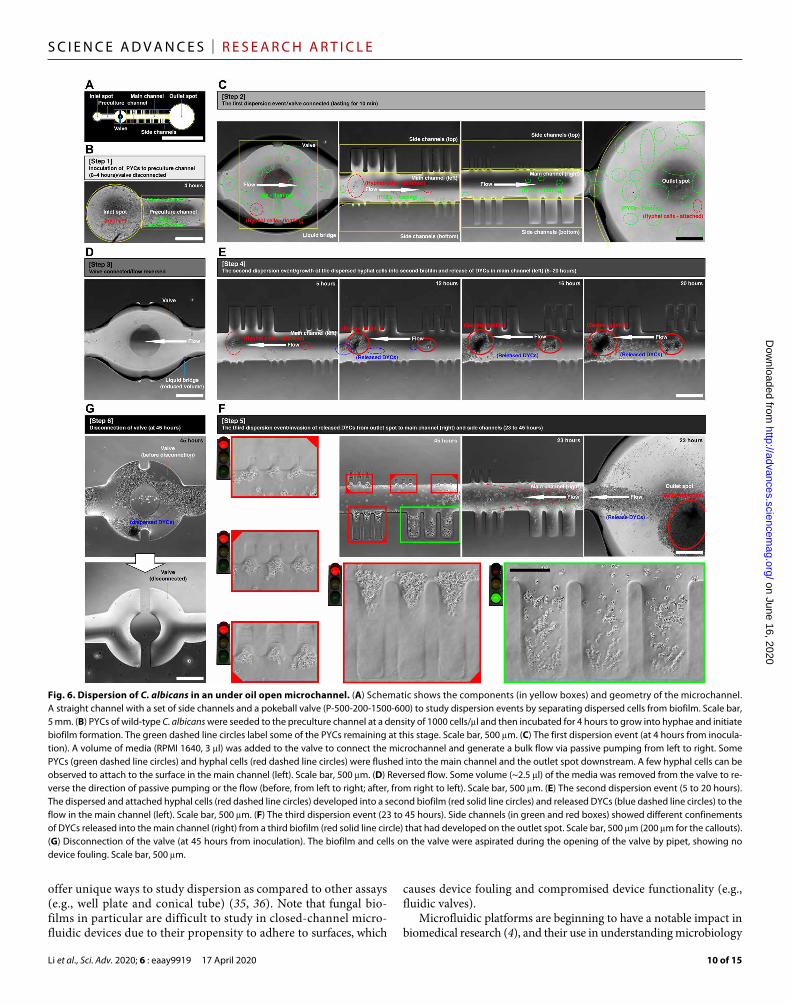
We further developed a microchannel capable of static early development of PYCs into a biofilm, followed by dispersion events with distinct flow regimes and selective trapping of DYCs. The de-vice consists of a straight channel laced with a set of side channels (in varying widths) and a Pokeball valve (Fig. 6A and fig. S8). Three dispersion events were successfully monitored on the same device by manipulating the flow environment. The first dispersion event—PYCs were inoculated into the preculture channel and grown for 4 hours, while the valve was disconnected, which resulted in an early hyphal stage of the PYCs and initiation of biofilm formation (Fig. 6B). Connection of the valve induced flow (from left to right) that resulted in the movement of PYCs and some clumps of hyphal cells from the preculture channel to the main channel and the outlet spot down-stream (Fig. 6C and movie S7). By initially isolating PYCs in a preculture channel without flow, we can control the timing and environment of the early development of PYCs into a biofilm be-fore creating a distinct dispersion event by connection of the valve. In the second dispersion event, the first dispersion event was termi-nated by reversing the flow (Fig. 6D and movie S8). The dispersed hyphal cells grew into a second biofilm in the main channel and released DYCs into the flow at about 8 hours after connection of the valve (Fig. 6E and movie S9). In the third dispersion event, the side channels of different widths showed distinct confinement of DYCs released from a third biofilm grown on the outlet spot based on channel height (Fig. 6F and movie S10). After the dispersion events and on day 2, the valve was successfully disconnected, showing no compromise of the double ELR (Fig. 6G). Disconnection of the valve allowed for complete separation of the original biofilm de-veloped in the preculture channel from the dispersed cells (and the subsequent biofilms) in the main channel, enabling further end point assays.
DISCUSSIONFree physical access, minimal clogging issues, and a low adoption barrier are traits of open microfluidic systems that differ from closed-channel microfluidics, making it an appealing branch of microfluidics to end users by limiting the amount of training in engineering and relying less on access to specialized infrastructures. However, because of technical limitations (e.g., scale and precision of the channel dimensions, attainable flow rates, and spatiotemporal control of fluids/reagents), the full potential of open microfluidics has not been realized. These limitations have stymied the broad adoption of open microfluidic technology. Recent works have shown major advances to the regime of under oil open microfluidics (11, 12), introducing lateral flow to this genre and pushing the boundary closer to closed-channel microfluidics. Among the reported accom-plishments are direct liquid printing on chemically homogeneous surfaces, liquid filling on patterned surfaces with surface chemistry
contrast, and three-dimensional printing of fluidic bridges. However, the gap between open and closed channels remains due to limited channel resolution (at millimeter scale) and limited control of mass transport. To finally transition open microfluidics to a functional regime comparable to closed-channel microfluidics, an enabling technology is required to remove the inherent obstacles of reducing the scale of open fluidic channels. The extreme wettability of ELR and double ELR provides a path to expanding the capabilities of under oil open microfluidics in such a way that they begin to match that of traditional closed-channel microfluidics.
The critical capabilities demonstrated here (i.e., high channel resolution and advanced control of mass transport) begin to bridge the performance gap between open- and closed-channel micro-fluidics. First, double ELR offers a solution to the technical challenges and allows channels to be filled by directly sweeping reagents under oil and, thus, at a substantially smaller scale than previously reported (dozens of micrometers versus millimeters). This mitigates volume loss due to evaporation, a notable complication of open microfluidic devices that has to date severely limited their functionality. The micrometer scale achieved in this study does not approach the theoretical limits but, rather, was the limit of readily available pattern-ing techniques. Thus, submicrometer open fluidic channels can be envisioned with improved surface patterning techniques (e.g., e-beam lithography). Second, the double-ELR technology creates a strong virtual fluid boundary, allowing for robust liquid confinement and much higher flow rates than possible in previous under oil devices. Last, double ELR enables fully reversible antibiofouling fluidic valves to be integrated into open channels for an on-demand control of the flow.
The fungal dispersion assay we proposed here demonstrates the unique capability of categorizing dispersed fungal cells by quantity, size, and/or shape, which may be important in understanding the virulence and pathogenicity of fungi (33). One can envision using the under oil open-channel microfluidic system to explore the parameter space controlling dispersion. The effect of genetic varia-tion and genetic mutations on dispersive capacity could be measured by comparing the relative amount of dispersed cells to biofilm bio-mass retained in the initial seeding (or preculture) chamber. The sudden release of dispersed cells at around 8 hours suggests that nutrient and/or quorum sensing may play a role in regulating dispersion. This has been theorized but never rigorously tested (34). The difference in biofilm formation and DYCs between the low and high inoculation densities also implicates quorum sensing. The ability to control the timing of valve connection and, therefore, ini-tiation of flow and subsequent dispersion means that dispersive capacity can be measured throughout the lifetime of a biofilm and as nutrient availability and quorum sensing evolve with time. Flow rate can be modulated to understand how physical factors modulate dispersion. Short-channel sustained release can be used to study drug response over varied concentrations and time. The size-selection function from the side channels could be used to selectively trap and follow the subsequent development of dispersed cells. It also offers a microfilter function with open-channel design, e.g., to study the synchronized behavior among different colonies with only solu-ble factors. Interfacing parallel chambers with high-throughput robotics and existing libraries of Candida mutants, isolates, and drug collections vastly expand the capability to screen for factors that inhibit the dispersive capacity and, therefore, virulence of a fungal biofilm infection. The capabilities of under oil open microfluidics
on June 16, 2020http://advances.sciencem
ag.org/D
ownloaded from
Li et al., Sci. Adv. 2020; 6 : eaay9919 17 April 2020
S C I E N C E A D V A N C E S | R E S E A R C H A R T I C L E
10 of 15
offer unique ways to study dispersion as compared to other assays (e.g., well plate and conical tube) (35, 36). Note that fungal bio-films in particular are difficult to study in closed- channel micro-fluidic devices due to their propensity to adhere to surfaces, which
causes device fouling and compromised device functionality (e.g., fluidic valves).
Microfluidic platforms are beginning to have a notable impact in biomedical research (4), and their use in understanding microbiology
Fig. 6. Dispersion of C. albicans in an under oil open microchannel. (A) Schematic shows the components (in yellow boxes) and geometry of the microchannel. A straight channel with a set of side channels and a pokeball valve (P-500-200-1500-600) to study dispersion events by separating dispersed cells from biofilm. Scale bar, 5 mm. (B) PYCs of wild-type C. albicans were seeded to the preculture channel at a density of 1000 cells/l and then incubated for 4 hours to grow into hyphae and initiate biofilm formation. The green dashed line circles label some of the PYCs remaining at this stage. Scale bar, 500 m. (C) The first dispersion event (at 4 hours from inocula-tion). A volume of media (RPMI 1640, 3 l) was added to the valve to connect the microchannel and generate a bulk flow via passive pumping from left to right. Some PYCs (green dashed line circles) and hyphal cells (red dashed line circles) were flushed into the main channel and the outlet spot downstream. A few hyphal cells can be observed to attach to the surface in the main channel (left). Scale bar, 500 m. (D) Reversed flow. Some volume (~2.5 l) of the media was removed from the valve to re-verse the direction of passive pumping or the flow (before, from left to right; after, from right to left). Scale bar, 500 m. (E) The second dispersion event (5 to 20 hours). The dispersed and attached hyphal cells (red dashed line circles) developed into a second biofilm (red solid line circles) and released DYCs (blue dashed line circles) to the flow in the main channel (left). Scale bar, 500 m. (F) The third dispersion event (23 to 45 hours). Side channels (in green and red boxes) showed different confinements of DYCs released into the main channel (right) from a third biofilm (red solid line circle) that had developed on the outlet spot. Scale bar, 500 m (200 m for the callouts). (G) Disconnection of the valve (at 45 hours from inoculation). The biofilm and cells on the valve were aspirated during the opening of the valve by pipet, showing no device fouling. Scale bar, 500 m.
on June 16, 2020http://advances.sciencem
ag.org/D
ownloaded from

Li et al., Sci. Adv. 2020; 6 : eaay9919 17 April 2020
S C I E N C E A D V A N C E S | R E S E A R C H A R T I C L E
11 of 15
is expanding to mimic the natural habitats of microbes (37). Re-cent works have shown that simple changes in the dimensions (i.e., size, interspace) of microbial habitats can cause wide-ranging effects on both the function and fate of the microorganisms (e.g., the stability of a multispecies bacterial community) (38) or the effi-ciency of evolution to acquire antimicrobial resistance (39). Because of free on-chip access and a low adoption barrier, under oil systems are a promising platform for biologists who desire precise control of microenvironmental cues. Here, we have demonstrated a new class of under oil open-channel microfluidics that substantially expands its functionality. Empowered by extreme wettability, i.e., ELR and double ELR, the gap between open- and closed-channel microfluidics is narrowed, offering new opportunities for the application of open microfluidics. These expanded capabilities allow for the precise manipulation of various cellular samples and advanced control of mass transport in open fluid. This technology has many potential and easy-to-explore applications within biomedical research, e.g., biofilm dynamics, antimicrobial drug screening, and host-microbe interactions.
MATERIALS AND METHODSFabrication of PDMS-grafted glassPremium microscope slide (Fisherfinest, 3″ × 1″ × 1 mm; Thermo Fisher Scientific, 12-544-1) or chambered coverglass (1 well, no. 1.5 borosilicate glass, 0.13 to 0.17 mm thick; Thermo Fisher Scientific, 155360) was treated first with O2 plasma (Diener Electronic Femto, Plasma Surface Technology) at 60 W for 3 min and then moved to a vacuum desiccator (Bel-Art F420220000, Thermo Fisher Scientific, 08-594-16B) for vapor phase deposition. PDMS-silane (1,3- dichlorotetramethylsiloxane; Gelest, SID3372.0) (about 10 l per device) was vaporized under pumping for 3 min and then condensed onto glass substrate under vacuum at room temperature for 30 min. The PDMS-grafted surface was thoroughly rinsed with ethanol (anhydrous, 99.5%) and deoinized (DI) water and then dried with nitrogen for use (Fig. 1A, I).
Fabrication of PDMS stampPhoto mask was designed with Adobe Illustrator (Ai) and then sent to a service (Fineline Imaging) for printing. Standard photolithog-raphy was applied to make a master that contains all the microchannel features. A 4″ silicon wafer (University Wafer, ID 1116) was thor-oughly cleaned and rinsed with acetone, isopropanol, and DI water and then dried with nitrogen before use. The wafer was baked on a hotplate (EchoTherm HP30, Torrey Pines Scientific) at 95°C for 30 min before spin coating of a photoresist (SU-8 50, MicroChem, Y131269 1000 L 1GL). SU-8 was coated evenly onto the silicon wafer on a spin coater (Spincoater Model P6700, Specialty Coating Systems) with a speed setting (ramp to 500 rpm at 100 rpm/s and hold for 10 s, ramp to 2000 rpm at 300 rpm/s and hold for 30 s) that produces a thickness of about 50 m. After prebaking on a hotplate at 65°C for 6 min, followed by 95°C of softbaking for 20 min, the photoresist layer hardened. Photo mask was placed on top of the silicon wafer and exposed to 365 nm of ultraviolet (OmniCure Series 1000) at 350 mJ/cm2 for about 30 min. To reduce stresses built up by traditional postexposure baking, the wafer was placed on a hotplate and ramped from room temperature to 95°C over approximately 5 min. Once the hotplate reached 95°C, it was turned off and allowed to cool down to room temperature. Uncross-linked SU-8 was washed
off in propylene glycol monomethyl ether acetate (ReagentPlus, ≥99.5%; Sigma-Aldrich, 484431) on a shaker (SeaStar Digital Orbital Shaker) for 90 min to develop the features. The develop-ment was checked by rinsing the wafer with isopropanol, and a fully developed wafer showed no white residue, was washed with DI water, and was dried with nitrogen. Last, PDMS stamps were made by pouring a degassed (about 20 min using a vacuum desiccator) silicone precursor and curing agent mixture (SYLGARD 184, Silicone Elastomer Kit, Dow, 04019862) in 10:1 mass ratio onto the master and cured on a hotplate at 80°C for 4 hours. The PDMS stamps were stripped off with tweezers and punched with holes (Miltex Biopsy Punch with Plunger, Ted Pella, 15110) at the inlet and outlet of a microchannel for the following O2 plasma diffusion treatment (Fig. 1A, II).
Preparation of under oil open microchannelsThe PDMS-grafted glass was masked by a punched PDMS stamp and then treated with O2 plasma at 60 W for 3 min. After surface patterning, the PDMS stamp was removed by tweezers and stored in a clean space for reuse. The glass slides were held in a plate [Nunc four-well tray, polystyrene (PS), nontreated sterile, Thermo Fisher Scientific, 267061] and overlaid with oil (silicone oil, 5 cSt; Sigma- Aldrich, 317667). The chambered coverglass was directly overlaid with oil. Silicone oil is the “right” oil to give the extreme wettability (i.e., ELR) based on our previous work (18). Tests on extraction of vital biomolecules (e.g., mRNA) from under oil and the quantita-tive polymerase chain reaction results in another previous work showed no obvious cargo loss during the processing (19). The microchannels were filled with a media, Dulbecco’s modified Eagle’s medium (Thermo Fisher Scientific, 11960051) + 10% fetal bovine serum (Thermo Fisher Scientific, 10437010), by under oil sweep before use (Fig. 1A, III). The same media (unless otherwise speci-fied) was used in preparation of all of the solution and suspension used in this study. An antistatic gun (Zerostat 3 Milty, EMS 60610) was used to generate perturbation during sweep and to facilitate the displacement of oil by media (19).
Hand-printed channels on unpatterned substrates in different environments (in air versus under oil)Using a pipet and a variety of tips (1- to 200-l large orifice, 1 to 200 l, and 1 to 10 l), channels were drawn with a fluorescently labeled glucose 2-(N-(7-nitrobenz-2-oxa-1,3-diazol-4-yl)amino)-2-deoxy-glucose (2-NBDG) (Thermo Fisher Scientific, N13195) (0.2 mM in media) on untreated glass slides and PS culture dishes (Corning Falcon Bacteriological Petri Dishes, 351007, 60 mm by 15 mm; Thermo Fisher Scientific, 08-757-100B). One set of surfaces was performed in air, and another was performed under oil. Tips did not come into contact with the surface being patterned, and where necessary, the antistatic gun was used. Imaging of the hand-printed channels was performed on a fluorescent microscope (Nikon Eclipse Ti) with the bright field and 485-nm/505-nm Excitation/Emission (Ex/Em) (exposure time, 2 s) channels (fig. S1).
Under oil dry channelsA set of straight channels was prepared on a PDMS-grafted glass slide with Kapton tape mask and O2 plasma treatment (fig. S2). The channels were overlaid with oil without filling of any aqueous fluid. DI water was premixed with food dye (Assorted Food Color & Egg Dye, McCormick) and added to each channel on the loading spot by
on June 16, 2020http://advances.sciencem
ag.org/D
ownloaded from
Li et al., Sci. Adv. 2020; 6 : eaay9919 17 April 2020
S C I E N C E A D V A N C E S | R E S E A R C H A R T I C L E
12 of 15
pipet. The loading was stopped when bulging of the fluid occurred. The wetting length was directly measured on the image.
Measurement of the dimensions of under oil open microchannels(i) A reference curve was created from measuring a serially diluted 2-NBDG solution (from 20 to 0.1, 0.05, 0.02, 0.01, 0.005, and 0.002 mM in media) on a Nikon Eclipse Ti. The 2-NBDG solution was added to a set of under oil spots (2 mm in diameter) for 2 l per spot, making a spherical cap-shaped microdroplet with a height of ~970 m (fig. S3, A and B). Fluorescent images were taken using the 485-nm/525-nm (Ex/Em) channel (exposure time, 2 s) with no lookup table applied. The peak intensity in a small area (30 m in diameter) close to the center of the microdroplets was measured in ImageJ (Set ROI–Measure– Analyze). Background intensity was measured using the same method and was subtracted from the peak intensity. The measured intensity was then converted to height equivalent to 2 mM 2-NBDG solution, which was used on the microchannels for profile analysis in the fol-lowing. (ii) The microchannels were prepared 5 mm in length with varying target widths (10, 25, 50, 100, and 200 m) and spacings (50, 100, 200, and 500 m). Fluorescent images were taken immedi-ately after the microchannels were filled with the solution (i.e., 2 mM 2-NBDG solution) by under oil sweep (Fig. 2 and fig. S3, C to E). The profile was extracted and quantified in ImageJ (plot profile) with a region of interest (ROI) of 1750 m (orthogonal to the chan-nels) × 1900 m (parallel to the channels). R/RStudio was used to find the peaks of the background subtracted profiles (‘peakPick’ package). Thresholding of the profiles was used to detect the edges of the channels. Width versus height was plotted and fit with the ‘lm’ function of R to estimate slopes and slope confidence intervals.
Spatial trapping of cellular samples in under oil open microchannelsTwo sets of under oil microchannels (10 mm in length and 3 mm in diameter for both the inlet and outlet spots) with variable channel widths were prepared to study the confinement of mammalian cells and bacteria. The microchannels were kept in an on-stage incubator (Bold Line, Okolab) with the following condition: 37°C, 95% rela-tive humidity (RH), 5% CO2. The mammalian cell line used was green fluorescent protein (GFP)–labeled MDA-MB-231 [American Type Culture Collection (ATCC), HTB-26], and the strain of bacte-ria was yellow fluorescent protein (YFP)–labeled S. typhimurium (ATCC, 14028) (40). The mammalian cells were prepared at 1000 cells/l, and bacteria were prepared at 2.5 × 10⁵ cells/l. A specific volume of the cell stock (5 l for MDA-MB-231 and 1 l for S. typhimurium) was pipetted to the loading spot at the inlet. Images and videos were recorded on a Nikon Eclipse Ti with bright field and 485-nm/525-nm (Ex/Em) (exposure time, 1 s) channels after the system was stabilized (5 min after sample loading) (Fig. 3). The av-erage area of an MDA-MB-231 cell was obtained by analyzing the fluorescent channel images in ImageJ. The fluorescent images were thresholded using the default algorithm and processed with the Analyze Particles function. The average area was converted to an average diameter (13.5 ± 5.5 m) by assuming that the cells are spherical. The size of S. typhimurium (6.8 ± 1.2 m in length and 2.1 ± 0.3 m in width) was measured in ImageJ by manually drawing ROI lines along the length and width of a set of cells and then aver-aged. Last, a duplicate of the under oil microchannels was tested with fluorescent microbeads [1 m in diameter, 1 to 50 dilution in
media (fig. S4A), and 2 l added to the loading spot) (Interfacial Dy-namics, Fluorescent Nile Red CML Latex, 2-FN-1000). Images and videos were recorded on a Nikon Eclipse Ti with bright field and 560-nm/607-nm (Ex/Em) (exposure time, 1 s) channels after the sys-tem was stabilized (5 min after sample loading).
Measurement of the maximum flow rate with active pumpingA syringe pump (Fusion 4000, Chemyx) was fitted with two syringes (1-ml Luer-Lok, BD, 309628), one to infuse media into the inlet spot (Dinlet = 1 mm) and another to withdraw from the outlet spot (Doutlet = 3 mm). Both syringes had 18-gauge (inlet = outlet = 1 mm) blunt tip needles (SAI Infusion Technologies, B18-150) attached with 18-gauge polytetrafluoroethylene tubing (Component Supply, SWTT-18-C) leading to the microchannels. The needle on the inlet for fluid delivery was treated with PDMS-silane to obtain double ELR (with the same treatment as PDMS-grafted glass was performed), stabilizing TCL and thus limiting the capillary wicking of media along the outer wall of the needle. The needle on the outlet was untreated. The inlet tub-ing was cleared of air by depressing the syringe. The inlet needle was held perpendicularly above the inlet spot at a height of 1 mm (hinlet = 1 mm). The outlet needle was placed in the same way as the inlet but with 3 mm (houtlet = 3 mm) between the outlet spot and the needle. The syringe pump was set to start at a small flow rate (0.1 to 1 l/min, depending on the channel width tested), and the microchannel was allowed to equilibrate for at least 1 min. Flow rates were then stepped up every 30 s (0.2 l/min for 200-m-wide microchannels, 2 l/min for 500-m-wide microchannels, and 100 l/min for 1000-m-wide microchannels). The maximum flow rate was deter-mined by recording the point at which accumulation of aqueous fluid at the inlet occurred (Fig. 4). Each replicate was performed with a new microchannel. Images of the microchannels tested were taken on a Nikon Eclipse Ti with 2-NBDG solution (2 mM in media) using the bright field and 485-nm/525-nm (Ex/Em) (exposure time, 2 s) channels. Under the tested condition, the inlet microdroplet takes a torus shape to minimize the radius of curvature [Rinlet = 2/(1/Rinlet-1 + 1/Rinlet-2) = 0.67 mm, where Rinlet-1 = hinlet, Rinlet-2 = hinlet/2], and the outlet microdroplet is the shape of a spherical cap with a radius of curvature Routlet = 1.88 mm (defined by Doutlet and houtlet). P is defined by the Laplace pressure differential between the inlet and outlet spots (i.e., 2oil/media/Rinlet − 2oil/media/Routlet, where oil/media is the oil-media interfacial tension, about 41.8 mN/m at 25°C) (table S1) (18). The radius of curvature of the microchannel (Rchannel) at t0 (i.e., immediately after the microchannels filled with a solution by under oil sweep) can be calculated as Rchannel = 2/(1/Rchannel ⊥ + 1/Rchannel ∥) = 2 Rchannel ⊥ (table S2 and fig. S5), where Rchannel ⊥ (de-fined by channel width, w, and height, h) and Rchannel ∥ (∞) are the radius of curvature from the cross section of the microchannel per-pendicular (i.e., a circular segment) and parallel to the flow (i.e., a rectangle). Je’Xperiment (JEX) was used to measure the width, w, and length, l, of each connecting channel. A power-law dependence of Q on w was estimated (i.e., Q ∝ w^a, fitting data to find “a”). This was performed in R/RStudio by plotting log10(Q) versus log10(w) with the “lm” function to calculate the slope parameter, “a = 5.22.”
Measurement of the steady flow with passive pumpingMicrochannels (2 mm in diameter for both inlet and outlet spots, 500 or 200 m in length, and 100, 50, 25, or 10 m in width) were
on June 16, 2020http://advances.sciencem
ag.org/D
ownloaded from
Li et al., Sci. Adv. 2020; 6 : eaay9919 17 April 2020
S C I E N C E A D V A N C E S | R E S E A R C H A R T I C L E
13 of 15
prepared on PDMS-grafted glass slides. The four-well tray holding the slides under oil was transferred to the on-stage incubator (37°C, 95% RH, 5% CO2). The microchannels were filled with media pre-mixed either with dextran (1 mM in media) (Texas Red, MW 70,000, Fisher Scientific, D1864) or collagen I [2 mg/ml; neutralized with 20% Hepes (2×) phosphate-buffered saline (PBS) solution in 1:1 volume ratio, further diluted with PBS in 1:1 volume ratio, and then mixed with 5% fluorescently labeled red collagen] (Rat Tail Collagen I, Thermo Fisher Scientific, A1048301). A total of 0.5 l (Vloaded) of 2-NBDG solution (2 mM in media) was loaded to the inlet spot (on the right) and then pumped to the outlet spot [with an initial volume on both the inlet and outlet spots of 0.24 l from un-der oil sweep (Vsweep)]. The radius of curvature of the inlet and outlet microdroplet can be known as Rinlet = 1.35 mm and Routlet = 3.33 mm (defined by spot diameter and the volume on each spot and assum-ing that the microdroplets take a spherical cap-shaped geometry), respectively (table S1). Given that flow in the microchannels domi-nates diffusion (Pe >> 1), diffusive exchange was ignored. The dye loaded on the inlet spot mixed rapidly and subsequently flew very slowly to the outlet spot. Therefore, we expect the maximum volume that can be delivered (Vdeliverd.max) to the outlet spot is 50% of Vloaded (i.e., Vdeliverd.max = 0.25 l). The dye was loaded at each microchannel in the following order according to Q from slowest to fastest: (width/length) 10 m/500 m to 10 m/200 m to 25 m/500 m to 25 m/200 m. Time lapse was set up on a Nikon Eclipse Ti to scan multiple spots (eight in total) in xy plane using bright field, 485-nm/525-nm (Ex/Em) (exposure time, 1 s), and 560-nm/670-nm (Ex/Em) (exposure time, 400 ms) channels for 12 hours with 5-min interval. Image analysis was performed in JEX to measure the width, w, and length, l, of each connecting channel and to quantify fluorescence intensities on the inlet and outlet spots and throughout the connecting channel (41, 42). The fluorescence intensities from the inlet and outlet spots were analyzed in R/RStudio and normalized to a range of 0 to 1. The percentage of volume (of the dye) delivered to the outlet spot was converted from the fluorescence intensities using the formula Vdelivered.max/Vloaded × Vdelivered.max/(Vdelivered.max + Vsweep) × Ioutlet/Iinlet, where Iinlet and Ioutlet are the averaged fluorescence intensity mea-sured on the inlet and outlet spot, respectively, and plotted versus time (Fig. 4).
Double-ELR reversible antibiofouling fluidic valvesMicrochannels (1-mm-diameter inlet spot, 3-mm-diameter outlet spot, 7 mm in length, and 500 or 200 m in width) with three different types of valves (straight-channel, Bowman’s capsule, and Pokeball) were prepared on PDMS-grafted glass slides (Fig. 5). The micro-channel between the valves with 2000-m horseshoe patterns (Bowman’s capsule and Pokeball) and the outlet spot is 2 mm in length. For all other conditions, the microchannel is 3 mm in length. Formatting for valve labeling X-YYY-ZZZ-AAAA-CCC. X denotes the valve type (S, straight-channel; B, Bowman’s capsule; P, Pokeball), YYY is the channel width, ZZZ is the size of the ELR gap (on straight-channel and Pokeball valves), AAAA is the size of horse-shoe (on Bowman’s capsule and Pokeball valves), and CCC is the size of the center spot (on Bowman’s capsule and Pokeball valves). All of the values are target dimensions in micrometers. (i) The 500-m-wide microchannels were tested on a stereoscope (Olympus, SZX12). Images and videos were collected with a charge-coupled device camera (Exo Labs Focus) connected to an iPad, and samples were lit with a secondary light source (Dolan Jenner, Fiber-Lite
Series 180). Each valve was loaded with 3 l of a suspension containing fluorescent microbeads (1 m in diameter; Interfacial Dynamics, Fluorescent Nile Red CML Latex, 2-FN-1000) at a 1:50 dilution in media. The antistatic gun method was used to help distribute the microdrop on the valve. Video was recorded immediately after the valve was connected. Valves were used for multiple videos and therefore required washing with media between tests. Approx-imately 100 l of media were dispensed on top of the microchannel and manually flushed and removed by pipet. (ii) The 200-m-wide microchannels were tested on a Nikon Eclipse Ti using time lapse (10 hours with 10-min intervals). Three microliters of 2-NBDG solution (2 mM in media) was placed on each valve. Time lapse was started immediately after all valves were connected and imaged using the 485-nm/ 525-nm (Ex/Em) channel (exposure time, 2 s).
Mechanical stability testing of the valvesSix sets of microchannels (i.e., all three valve types: straight- channel, Bowman’s capsule, and Pokeball with both 500- and 200-m channel widths) were patterned onto PDMS-grafted glass slides. The slides were held and overlaid with oil in a four-well tray (5 ml per well). The tray was then placed on a rocking mixer (Vari-Mix Platform Mixer, Fisher Scientific) at a frequency of 17 cycles/min with 3 l of media placed on each valve in a set. Video was recorded, and the mixer was turned on for 15 to 20 s. Valves were connected and imaged for each set separately (fig. S6).
Spatiotemporal control on the dispersion of C. albicansC. albicans SC5314 cells were grown overnight in a roller drum (250 rpm) at 37°C in yeast extract peptone dextrose (YPD) (1% yeast extract; BD), 2% peptone (BD), 2% dextrose (Thermo Fisher Scientific) supplemented with uridine (80 g/ml; Acros Organics). To explore Candida life cycle checkpoints, two concentrations of the seeding cells (7000 cells/l versus 70 cells/l) were tested. The cell stock (vortexed) was added to a set of under oil spots (2 mm in diameter) for 2 l per spot. Time lapse was taken on a Nikon Eclipse Ti using bright field for 18 hours with 5-min intervals. High- magnification images and z-stacks were recorded at 18 hours as the end point (fig S7). For the dispersion test, the concentration of the cell stock for under oil seeding was 1000 cells/l. The microchannel was prepared on a PDMS-grafted chambered coverglass (fig. S8). The device was then overlaid with oil, transferred to the on-stage incu-bator (37°C, 95% RH, 5% CO2) and filled with a media, RPMI 1640 (Gibco, Thermo Fisher Scientific, 11875093) by under oil sweep. One microliter of the cell stock (vortexed) was added to the inlet spot and the preculture channel and then incubated for 4 hours with the valve disconnected. The primary biofilm was imaged using bright field on a Nikon Eclipse Ti at 4 hours. Then, 3 l of RPMI 1640 was added to the valve to connect the preculture channel with the main channel, initiating movement of cells or hyphae from the primary biofilm to downstream into the main channel via bulk flow and passive pumping. After about 10 min, 2.5 l of the vol-ume at the valve was manually removed to reverse the direction of flow to stop further dispersion of the primary biofilm while main-taining a bulk flow (reversed) in the main channel. Time lapse was recorded at ×6 magnification from 4 to 45 hours with multiple lo-cations, i.e., inlet spot and preculture channel, valve, left main chan-nel and right main channel with side channels, and part of the outlet spot. Images were taken at 45 hours on a Nikon Eclipse Ti for end point using bright field. Last, the valve was disconnected by
on June 16, 2020http://advances.sciencem
ag.org/D
ownloaded from
Li et al., Sci. Adv. 2020; 6 : eaay9919 17 April 2020
S C I E N C E A D V A N C E S | R E S E A R C H A R T I C L E
14 of 15
removing the volume along with the biomass (biofilm and cells) in the liquid bridge with pipet (and a 1- to 200-l large orifice tip) (Fig. 6).
SUPPLEMENTARY MATERIALSSupplementary material for this article is available at http://advances.sciencemag.org/cgi/content/full/6/16/eaay9919/DC1
View/request a protocol for this paper from Bio-protocol.
REFERENCES AND NOTES 1. B. Zhao, J. S. Moore, D. J. Beebe, Surface-directed liquid flow inside microchannels.
Science 291, 1023–1026 (2001). 2. B. P. Casavant, E. Berthier, A. B. Theberge, J. Berthier, S. I. Montanez-Sauri, L. L. Bischel,
K. Brakke, C. J. Hedman, W. Bushman, N. P. Keller, D. J. Beebe, Suspended microfluidics. Proc. Natl. Acad. Sci. U.S.A. 110, 10111–10116 (2013).
3. G. V. Kaigala, R. D. Lovchik, E. Delamarche, Microfluidics in the “open space” for performing localized chemistry on biological interfaces. Angew. Chem. Int. Ed. Engl. 51, 11224–11240 (2012).
4. E. K. Sackmann, A. L. Fulton, D. J. Beebe, The present and future role of microfluidics in biomedical research. Nature 507, 181–189 (2014).
5. J. Berthier, K. A. Brakke, E. Berthier, Open microfluidics. , (2016). 6. R. L. Brinster, A method for in vitro cultivation of mouse ova from two-cell to blastocyst.
Exp. Cell Res. 32, 205–208 (1963). 7. J. C. Tae, E. Y. Kim, W. D. Lee, S. P. Park, J. H. Lim, Sterile filtered paraffin oil supports in vitro
developmental competence in bovine embryos comparable to co-culture. J. Assist. Reprod. Genet. 23, 121–127 (2006).
8. D. I. Walsh III, D. S. Kong, S. K. Murthy, P. A. Carr, Enabling microfluidics: From clean rooms to makerspaces. Trends Biotechnol. 35, 383–392 (2017).
9. C. Li, M. Boban, S. A. Snyder, S. P. R. Kobaku, G. Kwon, G. Mehta, A. Tuteja, Paper-based surfaces with extreme wettabilities for novel, open-channel microfluidic devices. Adv. Funct. Mater. 26, 6121–6131 (2016).
10. C. Li, M. Boban, A. Tuteja, Open-channel, water-in-oil emulsification in paper-based microfluidic devices. Lab Chip 17, 1436–1441 (2017).
11. E. J. Walsh, A. Feuerborn, J. H. R. Wheeler, A. N. Tan, W. M. Durham, K. R. Foster, P. R. Cook, Microfluidics with fluid walls. Nat. Commun. 8, 816–825 (2017).
12. W. Feng, Y. Chai, J. Forth, P. D. Ashby, T. P. Russell, B. A. Helms, Harnessing liquid-in-liquid printing and micropatterned substrates to fabricate 3-dimensional all-liquid fluidic devices. Nat. Commun. 10, 1095–1104 (2019).
13. F. R. Balkwill, M. Capasso, T. Hagemann, The tumor microenvironment at a glance. J. Cell Sci. 125, 5591–5596 (2013).
14. G. M. Walker, D. J. Beebe, A passive pumping method for microfluidic devices. Lab Chip 2, 131–134 (2002).
15. C. Soitu, A. Feuerborn, A. N. Tan, H. Walker, P. A. Walsh, A. A. Castrejón-Pita, P. R. Cook, E. J. Walsh, Microfluidic chambers using fluid walls for cell biology. Proc. Natl. Acad. Sci. U.S.A. 115, 5926–5933 (2018).
16. M. M. Gong, D. Sinton, Turning the page: Advancing paper-based microfluidics for broad diagnostic application. Chem. Rev. 117, 8447–8480 (2017).
17. P. Mostafalu, M. Akbari, K. A. Alberti, Q. Xu, A. Khademhosseini, S. R. Sonkusale, A toolkit of thread-based microfluidics, sensors, and electronics for 3D tissue embedding for medical diagnostics. Microsyst Nanoeng. 2, 16039 (2016).
18. C. Li, J. Yu, J. Schehr, S. M. Berry, T. A. Leal, J. M. Lang, D. J. Beebe, Exclusive liquid repellency: An open multi-liquid-phase technology for rare cell culture and single-cell processing. ACS Appl. Mater. Interfaces 10, 17065–17070 (2018).
19. C. Li, J. Yu, P. Paine, D. S. Juang, S. M. Berry, D. J. Beebe, Double-exclusive liquid repellency (double-ELR): An enabling technology for rare phenotype analysis. Lab Chip 18, 2710–2719 (2018).
20. C. Li, D. J. Niles, D. S. Juang, J. M. Lang, D. J. Beebe, Automated system for small-population single-particle processing enabled by exclusive liquid repellency. SLAS Technol. 24, 535–542 (2019).
21. L. J. Douglas, L. Julia Douglas, Candida biofilms and their role in infection. Trends Microbiol. 11, 30–36 (2003).
22. E. M. Kojic, R. O. Darouiche, Candida infections of medical devices. Clin. Microbiol. Rev. 17, 255–267 (2004).
23. P. Uppuluri, A. K. Chaturvedi, A. Srinivasan, M. Banerjee, A. K. Ramasubramaniam, J. R. Köhler, D. Kadosh, J. L. Lopez-Ribot, Dispersion as an important step in the Candida albicans biofilm developmental cycle. PLOS Pathog. 6, e1000828 (2010).
24. N. Robbins, P. Uppuluri, J. Nett, R. Rajendran, G. Ramage, J. L. Lopez-Ribot, D. Andes, L. E. Cowen, Hsp90 governs dispersion and drug resistance of fungal biofilms. PLOS Pathog. 7, e1002257 (2011).
25. P. Uppuluri, J. L. Lopez-Ribot, Go forth and colonize: Dispersal from clinically important microbial biofilms. PLOS Pathog. 12, e1005397 (2016).
26. J. Chandra, D. M. Kuhn, P. K. Mukherjee, L. L. Hoyer, T. McCormick, M. A. Ghannoum, Biofilm formation by the fungal pathogen Candida albicans: Development, architecture, and drug resistance. J. Bacteriol. 183, 5385–5394 (2001).
27. G. M. Whitesides, The origins and the future of microfluidics. Nature 442, 368–373 (2006). 28. D. J. Guckenberger, E. Berthier, E. W. K. Young, D. J. Beebe, Fluorescence-based
assessment of plasma-induced hydrophilicity in microfluidic devices via Nile Red adsorption and depletion. Anal. Chem. 86, 7258–7263 (2014).
29. C. E. Riva, J. E. Grunwald, S. H. Sinclair, B. L. Petrig, Blood velocity and volumetric flow rate in human retinal vessels. Invest. Ophthalmol. Vis. Sci. 26, 1124–1132 (1985).
30. E. Mairey, A. Genovesio, E. Donnadieu, C. Bernard, F. Jaubert, E. Pinard, J. Seylaz, J. C. Olivo-Marin, X. Nassif, G. Duménil, Cerebral microcirculation shear stress levels determine Neisseria meningitidis attachment sites along the blood-brain barrier. J. Exp. Med. 203, 1939–1950 (2006).
31. J. J. S. Kuo, D. T. Chiu, Controlling mass transport in microfluidic devices. Annu. Rev. Anal. Chem. 4, 275–296 (2011).
32. J. Ju, J. Warrick, D. J. Beebe, A cell programmable assay (CPA) chip. Lab Chip 10, 2071–2076 (2010).
33. L. Wang, X. Lin, Morphogenesis in fungal pathogenicity: Shape, size, and surface. PLOS Pathog. 8, e1003027 (2012).
34. J. R. Blankenship, A. P. Mitchell, How to build a biofilm: A fungal perspective. Curr. Opin. Microbiol. 9, 588–594 (2006).
35. C. J. Nobile, E. P. Fox, N. Hartooni, K. F. Mitchell, D. Hnisz, D. R. Andes, K. Kuchler, A. D. Johnson, A histone deacetylase complex mediates biofilm dispersal and drug resistance in Candida albicans. MBio 5, e01201-14 (2014).
36. P. Uppuluri, A. K. Chaturvedi, Design of a simple model of Candida albicans biofilms formed under conditions of flow: Development, architecture, and drug resistance. Mycopathologia 168, 101–109 (2009).
37. R. Rusconi, M. Garren, R. Stocker, Microfluidics expanding the frontiers of microbial ecology. Annu. Rev. Biophys. 43, 65–91 (2014).
38. H. J. Kim, J. Q. Boedicker, J. W. Choi, R. F. Ismagilov, Defined spatial structure stabilizes a synthetic multispecies bacterial community. Proc. Natl. Acad. Sci. U.S.A. 105, 18188–18193 (2008).
39. Q. Zhang, G. Lambert, D. Liao, H. Kim, K. Robin, C. K. Tung, N. Pourmand, R. H. Austin, Acceleration of emergence of bacterial antibiotic resistance in connected microenvironments. Science 333, 1764–1767 (2011).
40. S. M. Douglas, L. M. Chubiz, W. R. Harcombe, F. Marty Ytreberg, C. J. Marx, Parallel mutations result in a wide range of cooperation and community consequences in a two-species bacterial consortium. PLOS ONE 11, e0161837 (2016).
41. J. W. Warrick, A. Timm, A. Swick, J. Yin, Tools for single-cell kinetic analysis of virus-host interactions. PLOS ONE 11, e0145081 (2016).
42. J. W. Warrick, E. W. K. Young, E. G. Schmuck, K. W. Saupe, D. J. Beebe, High-content adhesion assay to address limited cell samples. Integr. Biol. 5, 720–727 (2013).
43. J. Eggers, Nonlinear dynamics and breakup of free-surface flows. Rev. Mod. Phys. 69, 865–930 (1997).
44. E. Ueda, P. A. Levkin, Patterned superhydrophobic surfaces. Soft Matter Ser. 182–222 (2016).
45. H. Bruus, Theoretical Microfluidics (Oxford Univ. Press on Demand, 2008). 46. S. Yedgar, D. B. Weinstein, W. Patsch, G. Schonfeld, F. E. Casanada, D. Steinberg,
Viscosity of culture medium as a regulator of synthesis and secretion of very low density lipoproteins by cultured hepatocytes. J. Biol. Chem. 257, 2188–2192 (1982).
47. V. R. N. Telis, J. Telis-Romero, H. B. Mazzotti, A. L. Gabas, Viscosity of aqueous carbohydrate solutions at different temperatures and concentrations. Int. J. Food Prop. 10, 185–195 (2007).
48. F. Carrasco, E. Chornet, R. P. Overend, J. Costa, A generalized correlation for the viscosity of dextrans in aqueous solutions as a function of temperature, concentration, and molecular weight at low shear rates. J. Appl. Poly. Sci. 37, 2087–2098 (1989).
49. R. B. Bird, Transport phenomena. Appl. Mech. Rev. 55, R1–R4 (2002).
Acknowledgments: We thank M. Livingston and P. Mcminn (Beebe group) for the training on photolithography, J. Ayuso (Beebe group) for the early inspiring discussion on mass transport using under oil microchannels, M. Gong (Beebe group) for the supply of the GFP-labeled breast cancer cells (MDA-MB-231), R. Clark (Venturelli group) and the Harcombe group at the University of Minnesota, Twin Cities for the supply of the YFP-labeled bacteria (S. typhimurium), and M. Humayun (Beebe group) for the discussion on the no-slip boundary conditions. We thank the BME design project from 2018 and 2019 for the Fall and Spring design teams vetting the under oil device for studying the dispersion of C. albicans. Fall design team: J. Li,
on June 16, 2020http://advances.sciencem
ag.org/D
ownloaded from
Li et al., Sci. Adv. 2020; 6 : eaay9919 17 April 2020
S C I E N C E A D V A N C E S | R E S E A R C H A R T I C L E
15 of 15
V. G. Trantow, X. He, A. Mandepally, B. Pernsteiner, and K. Masters; https://bmedesign.engr.wisc.edu/projects/f18/biofilm_dispersion_junior/. Spring design team: V. G. Trantow, J. Li, S. Schirber, A. Omidfar, and J. Puccinnelli; https://bmedesign.engr.wisc.edu/projects/s19/biofilm_dispersion_junior/. Funding: This work was supported by NSF EFRI-1136903-EFRI-MKS, NIH R01 EB010039 BRG, NIH R01 CA185251, NIH R01 CA186134, NIH R01 CA181648, NIH R21 AI135166, EPA H-MAP 83573701, and American Cancer Society IRG-15-213-51. M.N.M. holds a Career Award at the Scientific Interface from the Burroughs Wellcome Fund. Author contributions: C.L. designed the research. C.L., Z.H., J.L., and S.H.G. performed the experiments. C.L., J.W.W., and Z.H. analyzed the raw data and prepared data visualization. All authors wrote the manuscript and revised it. Competing interests: D.J.B. holds equity in BellBrook Labs LLC, Tasso Inc., Stacks to the Future LLC, Lynx Biosciences LLC, Onexio Biosystems LLC, Turba LLC, and Salus Discovery LLC. D.J.B. is a consultant for Abbott Laboratories. D.J.B. and C.L. are inventors on a patent application related to this work filed by WARF, 62/868378, filed 28 June 2019. D.J.B. is an inventor on a patent application related to
this work filed by WARF, 62/868296, filed 28 June 2019. D.J.B. and C.L., are inventors on a patent application related to this work filed by WARF, 16/623194, filed 8 June 2018. Data and materials availability: All data needed to evaluate the conclusions in the paper are present in the paper and/or the Supplementary Materials. Additional data related to this paper may be requested from the authors.
Submitted 6 August 2019Accepted 30 December 2019Published 17 April 202010.1126/sciadv.aay9919
Citation: C. Li, Z. Hite, J. W. Warrick, J. Li, S. H. Geller, V. G. Trantow, M. N. McClean, D. J. Beebe, Under oil open-channel microfluidics empowered by exclusive liquid repellency. Sci. Adv. 6, eaay9919 (2020).
on June 16, 2020http://advances.sciencem
ag.org/D
ownloaded from
Under oil open-channel microfluidics empowered by exclusive liquid repellency
BeebeChao Li, Zachary Hite, Jay W. Warrick, Jiayi Li, Stephanie H. Geller, Victoria G. Trantow, Megan N. McClean and David J.
DOI: 10.1126/sciadv.aay9919 (16), eaay9919.6Sci Adv
ARTICLE TOOLS http://advances.sciencemag.org/content/6/16/eaay9919
MATERIALSSUPPLEMENTARY http://advances.sciencemag.org/content/suppl/2020/04/13/6.16.eaay9919.DC1
REFERENCES
http://advances.sciencemag.org/content/6/16/eaay9919#BIBLThis article cites 46 articles, 11 of which you can access for free
PERMISSIONS http://www.sciencemag.org/help/reprints-and-permissions
Terms of ServiceUse of this article is subject to the
is a registered trademark of AAAS.Science AdvancesYork Avenue NW, Washington, DC 20005. The title (ISSN 2375-2548) is published by the American Association for the Advancement of Science, 1200 NewScience Advances
License 4.0 (CC BY-NC).Science. No claim to original U.S. Government Works. Distributed under a Creative Commons Attribution NonCommercial Copyright © 2020 The Authors, some rights reserved; exclusive licensee American Association for the Advancement of
on June 16, 2020http://advances.sciencem
ag.org/D
ownloaded from