Embed Size (px)
Citation preview

Catalog 1300
®
Applied Packaged Terminal Air Conditioner and Heat Pump – PTAC/PTHPStandard 16" x 42" Slope topReplacement 16" x 44" Flat top

Catalog 1300 / Page 3 of 48
Table of Contents
Introduction The Ideal Solution For New Construction and
Replacement ..................................................... 4Replacement Guide ................................................ 5
Unit Features Beyond "Standard" Expectations ..................6-9 16" x 42" Slope top Standard Unit ............10-11 16" x 44" Flat top Replacement Unit ........12-13
Applied Unit Features Unit Components ......................................14-15 Touchpad Controls ....................................16-17
Model Nomenclature ........................................... 18
Model Quick Selection Guide .............................. 19
ARI Performance Data ......................................... 20
Dimensional Data 16" x 42" Slope top Standard Unit ................. 21 Typical Installation Types 16" x 42" .........22-25 16" x 44" Replacement Unit .......................... 26 Typical Installations 16" x 44" ....................... 27
Accessories Thermostat Quick Selection Guide ................ 28 Thermostats ...............................................29-30 Electrical 3" or 4" Subbase ............................ 31 Hydronic Subbase 8" ..................................... 32 Drain Kits ....................................................... 33 Wall Sleeve Extension ................................... 34 Louver Frame ................................................. 34 Door Lock ...................................................... 34 Louvers .......................................................... 35
Wiring Diagrams - Digital control Premium programmable digital control ........ 36 Stnd. (non-programmable) digital control ..... 37 Prem. programmable digital control board ... 38 Stnd. (non-programmable) digital control board ........................................................................ 39 Prem. programmable digital control board with
standby .......................................................... 40 Stnd. (non-programmable) digital control board with standby ................................................... 41
Engineering Guide Specifications ................42-45
“McQuay” and “Incremental” are registered trademarks of McQuay International.
©2007 McQuay InternationalBulletin illustrations cover the general appearance of McQuay products
McQuay Applied Packaged Terminal Air Conditioners and Heat Pumps are certified in ac-cordance with the Packaged Terminal Air-Conditioners certification program which is based on ARI Standard 310 and in accordance with the Packaged Terminal Heat Pump certification
program, which is based on ARI standard 380.
Catalog 1300 / Page 4 of 48
The Ideal Solution for New Construction & Replacement
Superior zoned heating and cooling:• Hotel and motel guest rooms
• Hospitals and assisted living facilities
• Apartments, college dormitories and military barracks
• Offices and other spaces in a variety of buildings
McQuay Applied PTAC/PTHP is the right choice!
• The broadest selection of features and customizable options allows you to choose the ideal unit for each
space in your building.
• High energy efficiency and COP ratings provide lower operating costs.
• Reliable cooling/heating and low operating sound levels maximize comfort.
• Proven institutional grade construction withstands demanding applications for long life.
• Easy to install and maintain.
• Engineered and produced in the U.S.A. by McQuay – the pioneer of Incremental® and PTAC/PTHP systems since 1955.
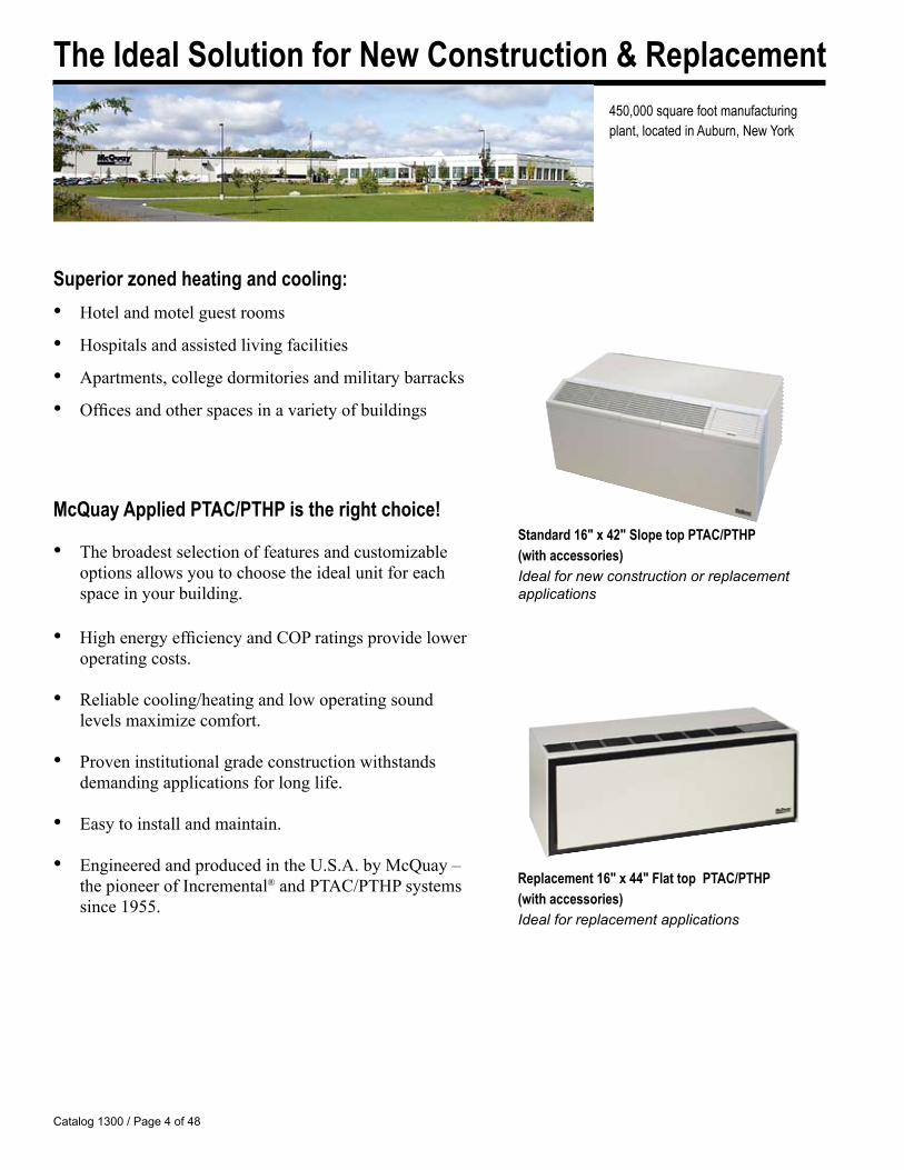
450,000 square foot manufacturing plant, located in Auburn, New York
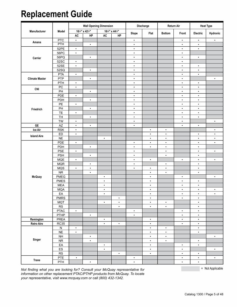
Standard 16" x 42" Slope top PTAC/PTHP (with accessories)Ideal for new construction or replacement applications
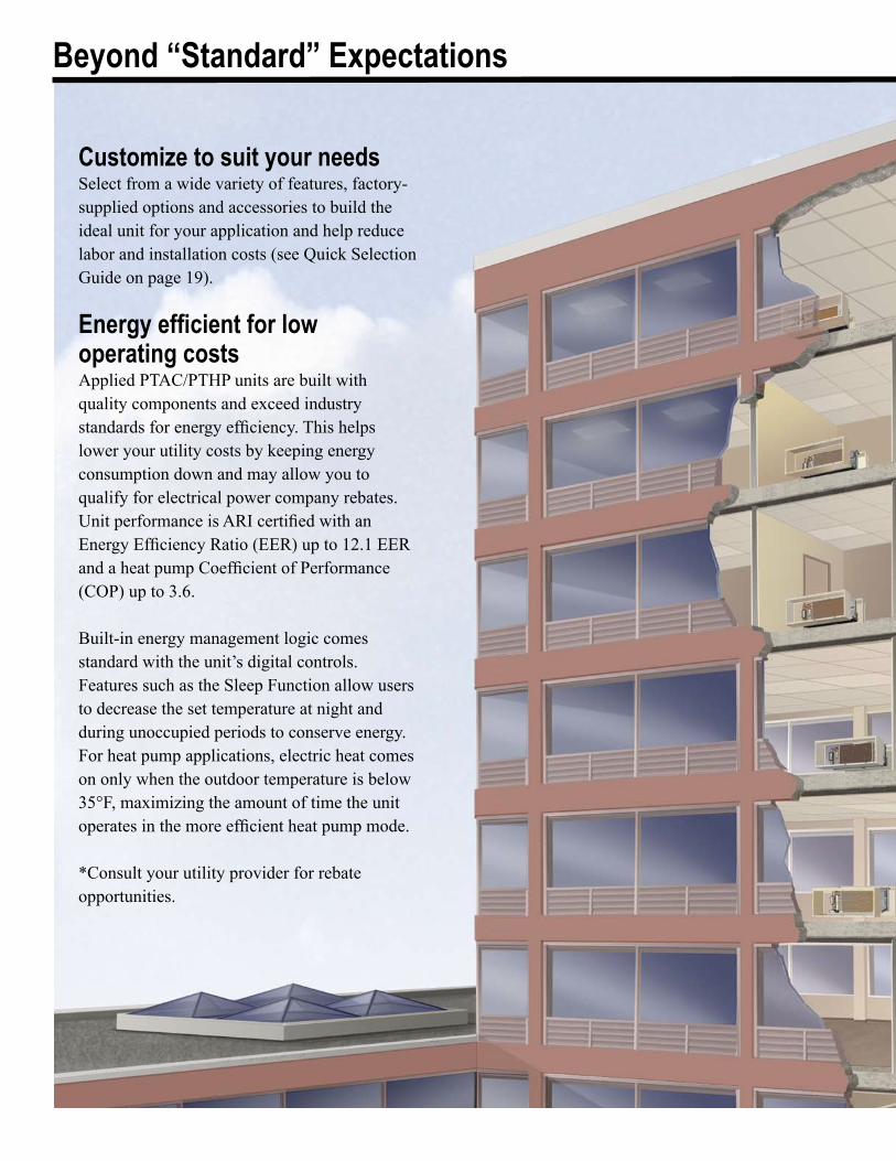
Replacement 16" x 44" Flat top PTAC/PTHP (with accessories)Ideal for replacement applications
Catalog 1300 / Page � of 48
Replacement Guide
Not finding what you are looking for? Consult your McQuay representative for information on other replacement PTAC/PTHP products from McQuay. To locate your representative, visit www.mcquay.com or call (800) 432-1342.
= Not Applicable
Wall Opening Dimension Discharge Return Air Heat Type Manufacturer Model 161/4" x 421/4" 163/8" x 447/8" AC HP AC HP
Slope Flat Bottom Front Electric Hydronic
Amana PTC • • • • • PTH • • • • �2PE • • • • �6PC • • • Carrier �6PQ • • • • �2SC • • • �2SE • • • • �2SQ • • • • PTA • • • • Climate Master PTP • • • • PTH • • • • CNI PC • • • • PH • • • • PDE • • • • PDH • • • • PE • • • • Friedrich PH • • • • TE • • • • TH • • • • TW • • • • GE AZ • • • • • Ice Air RSK • • • • Island Aire ED • • • • • NE • • • • • PDE • • • • • • PDH • • • • • PSE • • • • • PSH • • • • MQE • • • • • • MQR • • • • MQS • • • • • • NR • • • • McQuay PMEG • • • • PMES • • • • MEA • • • • MQA • • • • • EA • • • • • PMRS • • • • MQT • • • • • RS • • • • PTAC • • • • PTHP • • • • Remington PREA • • • • Retro Aire RC3� • • • • • N • • • • NE • • • • NH • • • • Singer NR • • • • EA • • • • ES • • • • RS • • • •
Trane PTE • • • • •
PTH • • • •
Customize to suit your needsSelect from a wide variety of features, factory-supplied options and accessories to build the ideal unit for your application and help reduce labor and installation costs (see Quick Selection Guide on page 19).
Energy efficient for low operating costs Applied PTAC/PTHP units are built with quality components and exceed industry standards for energy efficiency. This helps lower your utility costs by keeping energy consumption down and may allow you to qualify for electrical power company rebates. Unit performance is ARI certified with an Energy Efficiency Ratio (EER) up to 12.1 EER and a heat pump Coefficient of Performance (COP) up to 3.6.
Built-in energy management logic comes standard with the unit’s digital controls. Features such as the Sleep Function allow users to decrease the set temperature at night and during unoccupied periods to conserve energy. For heat pump applications, electric heat comes on only when the outdoor temperature is below 35°F, maximizing the amount of time the unit operates in the more efficient heat pump mode.
*Consult your utility provider for rebate opportunities.
Beyond “Standard” Expectations
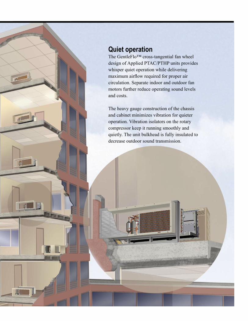
Quiet operationThe GentleFlo™ cross-tangential fan wheel design of Applied PTAC/PTHP units provides whisper quiet operation while delivering maximum airflow required for proper air circulation. Separate indoor and outdoor fan motors further reduce operating sound levels and costs.
The heavy gauge construction of the chassis and cabinet minimizes vibration for quieter operation. Vibration isolators on the rotary compressor keep it running smoothly and quietly. The unit bulkhead is fully insulated to decrease outdoor sound transmission.
Catalog 1300 / Page 8 of 48
Beyond “Standard” Expectations
Positive condensate removal
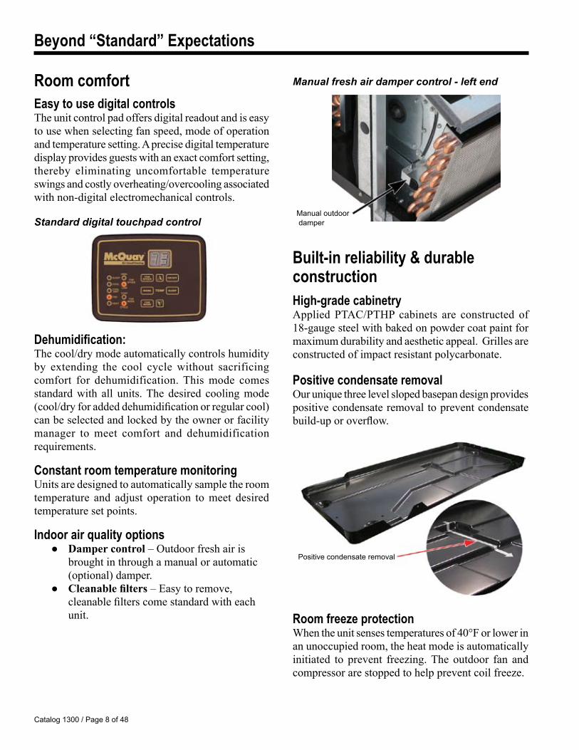
Manual fresh air damper control - left end
Built-in reliability & durable constructionHigh-grade cabinetryApplied PTAC/PTHP cabinets are constructed of 18-gauge steel with baked on powder coat paint for maximum durability and aesthetic appeal. Grilles are constructed of impact resistant polycarbonate.
Positive condensate removalOur unique three level sloped basepan design provides positive condensate removal to prevent condensate build-up or overflow.
Room freeze protectionWhen the unit senses temperatures of 40°F or lower in an unoccupied room, the heat mode is automatically initiated to prevent freezing. The outdoor fan and compressor are stopped to help prevent coil freeze.
Room comfortEasy to use digital controlsThe unit control pad offers digital readout and is easy to use when selecting fan speed, mode of operation and temperature setting. A precise digital temperature display provides guests with an exact comfort setting, thereby eliminating uncomfortable temperature swings and costly overheating/overcooling associated with non-digital electromechanical controls.
Standard digital touchpad control
Dehumidification:The cool/dry mode automatically controls humidity by extending the cool cycle without sacrificing comfort for dehumidification. This mode comes standard with all units. The desired cooling mode (cool/dry for added dehumidification or regular cool) can be selected and locked by the owner or facility manager to meet comfort and dehumidification requirements.
Constant room temperature monitoringUnits are designed to automatically sample the room temperature and adjust operation to meet desired temperature set points.
Indoor air quality options ● Damper control – Outdoor fresh air is
brought in through a manual or automatic (optional) damper.
● Cleanable filters – Easy to remove, cleanable filters come standard with each unit.
Manual outdoor damper
Catalog 1300 / Page � of 48
Beyond “Standard” Expectations
Easy to read LED diagnosticsSensors in the unit continually monitor the indoor coil, outdoor coil, and outdoor air conditions. If abnormal conditions are detected, an error code is displayed, removing the guess work in troubleshooting a unit.
The hydronic expertsMcQuay is a leading manufacturer of hydronic heat equipment. We specialize in providing hydronic heat with a host of configurable options.
Modes ● Cooling only mode with hydronic heat ● Cooling only mode with hydronic heat and supplemental electric heat. ● Top mounted hydronic coil (steam or hot water) ● Subbase hydronic (steam or hot water)
Controls-with built in hydronic logic ● Normally open/normally closed valve
control ● Heat fan lockout – prevent the fan from
coming on until there is heat in the pipes.
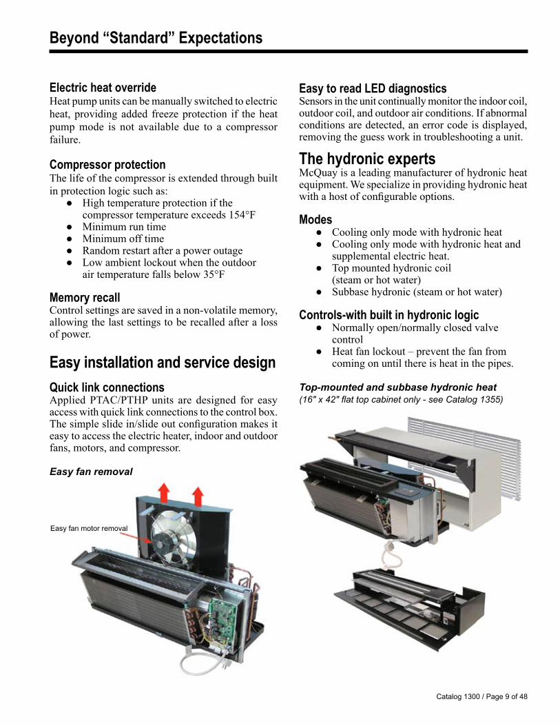
Top-mounted and subbase hydronic heat(16" x 42" flat top cabinet only - see Catalog 1355)
Easy fan motor removal
Electric heat overrideHeat pump units can be manually switched to electric heat, providing added freeze protection if the heat pump mode is not available due to a compressor failure.
Compressor protectionThe life of the compressor is extended through built in protection logic such as: ● High temperature protection if the
compressor temperature exceeds 154°F ● Minimum run time ● Minimum off time ● Random restart after a power outage ● Low ambient lockout when the outdoor
air temperature falls below 35°F
Memory recallControl settings are saved in a non-volatile memory, allowing the last settings to be recalled after a loss of power.
Easy installation and service designQuick link connectionsApplied PTAC/PTHP units are designed for easy access with quick link connections to the control box. The simple slide in/slide out configuration makes it easy to access the electric heater, indoor and outdoor fans, motors, and compressor.
Easy fan removal
Catalog 1300 / Page 10 of 48
16" x 42" Unit Features
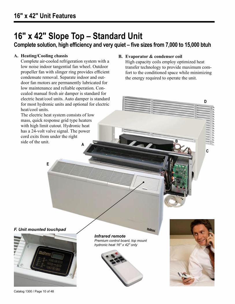
16" x 42" Slope Top – Standard UnitComplete solution, high efficiency and very quiet – five sizes from 7,000 to 15,000 btuhA. Heating/Cooling chassis Complete air-cooled refrigeration system with a
low noise indoor tangential fan wheel. Outdoor propeller fan with slinger ring provides efficient condensate removal. Separate indoor and out-door fan motors are permanently lubricated for low maintenance and reliable operation. Con-cealed manual fresh air damper is standard for electric heat/cool units. Auto damper is standard for most hydronic units and optional for electric heat/cool units.
The electric heat system consists of low mass, quick response grid type heaters with high limit cutout. Hydronic heat has a 24-volt valve signal. The power cord exits from under the right side of the unit.
B. Evaporator & condenser coil High capacity coils employ optimized heat
transfer technology to provide maximum com-fort to the conditioned space while minimizing the energy required to operate the unit.
E
AB
C
D
F. Unit mounted touchpadInfrared remote Premium control board, top mount hydronic heat 16" x 42" only
Catalog 1300 / Page 11 of 48
16" x 42" Unit Features
D. Louver (accessory) Flush stamped or architectural style. Constructed of anodized aluminum.
E. Room cabinet Sloped top discharge with sectional, two-
position raised discharge grilles. Cabinet is constructed of 18-gauge steel with baked on powder coat paint. The grilles and cabinet side panels are a high impact ABS with 94HB flame class rating. The entire room cabinet is an at-tractive antique ivory color. The control access door is on the right side of the cabinet.
F. Digital control module The Applied PTAC/PTHP digital module is
used to control the cooling and heat mode(s) of the unit and to provide diagnostic information for troubleshooting. The standard digital con-trol module is operated using a unit mounted touchpad or a 24-volt wall mounted thermostat. An optional Premium control board is infra-red (IR) capable, allowing remote control operation (Available on top mount hydronic models only).
C. Basic Wall Sleeve (BWS) 16" high x 42" wide x 13.75" deep and con-
structed from galvanized 18-gauge steel that is primed and pre-painted with an antique ivory finish. It is insulated and arrives in a removable protective plastic film.
Custom Wall Sleeve (CWS) (optional) is constructed of G-60 galvanized, phosphatized 18-gauge steel with a baked-on epoxy based powder coat paint finish to provide maximum corrosion protection. The top interior and side interior surfaces are insulated. Can be custom-ized for extended depths, recessed louvers and wall flanges.
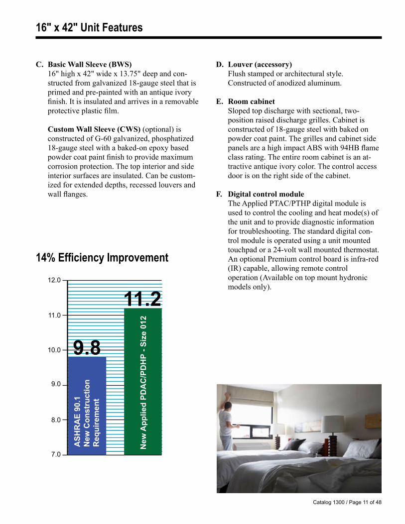
12.0
11.0
10.0
9.0
8.0
7.0
ASH
RA
E 90
.1
New
Con
stru
ctio
n R
equi
rem
ent
11.2
New
App
lied
PDA
C/P
DH
P - S
ize
012
9.8
14% Efficiency Improvement
Catalog 1300 / Page 12 of 48
16" x 44" Unit Features
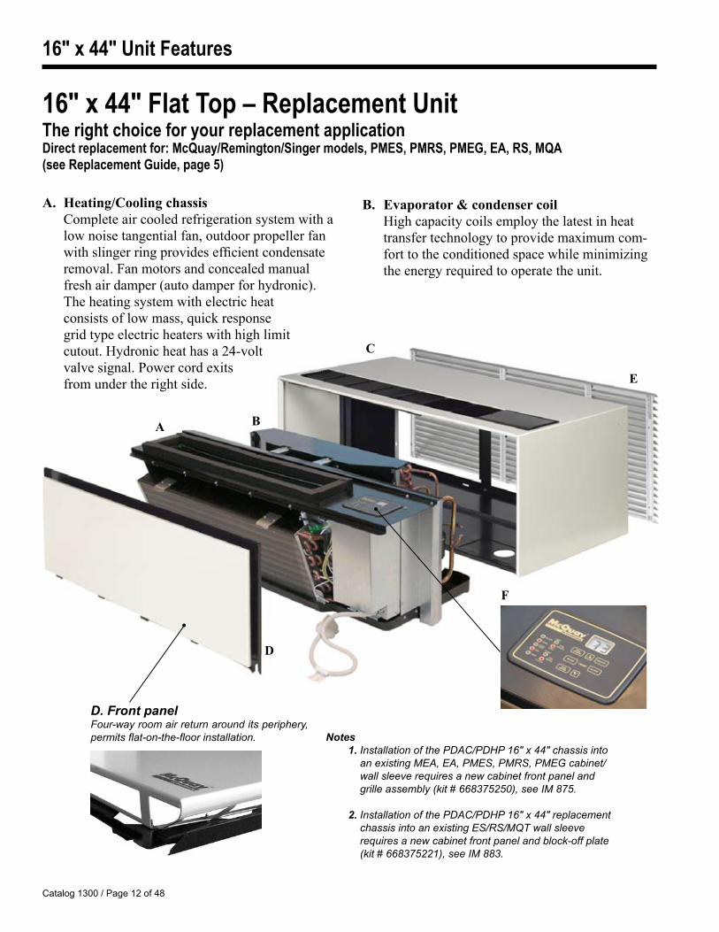
16" x 44" Flat Top – Replacement UnitThe right choice for your replacement applicationDirect replacement for: McQuay/Remington/Singer models, PMES, PMRS, PMEG, EA, RS, MQA(see Replacement Guide, page 5)
A. Heating/Cooling chassis Complete air cooled refrigeration system with a
low noise tangential fan, outdoor propeller fan with slinger ring provides efficient condensate removal. Fan motors and concealed manual fresh air damper (auto damper for hydronic). The heating system with electric heat
consists of low mass, quick response grid type electric heaters with high limit cutout. Hydronic heat has a 24-volt valve signal. Power cord exits
from under the right side.
B. Evaporator & condenser coil High capacity coils employ the latest in heat
transfer technology to provide maximum com-fort to the conditioned space while minimizing the energy required to operate the unit.
A B
C
D
D. Front panelFour-way room air return around its periphery, permits flat-on-the-floor installation.
E
F
Notes 1. Installation of the PDAC/PDHP 16" x 44" chassis into an existing MEA, EA, PMES, PMRS, PMEG cabinet/ wall sleeve requires a new cabinet front panel and grille assembly (kit # 668375250), see IM 875.
2. Installation of the PDAC/PDHP 16" x 44" replacement chassis into an existing ES/RS/MQT wall sleeve requires a new cabinet front panel and block-off plate (kit # 668375221), see IM 883.
Catalog 1300 / Page 13 of 48
16" x 44" Unit Features
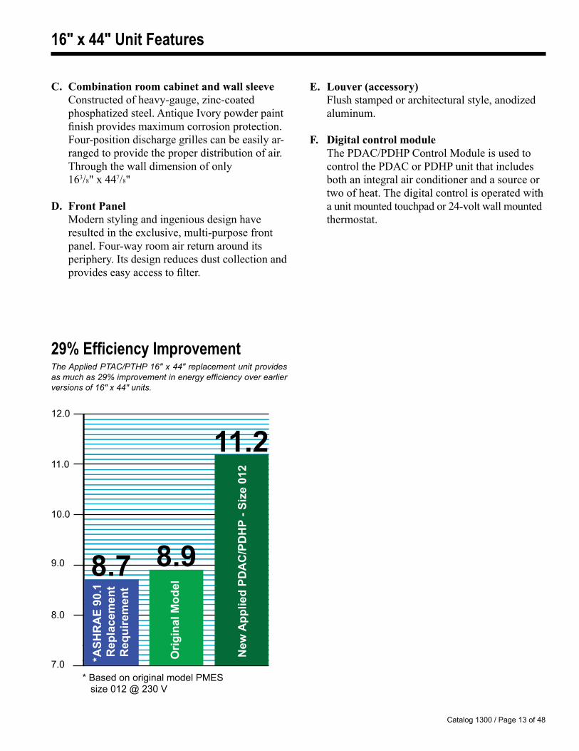
E. Louver (accessory) Flush stamped or architectural style, anodized
aluminum.
F. Digital control module The PDAC/PDHP Control Module is used to
control the PDAC or PDHP unit that includes both an integral air conditioner and a source or two of heat. The digital control is operated with a unit mounted touchpad or 24-volt wall mounted thermostat.
C. Combination room cabinet and wall sleeve Constructed of heavy-gauge, zinc-coated
phosphatized steel. Antique Ivory powder paint finish provides maximum corrosion protection. Four-position discharge grilles can be easily ar-ranged to provide the proper distribution of air. Through the wall dimension of only
163/8" x 447/8"
D. Front Panel Modern styling and ingenious design have
resulted in the exclusive, multi-purpose front panel. Four-way room air return around its periphery. Its design reduces dust collection and provides easy access to filter.
12.0
11.0
10.0
9.0
8.0
7.0 * ASH
RA
E 90
.1
Rep
lace
men
t R
equi
rem
ent
Orig
inal
Mod
el
8.9
* Based on original model PMES size 012 @ 230 V
8.7
New
App
lied
PDA
C/P
DH
P - S
ize
012
11.2
29% Efficiency ImprovementThe Applied PTAC/PTHP 16" x 44" replacement unit provides as much as 29% improvement in energy efficiency over earlier versions of 16" x 44" units.
Catalog 1300 / Page 14 of 48
Applied Chassis Common Features
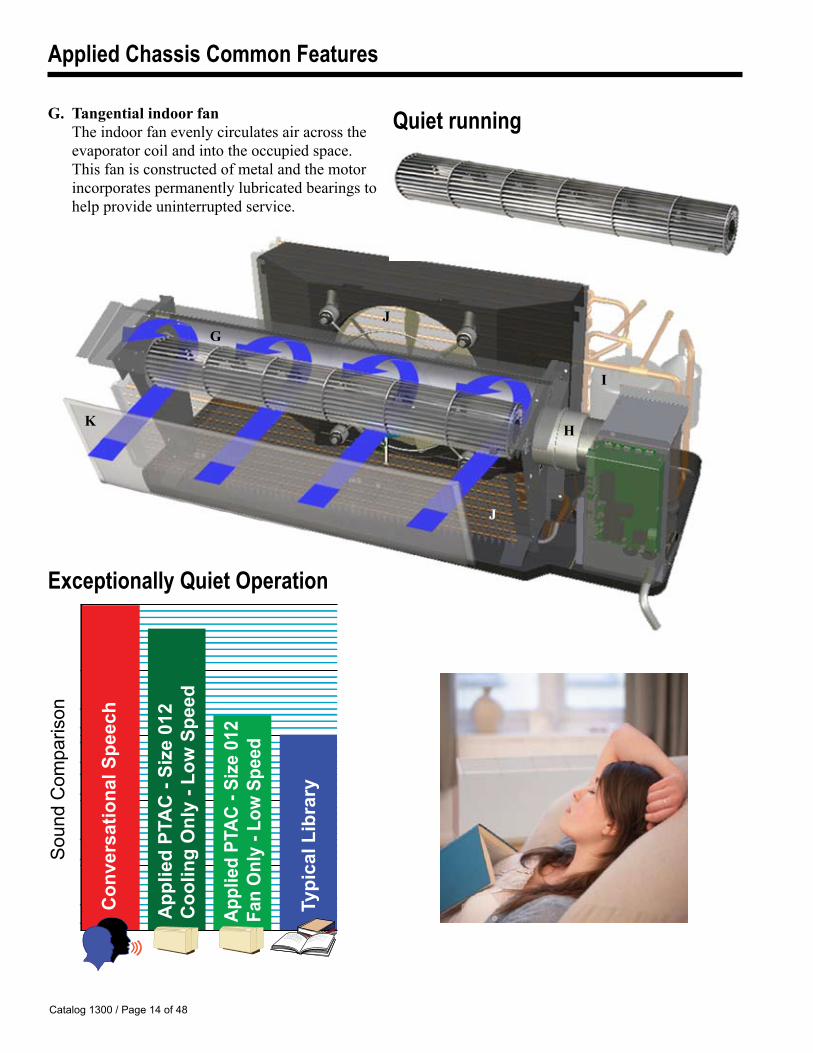
G. Tangential indoor fan The indoor fan evenly circulates air across the
evaporator coil and into the occupied space. This fan is constructed of metal and the motor incorporates permanently lubricated bearings to help provide uninterrupted service.
G
J
I
HK
J
Quiet running
Exceptionally Quiet Operation
Sou
nd C
ompa
rison
Typi
cal L
ibra
ry
App
lied
PTA
C -
Size
012
C
oolin
g O
nly
- Low
Spe
ed
Appl
ied
PTAC
- Si
ze 0
12
Fan
Onl
y - L
ow S
peed
Con
vers
atio
nal S
peec
h
Catalog 1300 / Page 1� of 48
Applied Chassis Common Features
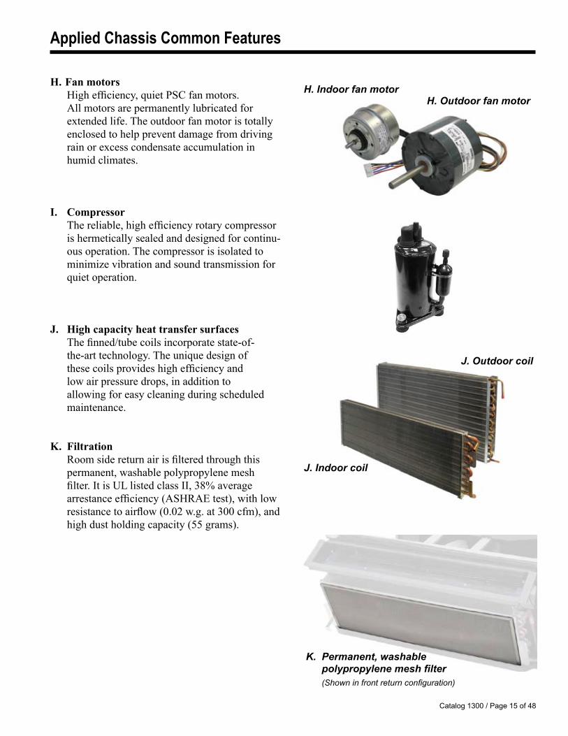
H. Indoor fan motor H. Fan motors High efficiency, quiet PSC fan motors. All motors are permanently lubricated for extended life. The outdoor fan motor is totally enclosed to help prevent damage from driving rain or excess condensate accumulation in humid climates.
I. Compressor The reliable, high efficiency rotary compressor
is hermetically sealed and designed for continu-ous operation. The compressor is isolated to minimize vibration and sound transmission for quiet operation.
J. High capacity heat transfer surfaces The finned/tube coils incorporate state-of- the-art technology. The unique design of these coils provides high efficiency and low air pressure drops, in addition to allowing for easy cleaning during scheduled maintenance.
K. Filtration Room side return air is filtered through this permanent, washable polypropylene mesh filter. It is UL listed class II, 38% average arrestance efficiency (ASHRAE test), with low resistance to airflow (0.02 w.g. at 300 cfm), and high dust holding capacity (55 grams).
J. Outdoor coil
J. Indoor coil
K. Permanent, washable polypropylenemeshfilter (Shown in front return configuration)
H. Outdoor fan motor
Catalog 1300 / Page 16 of 48
Applied Chassis Common Features
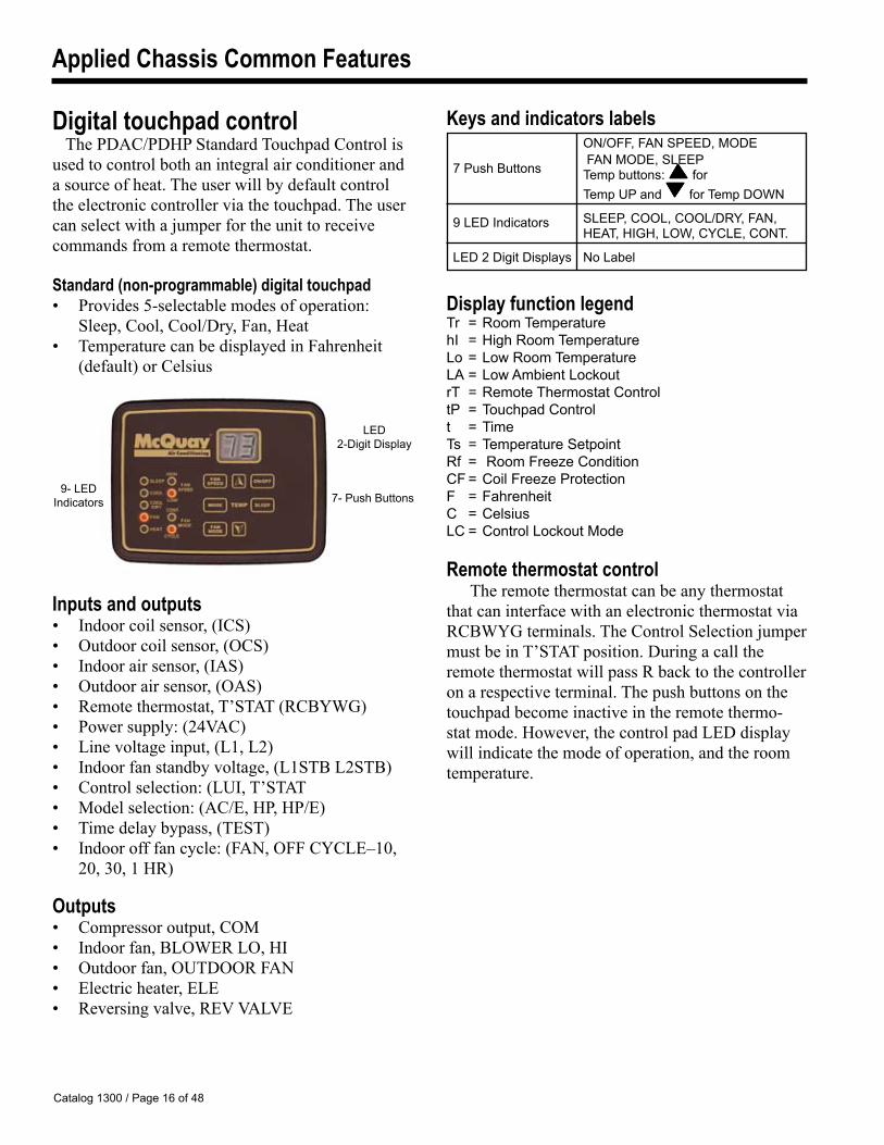
Digital touchpad controlThe PDAC/PDHP Standard Touchpad Control is
used to control both an integral air conditioner and a source of heat. The user will by default control the electronic controller via the touchpad. The user can select with a jumper for the unit to receive commands from a remote thermostat.
Standard (non-programmable) digital touchpad• Provides 5-selectable modes of operation: Sleep, Cool, Cool/Dry, Fan, Heat• Temperature can be displayed in Fahrenheit
(default) or Celsius
Inputs and outputs • Indoor coil sensor, (ICS)• Outdoor coil sensor, (OCS)• Indoor air sensor, (IAS)• Outdoor air sensor, (OAS)• Remote thermostat, T’STAT (RCBYWG)• Power supply: (24VAC) • Line voltage input, (L1, L2)• Indoor fan standby voltage, (L1STB L2STB)• Control selection: (LUI, T’STAT • Model selection: (AC/E, HP, HP/E)• Time delay bypass, (TEST) • Indoor off fan cycle: (FAN, OFF CYCLE–10, 20, 30, 1 HR)
Outputs • Compressor output, COM• Indoor fan, BLOWER LO, HI• Outdoor fan, OUTDOOR FAN• Electric heater, ELE• Reversing valve, REV VALVE
Keys and indicators labels ON/OFF, FAN SPEED, MODE
7 Push Buttons FAN MODE, SLEEP
Temp buttons: for
Temp UP and for Temp DOWN
� LED Indicators SLEEP, COOL, COOL/DRY, FAN, HEAT, HIGH, LOW, CYCLE, CONT.
LED 2 Digit Displays No Label
Display function legendTr = Room TemperaturehI = High Room TemperatureLo = Low Room TemperatureLA = Low Ambient LockoutrT = Remote Thermostat ControltP = Touchpad Controlt = TimeTs = Temperature Setpoint Rf = Room Freeze ConditionCF = Coil Freeze ProtectionF = FahrenheitC = CelsiusLC = Control Lockout Mode
Remote thermostat control The remote thermostat can be any thermostat
that can interface with an electronic thermostat via RCBWYG terminals. The Control Selection jumper must be in T’STAT position. During a call the remote thermostat will pass R back to the controller on a respective terminal. The push buttons on the touchpad become inactive in the remote thermo-stat mode. However, the control pad LED display will indicate the mode of operation, and the room temperature.
�- LED Indicators
LED 2-Digit Display
7- Push Buttons
Catalog 1300 / Page 17 of 48
Applied Chassis Common Features
Display inputs:
ON/OFF Turn the unit on and off
Increase the temperature set point
Decrease the temperature set point
MODE Select one from the following modes: COOL, COOL/DRY, FAN, or HEAT
FAN MODE Change the mode of fan operation between CYCLE and CONTINUOUS
FAN SPEED Change the speed of the fan between HIGH and LOW
SLEEP Activate the sleep mode and set the sleep time
PROG ON/OFF Button to activate and deactivate the program mode
LED with Program Setting Display
8- Push Button Display Inputs
�-LED Indicators
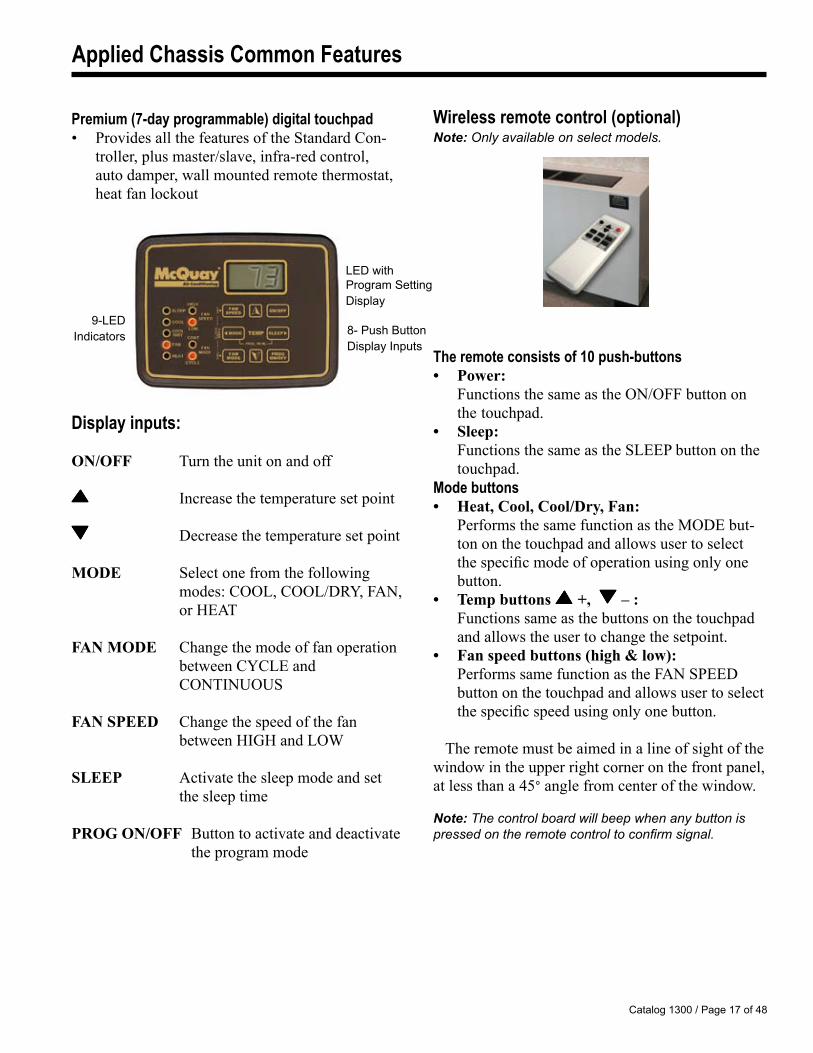
Premium (7-day programmable) digital touchpad• Provides all the features of the Standard Con-
troller, plus master/slave, infra-red control, auto damper, wall mounted remote thermostat, heat fan lockout
Wireless remote control (optional)Note: Only available on select models.
The remote consists of 10 push-buttons• Power: Functions the same as the ON/OFF button on the touchpad.• Sleep: Functions the same as the SLEEP button on the touchpad. Mode buttons• Heat, Cool, Cool/Dry, Fan: Performs the same function as the MODE but-
ton on the touchpad and allows user to select the specific mode of operation using only one button.
• Temp buttons +, – : Functions same as the buttons on the touchpad
and allows the user to change the setpoint. • Fan speed buttons (high & low): Performs same function as the FAN SPEED
button on the touchpad and allows user to select the specific speed using only one button.
The remote must be aimed in a line of sight of the window in the upper right corner on the front panel, at less than a 45° angle from center of the window.
Note: The control board will beep when any button is pressed on the remote control to confirm signal.
Catalog 1300 / Page 18 of 48
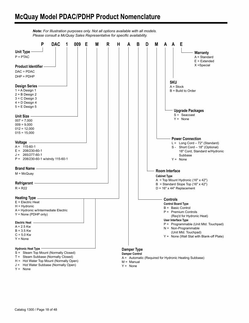
McQuay Model PDAC/PDHP Product Nomenclature
Note: For Illustration purposes only. Not all options available with all models. Please consult a McQuay Sales Representative for specific availability.
Damper TypeDamper ControlA = Automatic (Required for Hydronic Heating Subbase)M = ManualY = None
Unit TypeP = PTAC
Product IdentifierDAC = PDACDHP = PDHP
Design Series1 = A Design 12 = B Design 23 = C Design 34 = D Design 4� = E Design �
Unit Size007 = 7,00000� = �,000012 = 12,00001� = 1�,000
VoltageA = 11�-60-1E = 208/230-60-1J = 26�/277-60-1P = 208/230-60-1 w/stndy 11�-60-1
Brand NameM = McQuay
RefrigerantR = R22
Heating TypeE = Electric HeatH = HydronicA = Hydronic w/Intermediate ElectricY = None (PDHP only)
Electric HeatA = 2.� KwB = 3.� KwC = �.0 KwY = None
Hydronic Heat TypeS = Steam Top Mount (Normally Closed)T = Steam Subbase (Normally Closed)H = Hot Water Top Mount (Normally Open)J = Hot Water Subbase (Normally Open)Y = None
SKUA = StockB = Build to Order
P DAC 1 009 E M R H A B D M A A E
ControlsControl Board TypeB = Basic ControlP = Premium Controls (Req'd for Hydronic Heat)User Interface TypeP = Programmable (Unit Mtd. Touchpad)N = Non-Programmable (Unit Mtd. Touchpad)Y = None (Wall Stat with Blank-off Plate)
Room InterfaceCabinet TypeA = Top Mount Hydronic (16" x 42")B = Standard Slope Top (16" x 42")D = 16" x 44" Replacement
Power ConnectionL = Long Cord – 72" (Standard)S - Short Cord – 18" (Optional)
18" Cord, Standard w/Hydronic Subbase
Y = None
Upgrade PackagesS = SeacoastY = None
WarrantyA = StandardE = ExtendedX =Special
Catalog 1300 / Page 1� of 48
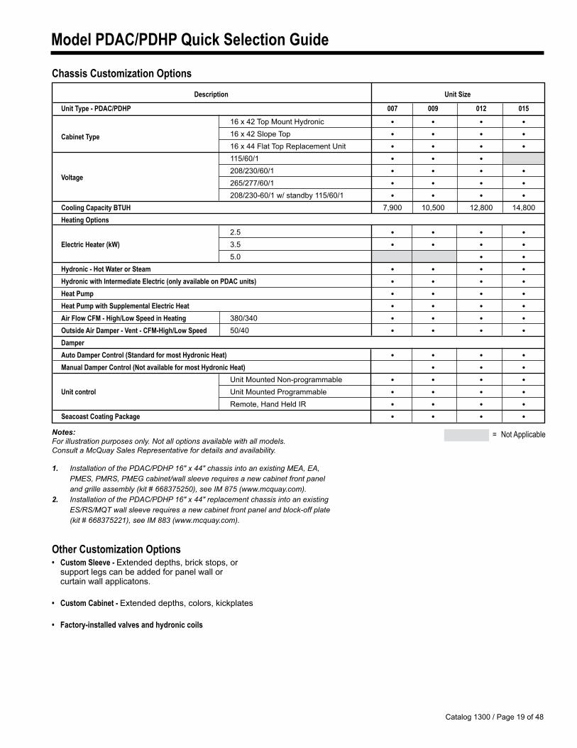
Model PDAC/PDHP Quick Selection Guide
Chassis Customization Options
Notes: For illustration purposes only. Not all options available with all models. Consult a McQuay Sales Representative for details and availability.
1. Installation of the PDAC/PDHP 16" x 44" chassis into an existing MEA, EA, PMES, PMRS, PMEG cabinet/wall sleeve requires a new cabinet front panel and grille assembly (kit # 668375250), see IM 875 (www.mcquay.com).2. Installation of the PDAC/PDHP 16" x 44" replacement chassis into an existing ES/RS/MQT wall sleeve requires a new cabinet front panel and block-off plate (kit # 668375221), see IM 883 (www.mcquay.com).
Other Customization Options• Custom Sleeve - Extended depths, brick stops, or support legs can be added for panel wall or curtain wall applicatons.
• Custom Cabinet - Extended depths, colors, kickplates
• Factory-installed valves and hydronic coils
= Not Applicable
Description Unit Size
Unit Type - PDAC/PDHP 007 009 012 015 16 x 42 Top Mount Hydronic • • • • Cabinet Type 16 x 42 Slope Top • • • • 16 x 44 Flat Top Replacement Unit • • • • 11�/60/1 • • • 208/230/60/1 • • • •
Voltage 26�/277/60/1 • • • •
208/230-60/1 w/ standby 11�/60/1 • • • • Cooling Capacity BTUH 7,�00 10,�00 12,800 14,800 Heating Options 2.� • • • • Electric Heater (kW) 3.� • • • • �.0 • • Hydronic - Hot Water or Steam • • • • Hydronic with Intermediate Electric (only available on PDAC units) • • • • Heat Pump • • • • Heat Pump with Supplemental Electric Heat • • • • Air Flow CFM - High/Low Speed in Heating 380/340 • • • • Outside Air Damper - Vent - CFM-High/Low Speed �0/40 • • • • Damper Auto Damper Control (Standard for most Hydronic Heat) • • • • Manual Damper Control (Not available for most Hydronic Heat) • • • Unit Mounted Non-programmable • • • • Unit control Unit Mounted Programmable • • • • Remote, Hand Held IR • • • • Seacoast Coating Package • • • •
Catalog 1300 / Page 20 of 48
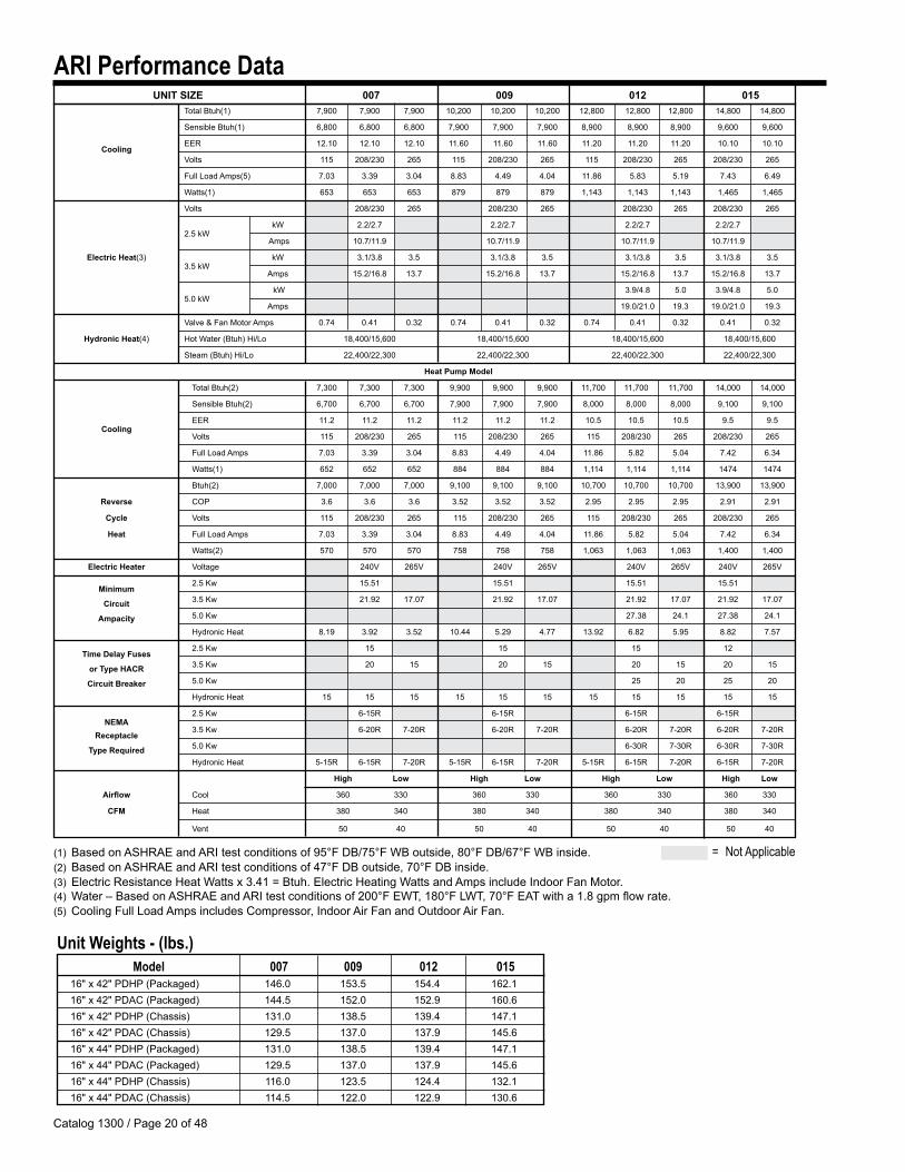
Total Btuh(1) 7,�00 7,�00 7,�00 10,200 10,200 10,200 12,800 12,800 12,800 14,800 14,800
Sensible Btuh(1) 6,800 6,800 6,800 7,�00 7,�00 7,�00 8,�00 8,�00 8,�00 �,600 �,600
Cooling
EER 12.10 12.10 12.10 11.60 11.60 11.60 11.20 11.20 11.20 10.10 10.10
Volts 11� 208/230 26� 11� 208/230 26� 11� 208/230 26� 208/230 26�
Full Load Amps(�) 7.03 3.3� 3.04 8.83 4.4� 4.04 11.86 �.83 �.1� 7.43 6.4�
Watts(1) 6�3 6�3 6�3 87� 87� 87� 1,143 1,143 1,143 1,46� 1,46�
Volts 208/230 26� 208/230 26� 208/230 26� 208/230 26�
kW 2.2/2.7 2.2/2.7 2.2/2.7 2.2/2.7
2.� kW
Amps 10.7/11.� 10.7/11.� 10.7/11.� 10.7/11.�
ElectricHeat(3) kW 3.1/3.8 3.� 3.1/3.8 3.� 3.1/3.8 3.� 3.1/3.8 3.�
3.� kW
Amps 1�.2/16.8 13.7 1�.2/16.8 13.7 1�.2/16.8 13.7 1�.2/16.8 13.7
�.0 kW
kW 3.�/4.8 �.0 3.�/4.8 �.0
Amps 1�.0/21.0 1�.3 1�.0/21.0 1�.3
Valve & Fan Motor Amps 0.74 0.41 0.32 0.74 0.41 0.32 0.74 0.41 0.32 0.41 0.32
HydronicHeat(4) Hot Water (Btuh) Hi/Lo 18,400/1�,600 18,400/1�,600 18,400/1�,600 18,400/1�,600
Steam (Btuh) Hi/Lo 22,400/22,300 22,400/22,300 22,400/22,300 22,400/22,300 HeatPumpModel
Total Btuh(2) 7,300 7,300 7,300 �,�00 �,�00 �,�00 11,700 11,700 11,700 14,000 14,000
Sensible Btuh(2) 6,700 6,700 6,700 7,�00 7,�00 7,�00 8,000 8,000 8,000 �,100 �,100
EER 11.2 11.2 11.2 11.2 11.2 11.2 10.� 10.� 10.� �.� �.�
Cooling
Volts 11� 208/230 26� 11� 208/230 26� 11� 208/230 26� 208/230 26�
Full Load Amps 7.03 3.3� 3.04 8.83 4.4� 4.04 11.86 �.82 �.04 7.42 6.34
Watts(1) 6�2 6�2 6�2 884 884 884 1,114 1,114 1,114 1474 1474
Btuh(2) 7,000 7,000 7,000 �,100 �,100 �,100 10,700 10,700 10,700 13,�00 13,�00
Reverse COP 3.6 3.6 3.6 3.�2 3.�2 3.�2 2.�� 2.�� 2.�� 2.�1 2.�1
Cycle Volts 11� 208/230 26� 11� 208/230 26� 11� 208/230 26� 208/230 26�
Heat Full Load Amps 7.03 3.3� 3.04 8.83 4.4� 4.04 11.86 �.82 �.04 7.42 6.34
Watts(2) �70 �70 �70 7�8 7�8 7�8 1,063 1,063 1,063 1,400 1,400
ElectricHeater Voltage 240V 26�V 240V 26�V 240V 26�V 240V 26�V
Minimum
2.� Kw 1�.�1 1�.�1 1�.�1 1�.�1
Circuit 3.� Kw 21.�2 17.07 21.�2 17.07 21.�2 17.07 21.�2 17.07
Ampacity �.0 Kw 27.38 24.1 27.38 24.1
Hydronic Heat 8.1� 3.�2 3.�2 10.44 �.2� 4.77 13.�2 6.82 �.�� 8.82 7.�7
TimeDelayFuses
2.� Kw 1� 1� 1� 12
orTypeHACR 3.� Kw 20 1� 20 1� 20 1� 20 1�
CircuitBreaker �.0 Kw 2� 20 2� 20
Hydronic Heat 1� 1� 1� 1� 1� 1� 1� 1� 1� 1� 1�
NEMA
2.� Kw 6-1�R 6-1�R 6-1�R 6-1�R
Receptacle
3.� Kw 6-20R 7-20R 6-20R 7-20R 6-20R 7-20R 6-20R 7-20R
TypeRequired �.0 Kw 6-30R 7-30R 6-30R 7-30R
Hydronic Heat �-1�R 6-1�R 7-20R �-1�R 6-1�R 7-20R �-1�R 6-1�R 7-20R 6-1�R 7-20R
High Low High Low High Low High Low
Airflow Cool 360 330 360 330 360 330 360 330
CFM Heat 380 340 380 340 380 340 380 340
Vent �0 40 �0 40 �0 40 �0 40
UNITSIZE 007 009 012 015ARI Performance Data
(1) Based on ASHRAE and ARI test conditions of ��°F DB/7�°F WB outside, 80°F DB/67°F WB inside. (2) Based on ASHRAE and ARI test conditions of 47°F DB outside, 70°F DB inside.(3) Electric Resistance Heat Watts x 3.41 = Btuh. Electric Heating Watts and Amps include Indoor Fan Motor. (4) Water – Based on ASHRAE and ARI test conditions of 200°F EWT, 180°F LWT, 70°F EAT with a 1.8 gpm flow rate.(�) Cooling Full Load Amps includes Compressor, Indoor Air Fan and Outdoor Air Fan.
Model 007 009 012 01516" x 42" PDHP (Packaged) 146.0 1�3.� 1�4.4 162.116" x 42" PDAC (Packaged) 144.� 1�2.0 1�2.� 160.616" x 42" PDHP (Chassis) 131.0 138.� 13�.4 147.116" x 42" PDAC (Chassis) 12�.� 137.0 137.� 14�.616" x 44" PDHP (Packaged) 131.0 138.� 13�.4 147.116" x 44" PDAC (Packaged) 12�.� 137.0 137.� 14�.616" x 44" PDHP (Chassis) 116.0 123.� 124.4 132.116" x 44" PDAC (Chassis) 114.� 122.0 122.� 130.6
Unit Weights - (lbs.)
= Not Applicable
Catalog 1300 / Page 21 of 48
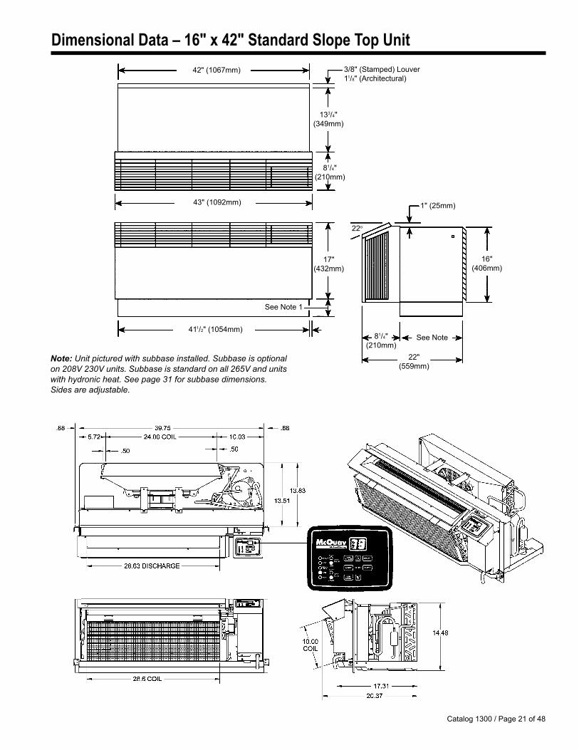
Dimensional Data – 16" x 42" Standard Slope Top Unit
133/4" (34�mm)
42" (1067mm)
43" (10�2mm)
411/2" (10�4mm)
81/4" (210mm)
3/8" (Stamped) Louver 11/8" (Architectural)
17" (432mm)
16" (406mm)
81/4" (210mm)
22" (���mm)
See Note
See Note 1
22o
1" (2�mm)
Note: Unit pictured with subbase installed. Subbase is optional on 208V 230V units. Subbase is standard on all 265V and units with hydronic heat. See page 31 for subbase dimensions. Sides are adjustable.
Catalog 1300 / Page 22 of 48
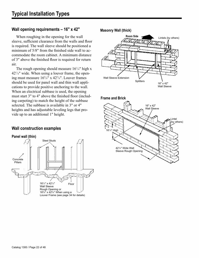
Panel wall (thin)
Frame and Brick
Masonry Wall (thick)
161/4" x 421/4" Wall Sleeve Rough Opening or 16�/8" x 42�/8" When using a Louver Frame (see page 34 for details)
Floor
Concrete Pillars
Steel Studs
16" x 42" Wall Sleeve
Lintel (by others)
421/4" Wide Wall Sleeve Rough Opening
161/4" HighWall construction examples
Wall opening requirements – 16" x 42"When roughing in the opening for the wall
sleeve, sufficient clearance from the walls and floor is required. The wall sleeve should be positioned a minimum of 5/8" from the finished side wall to ac-commodate the room cabinet. A minimum distance of 3" above the finished floor is required for return air.
The rough opening should measure 161/4" high x 421/4" wide. When using a louver frame, the open-ing must measure 165/8" x 425/8". Louver frames should be used for panel wall and thin wall appli-cations to provide positive anchoring to the wall. When an electrical subbase is used, the opening must start 3" to 4" above the finished floor (includ-ing carpeting) to match the height of the subbase selected. The subbase is available in 3" or 4" heights and has adjustable leveling legs that pro-vide up to an additional 1" height.
Wall Sleeve ExtensionSplitters
16" x 42" Wall Sleeve
Lintels (by others)Room Side
Typical Installation Types
Catalog 1300 / Page 23 of 48
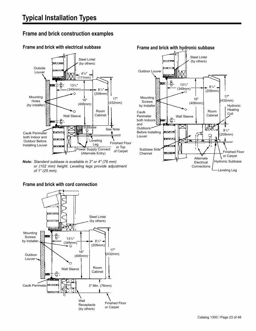
Finished Flooror Carpet
Frame and brick with electrical subbase
Note: Standard subbase is available in 3" or 4" (76 mm) or (102 mm) height. Leveling legs provide adjustment of 1" (25 mm).
Steel Lintel (by others)
43/8"(111mm)
OutsideLouver
MountingHoles
(by installer)
81/4"(20�mm)
Caulk Perimeterboth Indoor andOutdoor Before Installing Louver
Power Supply Connect(Alternate Entry)
Leveling Leg Finished Floor
or Top of Carpet
See Note
133/4"(34�mm)
Wall SleeveRoom
Cabinet
Subbase
16"(406mm)
17"(432mm)
Frame and brick with cord connection
3" Min. (76mm)
Wall Receptacle (by others)
Frame and brick with hydronic subbase
MountingScrews
by Installer
Outdoor Louver
Steel Lintel(by others)
HydronicHeating Coil
16"(406mm)
81/4"(20�mm)
133/4"(34�mm)
Caulk Perimeter both Indoors and Outdoors Before Installing Louver
Subbase Side Channel
Alternate Electrical
ConnectionsHydronic Subbase
81/4"(20�mm)
RoomCabinetWall Sleeve
17"(432mm)
Leveling Leg
Steel Lintel (by others)
16"(406mm)
81/4"(20�mm)
133/4"(34�mm)
RoomCabinet
Wall Sleeve
17"(432mm)
MountingScrews
by Installer
Outdoor Louver
Caulk Perimeter
Finished Flooror Carpet
Typical Installation Types
Frame and brick construction examples
Catalog 1300 / Page 24 of 48
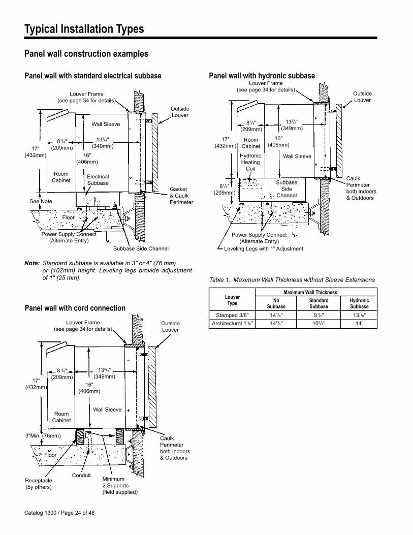
Maximum Wall Thickness Louver No Standard Hydronic Type Subbase Subbase Subbase
Stamped 3/8" 141/8" �1/2" 131/8" Architectural 11/8" 147/8" 103/8" 14"
Panel wall with cord connection
3"Min. (76mm)
Conduit
Floor
Receptacle (by others)
17"(432mm)
81/4"(20�mm)
16"(406mm)
RoomCabinet
Note: Standard subbase is available in 3" or 4" (76 mm) or (102mm) height. Leveling legs provide adjustment of 1" (25 mm).
Panel wall with standard electrical subbase
17"(432mm)
81/4"(20�mm)
16"(406mm)
Power Supply Connect(Alternate Entry)
See Note
RoomCabinet
Panel wall with hydronic subbase
Minimum 2 Supports (field supplied)
HydronicHeating
Coil
Leveling Legs with 1” Adjustment
Caulk Perimeter both Indoors & Outdoors
Outside Louver
133/4"(34�mm)
Wall Sleeve
SubbaseSide
Channel
Power Supply Connect(Alternate Entry)
Caulk Perimeter both Indoors & Outdoors
Outside Louver
81/4"(20�mm)
133/4"(34�mm)
16"(406mm)
Wall Sleeve
RoomCabinet
17"(432mm)
81/4"(20�mm)
Louver Frame(see page 34 for details)
Electrical Subbase
Subbase Side Channel
Gasket & Caulk Perimeter
Outside Louver
133/4"(34�mm)
Wall Sleeve
Floor
Louver Frame(see page 34 for details)
Louver Frame(see page 34 for details)
Typical Installation Types
Panel wall construction examples
Table 1. Maximum Wall Thickness without Sleeve Extensions
Catalog 1300 / Page 2� of 48
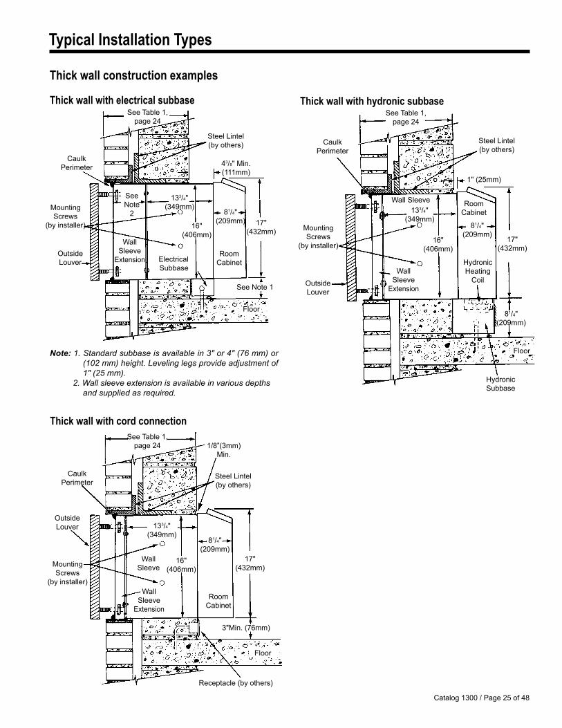
Thick wall with cord connection
1/8”(3mm)Min.
Caulk Perimeter
Mounting Screws
(by installer)Wall
SleeveExtension
Steel Lintel(by others)
Floor
16"(406mm)
133/4"(34�mm)
17"(432mm)
RoomCabinet
Outside Louver
81/4"(20�mm)
3"Min. (76mm)
Wall Sleeve
Receptacle (by others)
Thick wall with electrical subbase
Note: 1. Standard subbase is available in 3" or 4" (76 mm) or (102 mm) height. Leveling legs provide adjustment of 1" (25 mm).
2. Wall sleeve extension is available in various depths and supplied as required.
See Table 1,page 24
Caulk Perimeter
Mounting Screws
(by installer)
See Note
2
Wall Sleeve
Extension ElectricalSubbase
Steel Lintel(by others)
See Note 1
Floor
43/8" Min. (111mm)
16"(406mm)
133/4"(34�mm)
17"(432mm)
RoomCabinet
Outside Louver
81/4"(20�mm)
Thick wall with hydronic subbaseSee Table 1,
page 24
1" (2�mm)
Hydronic Subbase
Floor
HydronicHeating
Coil
81/4"(20�mm)
133/4"(34�mm)
16"(406mm)
Wall Sleeve RoomCabinet
17"(432mm)
81/4"(20�mm)
Wall Sleeve
ExtensionOutside Louver
Mounting Screws
(by installer)
Caulk Perimeter
Steel Lintel(by others)
Typical Installation Types
Thick wall construction examples
See Table 1,page 24
Catalog 1300 / Page 26 of 48
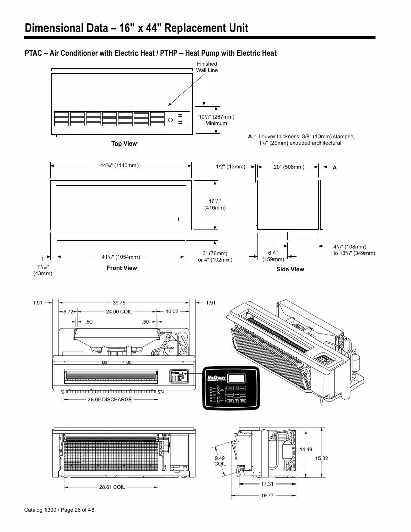
Dimensional Data – 16" x 44" Replacement Unit
PTAC – Air Conditioner with Electric Heat / PTHP – Heat Pump with Electric Heat
163/8" (416mm)
447/8" (1140mm)
411/2" (10�4mm)
111/16" (43mm)
3" (76mm)or 4" (102mm)
101/2" (267mm) Minimum
Finished Wall Line
61/4" (1��mm)
41/4" (108mm) to 133/4" (34�mm)
20" (�08mm) 1/2" (13mm) A
A = Louver thickness: 3/8" (10mm) stamped, 11/8" (2�mm) extruded architecturalTopView
FrontView SideView
Catalog 1300 / Page 27 of 48
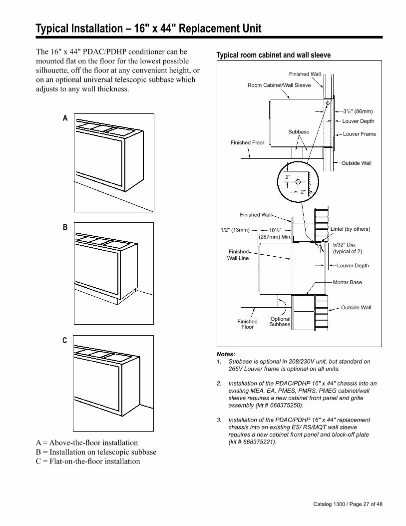
Typical Installation – 16" x 44" Replacement Unit
The 16" x 44" PDAC/PDHP conditioner can be mounted flat on the floor for the lowest possible silhouette, off the floor at any convenient height, or on an optional universal telescopic subbase which adjusts to any wall thickness.
A = Above-the-floor installationB = Installation on telescopic subbase C = Flat-on-the-floor installation
A
B
C
Typical room cabinet and wall sleeve
Finished Wall Line
Outside Wall
Louver Depth
Mortar Base
Lintel (by others)
Finished Wall
Finished Floor
OptionalSubbase
Room Cabinet/Wall Sleeve
Finished Wall
Outside Wall
2"
2"
101/2" (267mm) Min.
1/2" (13mm)
Notes: 1. Subbase is optional in 208/230V unit, but standard on 265V Louver frame is optional on all units.
2. Installation of the PDAC/PDHP 16" x 44" chassis into an existing MEA, EA, PMES, PMRS, PMEG cabinet/wall sleeve requires a new cabinet front panel and grille assembly (kit # 668375250).
3. Installation of the PDAC/PDHP 16" x 44" replacement chassis into an existing ES/ RS/MQT wall sleeve requires a new cabinet front panel and block-off plate (kit # 668375221).
33/8" (86mm)
�/32" Dia. (typical of 2)
Louver Depth
Louver FrameFinished Floor
Subbase
Catalog 1300 / Page 28 of 48
Accessories
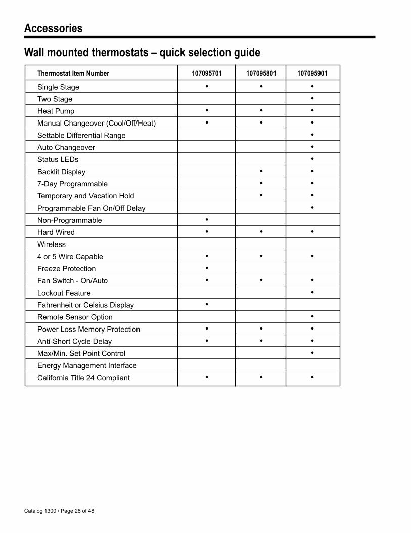
Thermostat Item Number 107095701 107095801 107095901
Single Stage • • • Two Stage • Heat Pump • • • Manual Changeover (Cool/Off/Heat) • • • Settable Differential Range • Auto Changeover • Status LEDs • Backlit Display • • 7-Day Programmable • • Temporary and Vacation Hold • • Programmable Fan On/Off Delay • Non-Programmable • Hard Wired • • • Wireless 4 or � Wire Capable • • • Freeze Protection • Fan Switch - On/Auto • • • Lockout Feature • Fahrenheit or Celsius Display • Remote Sensor Option • Power Loss Memory Protection • • • Anti-Short Cycle Delay • • • Max/Min. Set Point Control • Energy Management Interface California Title 24 Compliant • • •
Wall mounted thermostats – quick selection guide
Catalog 1300 / Page 2� of 48
Accessories
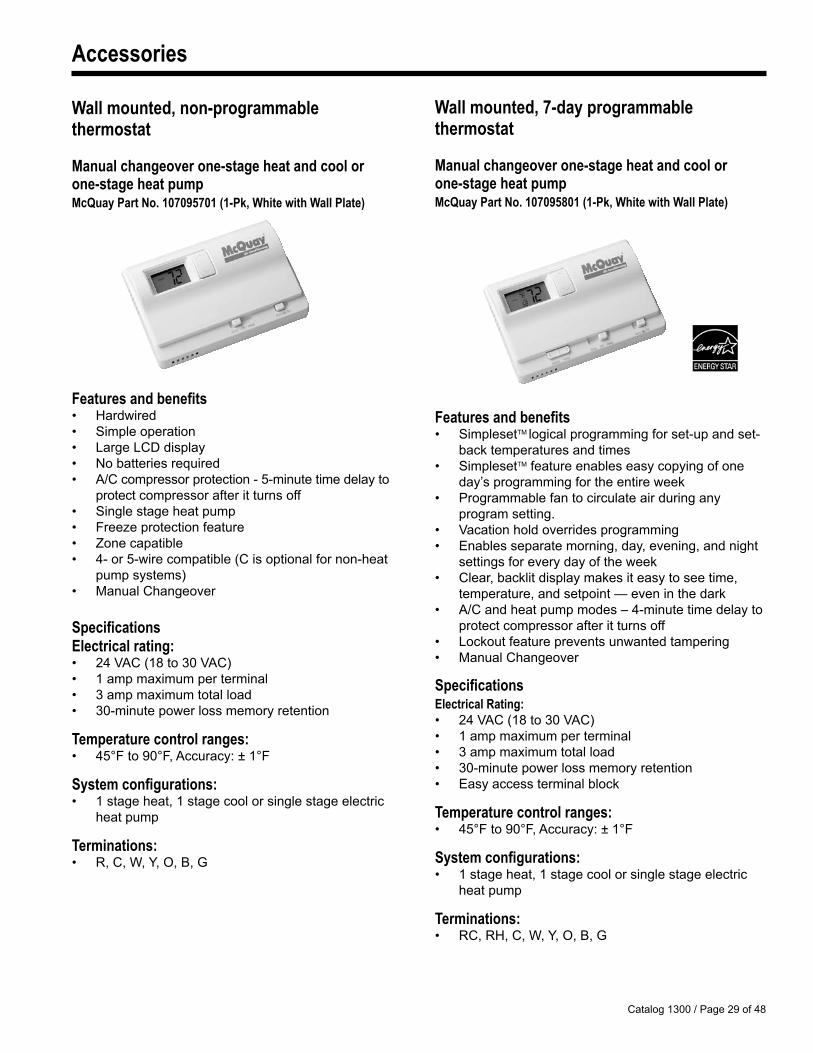
Wall mounted, non-programmable thermostat
Manual changeover one-stage heat and cool or one-stage heat pumpMcQuay Part No. 107095701 (1-Pk, White with Wall Plate)
Features and benefits• Hardwired• Simple operation• Large LCD display• No batteries required• A/C compressor protection - �-minute time delay to protect compressor after it turns off• Single stage heat pump• Freeze protection feature• Zone capatible• 4- or �-wire compatible (C is optional for non-heat pump systems)• Manual Changeover
SpecificationsElectrical rating:• 24 VAC (18 to 30 VAC)• 1 amp maximum per terminal• 3 amp maximum total load• 30-minute power loss memory retention
Temperature control ranges:• 4�°F to �0°F, Accuracy: ± 1°F
System configurations:• 1 stage heat, 1 stage cool or single stage electric heat pump
Terminations:• R, C, W, Y, O, B, G
Wall mounted, 7-day programmablethermostat
Manual changeover one-stage heat and cool or one-stage heat pumpMcQuay Part No. 107095801 (1-Pk, White with Wall Plate)
Features and benefits• SimplesetTM logical programming for set-up and set- back temperatures and times• SimplesetTM feature enables easy copying of one day’s programming for the entire week• Programmable fan to circulate air during any program setting.• Vacation hold overrides programming• Enables separate morning, day, evening, and night settings for every day of the week• Clear, backlit display makes it easy to see time, temperature, and setpoint — even in the dark• A/C and heat pump modes – 4-minute time delay to protect compressor after it turns off• Lockout feature prevents unwanted tampering• Manual Changeover
SpecificationsElectrical Rating:• 24 VAC (18 to 30 VAC)• 1 amp maximum per terminal• 3 amp maximum total load• 30-minute power loss memory retention• Easy access terminal block
Temperature control ranges:• 4�°F to �0°F, Accuracy: ± 1°F
System configurations:• 1 stage heat, 1 stage cool or single stage electric heat pump
Terminations:• RC, RH, C, W, Y, O, B, G
Catalog 1300 / Page 30 of 48
Accessories
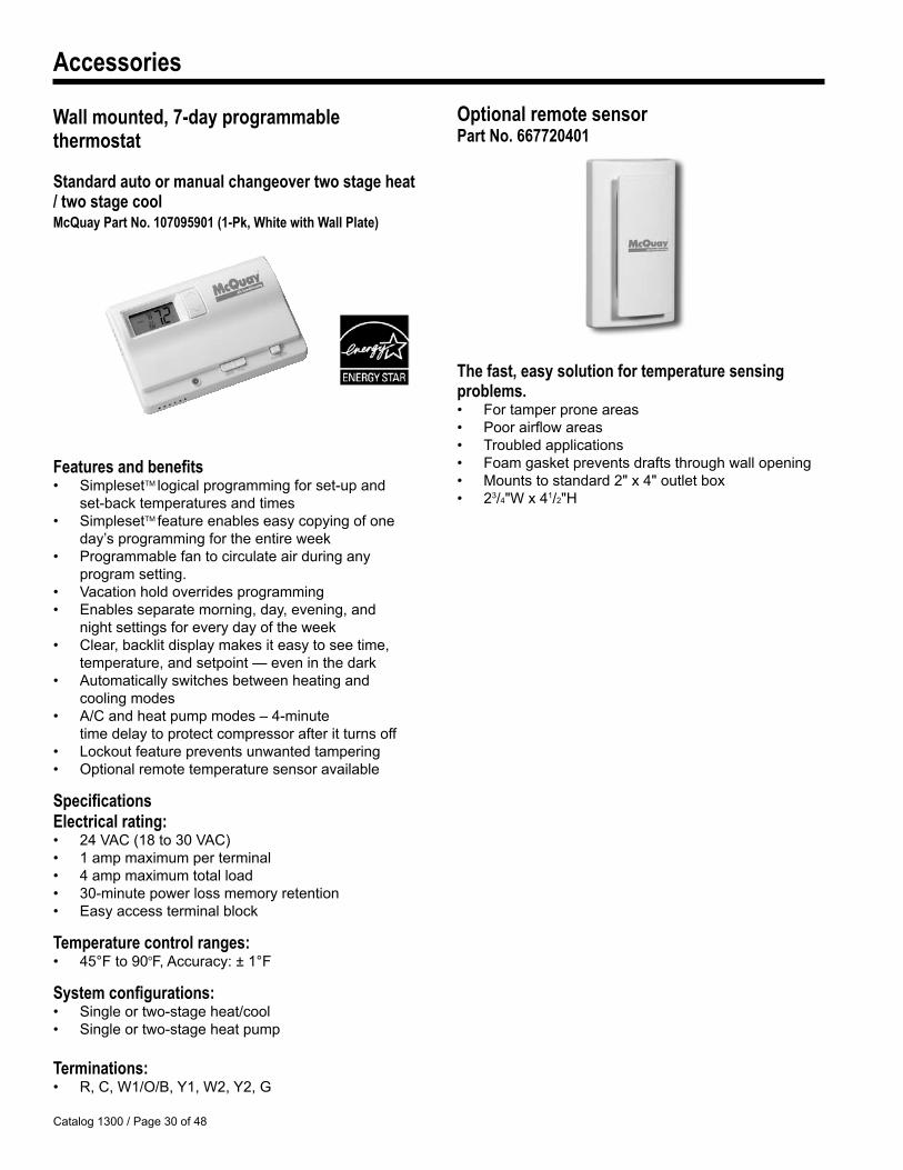
Wall mounted, 7-day programmablethermostat
Standard auto or manual changeover two stage heat / two stage coolMcQuay Part No. 107095901 (1-Pk, White with Wall Plate)
Features and benefits• SimplesetTM logical programming for set-up and set-back temperatures and times• SimplesetTM feature enables easy copying of one day’s programming for the entire week• Programmable fan to circulate air during any program setting.• Vacation hold overrides programming• Enables separate morning, day, evening, and night settings for every day of the week• Clear, backlit display makes it easy to see time, temperature, and setpoint — even in the dark• Automatically switches between heating and cooling modes• A/C and heat pump modes – 4-minute time delay to protect compressor after it turns off• Lockout feature prevents unwanted tampering• Optional remote temperature sensor available
SpecificationsElectrical rating:• 24 VAC (18 to 30 VAC)• 1 amp maximum per terminal• 4 amp maximum total load• 30-minute power loss memory retention• Easy access terminal block
Temperature control ranges:• 4�°F to �0oF, Accuracy: ± 1°F
System configurations:• Single or two-stage heat/cool• Single or two-stage heat pump
Terminations:• R, C, W1/O/B, Y1, W2, Y2, G
Optional remote sensorPart No. 667720401
The fast, easy solution for temperature sensing problems.• For tamper prone areas• Poor airflow areas• Troubled applications• Foam gasket prevents drafts through wall opening• Mounts to standard 2" x 4" outlet box• 23/4"W x 41/2"H
Catalog 1300 / Page 31 of 48
Accessories
Electrical Knockouts
3" or 4"
0" to 1"
411/2"
Leveling Screw (4 Places)
17" 12" �"
21/2"
0" to �3/8"
43/8"
11/2"
7/8"
�/8"
3"
Plan
Front Elevation (Three Front Panels in Place)
Electrical Junction Box for Main Power Connection
Receptacle (Req’d on 26�V Units)
Plug/Cord Cover (Req’d on 26�V Units)
Knockouts for Optional Fuse & Disconnect Switch
3" x �" Opening for Electrical and/or Drain Rough-In
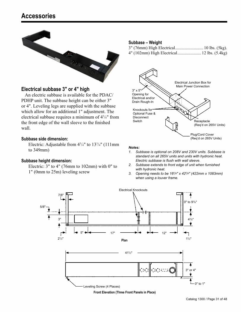
Electrical subbase 3" or 4" highAn electric subbase is available for the PDAC/
PDHP unit. The subbase height can be either 3" or 4". Leveling legs are supplied with the subbase which allow for an additional 1" adjustment. The electrical subbase requires a minimum of 43/8" from the front edge of the wall sleeve to the finished wall.
Subbase side dimension: Electric: Adjustable from 43/4" to 133/4" (111mm
to 349mm)
Subbase height dimension: Electric: 3" to 4" (76mm to 102mm) with 0" to
1" (0mm to 25m) leveling screw
Notes:1. Subbase is optional on 208V and 230V units. Subbase is
standard on all 265V units and units with hydronic heat. Electric subbase is flush with wall sleeve.2. Subbase extends to front edge of unit when furnished
with hydronic heat.3. Opening needs to be 165/8" x 425/8" (422mm x 1083mm)
when using a louver frame.
Subbase – Weight3" (76mm) High Electrical .......................... 10 lbs. (5kg).4" (102mm) High Electrical ...................... 12 lbs. (5.4kg)
Catalog 1300 / Page 32 of 48
Accessories
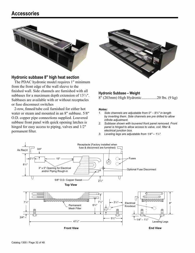
Hydronic subbase 8" high heat sectionThe PDAC hydronic model requires 1" minimum
from the front edge of the wall sleeve to the finished wall. Side channels are furnished with all subbases for a maximum depth extension of 133/4". Subbases are available with or without receptacles or fuse disconnect switches
2-row, finned/tube coil furnished for either hot water or steam and mounted in an 8" subbase. 5/8" O.D. copper pipe connections supplied. Louvered subbase front panel with quick opening latches is hinged for easy access to piping, valves and 1/2" permanent filter.
3/4"
Receptacle (Factory installed when fuse & disconnect are furnished)
As Req’d
Notes:1. Side channels are adjustable from 0" – 93/8" in length
by inverting them. Side channels are pre drilled to allow infinite adjustment.
2. Subbase shown with louvered front panel removed. Front panel is hinged to allow access to valve, coil, filter & electrical junction box.
3. Leveling legs are adjustable from 1/4" – 11/4".
21/2"
81/4"
21/2"
11/2"
1/4" – 11/4"
8"31/4"
�1/2"
71/2"63/4"
71/4"
3/4"411/2"
1�" Fuses
�/8" O.D. Copper Sweat
3" x �" Opening for Electrical and/or Piping Rough-in
Optional Fuse Disconnect
Permanent Mesh Filter
Electrical Knockout
TopView
FrontView EndView
Leveling Legs
Hydronic Subbase – Weight8" (203mm) High Hydronic ................20 lbs. (9 kg)
Catalog 1300 / Page 33 of 48
Accessories
Internal drain kit
Contractor To Drill Three (3) Holes
To Accept Drain Kit
Square Drain HolesNeoprene Sponge Gasket
Steel Mounting Plate
See Detail
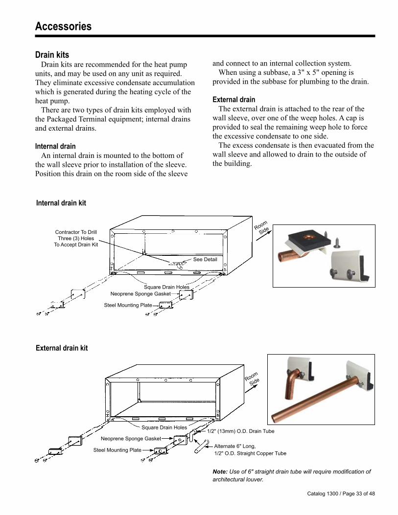
Note: Use of 6" straight drain tube will require modification of architectural louver.
Square Drain Holes
Neoprene Sponge Gasket
Steel Mounting Plate
Room
Side
1/2" (13mm) O.D. Drain Tube
Alternate 6" Long, 1/2" O.D. Straight Copper Tube
External drain kit
Drain kitsDrain kits are recommended for the heat pump
units, and may be used on any unit as required. They eliminate excessive condensate accumulation which is generated during the heating cycle of the heat pump.
There are two types of drain kits employed with the Packaged Terminal equipment; internal drains and external drains.
Internal drainAn internal drain is mounted to the bottom of
the wall sleeve prior to installation of the sleeve. Position this drain on the room side of the sleeve
and connect to an internal collection system.When using a subbase, a 3" x 5" opening is
provided in the subbase for plumbing to the drain.
External drainThe external drain is attached to the rear of the
wall sleeve, over one of the weep holes. A cap is provided to seal the remaining weep hole to force the excessive condensate to one side.
The excess condensate is then evacuated from the wall sleeve and allowed to drain to the outside of the building.
Room
Side
Catalog 1300 / Page 34 of 48
Accessories
Dimension 16" x 42" Slope top 16" x 44" Replacement Unit
A 111/8" 117/8" B 24" 2�" C 67/8" 7�/8"
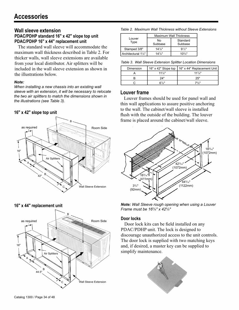
Wall sleeve extensionPDAC/PDHP standard 16" x 42" slope top unitPDAC/PDHP 16" x 44" replacement unit
The standard wall sleeve will accommodate the maximum wall thickness described in Table 2. For thicker walls, wall sleeve extensions are available from your local distributor. Air splitters will be included in the wall sleeve extension as shown in the illustrations below.
Table 2. Maximum Wall Thickness without Sleeve Extensions
Maximum Wall Thickness Louver No Standard Type Subbase Subbase
Stamped 3/8" 141/8" �1/2" Architectural 11/8" 147/8" 103/8"
Note: When installing a new chassis into an existing wall sleeve with an extension, it will be necessary to relocate the two air splitters to match the dimensions shown in the illustrations (see Table 3).
423/16"(1072mm)
163/16"(411mm)
33/4"(�2mm)
443/16"(1122mm)
183/16"(1072mm)
Note: Wall Sleeve rough opening when using a Louver Frame must be 165/8" x 425/8"
Louver frameLouver frames should be used for panel wall and
thin wall applications to assure positive anchoring to the wall. The cabinet/wall sleeve is installed flush with the outside of the building. The louver frame is placed around the cabinet/wall sleeve.
Door locksDoor lock kits can be field installed on any
PDAC/PDHP unit. The lock is designed to discourage unauthorized access to the unit controls. The door lock is supplied with two matching keys and, if desired, a master key can be supplied to simplify maintenance.
Wall Sleeve Extension
42"
Room Side
Air Splitters
as required
16"
16" x 42" slope top unit
Wall Sleeve Extension
Room Side
B
16"
B
B
B
A
C
A
C
44.�"
Air Splitters
16" x 44" replacement unit
Table 3. Wall Sleeve Extension Splitter Location Dimensions
as required
Catalog 1300 / Page 3� of 48
Accessories
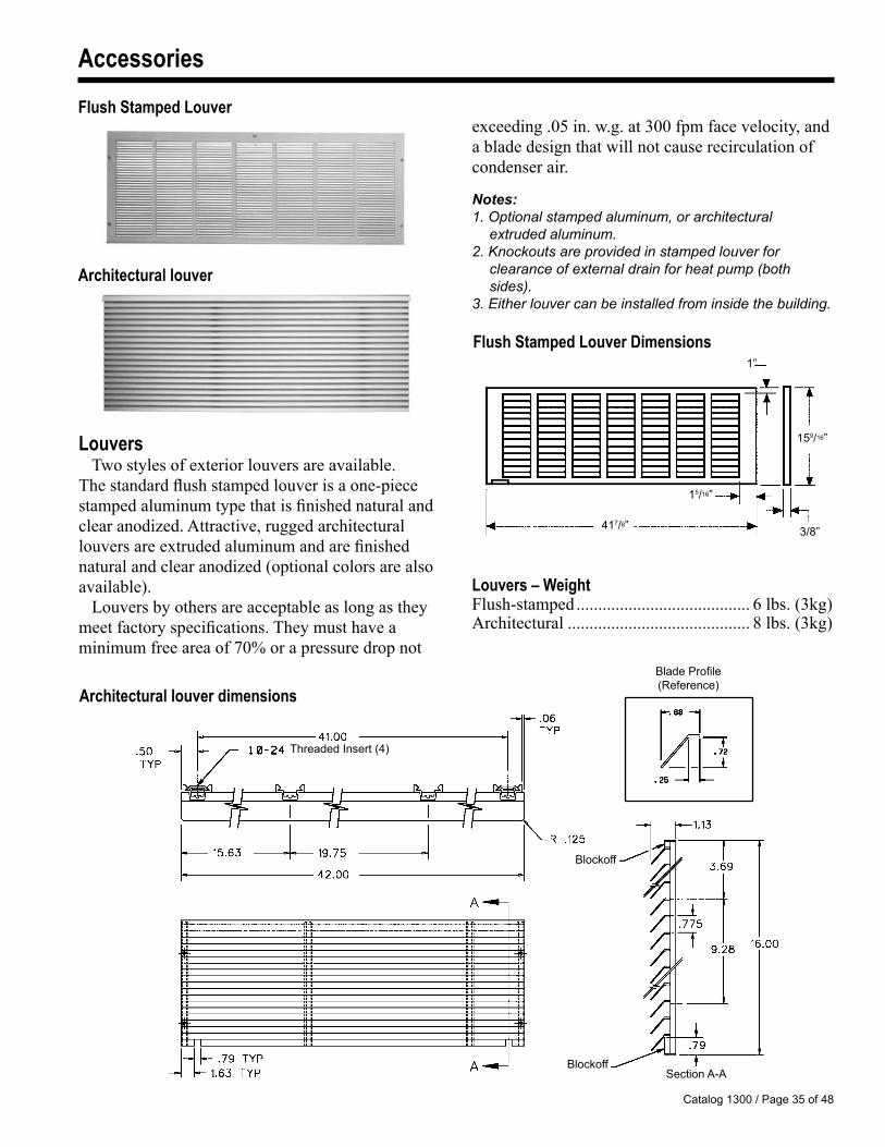
Flush Stamped Louver Dimensions
Louvers Two styles of exterior louvers are available.
The standard flush stamped louver is a one-piece stamped aluminum type that is finished natural and clear anodized. Attractive, rugged architectural louvers are extruded aluminum and are finished natural and clear anodized (optional colors are also available).
Louvers by others are acceptable as long as they meet factory specifications. They must have a minimum free area of 70% or a pressure drop not
Blade Profile (Reference)
Blockoff
BlockoffSection A-A
Threaded Insert (4)
Architectural louver dimensions
Notes:1. Optional stamped aluminum, or architectural
extruded aluminum.2. Knockouts are provided in stamped louver for
clearance of external drain for heat pump (both sides).
3. Either louver can be installed from inside the building.
1��/16”
3/8”
1�/16”
417/8”
1”
Flush Stamped Louver
Architectural louver
exceeding .05 in. w.g. at 300 fpm face velocity, and a blade design that will not cause recirculation of condenser air.
Louvers – WeightFlush-stamped ........................................ 6 lbs. (3kg)Architectural .......................................... 8 lbs. (3kg)
Catalog 1300 / Page 36 of 48
Wiring Diagrams
B
Jumper Placement Detail
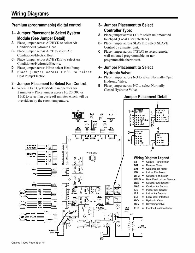
Premium (programmable) digital control
1– Jumper Placement to Select System Module (See Jumper Detail) A– Place jumper across AC/HYD to select Air Conditioner/Hydronic Heat.B– Place jumper across AC/E to select Air Conditioner/Electric Heat.C– Place jumper across AC/HYD/E to select Air Conditioner/Hydronic/Electric.D– Place jumper across HP to select Heat PumpE– P l a c e j u m p e r a c r o s s H P / E t o s e l e c t Heat Pump/Electric.
2– Jumper Placement to Select Fan Control: A– When in Fan Cycle Mode, fan operates for
2 minutes – Place jumper across 10, 20, 30, or 1 HR to select fan cycle off minutes which will be overridden by the room temperature.
3– Jumper Placement to Select Controller Type:A– Place jumper across LUI to select unit mounted touchpad (Local User Interface).B– Place jumper across SLAVE to select SLAVE Control by a master unit. C– Place jumper across T’STAT to select remote, wall mounted programmable, or non- programmable thermostat.
4– Jumper Placement to Select Hydronic Valve:A– Place jumper across NO to select Normally Open Hydronic Valve. B– Place jumper across NC to select Normally Closed Hydronic Valve.
3
2
1
CA
4DE
A
A
BC
AB
Wiring Diagram LegendCT = Control TransformerDM = Damper MotorCM = Compressor MotorIFM = Indoor Fan MotorOFM = Outdoor Fan MotorHFLO= Heat Fan Lockout SensorOCS = Outdoor Coil SensorOAS = Outdoor Air SensorICS = Indoor Coil SensorIAS = Indoor Air SensorLUI = Local User InterfaceHYV = Hydronic ValveREV = Reversing ValveEHC = Electric Heat Contactor
Catalog 1300 / Page 37 of 48
Wiring Diagrams
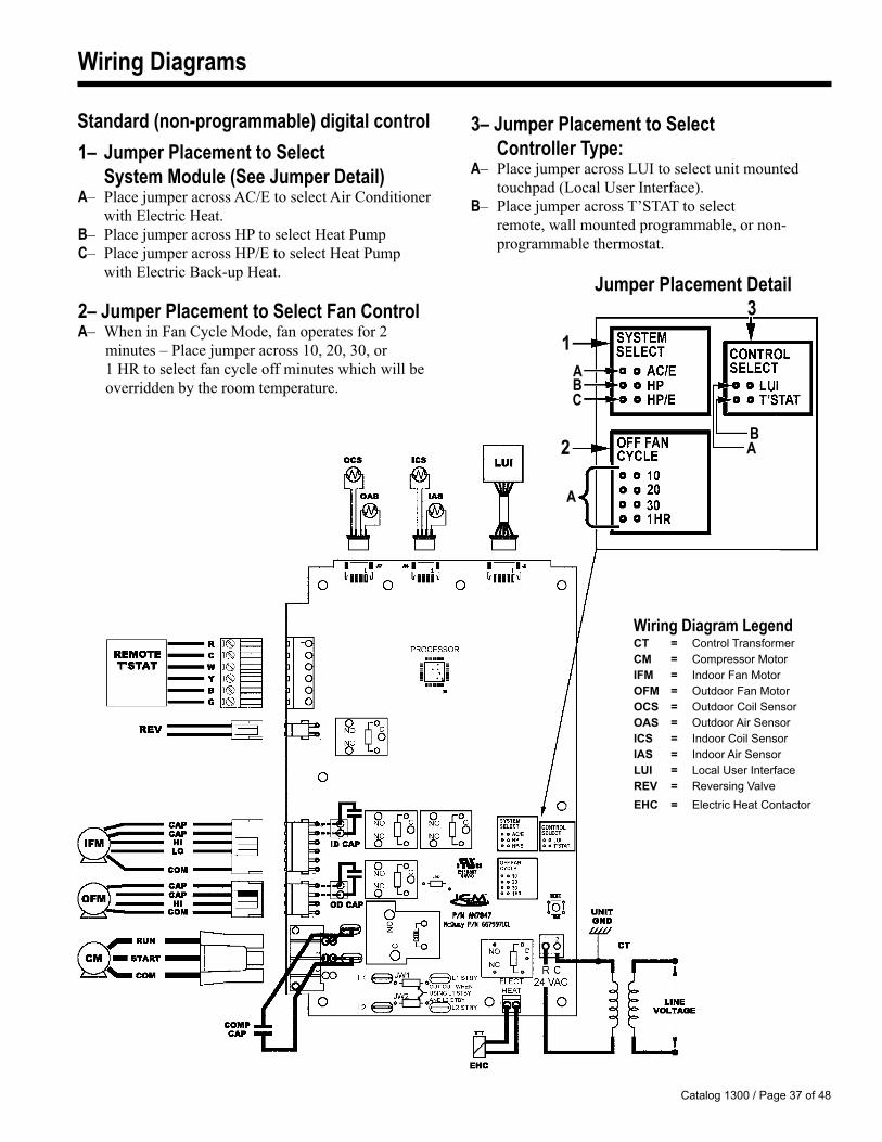
Standard (non-programmable) digital control 3– Jumper Placement to Select Controller Type:A– Place jumper across LUI to select unit mounted touchpad (Local User Interface).B– Place jumper across T’STAT to select remote, wall mounted programmable, or non- programmable thermostat.
3
2
1
Jumper Placement Detail
C
AB
A
BA
Wiring Diagram LegendCT = Control TransformerCM = Compressor MotorIFM = Indoor Fan MotorOFM = Outdoor Fan MotorOCS = Outdoor Coil SensorOAS = Outdoor Air SensorICS = Indoor Coil SensorIAS = Indoor Air SensorLUI = Local User InterfaceREV = Reversing ValveEHC = Electric Heat Contactor
1– Jumper Placement to Select System Module (See Jumper Detail)A– Place jumper across AC/E to select Air Conditioner with Electric Heat.B– Place jumper across HP to select Heat PumpC– Place jumper across HP/E to select Heat Pump with Electric Back-up Heat.
2– Jumper Placement to Select Fan ControlA– When in Fan Cycle Mode, fan operates for 2
minutes – Place jumper across 10, 20, 30, or 1 HR to select fan cycle off minutes which will be overridden by the room temperature.
Catalog 1300 / Page 38 of 48
Wiring Diagrams
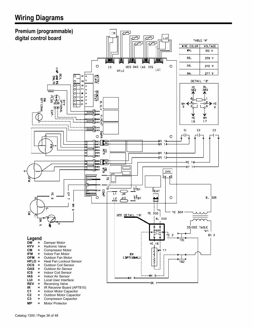
LegendDM = Damper MotorHYV = Hydronic ValveCM = Compressor MotorIFM = Indoor Fan MotorOFM = Outdoor Fan MotorHFLO= Heat Fan Lockout SensorOCS = Outdoor Coil SensorOAS = Outdoor Air SensorICS = Indoor Coil SensorIAS = Indoor Air SensorLUI = Local User InterfaceREV = Reversing ValveIR = IR Receiver Board (AP7810)C1 = Indoor Motor CapacitorC2 = Outdoor Motor CapacitorC3 = Compressor CapacitorMP = Motor Protector
Premium (programmable) digital control board
Catalog 1300 / Page 3� of 48
Wiring Diagrams
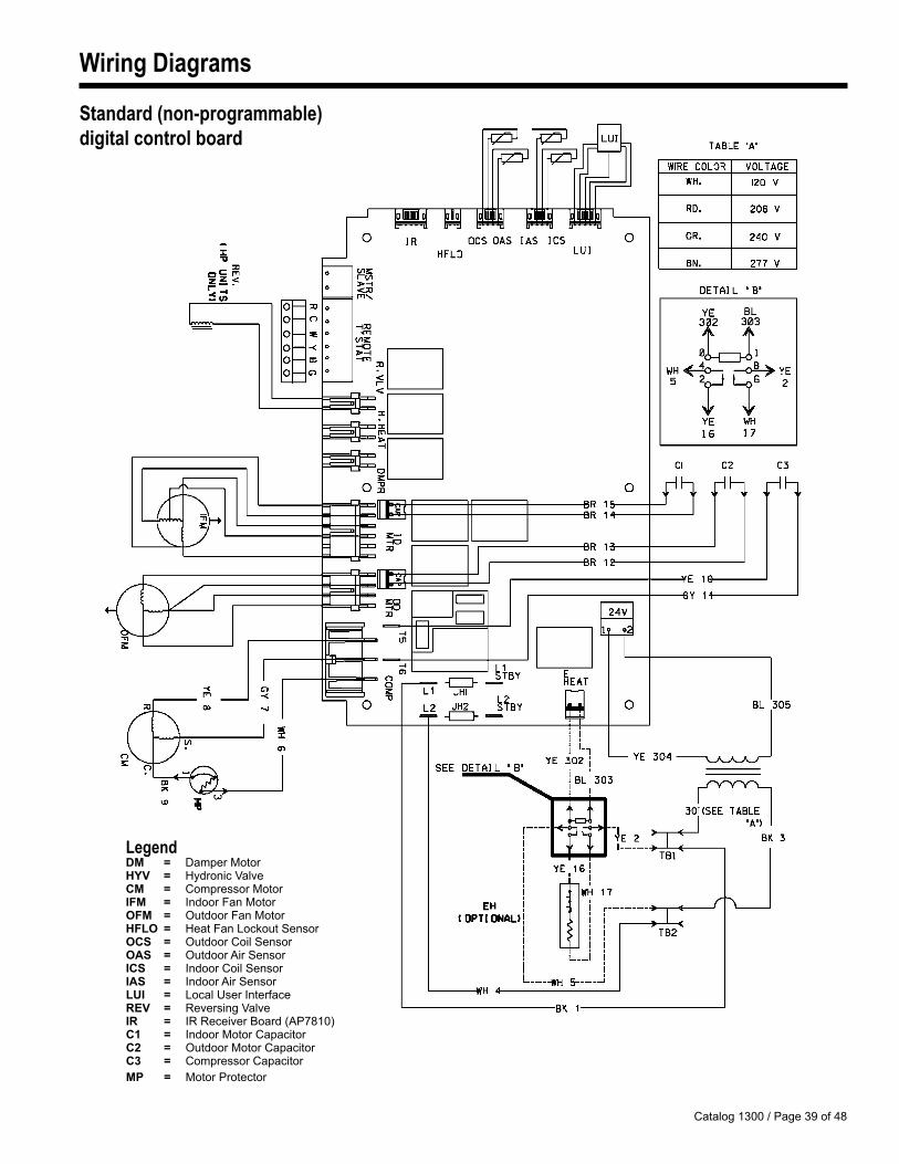
LegendDM = Damper MotorHYV = Hydronic ValveCM = Compressor MotorIFM = Indoor Fan MotorOFM = Outdoor Fan MotorHFLO= Heat Fan Lockout SensorOCS = Outdoor Coil SensorOAS = Outdoor Air SensorICS = Indoor Coil SensorIAS = Indoor Air SensorLUI = Local User InterfaceREV = Reversing ValveIR = IR Receiver Board (AP7810)C1 = Indoor Motor CapacitorC2 = Outdoor Motor CapacitorC3 = Compressor CapacitorMP = Motor Protector
Standard (non-programmable) digital control board
Catalog 1300 / Page 40 of 48
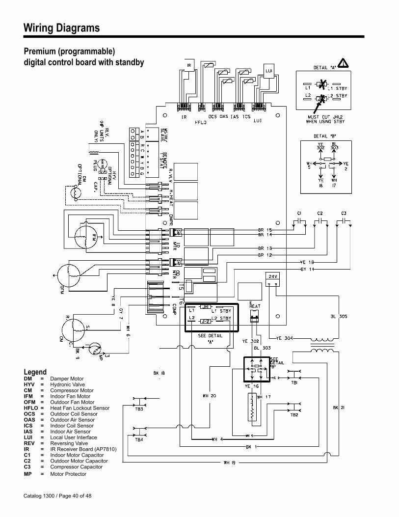
Wiring Diagrams
LegendDM = Damper MotorHYV = Hydronic ValveCM = Compressor MotorIFM = Indoor Fan MotorOFM = Outdoor Fan MotorHFLO= Heat Fan Lockout SensorOCS = Outdoor Coil SensorOAS = Outdoor Air SensorICS = Indoor Coil SensorIAS = Indoor Air SensorLUI = Local User InterfaceREV = Reversing ValveIR = IR Receiver Board (AP7810)C1 = Indoor Motor CapacitorC2 = Outdoor Motor CapacitorC3 = Compressor CapacitorMP = Motor Protector
Premium (programmable) digital control board with standby
Catalog 1300 / Page 41 of 48
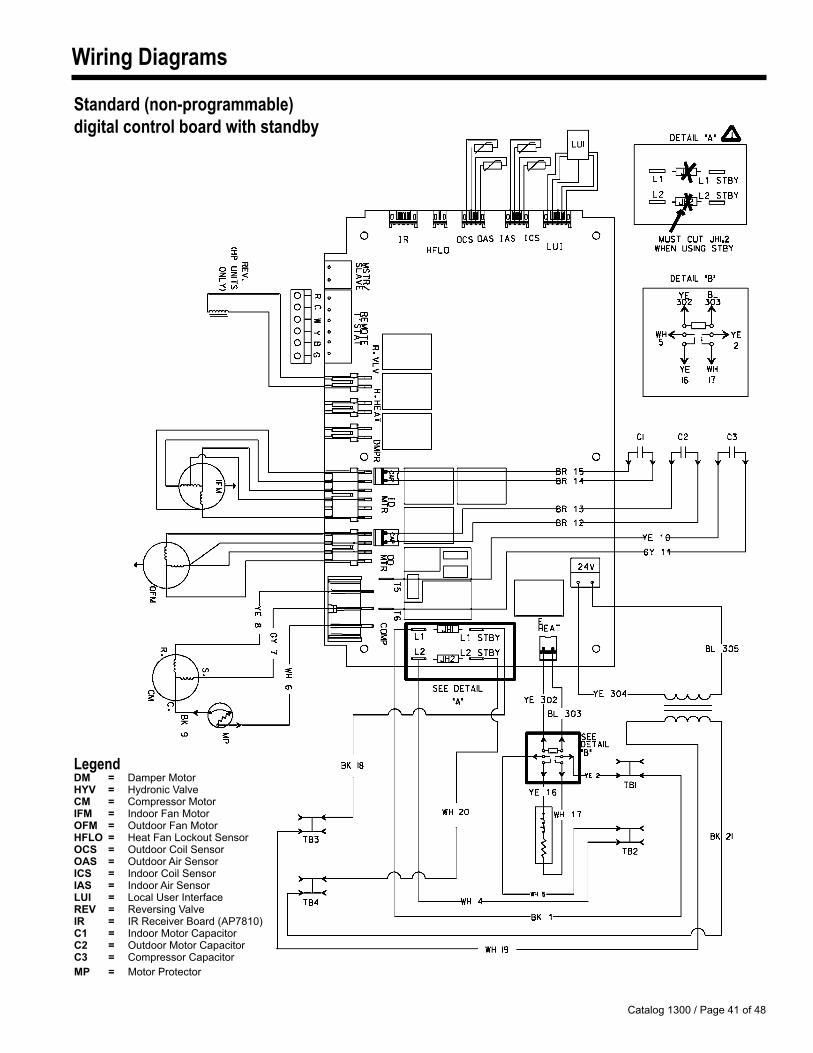
Wiring Diagrams
Standard (non-programmable) digital control board with standby
LegendDM = Damper MotorHYV = Hydronic ValveCM = Compressor MotorIFM = Indoor Fan MotorOFM = Outdoor Fan MotorHFLO= Heat Fan Lockout SensorOCS = Outdoor Coil SensorOAS = Outdoor Air SensorICS = Indoor Coil SensorIAS = Indoor Air SensorLUI = Local User InterfaceREV = Reversing ValveIR = IR Receiver Board (AP7810)C1 = Indoor Motor CapacitorC2 = Outdoor Motor CapacitorC3 = Compressor CapacitorMP = Motor Protector
Catalog 1300 / Page 42 of 48
Engineering Guide Specifications – 16" x 42" Slope Top ConfigurationFurnish and install where shown on plans (packaged terminal air conditioners) (packaged terminal heat pumps) of
the sizes and capacities shown on the schedule. The units shall be located as shown on the drawings and shall include cabinet/wall sleeve, chassis, outdoor louver, and room cabinet. (Units furnished with hydronic heat shall also include a hydronic subbase, valve and appropriate controls).
All units shall be UL listed for safety and ETL certified for performance. Units shall be McQuay Comfort Conditioner, PDAC/PDHP, or equal. Overall dimensions for the basic unit shall not exceed 421/2" wide, 161/2" high, and 22" deep. (Overall dimensions of the wall sleeve shall not exceed 16" high, 42" wide and 133/4" deep).
(Units furnished with hydronic heat shall not exceed 43" wide, 241/2" high and 20" deep). (Units furnished with an electrical subbase shall not exceed 43" wide, 241/2" high and 22" deep). All units shall operate on ____ volts, 60 Hz, single-phase power. The minimum energy efficiency ratio (EER) in BTU per hour per watt for each (PDAC) (PDHP) unit must be in
compliance with ASHRAE 90.1 replacement or new construction criteria, for all sizes. (The minimum COP for heat pumps, at 47oF DB outdoor, must be 2.9 for all sizes).
Heating/Cooling chassis – Chassis shall be slide-in, plug-in type with a self-contained, hermetically sealed refrigerant circuit. All chassis sheet metal parts shall be constructed of either powder-coated A-60 or G-60 galvanized steel for maximum corrosion resistance. The chassis shall consist of the following components:
Vibration isolated compressor; rifled copper tubed evaporator and condenser coils with high efficiency raised lance aluminum plate fins mechanically expanded to the tubes for maximum heat transfer; and a capillary restrictor type refrigerant metering device. Coils shall be factory tested at 300 psig. (Heat pump models shall also include reversing valve and charge balancing device). A positive closing (manual) fresh air damper may be located within the chassis to provide fresh air during fan operation.
Airflow system shall include separate fan motors for the condenser and evaporator sections. The condenser fan motor shall be a single-speed, totally enclosed, permanently lubricated fan motor. Condenser fan shall be propeller-type with a slinger ring and shall be constructed of aluminum. The indoor fan motor shall be a two-speed, totally enclosed; permanently lubricated fan motor must be positioned on the indoor side of the bulkhead so as to be completely within the conditioned, filtered airstream. The indoor blower fan shall be a forward-curved tangential design to provide even airflow across the evaporator coil.
During the cooling cycle:The compressor, the outdoor fan motor and the indoor fan motor shall be energized. Condensation accumulated on
the evaporator coil shall be drained into the outdoor section where it is to be picked up by the condenser fan/slinger ring and evaporated against the outdoor coil. In the cool mode, the compressor will cut in if the space temperature is at least 1°F above the thermostat set point and will cut out when the space temperature is approximately 2°F below set point, subject to timing protections.
During the heating cycle:Electric Resistance Heat – Control will call for electric heat when the space temperature is 1°F lower that the set
point. The control will cease its call when the space temperature is 3°F or higher than set point.Only the indoor fan motor and electric resistance heater are energized. The outdoor condenser fan motor and
compressor shall not be energized. Heater shall be open wire type with quick response and high limit cutout. Heaters shall be sized to meet heating requirements as shown on the schedule. Electric resistance heaters must be placed behind the indoor evaporator coil and must not be visible through the indoor discharge grille. When the heater cuts out the indoor fan continues to run for 15 seconds at the set speed, regardless of On or Off mode. After 15 seconds the fan will stop running if unit is in Off mode, else the fan operation will depend on Fan Continuous or Fan Cycle setting.
Hydronic, Hot water or Steam, heat – Only the indoor fan motor, the (normally open) (normally closed) valve and automatic fresh air damper shall be energized. The outdoor condenser fan motor and compressor shall not be energized.
Catalog 1300 / Page 43 of 48
Engineering Guide Specifications – 16" x 42" Slope Top ConfigurationHeat Fan Lock Out – When the control is in the heat mode and calling for heat, the indoor fan shall not turn on
until the HFLO sensor is above 115°F. If at any time while the unit is in heat mode the HFLO sensor is below 95°F, the indoor fan shall turn off immediately. Control will check if the HFLO sensor temperature is above 115°F for 2 seconds before resuming indoor fan operation.
Hydronic with Intermediate Electric heat – Upon the call for heating and thereafter the HFLO sensor temperature will be monitored. A trend in HFLO sensor Temperature shall determine which form of heat is to be used. If during the 90 seconds that Hydronic is the heat source and the HFLO sensor is above 105°F and is increasing at 2°F per minute then Hydronic is the heat source. If during this 90 seconds, the temperature of the HFLO sensor is above 105°F and is not increasing at 2°F per minute then Electric is the heat source. The hydronic valve is opened for 90 seconds. After 90 seconds whether Hydronic or Electric provides the heating is determined by the following:
If HFLO sensor temperature is less that 105°F, Electric provides the heat.If HFLO sensor temperature is greater than 115°F, Hydronic provides the heat
Reverse Cycle Heat Pump with back-up electric heat – The reversing valve, the compressor, the outdoor condenser fan motor and the indoor fan motor shall be energized. Reverse cycle heating shall occur when the outdoor temperatures are 35°F and above. If outdoor coil temperature drops below 20°F or the Outdoor air temperature drops to 35°F or less, Electric heat is the only source of heat. When the Outdoor coil temperature raises back to 40°F and above, then the Compressor or Electric heater is used.
A temperature-sensing device shall be used to monitor the outdoor coil temperature to limit frost buildup. Defrosting of the outdoor coil will be activated when outdoor coil temperature drops below 20°F of outdoor air temperature drops to 35°F or less. Defrosting is terminated when outdoor coil temperature rises back to 40°F. During defrosting, both compressor and the outdoor fan are turned off. The indoor fan will run at its set speed.
Condensation accumulated during reverse cycle heating must NOT be evaporated against the indoor coil so as to prevent contamination of the indoor air with pollutants and odors. Condensation must be disposed of using a (external) (internal) drain system as shown on plans.
Control module – The PDAC/HP Control module is used to control a PDAC or PDHP unit that includes both an integral air conditioner and a source of heat. The Digital Control is operated with a Touchpad, IR Remote or 24 volt, Wall Mounted Thermostat.
Inputs and outputs The PDAC/HP control module offers the following inputs:1. Indoor Coil Sensor (ICS)2. Indoor Air Sensor (IAS)3. Outdoor Air Sensor (OAS)4. Inputs from Remote Thermostat (R, B, G, Y, W)5. Heat Fan Lock Out Sensor (HFLO)6. Power Supply, 24VAC
The PDAC/HP control module offers the following outputs:1. Compressor Output (COM)2. Outdoor Fan (FAN)3. Indoor Fan Fan cycle or Fan Continuous and Blower Hi or Blower Lo shall be incorporated to allow either continuous or automatic fan cycle operation at the selected fan speed. When choosing automatic fan cycle operation, the fan shall be energized only when the compressor or electric resistance heaters are energized. 4. Damper Control (DAMPER)5. Hydronic Valve (HYV)
Catalog 1300 / Page 44 of 48
Engineering Guide Specifications – 16" x 42" Slope Top Configuration
On heat pump models, a Low Ambient temperature limit Sensor (OAS) shall be incorporated to energize the electric resistance heaters at 35°F outdoor air temperature.
Room cabinet – Shall be sloped top, wraparound design with an 18-gauge front panel that is phosphatized and coated with baked on urethane powder paint, corrosion resistant finish to match the wall sleeve. Side panels shall be constructed of polycarbonate material with decorative vertical grooves and flame class rated at 94V per UL standard 494.
Discharge grille – Shall be an integral part of the front panel and shall be a raised style. Discharge grille shall be made of the same polycarbonate material as the room cabinet side panels. Grille shall be sectional, two-position reversible, tamper proof, and carry a flame test rating of 94V0 in accordance with UL standard 494.
Control access door – Shall be mounted on the right-hand side and must meet the spillage requirements of UL standard 484.
Filtration (Standard) – Room side return air shall be completely filtered through a permanent, washable polypropylene mesh filter. Foam type filters are not acceptable. Filter must be a UL listed class II, 38% average arrestance efficiency (ASHRAE test) air filter with low resistance to airflow (0.02 w.g. at 300 CFM) and high dust holding capacity of 55 grams.
Filtration (Optional) – Room side return air shall be completely filtered through a permanent, washable polypropylene mesh filter. Foam type filters are not acceptable. Filter must be a UL listed class II, 72% average arrestance efficiency (ASHRAE test) air filter with low resistance to airflow (0.03 w.g. at 300 CFM) and high dust holding capacity of 100 grams.
Wall Sleeve (Standard) (BWS) –The BWS wall sleeve is constructed from galvanized, primed and pre-painted Antique Ivory 18 gauge steel is
insulated and arrives in a removable plastic protective film.
Wall Sleeve (Optional) (CWS) – The CWS wall sleeve shall be entirely constructed of G-60 galvanized, phosphatized, 18-gauge steel. It shall be finished with a baked on, epoxy based powder coat paint, which is to provide maximum corrosion protection. Additionally, the top interior and side interior surfaces shall be insulated. Wall sleeves with ordinary enamel finish or those made from polymeric material are not acceptable. Wall sleeves shall have factory provisions for use of appropriate fastening devices to secure sleeve to the wall through the sides.
Catalog 1300 / Page 4� of 48
Engineering Guide Specifications – 16" x 42" Slope Top Configuration
Outside air louvers – Shall be (stamped) (architectural) anodized aluminum as shown on plans. Louver shall be (finished natural) (painted) as shown on the schedule. (Stamped louvers shall be heavy gauge anodized aluminum of no less than 16-gauge). (Architectural louvers shall have rounded corners or be supplied with end caps). Special field fabricated louvers must be approved by the PTAC manufacturer as to free area and air circulation requirements.
Subbase (electrical) – An (3")(4") electrical subbase shall be furnished as shown on plans. Each electrical subbase shall be UL listed and conform to the National Electrical Code. Subbase must have adjustable side channels with predrilled adjusting holes and score lines. Subbase shall have four (4) adjustable leveling legs each with 1" adjustment.
Subbase (hydronic) – An 8" high, hydronic heating subbase shall be furnished as shown on plans. Subbase shall contain a 2-row, 5/8" diameter copper tubed, aluminum plate finned coil for use with hot water or steam; (normally open) (normally closed), low voltage electric valve for (hot water) (steam) heating; and provisions for mounting a receptacle. (Subbase must be supplied with factory installed fuse and disconnect sized for PTAC unit ampacity rating.) The subbase must have adjustable side channels capable of extending to any wall thickness. The subbase shall have six (6) adjustable leveling legs each with 1" adjustment.
© 2007 McQuay International • www.mcquay.com • 800-432-1342 Catalog 1300 / (�-07)
®
Warranty
All McQuay equipment is sold pursuant to its standard terms and conditions of sale, including LimitedProduct Warranty. Consult your local McQuay Representative for warranty details. Refer to Form933-43285Y. To find your local McQuay Representative, go to www.mcquay.com.
This document contains the most current product information as of this printing. For the most up-to-dateproduct information, please go to www.mcquay.com.