Embed Size (px)
Citation preview
Henryk AnglartNuclear Reactor Technology Division
Department of Energy Technology, KTH
Applied Reactor Technology and Nuclear Power Safety - Lecture 7 Slide No 1
Lectures on Applied Reactor Technology and Nuclear Power Safety
Lecture No 7
Title: Thermal-Hydraulic Analysis of Single-Phase Flows in Heated Channels
Henryk AnglartNuclear Reactor Technology Division
Department of Energy TechnologyKTH
Spring 2005
Henryk AnglartNuclear Reactor Technology Division
Department of Energy Technology, KTH
Applied Reactor Technology and Nuclear Power Safety - Lecture 7 Slide No 2
Outline of the Lecture• Clad-Coolant Heat Transfer in Channels with Single
Phase Flows
• Coolant Enthalpy Distribution in Heated Channels
• Temperature Distribution in Fuel Elements
• Pressure Distribution in Channels with Single-Phase Flow
Henryk AnglartNuclear Reactor Technology Division
Department of Energy Technology, KTH
Applied Reactor Technology and Nuclear Power Safety - Lecture 7 Slide No 3
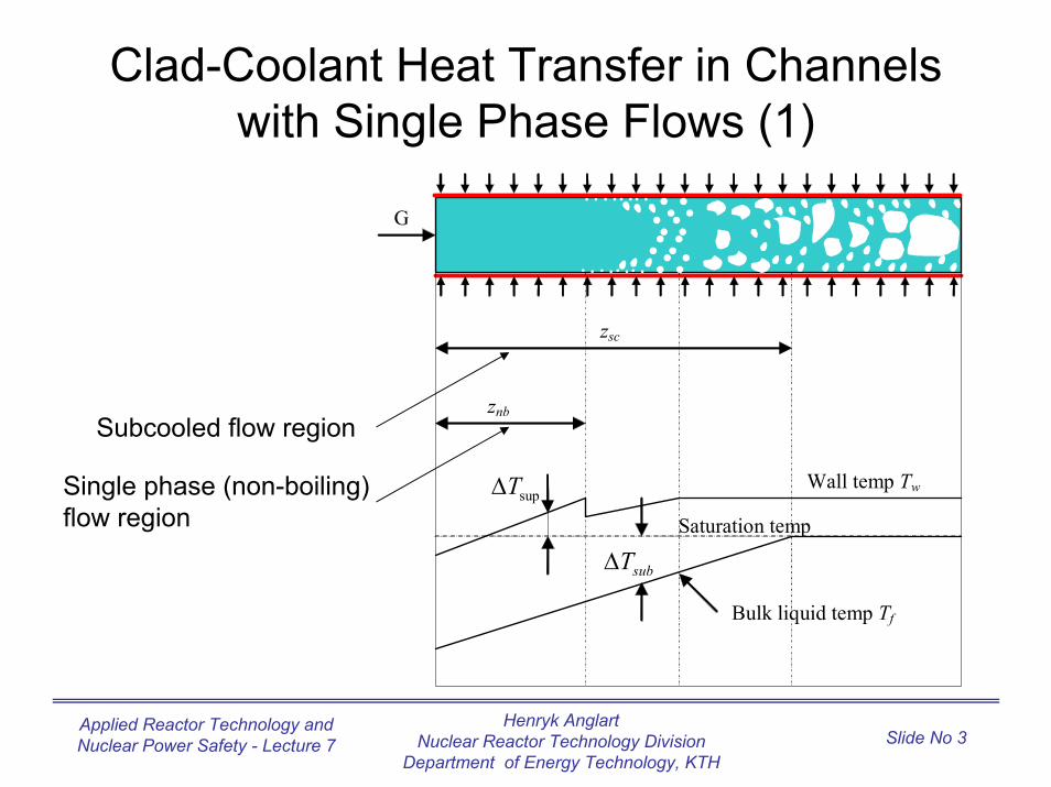
Clad-Coolant Heat Transfer in Channels with Single Phase Flows (1)
Wall temp Tw
Bulk liquid temp Tf
zsc
znb
supT∆
subT∆
G
Saturation temp
Single phase (non-boiling) flow region
Subcooled flow region
Henryk AnglartNuclear Reactor Technology Division
Department of Energy Technology, KTH
Applied Reactor Technology and Nuclear Power Safety - Lecture 7 Slide No 4
Clad-Coolant Heat Transfer in Channels with Single Phase Flows (2)
• In Light Water Reactors, coolant is subcooled at the inlet to the reactor core
• The subcooling is defined as the difference between the saturation temperature and the actual coolant temperature
• For example, if the inlet temperature and pressure of the water coolant are 549 K and 7 MPa, respectively, then the inlet subcooling is equal to 559 K – 549 K = 10 K, since the saturation temperature of water at 7 MPapressure is equal to 559 K
Henryk AnglartNuclear Reactor Technology Division
Department of Energy Technology, KTH
Applied Reactor Technology and Nuclear Power Safety - Lecture 7 Slide No 5
Clad-Coolant Heat Transfer in Channels with Single Phase Flows (3)
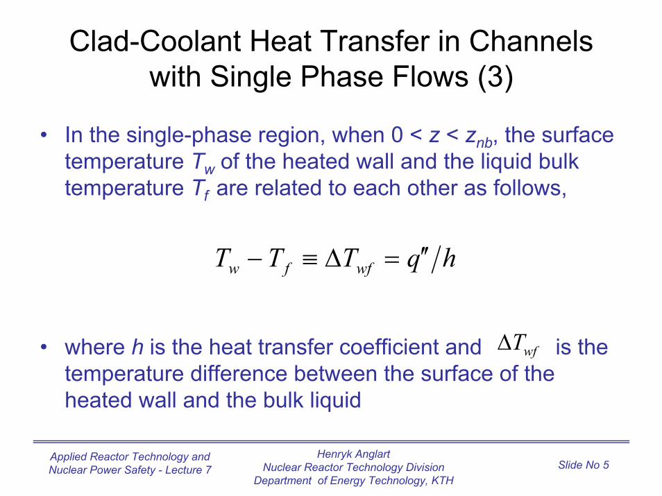
• In the single-phase region, when 0 < z < znb, the surface temperature Tw of the heated wall and the liquid bulk temperature Tf are related to each other as follows,
• where h is the heat transfer coefficient and is the temperature difference between the surface of the heated wall and the bulk liquid
hqTTT wffw ′′=∆≡−
wfT∆
Henryk AnglartNuclear Reactor Technology Division
Department of Energy Technology, KTH
Applied Reactor Technology and Nuclear Power Safety - Lecture 7 Slide No 6
Clad-Coolant Heat Transfer in Channels with Single Phase Flows (4)
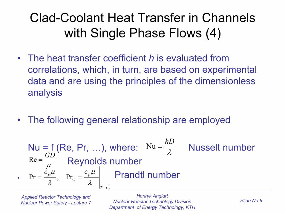
• The heat transfer coefficient h is evaluated from correlations, which, in turn, are based on experimental data and are using the principles of the dimensionless analysis
• The following general relationship are employed
Nu = f (Re, Pr, …), where: Nusselt numberReynolds number
, Prandtl number
λhD
=Nu
µGD
=Re
TT
pw
p cc
=
==λµ
λµ
Pr,Prw
Henryk AnglartNuclear Reactor Technology Division
Department of Energy Technology, KTH
Applied Reactor Technology and Nuclear Power Safety - Lecture 7 Slide No 7
Clad-Coolant Heat Transfer in Channels with Single Phase Flows (5)
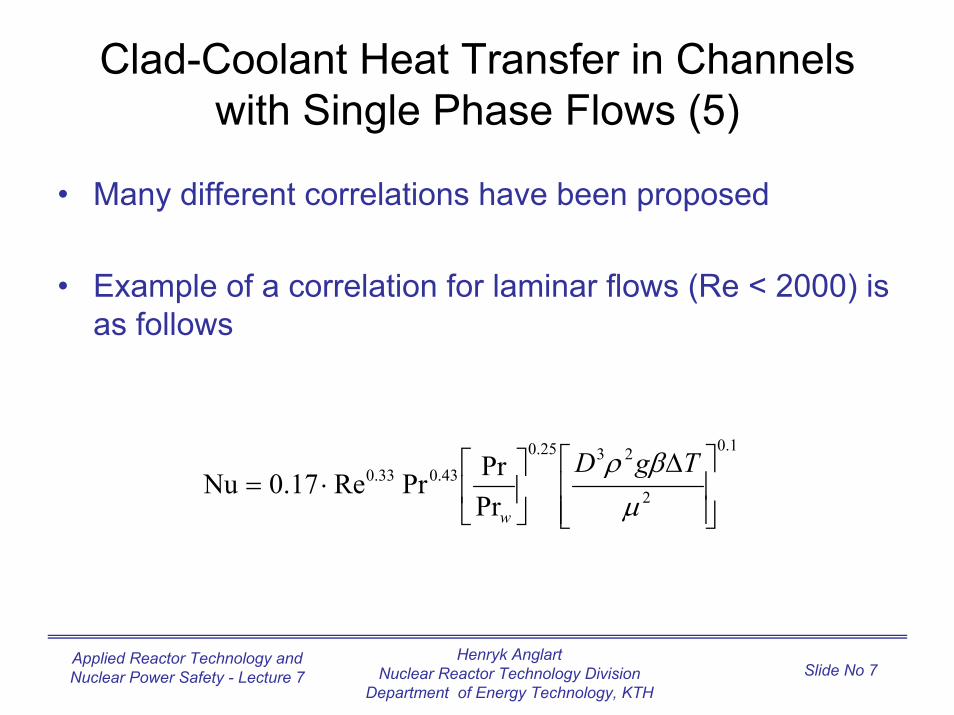
• Many different correlations have been proposed
• Example of a correlation for laminar flows (Re < 2000) is as follows
1.0
2
2325.043.033.0
PrPrPrRe17.0Nu
∆
⋅=
µβρ TgD
w
Henryk AnglartNuclear Reactor Technology Division
Department of Energy Technology, KTH
Applied Reactor Technology and Nuclear Power Safety - Lecture 7 Slide No 8
Clad-Coolant Heat Transfer in Channels with Single Phase Flows (6)
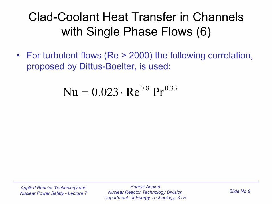
• For turbulent flows (Re > 2000) the following correlation, proposed by Dittus-Boelter, is used:
33.08.0 PrRe023.0Nu ⋅=
Henryk AnglartNuclear Reactor Technology Division
Department of Energy Technology, KTH
Applied Reactor Technology and Nuclear Power Safety - Lecture 7 Slide No 9
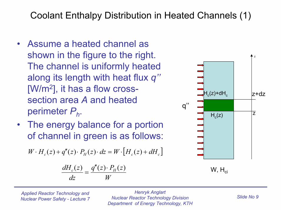
Coolant Enthalpy Distribution in Heated Channels (1)
• Assume a heated channel as shown in the figure to the right. The channel is uniformly heated along its length with heat flux q’’[W/m2], it has a flow cross-section area A and heated perimeter Ph.
• The energy balance for a portion of channel in green is as follows:
z
z+dz
W, Hci
Hc(z)+dHc
z
q’’Hc(z)
[ ]ccHc dHzHWdzzPzqzHW +⋅=⋅⋅′′+⋅ )()()()(
WzPzq
dzzdH Hc )()()( ⋅′′
=
Henryk AnglartNuclear Reactor Technology Division
Department of Energy Technology, KTH
Applied Reactor Technology and Nuclear Power Safety - Lecture 7 Slide No 10
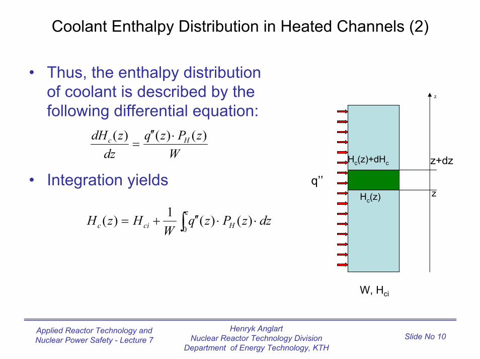
Coolant Enthalpy Distribution in Heated Channels (2)
• Thus, the enthalpy distribution of coolant is described by the following differential equation:
• Integration yieldsz
z+dz
W, Hci
Hc(z)+dHc
z
q’’Hc(z)
WzPzq
dzzdH Hc )()()( ⋅′′
=
dzzPzqW
HzHz
Hcic ⋅⋅′′+= ∫0 )()(1)(
Henryk AnglartNuclear Reactor Technology Division
Department of Energy Technology, KTH
Applied Reactor Technology and Nuclear Power Safety - Lecture 7 Slide No 11
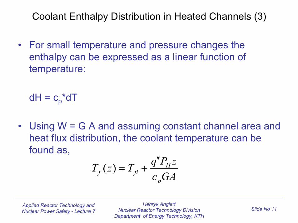
Coolant Enthalpy Distribution in Heated Channels (3)
• For small temperature and pressure changes the enthalpy can be expressed as a linear function of temperature:
dH = cp*dT
• Using W = G A and assuming constant channel area and heat flux distribution, the coolant temperature can be found as,
GAczPqTzT
p
Hfif
′′+=)(
Henryk AnglartNuclear Reactor Technology Division
Department of Energy Technology, KTH
Applied Reactor Technology and Nuclear Power Safety - Lecture 7 Slide No 12
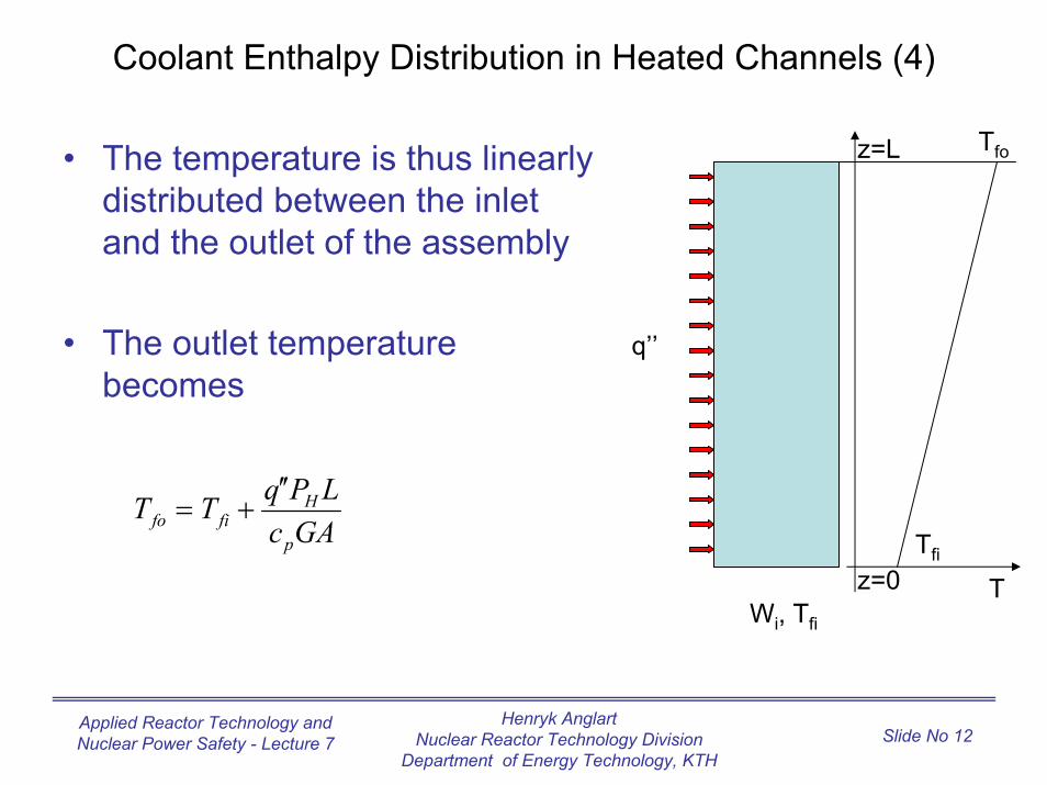
Coolant Enthalpy Distribution in Heated Channels (4)
• The temperature is thus linearly distributed between the inlet and the outlet of the assembly
• The outlet temperature becomes
z=L
z=0Tfi
Tfo
q’’
GAcLPqTT
p
Hfifo
′′+=
TWi, Tfi
Henryk AnglartNuclear Reactor Technology Division
Department of Energy Technology, KTH
Applied Reactor Technology and Nuclear Power Safety - Lecture 7 Slide No 13
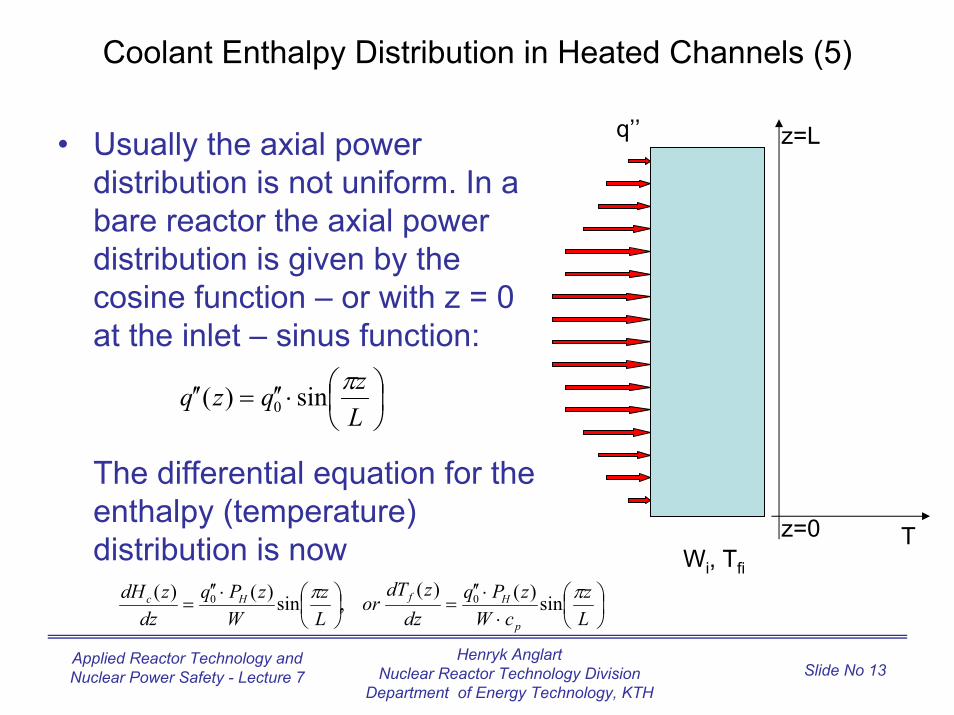
Coolant Enthalpy Distribution in Heated Channels (5)
q’’ z=L
z=0
• Usually the axial power distribution is not uniform. In a bare reactor the axial power distribution is given by the cosine function – or with z = 0 at the inlet – sinus function:
The differential equation for the enthalpy (temperature) distribution is now
⋅′′=′′
Lzqzq πsin)( 0
TWi, Tfi
⋅⋅′′
=
⋅′′
=Lz
cWzPq
dzzdT
orLz
WzPq
dzzdH
p
HfHc ππ sin)()(,sin)()( 00
Henryk AnglartNuclear Reactor Technology Division
Department of Energy Technology, KTH
Applied Reactor Technology and Nuclear Power Safety - Lecture 7 Slide No 14
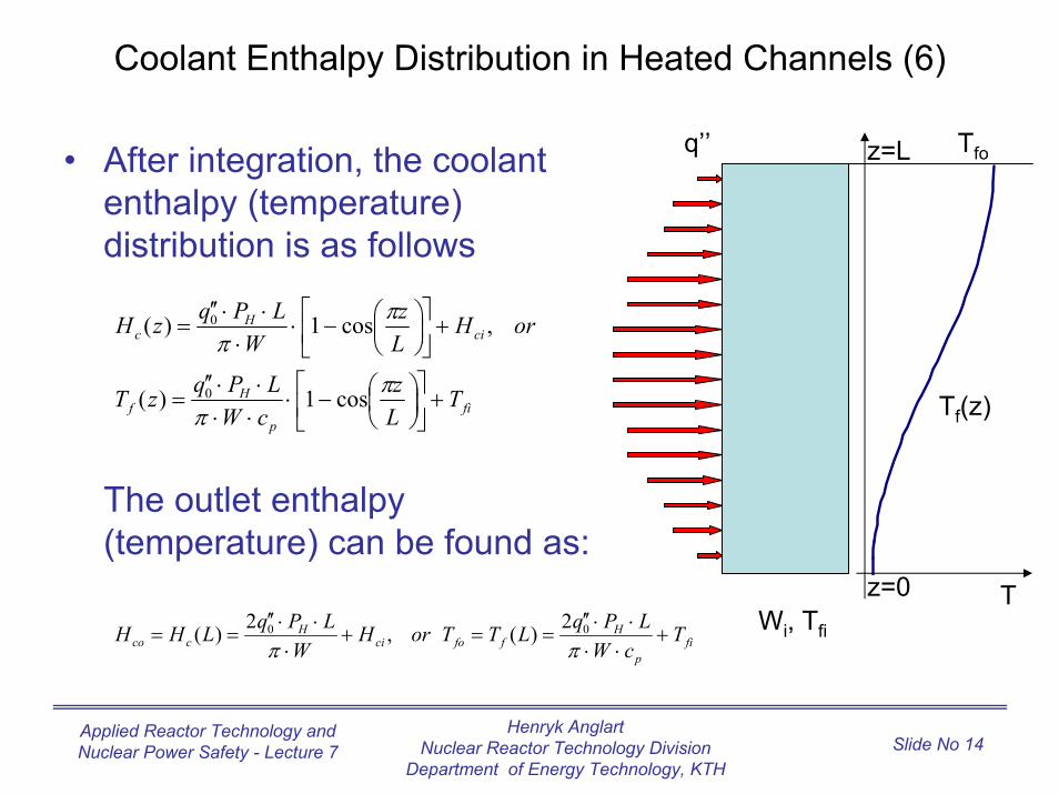
Coolant Enthalpy Distribution in Heated Channels (6)
• After integration, the coolant enthalpy (temperature) distribution is as follows
The outlet enthalpy (temperature) can be found as:
fip
Hf
ciH
c
TLz
cWLPqzT
orHLz
WLPqzH
+
−⋅
⋅⋅⋅⋅′′
=
+
−⋅
⋅⋅⋅′′
=
ππ
ππ
cos1)(
,cos1)(
0
0
fip
Hffoci
Hcco T
cWLPqLTTorH
WLPqLHH +
⋅⋅⋅⋅′′
==+⋅
⋅⋅′′==
ππ00 2)(,2)(
q’’ z=L
Tz=0
Tf(z)
Tfo
Wi, Tfi
Henryk AnglartNuclear Reactor Technology Division
Department of Energy Technology, KTH
Applied Reactor Technology and Nuclear Power Safety - Lecture 7 Slide No 15
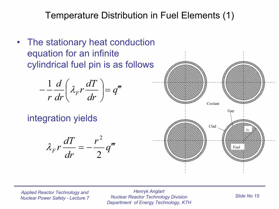
Temperature Distribution in Fuel Elements (1)
• The stationary heat conduction equation for an infinite cylindrical fuel pin is as follows
integration yields
Coolant
Clad
Gap
Fuel
rF
qdrdTr
drd
r F ′′′=− λ1
qrdrdTrF ′′′−=
2
2
λ
Henryk AnglartNuclear Reactor Technology Division
Department of Energy Technology, KTH
Applied Reactor Technology and Nuclear Power Safety - Lecture 7 Slide No 16
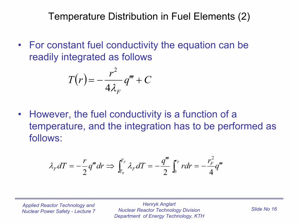
Temperature Distribution in Fuel Elements (2)
• For constant fuel conductivity the equation can be readily integrated as follows
• However, the fuel conductivity is a function of a temperature, and the integration has to be performed as follows:
( ) CqrrTF
+′′′−=λ4
2
qrrdrqdTdrqrdT F FT
T
r FFF ′′′−=
′′′−=⇒′′′−= ∫ ∫
0 0
2
422λλ
Henryk AnglartNuclear Reactor Technology Division
Department of Energy Technology, KTH
Applied Reactor Technology and Nuclear Power Safety - Lecture 7 Slide No 17
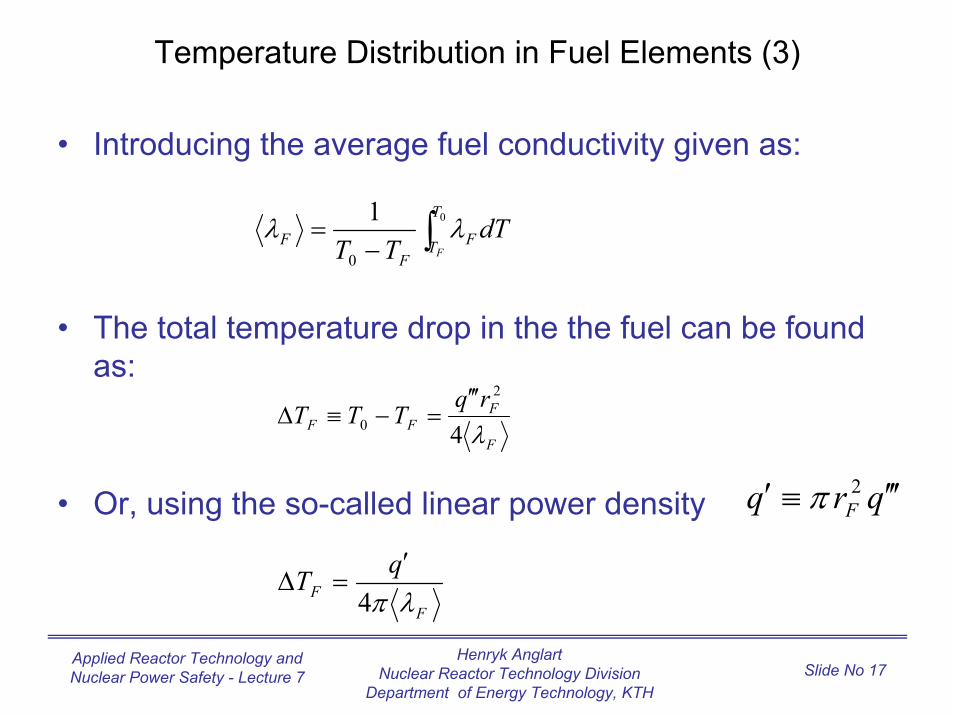
Temperature Distribution in Fuel Elements (3)
• Introducing the average fuel conductivity given as:
• The total temperature drop in the the fuel can be found as:
• Or, using the so-called linear power density
∫−= 0
0
1 T
T FF
FF
dTTT
λλ
F
FFF
rqTTT
λ4
2
0
′′′=−≡∆
qrq F ′′′≡′ 2π
FF
qTλπ4′
=∆
Henryk AnglartNuclear Reactor Technology Division
Department of Energy Technology, KTH
Applied Reactor Technology and Nuclear Power Safety - Lecture 7 Slide No 18
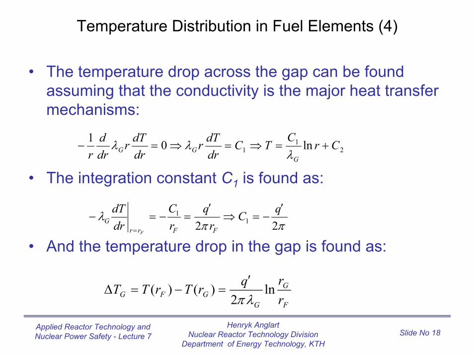
Temperature Distribution in Fuel Elements (4)
• The temperature drop across the gap can be found assuming that the conductivity is the major heat transfer mechanisms:
• The integration constant C1 is found as:
• And the temperature drop in the gap is found as:
21
1 ln01 CrC
TCdrdTr
drdTr
drd
r GGG +=⇒=⇒=− λλ
ππλ
22 11 qC
rq
rC
drdT
FFrrG
F
′−=⇒
′=−=−
=
F
G
GGFG r
rqrTrTT ln2
)()(λπ′
=−=∆
λ
Henryk AnglartNuclear Reactor Technology Division
Department of Energy Technology, KTH
Applied Reactor Technology and Nuclear Power Safety - Lecture 7 Slide No 19
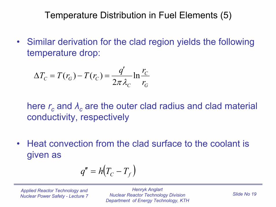
Temperature Distribution in Fuel Elements (5)
• Similar derivation for the clad region yields the following temperature drop:
here rc and λc are the outer clad radius and clad material conductivity, respectively
• Heat convection from the clad surface to the coolant is given as
G
C
CCGC r
rqrTrTT ln2
)()(λπ′
=−=∆
( )fC TThq −=′′
Henryk AnglartNuclear Reactor Technology Division
Department of Energy Technology, KTH
Applied Reactor Technology and Nuclear Power Safety - Lecture 7 Slide No 20
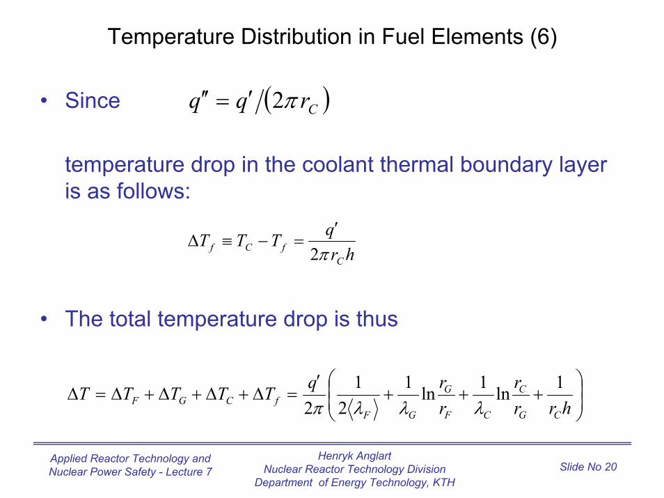
Temperature Distribution in Fuel Elements (6)
• Since
temperature drop in the coolant thermal boundary layer is as follows:
• The total temperature drop is thus
( )Crqq π2′=′′
hrqTTT
CfCf π2
′=−≡∆
+++
′=∆+∆+∆+∆=∆
hrrr
rrqTTTTT
CG
C
CF
G
GFfCGF
1ln1ln12
12 λλλπ
Henryk AnglartNuclear Reactor Technology Division
Department of Energy Technology, KTH
Applied Reactor Technology and Nuclear Power Safety - Lecture 7 Slide No 21
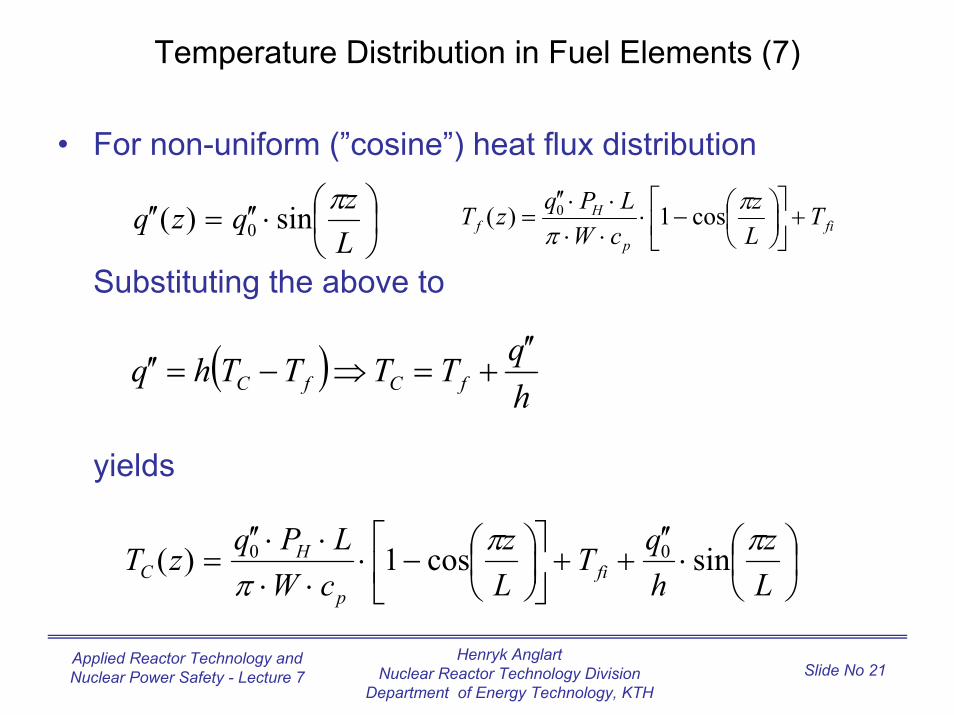
Temperature Distribution in Fuel Elements (7)
• For non-uniform (”cosine”) heat flux distribution
Substituting the above to
yields
⋅′′=′′
Lzqzq πsin)( 0 fi
p
Hf T
Lz
cWLPqzT +
−⋅
⋅⋅⋅⋅′′
=π
πcos1)( 0
( )hqTTTThq fCfC′′
+=⇒−=′′
⋅
′′++
−⋅
⋅⋅⋅⋅′′
=Lz
hqT
Lz
cWLPqzT fip
HC
πππ
sincos1)( 00
Henryk AnglartNuclear Reactor Technology Division
Department of Energy Technology, KTH
Applied Reactor Technology and Nuclear Power Safety - Lecture 7 Slide No 22
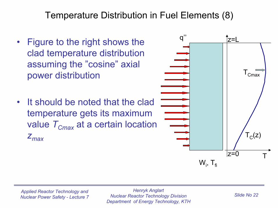
Temperature Distribution in Fuel Elements (8)
q’’ z=L
Tz=0
TC(z)
TCmax
• Figure to the right shows the clad temperature distribution assuming the ”cosine” axial power distribution
• It should be noted that the clad temperature gets its maximum value TCmax at a certain location zmax
Wi, Tfi
Henryk AnglartNuclear Reactor Technology Division
Department of Energy Technology, KTH
Applied Reactor Technology and Nuclear Power Safety - Lecture 7 Slide No 23
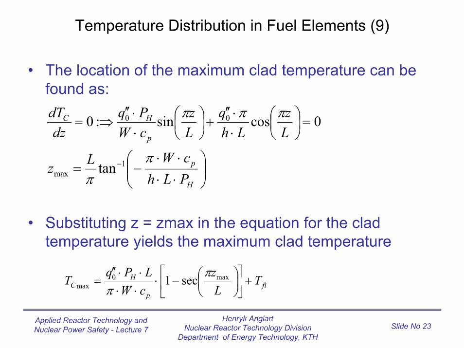
Temperature Distribution in Fuel Elements (9)
• The location of the maximum clad temperature can be found as:
• Substituting z = zmax in the equation for the clad temperature yields the maximum clad temperature
⋅⋅⋅⋅
−=
=
⋅⋅′′
+
⋅⋅′′
⇒=
−
H
p
p
HC
PLhcWLz
Lz
Lhq
Lz
cWPq
dzdT
ππ
πππ
1max
00
tan
0cossin:0
fip
HC T
Lz
cWLPqT +
−⋅
⋅⋅⋅⋅′′
= max0max sec1 π
π
Henryk AnglartNuclear Reactor Technology Division
Department of Energy Technology, KTH
Applied Reactor Technology and Nuclear Power Safety - Lecture 7 Slide No 24
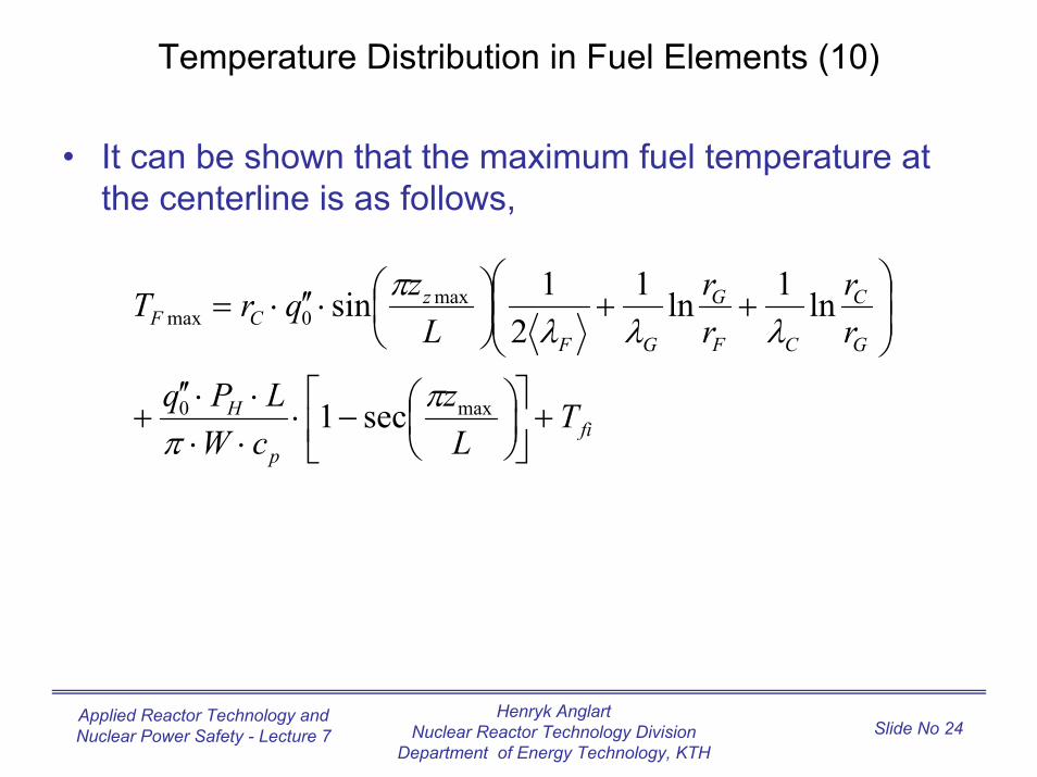
Temperature Distribution in Fuel Elements (10)
• It can be shown that the maximum fuel temperature at the centerline is as follows,
fip
H
G
C
CF
G
GF
zCF
TL
zcWLPq
rr
rr
LzqrT
+
−⋅
⋅⋅⋅⋅′′
+
++
⋅′′⋅=
max0
max0max
sec1
ln1ln12
1sin
ππ
λλλπ
Henryk AnglartNuclear Reactor Technology Division
Department of Energy Technology, KTH
Applied Reactor Technology and Nuclear Power Safety - Lecture 7 Slide No 25
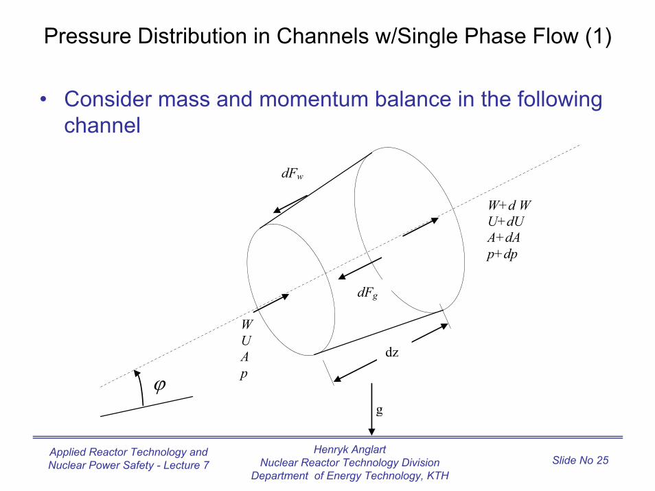
Pressure Distribution in Channels w/Single Phase Flow (1)
• Consider mass and momentum balance in the following channel
dFw
W U A p
W+d W U+dU A+dA p+dp
ϕ
dz
g
dFg
Henryk AnglartNuclear Reactor Technology Division
Department of Energy Technology, KTH
Applied Reactor Technology and Nuclear Power Safety - Lecture 7 Slide No 26
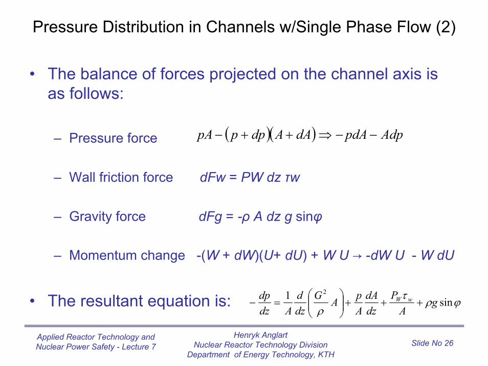
Pressure Distribution in Channels w/Single Phase Flow (2)
• The balance of forces projected on the channel axis is as follows:
– Pressure force
– Wall friction force dFw = PW dz τw
– Gravity force dFg = -ρ A dz g sinφ
– Momentum change -(W + dW)(U+ dU) + W U → -dW U - W dU
• The resultant equation is:
( )( ) AdppdAdAAdpppA −−⇒++−
ϕρτρ
sin1 2
gA
PdzdA
ApAG
dzd
Adzdp wW +++
=−
Henryk AnglartNuclear Reactor Technology Division
Department of Energy Technology, KTH
Applied Reactor Technology and Nuclear Power Safety - Lecture 7 Slide No 27
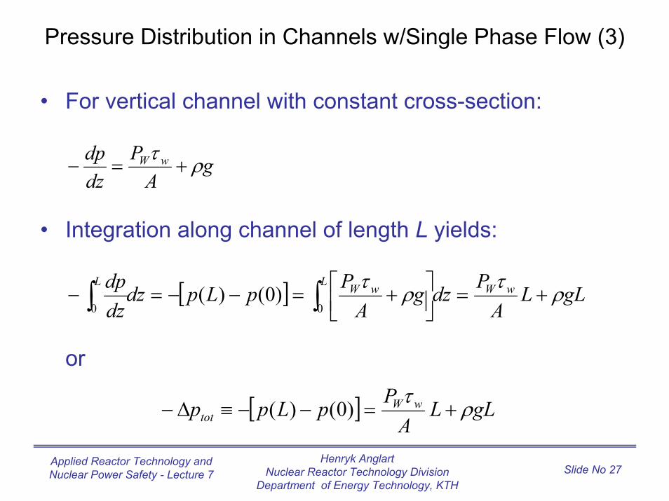
Pressure Distribution in Channels w/Single Phase Flow (3)
• For vertical channel with constant cross-section:
• Integration along channel of length L yields:
or
gA
Pdzdp wW ρτ
+=−
[ ] gLLA
PdzgA
PpLpdzdzdp wWL wWL
ρτρτ+=
+=−−=− ∫∫ 00
)0()(
[ ] gLLA
PpLpp wWtot ρτ
+=−−≡∆− )0()(

Henryk AnglartNuclear Reactor Technology Division
Department of Energy Technology, KTH
Applied Reactor Technology and Nuclear Power Safety - Lecture 7 Slide No 28
Pressure Distribution in Channels w/Single Phase Flow (4)
• In a straight channel with constant cross-section area the only irreversible pressure loss is caused by friction:
thus
LA
Pp wWfric
τ=∆−
ρτ
2
2GC fw ≡
ρ2
2GA
PCdzdp W
ffric
⋅=
−
ρ2
2GA
LPCp Wffric ⋅=∆−
where
Henryk AnglartNuclear Reactor Technology Division
Department of Energy Technology, KTH
Applied Reactor Technology and Nuclear Power Safety - Lecture 7 Slide No 29
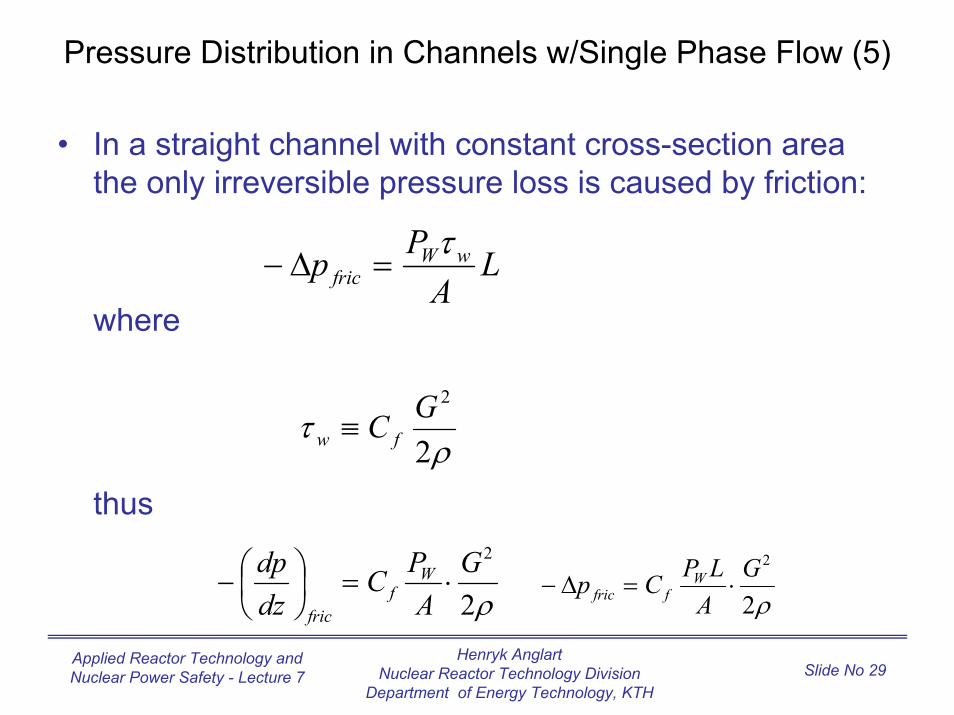
Pressure Distribution in Channels w/Single Phase Flow (5)
• In a straight channel with constant cross-section area the only irreversible pressure loss is caused by friction:
thus
LA
Pp wWfric
τ=∆−
ρτ
2
2GC fw ≡
ρ2
2GA
PCdzdp W
ffric
⋅=
−
ρ2
2GA
LPCp Wffric ⋅=∆−
where
Henryk AnglartNuclear Reactor Technology Division
Department of Energy Technology, KTH
Applied Reactor Technology and Nuclear Power Safety - Lecture 7 Slide No 30
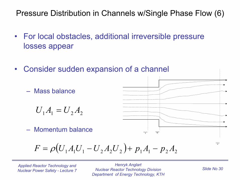
Pressure Distribution in Channels w/Single Phase Flow (6)
• For local obstacles, additional irreversible pressure losses appear
• Consider sudden expansion of a channel
– Mass balance
– Momentum balance”1”
”2”
”0”
2211 AUAU =
( ) 2211222111 ApApUAUUAUF −+−= ρ
Henryk AnglartNuclear Reactor Technology Division
Department of Energy Technology, KTH
Applied Reactor Technology and Nuclear Power Safety - Lecture 7 Slide No 31
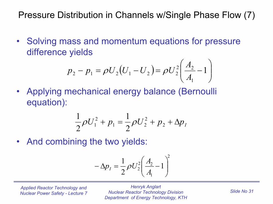
Pressure Distribution in Channels w/Single Phase Flow (7)
• Solving mass and momentum equations for pressure difference yields
equation):
• And combining the two yields:
( )
−=−=− 1
1
22221212 A
AUUUUpp ρρ
IppUpU ∆++=+ 2221
21 2
121 ρρ
2
1
222 1
21
−=∆−
AAUpI ρ
• Applying mechanical energy balance (Bernoulli
Henryk AnglartNuclear Reactor Technology Division
Department of Energy Technology, KTH
Applied Reactor Technology and Nuclear Power Safety - Lecture 7 Slide No 32
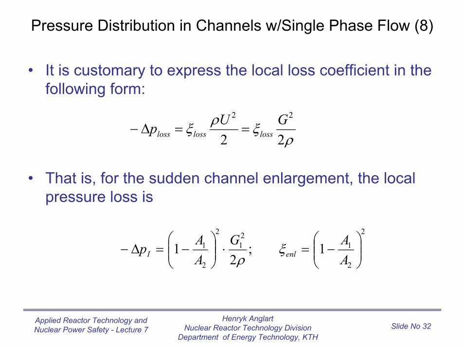
Pressure Distribution in Channels w/Single Phase Flow (8)
• It is customary to express the local loss coefficient in the following form:
• That is, for the sudden channel enlargement, the local pressure loss is
ρξρξ
22
22 GUp losslossloss ==∆−
2
2
121
2
2
1 1;2
1
−=⋅
−=∆−
AAG
AAp enlI ξ
ρ
Henryk AnglartNuclear Reactor Technology Division
Department of Energy Technology, KTH
Applied Reactor Technology and Nuclear Power Safety - Lecture 7 Slide No 33
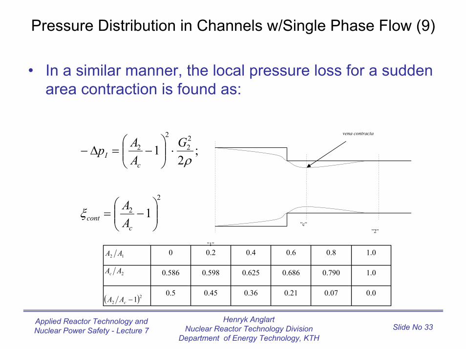
Pressure Distribution in Channels w/Single Phase Flow (9)
• In a similar manner, the local pressure loss for a sudden area contraction is found as:
”1”
”2””c”
vena contracta
2
2
22
2
2
1
;2
1
−=
⋅
−=∆−
ccont
I
AA
GAAp
ξ
ρ
12 AA
2AAc
( )22 1−cAA
0.00.070.210.360.450.5
1.00.7900.6860.6250.5980.586
1.00.80.60.40.20
c
Henryk AnglartNuclear Reactor Technology Division
Department of Energy Technology, KTH
Applied Reactor Technology and Nuclear Power Safety - Lecture 7 Slide No 34
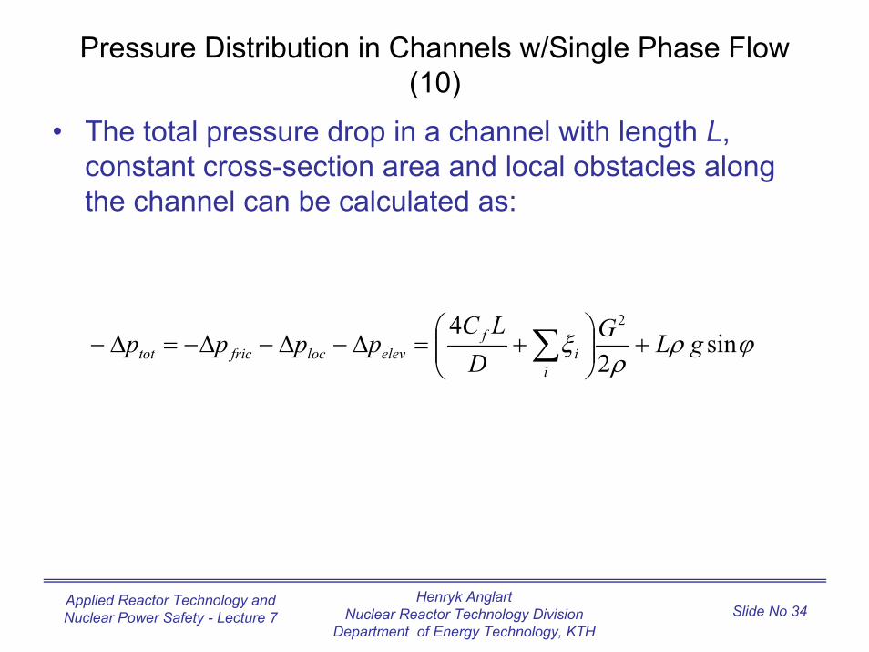
Pressure Distribution in Channels w/Single Phase Flow (10)
• The total pressure drop in a channel with length L, constant cross-section area and local obstacles along the channel can be calculated as:
ϕρρ
ξ sin2
4 2
gLGD
LCpppp
ii
felevlocfrictot +
+=∆−∆−∆−=∆− ∑
Henryk AnglartNuclear Reactor Technology Division
Department of Energy Technology, KTH
Applied Reactor Technology and Nuclear Power Safety - Lecture 7 Slide No 35
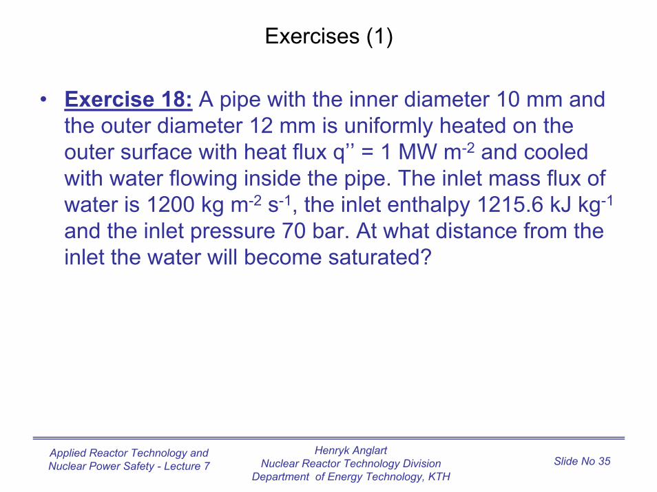
Exercises (1)
• Exercise 18: A pipe with the inner diameter 10 mm and the outer diameter 12 mm is uniformly heated on the
-2
with water flowing inside the pipe. The inlet mass flux of water is 1200 kg m-2 s-1, the inlet enthalpy 1215.6 kJ kg-1
inlet the water will become saturated?
outer surface with heat flux q’’ = 1 MW m and cooled
and the inlet pressure 70 bar. At what distance from the
Henryk AnglartNuclear Reactor Technology Division
Department of Energy Technology, KTH
Applied Reactor Technology and Nuclear Power Safety - Lecture 7 Slide No 36
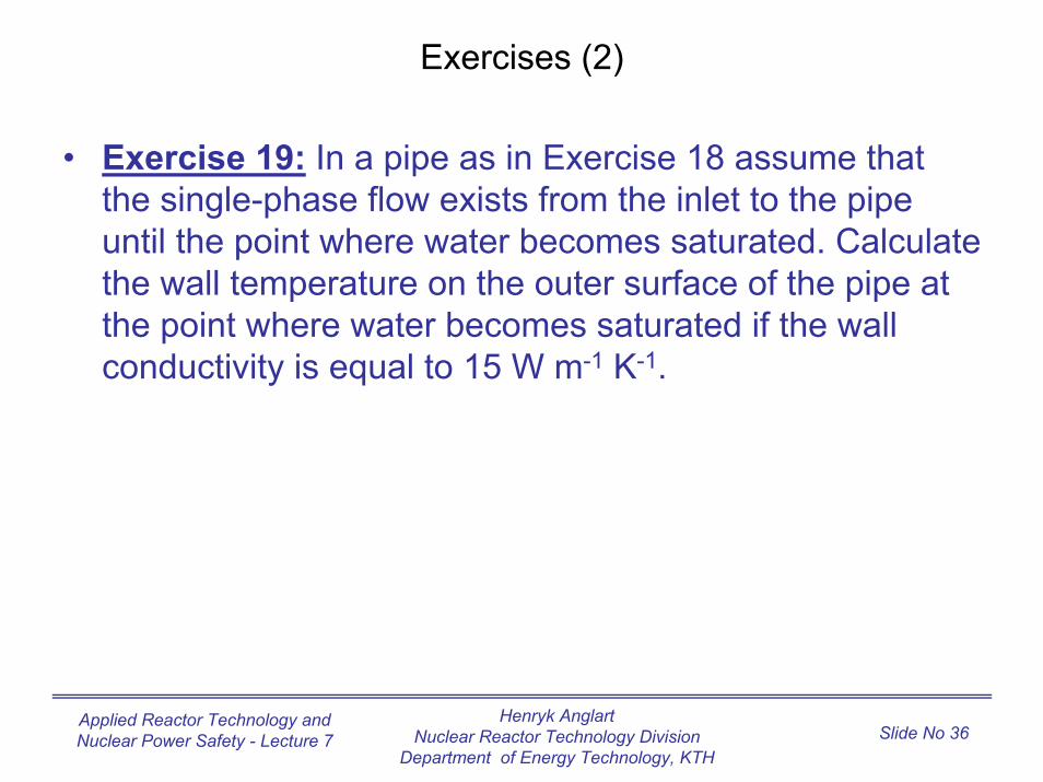
Exercises (2)
• Exercise 19: In a pipe as in Exercise 18 assume that the single-phase flow exists from the inlet to the pipe
the wall temperature on the outer surface of the pipe at the point where water becomes saturated if the wall
-1 -1
until the point where water becomes saturated. Calculate
conductivity is equal to 15 W m K .
Henryk AnglartNuclear Reactor Technology Division
Department of Energy Technology, KTH
Applied Reactor Technology and Nuclear Power Safety - Lecture 7 Slide No 37
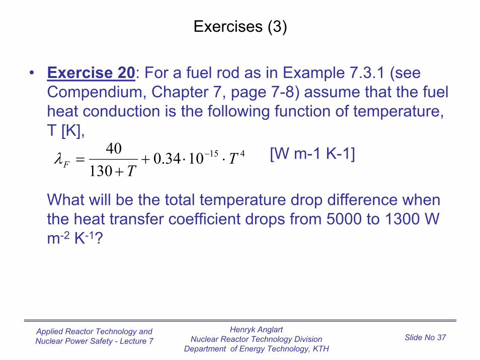
Exercises (3)
• Exercise 20: For a fuel rod as in Example 7.3.1 (see Compendium, Chapter 7, page 7-8) assume that the fuel
T [K],[W m-1 K-1]
What will be the total temperature drop difference when the heat transfer coefficient drops from 5000 to 1300 W m-2 K-1?
4151034.0130
40 TF ⋅⋅+= −λ
heat conduction is the following function of temperature,
T+
Henryk AnglartNuclear Reactor Technology Division
Department of Energy Technology, KTH
Applied Reactor Technology and Nuclear Power Safety - Lecture 7 Slide No 38
Exercises (4)
• Exercise 21: Water flows in a horizontal pipe with a sudden expansion. Calculate the total pressure drop
diameter suddenly increases from A1 = 10 cm2 to A2 = 12 cm2. Assume flow of water in direction from smaller to
740 kg m-3.
(reversible and irreversible) in a place where the pipe
larger flow area with mass flow rate 1 kg/s and density
Henryk AnglartNuclear Reactor Technology Division
Department of Energy Technology, KTH
Applied Reactor Technology and Nuclear Power Safety - Lecture 7 Slide No 39
Exercises (5)
• Exercise 22: Solve the problem as in Exercise 21, but assume that the water flows in a direction from the larger
Explain why the pressure drops in Exercises 21 and 22 are different.
to the smaller cross-section area (sudden contraction).