Embed Size (px)
Citation preview
1 3
Surg Radiol Anat (2014) 36:1063–1069DOI 10.1007/s00276-014-1274-x
ANATOMIC BASES OF MEDICAL, RADIOLOGICAL AND SURGICAL TECHNIQUES
Applied anatomy of a minimally invasive muscle‑splitting approach to posterior C1–C2 fusion: an anatomical feasibility study
Gergely Bodon · Lajos Patonay · Gabor Baksa · Claes Olerud
Received: 29 August 2013 / Accepted: 13 February 2014 / Published online: 2 March 2014 © Springer-Verlag France 2014
cadavers. We placed mini polyaxial screws in C1 lateral mass and C2 pars interarticularis in four cadavers accord-ing to the technique described by Harms and Melcher.Conclusions Using this approach, it was possible to reach the posterior aspect of C1 and C2; the relevant anatomy needed to perform a C1–C2 fusion could be well visualized.
Keywords Upper cervical spine · Atlantoaxial stabilization · Minimally invasive spine surgery
Introduction
Complex and variable anatomy of the upper cervical spine makes atlantoaxial fusion a challenging technique. Atlan-toaxial instability could be caused by various pathologies including congenital anomaly, trauma, tumor, degenerative disease, infection or rheumatoid arthritis.
Posterior atlantoaxial fusion was first done more than one hundred years ago by Mixter and Osgood in 1910 [14], using a braided silk band. In 1939, Gallie reported his tech-nique using posterior wiring [3] which was later modified by Brooks in 1978 [1]. The latter two techniques yielded to relatively high failure rates [2, 13]. In 1987 Magerl and Seeman introduced their technique using a transarticular screw fixation resulting in significantly better stability [12]. Goel reported a modified plate and screw method to fuse C1 and C2 in 1994 [5] and Harms and Melcher published their technique of C1–C2 fusion using a polyaxial screw and rod construct in 2001 [8].
The standard posterior C1–C2 fusion is related with a significant iatrogenic soft tissue injury through subpe-riosteal muscle dissection from occiput to C3–C4 and retraction, resulting in significant postoperative pain and
Abstract Purpose To describe the applied anatomy of a minimally invasive muscle-splitting approach used to reach the poste-rior aspect of the C1–C2 complex.Summary of background data Atlantoaxial fusion using a midline posterior approach and polyaxial screw and rod system is widely used. Although minimally invasive vari-ations of this technique have been recently reported, the complex applied anatomy of these approaches has not been described. The C1–C2 complex represents an unique chal-lenge because of its bony and vascular anatomy. In this study, the applied anatomy and feasibility of this technique are examined on cadavers.Methods The microsurgical anatomy of the upper cervi-cal spine is examined on a formalin-fixed and on a fresh cadaver. The muscle-splitting approach is performed on 12 fresh cadavers using this technique.Results The minimally invasive muscle-splitting approach is described in detail. Relevant anatomy and bony land-marks that aid screw placement in C1 and C2 could be well visualized. Using this approach, we were able to reach the lateral mass of the atlas and the inferior articular pro-cess and pars interarticularis of the axis in all of the nine
G. Bodon (*) Department of Orthopaedic Surgery, Klinikum Esslingen, Hirschlandstrasse 97, 73730 Esslingen a.N., Germanye-mail: [email protected]
L. Patonay · G. Baksa Department of Anatomy, Histology and Embryology, Laboratory for Applied and Clinical Anatomy, Semmelweis University Budapest, Budapest, Hungary
C. Olerud Department of Orthopedics, Uppsala University Hospital, 751 85 Uppsala, Sweden
1064 Surg Radiol Anat (2014) 36:1063–1069
1 3
impaired muscle function. This significant soft tissue dam-age to the upper cervical spine leads to a disruption of the posterior ligamentous tension band, resulting in altered biomechanics [22]. Open posterior approaches to the cervi-cal spine may cause persistent postoperative pain, muscle spasm and dysfunction in 18–60 % of the patients and also increase the risk of postoperative sagittal plane deformity and adjacent segment disease [15].
The application of minimally invasive surgical tech-niques to perform Harms C1–C2 fusion using polyaxial screws is the newest development of this technique. Up to now, different techniques have been published: a muscle-preserving technique using intermuscular planes described by Shiraishi [20] and a muscle-dilating approach using expandable tubular retractors by Joseffer [11], Holly [9] and Taghva [21]. We describe the applied anatomy of a minimally invasive muscle-splitting approach to the upper cervical spine.
The goal of minimally invasive surgery is to minimize approach-related morbidity. Positive effects of minimally invasive surgery through preservation of muscles and sta-bilizing ligamentous structures, limiting retraction, devas-cularization and denervation of muscles, decreasing intra-operative blood loss, postoperative pain and shortening hospital stay have been demonstrated [4, 7, 11, 19].
Materials and methods
Study design
We used one formalin-fixed and one fresh specimen to examine the microsurgical anatomy of the posterior upper cervical spine. The anatomic dissection was carried out
using lupe magnification and a detailed photo documenta-tion was carried out.
A total of 12 bilateral surgical approaches were per-formed in 12 fresh cadavers. The cadaveric dissections were done with the cadaver in the prone position. The sur-gical level was confirmed using a portable C-arm. In four cadavers, we instrumented the C1 lateral mass and C2 pars interarticularis using 3.5-mm polyaxial screws.
During the approach, we used classical surgical prepara-tion, standard retractors and hand-held Langenbecks.
Our goal was to describe the applied anatomy and to examine the feasibility of this approach, namely if it is pos-sible to reach the screw entry points and those landmarks that aid in the placement of the C1 lateral mass and C2 pars interarticularis screws using this minimally invasive mus-cle-splitting approach.
Surgical approach
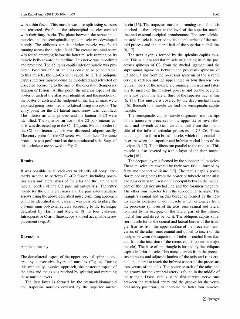
The cadaver was positioned prone, and anteroposterior views were obtained to identify the C1–C2 articulation and articular gap using a portable C-arm. The C-arm was rotated 10° lateral to one side and the planned skin inci-sion was marked on the skin above the entry point of the C1 lateral mass screw and the C2 pars interarticularis screw down to the C2–C3 joint (about 3–4 cm from the midline) (Fig. 1).
The skin and the nuchal fascia were opened. The skin incision was 3.5 cm long. Sometimes lateral edge of the trapezius muscle was seen, and retracted medially. Below the nuchal fascia, we found the fibers of the splenius capi-tis muscle running cranial and lateral. The muscle was split using scissors and retracted. Below we found the fibers of the semispinalis capitis muscle running cranial covered
Fig. 1 Picture a shows the posterior aspect of the upper cervi-cal spine and the occiput on a macerated bone specimen. Palpable landmarks in the midline are the external occipital protuberance (white asterisk) and the spinous process of the axis (black asterisk).
Arrows point at the tip of the transverse processes of the atlas. Picture b shows the left side of the same specimen, 10° rotated to the left. White square indicates the surgical “window”; the asterisks indicate the entry points of the screws
1065Surg Radiol Anat (2014) 36:1063–1069
1 3
with a thin fascia. This muscle was also split using scissors and retracted. We found the suboccipital muscles covered with their fatty fascia. The plane between the suboccipital muscles and the semispinalis capitis muscle was developed bluntly. The obliquus capitis inferior muscle was found running across the surgical field. The greater occipital nerve was found emerging below the latter muscle running on its muscle belly toward the midline. This nerve was mobilized and protected. The obliquus capitis inferior muscle was pre-pared. Posterior arch of the atlas could be palpated cranial to this muscle, the C2–C3 joint caudal to it. The obliquus capitis inferior muscle could be mobilized and retracted or dissected according to the aim of the operation (temporary fixation or fusion). At this point, the inferior aspect of the posterior arch of the atlas was identified and the junction of the posterior arch and the midpoint of the lateral mass were exposed going from medial to lateral using dissectors. The entry point for the C1 lateral mass screw was identified. The inferior articular process and the lamina of C2 were identified. The superior surface of the C2 pars interarticu-laris was dissected up to the C1–C2 joint. Medial border of the C2 pars interarticularis was dissected subperiosteally. The entry point for the C2 screw was identified. The same procedure was performed on the contralateral side. Steps of this technique are showed in Fig. 2.
Results
It was possible in all cadavers to identify all bony land-marks needed to perform C1–C2 fusion, including poste-rior arch and lateral mass of the atlas and the lamina and medial border of the C2 pars interarticularis. The entry points for the C1 lateral mass and C2 pars interarticularis screws using the above described muscle-splitting approach could be identified in all cases. It was possible to place the 3.5-mm mini polyaxial screws according to the technique described by Harms and Melcher [8] in four cadavers. Intraoperative C-arm fluoroscopy showed acceptable screw placement (Fig. 3).
Discussion
Applied anatomy
The dorsolateral aspect of the upper cervical spine is cov-ered by consecutive layers of muscles (Fig. 4). During this minimally invasive approach, the posterior aspect of the atlas and the axis is reached by splitting and retracting these muscle layers.
The first layer is formed by the sternocleidomastoid and trapezius muscles covered by the superior nuchal
fascia [16]. The trapezius muscle is running cranial and is attached to the occiput at the level of the superior nuchal line and external occipital protuberance. The sternocleido-mastoid muscle is inserted to the lateral surface of the mas-toid process and the lateral half of the superior nuchal line [6, 17].
The next layer is formed by the splenius capitis mus-cle. This is a thin and flat muscle originating from the pro-cessus spinosus of C3, from the nuchal ligament and the supraspinal ligaments between the processus spinosus of C3 and C7 and from the processus spinosus of the seventh cervical vertebra and the upper three or four thoracic ver-tebras. Fibers of the muscle are running upwards and later-ally to insert on the mastoid process and on the occipital bone just below the lateral third of the superior nuchal line [6, 17]. This muscle is covered by the deep nuchal fascia [16]. Beneath this muscle we find the semispinalis capitis muscle.
The semispinalis capitis muscle originates from the tips of the transverse processes of the upper six or seven tho-racic and seventh cervical vertebra, and from the lateral side of the inferior articular processes of C3–C6. These tendons join to form a broad muscle, which runs cranial to insert between the superior and inferior nuchal lines of the occiput [6, 17]. Their fibers run parallel to the midline. This muscle is also covered by a thin layer of the deep nuchal fascia [16].
The deepest layer is formed by the suboccipital muscles. These muscles are covered by their own fascia, formed by fatty and connective tissue [17]. The rectus capitis poste-rior minor originates from the posterior tubercle of the atlas and runs cranial to insert on the occiput between the medial part of the inferior nuchal line and the foramen magnum. The other four muscles form the suboccipital triangle. The triangle’s cranial and medial border is formed by the rec-tus capitis posterior major muscle which originates from the processus spinosus of the axis, runs cranial and lateral to insert to the occiput, on the lateral part of the inferior nuchal line and direct below it. The obliquus capitis supe-rior muscle forms the cranial and lateral border of the trian-gle. It arises from the upper surface of the processus trans-versus of the atlas, runs cranial and dorsal to insert on the occiput between the superior and inferior nuchal lines (lat-eral from the insertion of the rectus capitis posterior major muscle). The base of the triangle is formed by the obliquus capitis inferior muscle. This muscle arises from the proces-sus spinosus and adjacent lamina of the axis and runs cra-nial and lateral to reach the inferior aspect of the processus transversus of the atlas. The posterior arch of the atlas and the groove for the vertebral artery is found in the middle of the triangle. Dorsal ramus of the first cervical nerve runs between the vertebral artery and the groove for the verte-bral artery posteriorly to innervate the latter four muscles.
1066 Surg Radiol Anat (2014) 36:1063–1069
1 3
The lateral half of the obliquus capitis inferior muscle partly covers the posterior aspect of the posterior arch of the atlas. The atlantic (horizontal) part of the V3 segment of the vertebral artery lies cranial to the lateral half of the obliquus capitis inferior muscle. This muscle also cov-ers the C2 ganglion, which is found posterior to the lateral atlantoaxial joint. The C2–C3 joint lies below the middle
of the obliquus capitis inferior muscle. The vertical part of the V3 segment of the vertebral artery exits the transverse foramen of the axis and runs cranially to enter the trans-verse foramen of the atlas. This vertical part of the verte-bral artery is also partly covered by the obliquus capitis inferior muscle. The greater occipital nerve (medial branch of the dorsal ramus of the C2 nerve) emerges from below
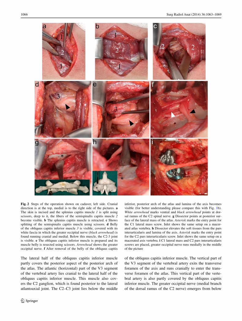
Fig. 2 Steps of the operation shown on cadaver, left side. Cranial direction is at the top, medial is to the right side of the pictures. a The skin is incised and the splenius capitis muscle 1 is split using scissors, deep to it, the fibers of the semispinalis capitis muscle 2 become visible. b The splenius capitis muscle is retracted. c Shows splitting of the semispinalis capitis muscle using scissors. d Belly of the obliquus capitis inferior muscle 3 is visible, covered with its white fascia in which the greater occipital nerve (black arrowhead) is found running cranial and medial. Below this muscle, the C2-3 joint is visible. e The obliquus capitis inferior muscle is prepared and its muscle belly is resected using scissors. Arrowhead shows the greater occipital nerve. f After removal of the belly of the obliquus capitis
inferior, posterior arch of the atlas and lamina of the axis becomes visible (for better understanding please compare this with Fig. 1b). White arrowhead marks ventral and black arrowhead points at dor-sal ramus of the C2 spinal nerve. g Dissector points at posterior sur-face of the lateral mass of the atlas. Asterisk marks the entry point for the C1 lateral mass screw. Inlet shows the same setup on a macer-ated atlas vertebra. h Dissector elevates the soft tissues from the pars interarticularis and lamina of the axis. Asterisk marks the entry point for the C2 pars interarticularis screw. Inlet shows the same setup on a macerated axis vertebra. i C1 lateral mass and C2 pars interarticularis screws are placed, greater occipital nerve runs medially in the middle of the picture
1067Surg Radiol Anat (2014) 36:1063–1069
1 3
the obliquus capitis inferior muscle and turns cranial to run toward the midline to perforate the semispinalis capitis muscle [6, 17]. These relations are shown in Fig. 5.
Rationale for minimally invasive spine surgery
The goal of minimally invasive spine surgery is to mini-mize approach-related morbidity. Positive effects of mini-mally invasive surgery through preservation of muscles
and stabilizing ligamentous structures, limiting retraction, devascularization and denervation of muscles, decreasing intraoperative blood loss, postoperative pain and shortening hospital stay have been demonstrated [4, 7, 11, 19]. Also minimally invasive approaches for the most common pos-terior cervical procedures have been described [18–20, 23].
Using this method for C1–C2 fusion, the posterior ten-sion band and the deep extensor muscles attached to the spinous process of C2, the multifidus and semispinalis
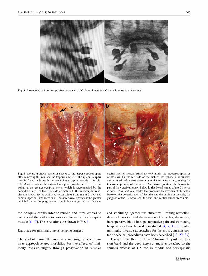
Fig. 3 Intraoperative fluoroscopy after placement of C1 lateral mass and C2 pars interarticularis screws
Fig. 4 Picture a shows posterior aspect of the upper cervical spine after removing the skin and the trapezius muscle. The splenius capitis muscle 1 and underneath the semispinalis capitis muscle 2 are vis-ible. Asterisk marks the external occipital protuberance. The arrow points at the greater occipital nerve, which is accompanied by the occipital artery. On the right side of picture b, the suboccipital mus-cles are shown: rectus capitis posterior minor 1 and major 2, obliquus capitis superior 3 and inferior 4. The black arrow points at the greater occipital nerve, looping around the inferior edge of the obliquus
capitis inferior muscle. Black asterisk marks the processus spinosus of the axis. On the left side of the picture, the suboccipital muscles are removed. White arrowhead marks the vertebral artery, exiting the transverse process of the axis. White arrow points at the horizontal part of the vertebral artery; below it, the dorsal ramus of the C1 nerve is seen. White asterisk marks the processus transversus of the atlas. Between the posterior arch of the atlas and the lamina of the axis, the ganglion of the C2 nerve and its dorsal and ventral ramus are visible
1068 Surg Radiol Anat (2014) 36:1063–1069
1 3
cervicis muscles can be left intact, which may prevent the risk of postoperative loss of lordosis [10, 22]. Muscle retraction is also reduced while the skin incision and the muscle layers are opened directly above the entry points of the screws.
Minimally invasive C1–C2 fusion
We found two minimally invasive open (not percutaneous) approaches for C1–C2 fusion using the Harms technique.
One was described by Tateru Shiraishi et al. in 2012. They used a standard midline skin incision and then used the intermuscular plane between the semispinalis cervicis and the suboccipital neck muscles (obliquus capitis infe-rior) to expose the C2 lamina and pars interarticularis, C1–C2 and C2–C3 joints. They performed six C1–C2 fusions with an average operation time of 180 min and average blood loss of 45 g [20].
The second approach, which is similar to the one shown here, was described by the group of Frempong-Boadu (Joseffer in 2005 and Holly in 2010) and Taghva in 2012.
Joseffer and Holly used a similar approach, placed the two skin incisions 2 cm from the midline, using a 2.5- or 2-cm-long skin incision, respectively. After opening the fascia, they passed the smallest dilator to the lamina of C2 and then subsequently larger dilators. They used subperi-osteal dissection to expose the C2, C3 lateral masses, sacri-ficed the C2 nerve root and exposed the inferior portion of the C1 lateral mass [9, 11].
The approach described by Taghva is very similar; he cut the skin 3.5 cm from the midline using a 3-cm-long skin incision and used standard muscle-splitting dissection and sequential dilation to dock a tubular retractor on the superior aspect of the C2 lateral mass under fluoroscopic guidance. They used monopolar cautery and dissectors to expose the C2 lateral mass and pars, C1–C2 joint and C1 lateral mass. The C2 neurovascular bundle was exposed and divided [21].
Benefits of using these techniques have been reported [9, 11, 21].
The described minimally invasive muscle-splitting approach is similar to that of reported by Joseffer, Holly and Taghva. These authors used a tubular retractor system, which was placed under fluoroscopic control.
Using our technique, the consecutive muscle lay-ers are identified, split and retracted until the level of the suboccipital muscles is reached. The key muscle of this approach, the obliquus capitis inferior muscle is then iden-tified (Fig. 5). With retraction or resection of this muscle (according to the aim of the operation: temporary fixation or fusion) bony landmarks and the entry points for the C1 lateral mass and C2 pars interarticularis screws could be visualized. This way, the posterior aspect of the lateral mass of the atlas, the C2–C3 joint, lamina and pars interar-ticularis of the axis can be reached and a posterior C1–C2 fusion or fixation using the technique described by Harms and Melcher can be performed [8].
Care should be taken not to dock the retractor or retract the obliquus capitis inferior muscle above the level of the
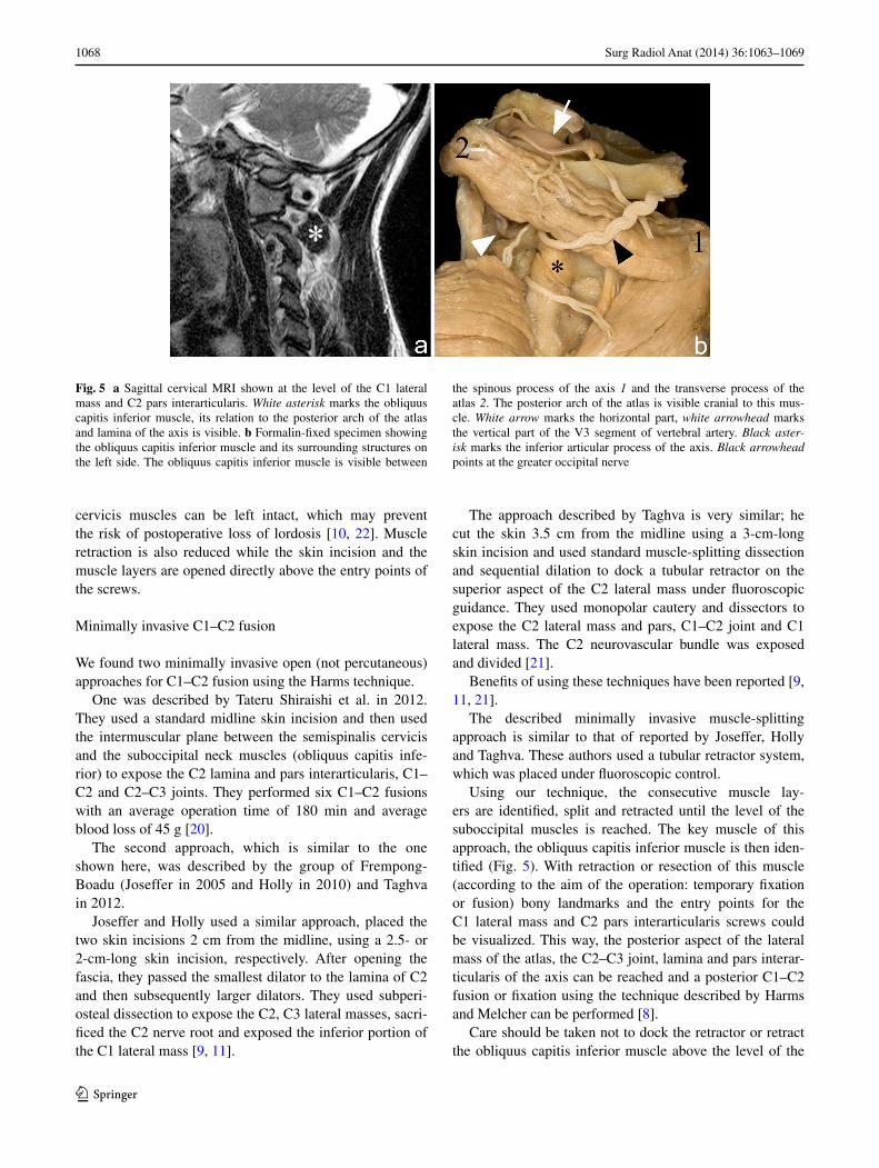
Fig. 5 a Sagittal cervical MRI shown at the level of the C1 lateral mass and C2 pars interarticularis. White asterisk marks the obliquus capitis inferior muscle, its relation to the posterior arch of the atlas and lamina of the axis is visible. b Formalin-fixed specimen showing the obliquus capitis inferior muscle and its surrounding structures on the left side. The obliquus capitis inferior muscle is visible between
the spinous process of the axis 1 and the transverse process of the atlas 2. The posterior arch of the atlas is visible cranial to this mus-cle. White arrow marks the horizontal part, white arrowhead marks the vertical part of the V3 segment of vertebral artery. Black aster-isk marks the inferior articular process of the axis. Black arrowhead points at the greater occipital nerve
1069Surg Radiol Anat (2014) 36:1063–1069
1 3
posterior arch of the atlas as the vertebral artery usually protrudes over the posterior arch and could be injured [24].
To safely perform this technique it is of paramount importance to know and recognize the muscles and ana-tomical landmarks of the region. The complex and vari-able anatomy of the posterior upper cervical spine makes the placement of expandable retractors under fluoroscopic guidance with “blind” dilatation of the muscles a danger-ous practice.
Conclusion
Minimally invasive posterior atlantoaxial fixation using a muscle-splitting approach is feasible. The relevant anatomy can be directly visualized using this technique.
Conflict of interest None.
References
1. Brooks AL, Jenkins EB (1978) Atlanto-axial arthrodesis by the wedge compression method. J Bone Joint Surg Am 60(3):279–284
2. Coyne TJ, Fehlings MG, Wallace MC, Bernstein M, Tator CH (1995) C1-C2 posterior cervical fusion: long-term evaluation of results and efficacy. Neurosurgery 37(4):688–692 (Discussion 692–3)
3. Gallie WE (1939) Fractures and dislocations of the cervical spine. Am J Surg 46:495–499
4. Gejo R, Kawaguchi Y, Kondoh T et al (2000) Magnetic resonance imaging and histologic evidence of postoperative back muscle injury in rats. Spine 25(8):941–946
5. Goel A, Laheri V (1994) Plate and screw fixation for atlanto-axial subluxation. Acta Neurochir (Wien) 129(1–2):47–53
6. Gray H, Davies DV, Davies F, Johnston TB (1958) Gray’s anat-omy, 32nd edn. Longmans Green and Co., New York, pp 579–582
7. Guiot BH, Khoo LT, Fessler RG (2002) A minimally inva-sive technique for decompression of the lumbar spine. Spine 27(4):432–438
8. Harms J, Melcher RP (2001) Posterior C1-C2 fusion with pol-yaxial screw and rod fixation. Spine 26(22):2467–2471
9. Holly LT, Isaacs RE, Frempong-Boadu AK (2010) Minimally invasive atlantoaxial fusion. Neurosurgery 66(Supplement):A193–A197
10. Iizuka H, Shimizu T, Tateno K et al (2001) Extensor muscula-ture of the cervical spine after laminoplasty: morphologic evalu-ation by coronal view of the magnetic resonance image. Spine 26(20):2220–2226
11. Joseffer SS, Post N, Cooper PR, Frempong-Boadu AK (2006) Minimally invasive atlantoaxial fixation with a polyaxial screw-rod construct: technical case report. Neurosurgery 58(Supple-ment 2):ONS–E375
12. Magerl F, Seeman PS (1987) Stable posterior fusion of the atlas and axis by transarticular screw fixation. In: Kehr P, Weidner A (eds) Cervical spine I. Springer, Heidelberg, pp 322–327
13. Melcher RP, Puttlitz CM, Kleinstueck FS, Lotz JC, Harms J, Bradford DS (2002) Biomechanical testing of posterior atlanto-axial fixation techniques. Spine 27:2435–2440
14. Mixter SJ, Osgood RB (1910) Traumatic lesions of the atlas and axis. Ann Surg 51(2):193–207
15. O’Toole J, Voyadzis JM, Gala VC (2011) Posterior minimally invasive cervical foraminotomy and laminectomy. In: Sandhu FA, Voyadzis JM, Fessler RG (eds) Decision making for minimally invasive spine surgery. Thieme, New York
16. Pernkopf E (1952) Topographische Anatomie des Menschen. III. Band Der, Hals. Urban & Schwarzenberg, Germany, pp 63–67
17. Rickenbacher J, Landolt AM, Theiler K (1982) Lanz/Wachsmuth Praktische Anatomie Rücken. Springer, Heidelberg, pp 78–98
18. Santiago P, Fessler RG (2007) Minimally invasive surgery for the management of cervical spondylosis. Neurosurgery 60:S160–S165
19. Shiraishi T, Fukuda K, Yato Y, Nakamura M, Ikegami T (2003) Results of skip laminectomy-minimum 2-year follow-up study compared with open-door laminoplasty. Spine 28(24):2667–2672
20. Shiraishi T, Kato M, Yato Y et al (2012) New techniques for exposure of posterior cervical spine through intermuscular planes and their surgical application. Spine 37(5):E286–E296
21. Taghva A, Attenello FJ, Zada G, Khalessi AA, Hsieh PC (2012) Minimally invasive posterior atlantoaxial fusion: a cadaveric and clinical feasibility study. World Neurosurg. doi:10.1016/j.wneu.2012.01.054
22. Takeshita K, Peterson ETK, Bylski-Austrow D, Crawford AH, Nakamura K (2004) The nuchal ligament restrains cervical spine flexion. Spine 29(18):E388–E393
23. Wang MY, Levi ADO (2006) Minimally invasive lateral mass screw fixation in the cervical spine: initial clinical experience with long-term follow-up. Neurosurgery 58(5):907–912 (Discus-sion 907–12)
24. Yamaguchi S, Eguchi K, Kiura Y, Takeda M, Kurisu K (2008) Posterolateral protrusion of the vertebral artery over the poste-rior arch of the atlas: quantitative anatomical study using three-dimensional computed tomography angiography. J Neurosurg Spine 9(2):167–174


![Minimally invasive non-surgical vs. surgical approach for ...dictable [12]. More recently, minimally invasive surgical therapy (MIST), modified minimally invasive surgical therapy](https://img.pdfslide.us/doc/110x75/5eddda76ad6a402d6669115c/minimally-invasive-non-surgical-vs-surgical-approach-for-dictable-12-more.jpg)