Embed Size (px)
Citation preview
www.dexteraxle.com2900 Industrial Parkway East • Elkhart, IN 46516
Fax: 574-295-8666 • Ph. 574-295-7888
www.dexteraxle.com
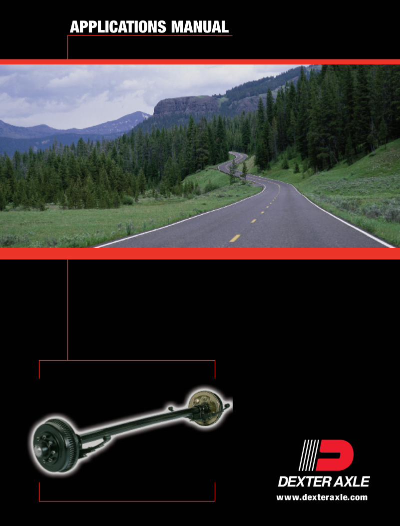
APPLICATIONS MANUAL
11/06 © Dexter Axle 2006LIT-008-00

Introduction
This information is intended as a guide for the proper specification and application of Dexter Axle running gear,associated components and accessories. We have attempted to define some of the terms commonly used in thetransportation industry as well as providing descriptions of the various systems used in building a wide variety oftrailers.
Dexter offers a full line of trailer axles that can be used in many different applications. When specifying anypre-engineered components such as axles, it is the responsibility of the trailer designer to insure compatibility with thevehicle and all of its sub-systems.
Important InformationThe information presented is meant to assist trailer manufacturers in the specification of their running gear components.Dexter Axle does not warrant that the information given constitutes an approved trailer design or application. Dynamicloading, travel requirements unique to the trailer design, unusual service conditions, trailer configurations, unequal loaddistribution, hitch or coupler arrangements and towing vehicle suspension characteristics can significantly affect theperformance of any trailer axle and/or suspension systems. It remains the responsibility of the trailer manufacturer toevaluate, specify and test their trailer/running gear combination before production and to certify it as such. While theinformation presented at the time of this writing is current, it is subject to change as designs and components evolveover time.
Disclaimer Of Warranty And Limitation Of LiabilityAll users of this product catalog acknowledge that the information presented is significantly affected by factors withinthe exclusive knowledge of the user including, among other things, service conditions, trailer configurations, loaddistributions, hitch and coupler arrangements and tow vehicle suspension characteristics, that the users haveindependently investigated these factors and have solely relied on those investigations when using this catalog, andthat it is the responsibility of the user to adequately specify, evaluate and test its trailer/running gear combinations.
DEXTER AXLE DISCLAIMS ALL WARRANTIES, WHETHER WRITTEN, ORAL OR IMPLIED, IN FACT OR IN LAW(INCLUDING ANY WARRANTY OF MERCHANTABILITY OR FITNESS FOR A PARTICULAR PURPOSE),ASSOCIATED WITH THE USE OF THE CATALOG AND WITH ANY INFORMATION PRESENTED BY THISCATALOG.
Dexter Axle shall not be liable in damages (whether compensatory, punitive, direct, indirect, special, incidental orconsequential) to any user of this catalog under contract, tort, strict liability or any other theory of liability, and any useragrees to indemnify and hold Dexter Axle harmless from any and all claims, actions or other proceedings (includingattorney fees and court costs) arising out of the use of this catalog to the extent said claims, actions or otherproceedings do not arise out of the sole and exclusive negligence of Dexter Axle.
Load RatingsThe maximum load carrying capacity of any assembly is limited to the lowest load rating of any individual componentselected. For instance, the load rating of a pair of wheels may be lower than other axle components selected. If this isthe case, the load carrying capacity of the axle assembly is reduced accordingly. As a specific example, if a pair ofwheels is rated at 1500 pounds each and is used with other components rated at 4000 pounds per axle, the maximumload capacity is limited to 3000 pounds. If two tires are rated at 1400 pounds each and are used on this assembly, themaximum load carrying capacity is limited to 2800 pounds.

Introduction . . . . . . . . . . . . . . . . . . . . . . . . . . . . . . . . . . . . . . . . . . . . . . . . . . . . . . . . . . . . . . . . .2
Definition of Terms . . . . . . . . . . . . . . . . . . . . . . . . . . . . . . . . . . . . . . . . . . . . . . . . . . . . . . . . . . .3
Trailer Design Considerations . . . . . . . . . . . . . . . . . . . . . . . . . . . . . . . . . . . . . . . . . . . . . . . . . .5
Running Gear Systems . . . . . . . . . . . . . . . . . . . . . . . . . . . . . . . . . . . . . . . . . . . . . . . . . . . . . . .9
Specifying Axles . . . . . . . . . . . . . . . . . . . . . . . . . . . . . . . . . . . . . . . . . . . . . . . . . . . . . . . . . . . .10
Other Trailer Components . . . . . . . . . . . . . . . . . . . . . . . . . . . . . . . . . . . . . . . . . . . . . . . . . . . .11
Installation Suggestions . . . . . . . . . . . . . . . . . . . . . . . . . . . . . . . . . . . . . . . . . . . . . . . . . . . . . .12
Limited Warranty . . . . . . . . . . . . . . . . . . . . . . . . . . . . . . . . . . . . . . . . . . . . . . . . . . . . . . . . . . .20
2
Table Of Contents

3
Definition Of Terms
Bump ClearanceBump is the upward displacement of a wheel centerrelative to the trailer frame (sprung mass). Clearance isthe amount of trailer frame to axle clearance necessaryto allow the axle to clear or NOT contact the trailerframe.
CamberThe angular relationship of the wheel to the roadsurface in the vertical plane. Axles are typically built witha pre-determined bend in the tube that compensates forthe expected deflection under load. Ideally, the tirefootprint will contact the road evenly across the width ofthe tread.
Center Of GravityThe point at which the entire weight of a body (vehicle)may be considered to be concentrated so that if thevehicle were supported at that point, it would remain inequilibrium. For any vehicle, both the longitudinal andtransverse center of gravity must be considered whenplacing the running gear to establish proper weightdistribution.
Ride PerformanceThe term 'ride' is a general one referring to the vehiclemotions of the sprung and unsprung masses caused bythe longitudinal road profile.
LOAD LOAD
AXLE CAMBER
GAWR - Gross Axle Weight RatingThe value specified by the vehicle manufacturer as theload carrying capacity of the axles in a system, asmeasured at the tire-ground interfaces. This includes thewheels and tires.
For example:An axle beam may be rated for 6000 lbs., the springsrated for 2500 lbs. each, the wheels rated for 3500 lbs.each, and the tires rated for 3042 lbs. each. The GAWRfor this example will be 5000 lbs., limited by the capacityof the springs.
Hitch WeightThe portion of the weight of a trailer that is carried on thetowing vehicle through the connection point.
GCWR - Gross Combined Weight RatingFor motorized vehicles, the manufacturer rates thevehicle for towing capability by defining the GrossVehicle Weight of the vehicle and combining that with theGVW of the vehicle to be towed.
HITCHWEIGHT GAWR
GCWR

GVWR - Gross Vehicle Weight RatingThe value specified by the manufacturer as the loadedweight of a single vehicle.
Dog-TrackingThe behavior a vehicle will exhibit when the body of thevehicle is skewed relative to the line of travel duringoperation. This happens when the axles have beenmounted to the frame incorrectly, that is, notperpendicular to the centerline of the vehicle. When theunit is towed, the running gear will align itself to the lineof travel but the wheel track will be offset from the trackof the tow vehicle and the body or frame will appear tobe tracking out of line.
Polar InertiaThe property that can cause a trailer to swing from sideto side during operation. One of the causes of thisphenomenon can be demonstrated with the followingexample:
A large travel trailer has the kitchen located at the rear ofthe coach. The owner has loaded supplies and personalbelongings in the rear of the unit. Side forces such ashigh winds or the bow wave from a passing vehicle maystart the swaying. As the rear end swings to the right, thetrailer pivots on its running gear and the front end swingsto the left, causing the rear end of the tow vehicle to bepulled left. If the driver overcompensates by steering left,the front of the trailer will be forced right which reversesthe direction of the trailers' rear end. Too much mass atthe ends of the trailer will accentuate the swing of thevehicle and may set up the conditions for side to sidesway that gets greater and greater as the driver attemptsto get control of the vehicle.
Toe AngleThe plane of rotation of a wheel relative to the centerlineof the vehicle.
4
Definition Of Terms
GVWR GVWR

5
Trailer Design Considerations
Trailer design is an extremely broad subject. Covering all the guidelines for the design of every towable vehicle isbeyond the scope of this manual. Instead, we have attempted to present some of the more common rules of thumbthat will, in most cases, provide a reasonable result when employed in a trailer design.
The following list describes many of the typical designs, grouped according to their intended use.
Fold Down Camper Travel Trailer Fifth Wheel Trailer
Snowmobile Trailer Enclosed Cargo Trailer Flatbed Cargo Trailer
Livestock Trailer Portable Equipment Trailer Water Craft Trailer
Single Width HomeDouble Width Half Unit
Park Model HomeModular Carrier
Recreational Vehicles
Utility Trailers
Manufactured Housing

6
Things To Consider When Designing Your Trailer• The load distribution between the hitch and the running gear is determined by placement of the axles in relation tothe center of gravity.
• The hitch weight for conventional, bumper type hitches should be 10% to 14% of the gross weight of the vehicle.The remaining 86 to 90% of the load will be carried on the running gear, so make sure that the axles, wheels andtires are properly matched and have sufficient capacity rating to support this load.
• The hitch weight for fifth wheel and gooseneck type hitches should be 15% to 20% of the gross weight of thevehicle. The remaining 80% to 85% of the load will be carried on the running gear, so make sure that the axles,wheels and tires are properly matched and have sufficient capacity rating to support this load.
• Trailer handling may be adversely affected if the load(s) are concentrated at the ends of the vehicle. This conditioncan occur even when the hitch weight is within the recommended proportion of vehicle weight. Probable causes forthis phenomenon may be excessive frame flexure and/or polar inertia.
• Polar inertia and frame flex can impose dynamic loading on the axles and suspension system which may exceedthe design loads and result in bending or fatigue failure.
• Excessive frame flexure can affect ride if the natural frequency of the vehicle's structure matches the frequency ofthe suspension. Once the flex of the frame is in phase with the suspension's vertical movement, the dynamic loadinput to the suspension will cause it to deflect more than it would under static load conditions. This greater loading ofthe suspension results in greater rebound which causes greater frame flexing. Now the larger degree of frameflexure is imposed on the suspension which causes an even greater vertical travel, and so on. If this condition exists,damage to the vehicle's structure can occur. Either the structure should be stiffened or the suspension characteristicsshould be altered to prevent this ‘in phase’ behavior.
• Uneven side to side loading of a trailer can cause dog-tracking. For double eyed leaf spring and single slipper typesprings, the front end of the spring is anchored to the vehicle frame. As the load increases, the spring arch flattens,resulting in a lengthening of the spring. Since the axle is attached near the mid-point of the spring, it will moverearward as the spring deflects. If the springs are unevenly loaded, the axle will be skewed relative to the vehiclecenterline and may cause tracking problems.
• A trailer designed to carry a load with a high center of gravity should have a wide enough axle track to prevent ordiminish the tendency for the vehicle to tip over on curves or turns with little or no banking of the road surface.
• Trailers equipped with Torflex® axles must be towed in a level attitude to insure even loading of the axles. Out-of-level towing results in higher loads being imposed on the axle at the low portion of the frame and less load on theaxle(s) at the high end. This uneven load distribution may cause excessive stress concentrations on the framestructure. Uneven loading of non-equalized suspensions can also affect the ride characteristics by altering thenatural frequency of the structure.
• The wheel and tire diameter should be large enough to provide sufficient ground clearance when used with dropspindle type axles. Insufficient clearance may result in the axle components dragging the ground in the event of a flattire.
• Axles should be spaced to allow at least one (1) inch of clearance between the tires under any loading condition.To determine the proper spacing, find the manufacturers maximum diameter for the tire and add one inch or more.The result will be the axle center to center dimension. If tire chain clearance is desired, additional clearance may benecessary.
• When designing the attachment system for Torflex® axles on aluminum trailer frames, it is important to understandthe compressive stresses imposed by the fasteners against the aluminum surfaces. Yielding in these areas can leadto loosening of the axles and could result in fatigue failure of the axle bracket and tube structure and/or the framemembers. If non-metallic materials are to be used between the mating surfaces to prevent galvanic corrosion, thedesigner must consider the stability of these materials under the high clamp loads. Extrusion of these materialsunder load may also lead to loosening of the axle attachment.
Trailer Design Considerations

7
• Spread axle mounting will lend added support to frame structures but will result in more tire wear and imposehigher stresses on the axle components and axle mountings. Increased tire wear usually results from the added sidescrubbing that occurs when negotiating sharp turns or corners.
• Wide-spread Torflex® axles will be subjected to higher stresses at the bracket/tube interfaces as a result of frameracking. Racking occurs when the vehicle travels over uneven surfaces and the loads imposed at each wheel aresubstantially different. If the torsional stiffness of the vehicle structure is relatively low, the areas where the crossmembers are joined to the main frame rails and the axle bracket/tube welds must withstand the twisting that occursin these critical regions. Excessive flexing may result in fatigue failures. To reduce the potential for problems due toracking, position the axles closer together.
• Torflex® axles should not be used in situations requiring more than two axles. These axles are non-equalized andmay experience momentary overload when traversing uneven operating surfaces such as driveway entries or speedbumps. Torflex® axles can take this momentary overload in a tandem set, however it is not reasonable to expect oneaxle to carry the load of three or more axles even in a momentary situation.
• Torflex® axle ride performance is at its best when the torsion arm is at or nearest to horizontal when the vehicle isat its rated load. This is due to the geometric relationship of the arm to the direction of loading. Torsion armsoperating above the horizontal tend to exhibit a stiffer ride. As an example, for a 3000 lb. wheel load actingperpendicular to a 6" long arm, the torque input to the suspension system is 18,000 inch pounds. For the samewheel load imposed on a 6" long arm at 45 degrees, the torque input to the suspension drops to 12,727 inch pounds.(Torque = 6(.707) x 3000, since the sine of 45 is .707).
• Axle capacity will be reduced by at least 50% when used without a suspension system (axles or stubs attacheddirectly to vehicle frame). This is NOT a recommended configuration as it transfers load directly to the frame railsand is a very harsh ride.
• Oil lubrication systems for wheel bearings should not be used in applications in cases where the vehicle will bestationary for long periods of time. The oil will drain down to the bottom of the cavity and leave the exposed parts ofthe bearings subject to corrosion.
• Dual wheels cannot be used as singles unless they are used on hubs that have been specifically designed for thatapplication. The large offset of a dual wheel shifts the load line too far from the hub face or intended load line of mosthubs. This condition will result in a serious degradation of the bearing life.
• Dexter recommends that all axles be equipped with brakes. For trailers used in commerce, the trailer axle(s) mustbe equipped with brakes unless the GAWR of the trailer axle is less than 3000 pounds and the hitch load imposedon the towing vehicle does not exceed 40% of the towing vehicles GVWR. For other details concerning commercialapplications, refer to the Federal Motor Carrier Safety Regulations published by the U.S. Department ofTransportation.
Trailer Design Considerations

8
Determining Dimensional Requirements
Trailer Design Considerations
Center of Axle Set
Center of Gravity
A
B
Note: “Center of Axle” on a Torflex® axle is defined as the center of spindle.
1. Measure the distance from the center of the hitch to the center of gravity (dim. A).2. Divide this value by the percentage of the load to be carried by the running gear.3. The result will be the distance from the center of the hitch back to the center of the axle set (dim. B).
Brake RequirementsCommercial trailers must comply with the requirements of the Federal Motor Carrier Safety Regulations asprescribed by the U.S. Department of Transportation which calls for brakes on each wheel for most applications.Consult the regulations that pertain to the type of trailer being built.
The recommended practice for any trailer design would be to use brakes on all axles. The use of trailer brakes canhelp prolong the life of the tow vehicle brakes as well as provide for safer operation.
Wheels And TiresThe wheels and tires should be matched in capacity to the axle whenever possible. The Gross Axle Weight Rating ofthe running gear will be based on the lowest rated component.
Tires are designed to be mounted on specific rim sizes and contours as defined by "The Tire and Rim Association".Mismatching of these vital components is dangerous and can result in serious injuries, catastrophic failure or poorperformance and reduced service life.
Tires of greater capacity should never be mounted on wheels of a lower capacity since most end-users will inflateand load them to the rating embossed in the tire. This practice can result in dangerous failure of the wheel whichmay lead to an accident. Wheels must also be matched to the particular hub and mounting system being used.Wheels are designed to be either hub piloted or stud piloted.
Hub piloted wheels have the center hole machined to a close tolerance and are intended to mate with a hub havinga properly sized pilot.
The bolt holes will be bored or stamped straight through the center disc which is designed to be fastened with eitherflanged nuts or a clamp ring using cone nuts.
Stud piloted wheels have a center hole which provides clearance to the hub nose. The bolt holes feature a taperedseat designed for clamping with properly matched cone nuts. The cone angle of the nut MUST match the cone anglearound the bolt hole. Failure to properly match these components will result in catastrophic wheel loss.

9
Axle TypesTorflex® - The Torflex® axle is designed as acompletely self-contained axle and suspension system.This trailing arm type torsion axle employs natural rubbercords supporting heat treated inner bars of solid,medium carbon steel. Press-fitted and welded to theends of these independently floating bars are the highstrength steel torsion arm/spindle assemblies. Thesearms can be specified to a range of starting angles,which allow the designer to tailor the running height ofthe vehicle.
Leaf spring - These axles utilize high strength steelspindles welded to high strength tubing to form an axlebeam. The spindles are usually available in either astraight or drop design to help designers establish thedesired frame height or ground clearance. Leaf springsare attached to the axle using u-bolts and can bepositioned either under or over the tube. Use undermounted springs (underslung) to lower the frame heightand over mounted springs (overslung) to raise the frame.The designer can chose stamped steel hangers ofvarying heights to allow additional control of the vehicleheight.
Axle Attachment SystemsHangers and attaching parts - Most hangers arechannel shaped steel stampings, designed to be weldedto the underside of the frame rails to provide theattaching points for the leaf springs and their associatedparts. The attaching parts are normally provided in kits,which contain all the necessary hardware to properlyinstall the running gear. In the case of multiple axleinstallations, devices called equalizers are often used tohelp transfer load from one axle to the other(s) as thevehicle travels over uneven terrain. Not all combinationsof equalizers and hangers are suitable. If the equalizerhangers are too short, the spring eye may contact theframe during articulation of the suspension and mayresult in overloading of the spring.
Running Gear Systems
Brake TypesElectric and hydraulic, shoe/drum - Electric brakes aresimilar to the hydraulic drum brakes used on automobilesand trucks. While those brakes are actuated by hydraulicpressure, generated by the master cylinder to expandthe wheel cylinder, electric brakes function by the actionof an electromagnet inside the brake drum. When avoltage is sent by the brake controller to theelectromagnets, they are attracted to the rotatingarmature surface of the drum. The sliding friction of themagnets against the armature surface actuates a leverwhich in turn expands the brake shoes out against thedrum surface. This is much like the action that occurswithin a hydraulic brake when the wheel cylinderexpands. The braking effort is modulated by varying theamount of voltage supplied to the magnets whereas,hydraulic brakes are controlled by the output pressure ofthe master cylinder.
Primary Shoe
Actuating Lever
MagnetAdjuster Spring
Adjuster
Shoe HoldDown Spring
Secondary Shoe
Retractor Spring
Front of Brake
Anchor Post
RetractorSprings
Backing Plate
Secondary Shoe
Adjuster SpringAdjuster Assembly
Primary Shoe
Hold Down Spring
Actuating Pin
Hydraulic Wheel Cylinder

10
Air brakes, drum type - This type of brake operates byrotating an 's' shaped cam between the non-anchoredends of the brake shoes, causing them to expandoutward and exert pressure against the drum surface.The rotation of the cam shaft is accomplished using anair cylinder called a brake chamber, acting on a lever,(the slack adjuster) which also provides a means ofadjusting the clearance between the brake shoes andthe drum surface. This adjustment compensates for wearand can be done manually or automatically.
Running Gear Systems
Disc brakes - Disc brakes employ a component called arotor, which takes the place of the drum in a shoe/drumbrake. The rotor or disc as it is sometimes called isgenerally machined from a special grade of cast iron andhas integrally cast fins to help dissipate heat. Thebraking force comes from a clamshell-like structurecalled the brake caliper, which is attached to the axle.The caliper is positioned to straddle the rotating disc.When hydraulic fluid extends the piston, the caliper gripsthe rotor to generate the braking effort.
Cam-Shaft Bushing Automatic Slack Adjuster
Standard Air ChamberMounting Brackets
Service Air Chambers
Hi-PerformanceTruck-TypeBrake Blocks
Anchor Pins
Forged Spider
Shoe Roller
“S” Cam
Caliper Pistons
CorrosionResistant Bolts
Brake Shoes
Disc Rotor
Caliper andBrake Pads
The axle capacity is usually determined by subtracting the hitch load from the Gross Vehicle Weight. The remainderwill be the load to be carried by the axle(s). When making this calculation, be sure to consider the final loaddistribution. If the weight is shifted off-center laterally, the load imposed on the wheel(s) on the side closest to theload center will be greater. The load on the heavier side must not exceed one half the rated capacity of the axle(s).
Torflex® axles should be specified in such a way that will position the vertical section of their mounting bracketsdirectly under the most rigid section of the frame members. This will help to ensure proper support of the axlebrackets (see illustrations in the Torflex® Installation section).
For applications requiring lower floor or frame heights, drop spindle axles as well as underslung springs on straightspindle axles can be used to achieve the desired height. When Torflex® axles are called for, the starting angle of thetorsion arm can be specified to be above the horizontal plane to accomplish the same results.
Leaf spring type axles must have sufficient clearance to the frame to operate properly (see Bump Clearancedefinition). If the spring hangers are too short, the axle may contact the frame during articulation of the suspensionand result in overloading of the axle and possible damage. If the spring hangers are too long and provide too muchclearance, the springs may be damaged if excessive loads are encountered and the axle is allowed to move toomuch. If this condition exists, bump stops should be used to prevent over travel.
Specifying Axles

11
Brake Actuation SystemsElectric brake controllers - These devices are used to supply a variable voltage to the electric brakes. The inertialtype controller relies on a pendulum or an accelerometer to sense deceleration of the vehicle when the stop lightcircuit is activated. Hydraulic/electric controllers are tapped into the tow vehicles hydraulic brake lines and sense thepressure in the system when the brakes are applied. A third method of electric brake actuation is the electroniccontroller that employs a timing device. Triggered by the stop light circuit when the brakes are applied, the controllerbegins sending a pre-programmed voltage to the trailer brakes. The output can be tailored to ramp up over aprescribed time period and must be synchronized to the rate of deceleration desired.
Electric/hydraulic actuator - Hydraulic brake system actuator that supplies brake fluid pressure to the trailer’shydraulic brakes. The actuator output pressure is proportional to the brake control signal received from a suitableelectronic brake controller.
Vacuum boost/hydraulic actuators - Used to control hydraulic brakes, this type actuator operates a hydraulicmaster cylinder with a vacuum chamber synchronized to the towing vehicle brake system. These systems aretypically used on tag axles for motor homes and equipment trailers where the tow vehicle is not equipped with airbrakes.
Air boost/hydraulic actuators - Systems of this type are used for equipment and utility type trailers towed by airbrake equipped vehicles. The booster is an air cylinder which operates the master cylinder. Braking force ismodulated by controlling the air pressure to the booster.
Hydraulic surge coupler - A surge coupler serves a dual function by providing the means for connecting the trailerto the tow vehicle as well as actuating the trailer brakes. A master cylinder is built into the coupler and is operated bythe over-running force of the trailer against the tow vehicle.
HitchesBall and coupler - Classified by SAE for trailers divided into gross weight categories, this hitch type uses a ballattached to the tow vehicle and a corresponding socket or coupler affixed to the tongue of the trailer.
Class 1 - trailers up to 2000 lbs. GVWClass 2 - trailers over 2000 lbs. up to 3500 lbs. GVWClass 3 - trailers over 3500 lbs. up to 5000 lbs. GVWClass 4 - trailers over 5000 lbs. up to 10,000 lbs. GVW
Pintle hook and lunette eye - A pintle hook is a device which incorporates a latching mechanism to preventunwanted disconnection of the trailer. The hook shaped part of the system is attached to the towing vehicle and thetrailer tongue is fitted with a ring, sometimes called a tow bar eye or lunette eye. SAE lists two Application types ofthese devices.
Application Type I - used where the vertical hitch load does not exceed 5% of the towed vehicleweight.
Application Type II - used for vertical hitch loads greater than 5% but not exceeding 20% of the towedvehicle weight.
Fifth wheel hitch - For this type of hitch, the tractor or tow vehicle will be outfitted with a mechanism called the fifthwheel. The mating component affixed to the trailer is called the king pin. The load bearing capability of the fifth wheelhitch is normally higher than the ball type hitch. Because the hitch point is located over or slightly forward of the towvehicles rear axle, the system can carry a greater portion of the trailer weight.
Gooseneck hitch - Similar in nature to the fifth wheel hitch, this type connects to the tow vehicle using a modifiedform of the ball and coupler concept. The ball portion may be mounted on a plate attached to the tow vehicle and thecoupler on the gooseneck of the trailer or these two components can be reversed with the ball on the gooseneck andthe inverted coupler attached to the tow vehicle. Both methods are used and offer the weight bearing advantage ofthe fifth wheel type hitch.
Other Trailer Components

12
Dexter Axle offers a variety of suspension types and associated components to be used for the attachment of trailerrunning gear. It is of vital importance that the installer be familiar with the axles' features and characteristics so thatthey may be oriented correctly at installation. All Dexter axles are directional by nature, that is they must be installedwith the front of the axle facing forward and the top facing upward. Attention to this important detail will ensureoptimum performance from both the brake and suspension systems.
Hanger Welding Specifications For Leaf Spring Axles
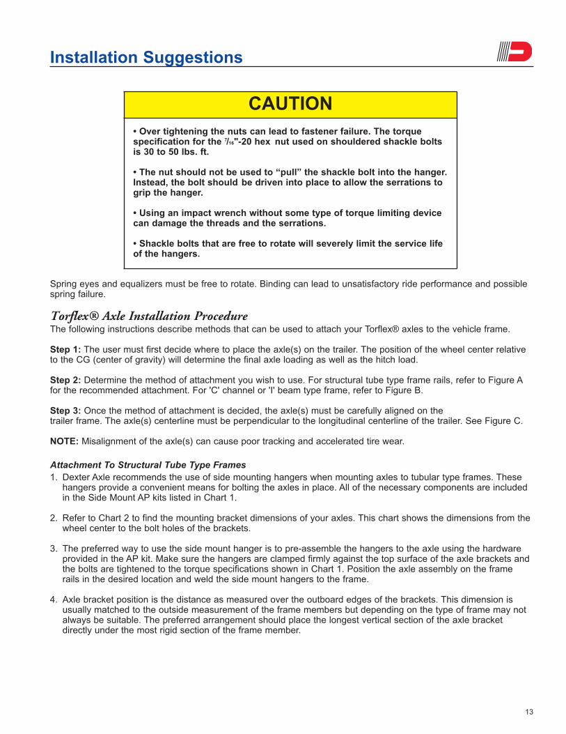
Installation procedures for leaf spring axlesMost trailer manufacturers have developed their own techniques for the installation of running gear. The sequencethat the components are installed is not so important as long as it suits your particular production flow. However, it isessential that these components be attached to the vehicle frame in the proper manner to ensure trouble freeperformance. Spring eyes and equalizers must be free to rotate. Binding can lead to unsatisfactory ride performanceand possible spring failure.
Installation Suggestions
CAUTION!Undercutting can result in weakenedcomponents and lead to premature failure.
(REAR HANGER FOR SINGLE AXLE APPLICATION)
13
Spring eyes and equalizers must be free to rotate. Binding can lead to unsatisfactory ride performance and possiblespring failure.
Torflex® Axle Installation ProcedureThe following instructions describe methods that can be used to attach your Torflex® axles to the vehicle frame.
Step 1: The user must first decide where to place the axle(s) on the trailer. The position of the wheel center relativeto the CG (center of gravity) will determine the final axle loading as well as the hitch load.
Step 2: Determine the method of attachment you wish to use. For structural tube type frame rails, refer to Figure Afor the recommended attachment. For 'C' channel or 'I' beam type frame, refer to Figure B.
Step 3: Once the method of attachment is decided, the axle(s) must be carefully aligned on thetrailer frame. The axle(s) centerline must be perpendicular to the longitudinal centerline of the trailer. See Figure C.
NOTE: Misalignment of the axle(s) can cause poor tracking and accelerated tire wear.
Attachment To Structural Tube Type Frames1. Dexter Axle recommends the use of side mounting hangers when mounting axles to tubular type frames. These
hangers provide a convenient means for bolting the axles in place. All of the necessary components are includedin the Side Mount AP kits listed in Chart 1.
2. Refer to Chart 2 to find the mounting bracket dimensions of your axles. This chart shows the dimensions from thewheel center to the bolt holes of the brackets.
3. The preferred way to use the side mount hanger is to pre-assemble the hangers to the axle using the hardwareprovided in the AP kit. Make sure the hangers are clamped firmly against the top surface of the axle brackets andthe bolts are tightened to the torque specifications shown in Chart 1. Position the axle assembly on the framerails in the desired location and weld the side mount hangers to the frame.
4. Axle bracket position is the distance as measured over the outboard edges of the brackets. This dimension isusually matched to the outside measurement of the frame members but depending on the type of frame may notalways be suitable. The preferred arrangement should place the longest vertical section of the axle bracketdirectly under the most rigid section of the frame member.
Installation Suggestions
CAUTION• Over tightening the nuts can lead to fastener failure. The torquespecification for the 7/16"-20 hex nut used on shouldered shackle boltsis 30 to 50 lbs. ft.
• The nut should not be used to “pull” the shackle bolt into the hanger.Instead, the bolt should be driven into place to allow the serrations togrip the hanger.
• Using an impact wrench without some type of torque limiting devicecan damage the threads and the serrations.
• Shackle bolts that are free to rotate will severely limit the service lifeof the hangers.

14
Side mount hangers should be welded to frame with three (3) 1/4" fillet welds, 21/2" long on each side of the hangerand a fillet weld on each end. Welds should meet the quality standards of the American Welding Society, D1.1,Structural Welding Code.
Attaching Parts Kits - Torque Specifications (Chart 1)
Side mount hangers and fasteners for mounting axle are provided in AP (attaching parts) kit shown in Chart 1.Torque fasteners to levels specified in Chart 1.
Attachment to 'C' Channel or 'I' Beam Type Frames1. Refer to Chart 2 to find the mounting bracket dimensions of your axles. This chart shows the dimensions from the
wheel center to the bolt holes of the brackets.
2. Lay out the bolt hole locations on the bottom flanges of the frame rails. Make sure the hole pattern matches themounting brackets of your axles and is properly oriented to allow proper alignment of the axle(s).
3. An alternate method for determining hole location is to position the axle assembly on the frame rails, align itperpendicular to the trailer centerline, clamp in place and transfer the holes directly from the brackets.
4. Drill the holes through the frame rails and attach the axle using the hardware provided in the AP kit. Tighten thebolts to the torque specified in Chart 1.
Washer(s) must be placed against the slotted hole in the axle bracket.NOTE: Low profile brackets have plain round holes.
OUTSIDE FRAME
OUTSIDE BRACKET DIMENSION
Figure ASide Mount Installation
Installation Suggestions
Axle AP Kit Bolt Torque
Size Top Mount Side Mount Size Lbs.-FT
#8 A/P-161-00 A/P-165-00 1/2" 70-90
#9 A/P-161-00 A/P-165-00 1/2" 70-90
#10 A/P-148-00 A/P-166-00 5/8" 120-155
#11 A/P-148-00 A/P-167-00 5/8" 120-155
#12 A/P-148-00 A/P-168-00 5/8" 120-155
#13 A/P-148-00 A/P-169-00 5/8" 120-155

15
Bracket Dimensions (Chart 2)
Installation Suggestions
CAUTION• When bolting to structural shapes that have tapered flanges, bevelwashers must be used to prevent uneven clamping and bending of thefasteners.
“C” channel frames should be reinforced in the area over the axle(s).
Use bevel washers when bolting to structural steel.
Figure BTop Mount Installation
CAUTION• 'C' channel and 'I' beam type frame sections should be reinforced inthe area over the axle mounting brackets. It is recommended that thevertical leg of the axle bracket be positioned directly under the verticalsegment or reinforcement of the frame member.
Torflex®AxleSize
Mounting Hole To Wheel Center - Dim. X (Inches) MountingHole
SpacingStart Angle Of Trailing Arm
45° DN 22.5° DN 10° DN 0° 10° UP 22.5° UP (INCHES)
No Full No Full No Full No Full No Full No Full Dim. D Dim. E
Load Load Load Load Load Load Load Load Load Load Load Load (Top) (Side)
#8 5.2 6.1 6.1 6.4 6.3 6.3 6.4 6.1 6.3 5.7 6.1 5.2 7.75 8.00
#9 6.6 7.9 7.9 8.4 8.3 8.2 8.4 7.9 8.3 7.4 7.9 6.6 7.75 8.00
#10 6.7 8.0 8.0 8.5 8.4 8.4 8.5 8.0 8.4 7.6 8.0 6.8 8.00 8.00
#11 7.7 9.0 9.0 9.5 9.4 9.4 9.5 9.0 9.4 8.6 9.0 7.7 9.00 9.50
#12 7.7 9.0 9.0 9.5 9.4 9.4 9.5 9.0 9.4 8.6 9.0 7.7 9.00 9.50
#13 7.9 9.2 9.2 9.6 9.5 9.5 9.6 9.2 9.5 8.7 9.2 7.9 10.56 10.56

16
Fender Clearance: Allow 3" over the tire at full load
Frames TypesThe following illustrations show some of the more common frame types and the preferred method of attachment forTorflex® axles. Figures 1 through 4 deal with side mounted axles while Figures 5 through 7 show the top mountedtype. Although Torflex® axles are normally specified by the dimension at the outside or outboard edges of thebrackets to match the outside dimension of the frame, some situations may dictate aligning the vertical leg of thebracket with the web or side of the frame member.
Designers should consider the attachment of the running gear carefully when making decisions about frame types.The reliability and structural integrity of the running gear as well as the frame members can be degraded if axles aremounted to the frame in ways that result in excessive flexing of the components. Side mount hangers can addsupport to the frame while providing a convenient method for running gear attachment. Re-enforcing plates may alsobe added in the areas where the axles are mounted to provide additional support (see illustrations).
Installation Suggestions

17
Installation Suggestions
SIDE MOUNTEDLOW PROFILE
SIDE MOUNTEDHIGH PROFILE
SIDE MOUNTEDLOW PROFILE
REINFORCEMENTRECOMMENDED
SIDE MOUNTEDHIGH PROFILE
REINFORCEMENTRECOMMENDED
SIDE MOUNTEDLOW PROFILE
REINFORCEMENTRECOMMENDED
SIDE MOUNTEDHIGH PROFILE
REINFORCEMENTRECOMMENDED
Figure 1
Figure 2
Figure 3

18
Installation Suggestions
SIDE MOUNTEDLOW PROFILE
REINFORCEMENTRECOMMENDED
SIDE MOUNTEDHIGH PROFILE
REINFORCEMENTRECOMMENDED
TOP MOUNTEDLOW PROFILE
REINFORCEMENTRECOMMENDED
TOP MOUNTEDHIGH PROFILE
REINFORCEMENTRECOMMENDED
TOP MOUNTEDLOW PROFILE
REINFORCEMENTRECOMMENDED
TOP MOUNTEDHIGH PROFILE
REINFORCEMENTRECOMMENDED
Figure 4
Figure 5
Figure 6

19
Designers should consider the attachment of the running gear carefully when making decisions about frame types.The reliability and structural integrity of the running gear as well as the frame members can be degraded if axles aremounted to the frame in ways that result in excessive flexing of the components. Side mount hangers can addsupport to the frame while providing a convenient method for running gear attachment. Re-enforcing plates may alsobe added in the areas where the axles are mounted to provide additional support (see illustrations).
Axle Alignment
To insure proper tracking, the axle must be placed on the frame perpendicular to the centerline of the vehicle. Theaccuracy must be within plus or minus one half degree. For multiple axle applications, each axle must be parallelwith the others within one sixteenth of an inch when measured at the wheel centers.
NOTE: When laying out the position for the axle(s), measuring from the front cross member should only be done ifthe cross member has been checked for squareness to the frame centerline. Any error in the cross member will betransferred to the axle and can result in poor tracking and excessive tire wear.
Installation Suggestions
TOP MOUNTEDLOW PROFILE
REINFORCEMENTRECOMMENDED
TOP MOUNTEDHIGH PROFILE
REINFORCEMENTRECOMMENDED
Figure 7
Figure C

20
WHAT PRODUCTS ARE COVEREDAll Dexter trailer axles, suspensions, and brake controlsystems excluding Dexter 6000 series Manufactured HousingAxles.
LIMITED 2 YEAR WARRANTYDexter Axle warrants to the original purchaser that its axles,suspension systems, and E/H hydraulic brake actuators shallbe free from defects in material and workmanship for a periodof two (2) years from the date of first sale of the trailerincorporating such components.
LIMITED 5 YEAR WARRANTYDexter Axle warrants to the original purchaser that itsNev-R-Lube™ bearings and the suspension components onlyof its Torflex® Axles shall be free from defects in material andworkmanship for a period of five (5) years from the date of firstsale of the trailer incorporating such components.
LIMITED 7 YEAR WARRANTYDexter Axle warrants to the original purchaser that its PredatorSeries™ electric brake controllers shall be free from defects inmaterial and workmanship for a period of seven (7) years fromthe date of purchase.
EXCLUSIVE REMEDYDexter Axle will, at its option, repair or replace the affectedcomponents of any defective axle, repair or replace the entiredefective axle, or refund the then-current list price of the axle.In all cases, a reasonable time period must be allowed forwarranty repairs to be completed. Allowance will only be madefor installation costs specifically approved by Dexter Axle.
WHAT YOU MUST DOIn order to make a claim under these warranties:1. You must be the original purchaser of the vehicle in which
the Spring Suspension Axles or Torflex® Axles wereoriginally installed.
2. You must promptly notify us within the warranty period ofany defect, and provide us with the axle serial number andany substantiation which may include, but is not limited to,the return of part(s) that we may reasonably request.
3. The axles or suspensions must have been installed andmaintained in accordance with good industry practice andany specific Dexter Axle recommendations, including thosespecified in Dexter Axle’s publication “OperationMaintenance Service Manual.”
EXCLUSIONSThese warranties do not extend to or do not cover defectscaused by:1. The connecting of brake wiring to the trailer wiring or trailer
wiring to the towing vehicle wiring.2. The attachment of the running gear to the frame.3. Hub imbalance, or any damage caused thereby.4. Parts not supplied by Dexter Axle.5. Any damage whatever caused by or related to any
alteration of the axle including welding supplementalbrackets to the axle.
Dexter Axle Limited Warranty
6. Use of an axle on a unit other than the unit to which it wasoriginally mounted.
7. Normal wear and tear.8. Alignment.9. Improper installation.10.Unreasonable use (including failure to provide reasonable
and necessary maintenance as specified in Dexter Axle’spublication “Operation Maintenance Service Manual”including required maintenance after “Prolonged Storage”).
11. Improper wheel nut torque.12.Cosmetic finish or corrosion.
LIMITATIONS1. In all cases, Dexter Axle reserves the right to fullysatisfy its obligations under the Limited Warranties byrefunding the then-current list price of the defectiveaxle (or, if the axle has been discontinued, of the mostnearly comparable current product).
2. Dexter Axle reserves the right to furnish a substitute orreplacement component or product in the event an axle orany component of the axle is discontinued or is otherwiseunavailable.
3. These warranties are nontransferable.
GENERALTHE FOREGOING WARRANTIES ARE EXCLUSIVE AND INLIEU OF ALL OTHER WARRANTIES EXCEPT THAT OFTITLE, WHETHER WRITTEN, ORAL OR IMPLIED, IN FACTOR IN LAW (INCLUDING ANY WARRANTY OFMERCHANTABILITY OR FITNESS FOR A PARTICULARPURPOSE).
These warranties give you specific legal rights, and you mayalso have other rights which vary from state to state.
THE DURATION OF ANY IMPLIED WARRANTIES,INCLUDING THE IMPLIED WARRANTIES OFMERCHANTABILITY AND FITNESS FOR A PARTICULARPURPOSE, ARE LIMITED TO THE DURATION OF THEEXPRESS WARRANTIES HEREIN. DEXTER AXLE HEREBYEXCLUDES INCIDENTAL AND CONSEQUENTIALDAMAGES, INCLUDING LOSS OF TIME, INCONVENIENCE,LOSS OF USE, TOWING FEES, TELEPHONE CALLS ORCOST OF MEALS, FOR ANY BREACH OF ANY EXPRESSOR IMPLIED WARRANTY, INCLUDING THE IMPLIEDWARRANTIES OF MERCHANTABILITY AND FITNESS FORA PARTICULAR PURPOSE.
Some states do not allow limitations on how long an impliedwarranty lasts, or the exclusion or limitation of incidental orconsequential damages, so the above exclusion or limitationmay not apply to you.
Inquiries regarding these warranties should be sent to:
Dexter AxleP.O. Box 250Elkhart, Indiana 46515

Dexter Axle222 Collins Rd.Elkhart, IN 46516Fax (574) 295-8094Ph (574) 295-1900
Dexter AxleWest Pearl St.Fremont, IN 46737Fax (260) 495-1701Ph (260) 495-5100
Dexter AxlePerimeter RdMonticello, GA 31064Fax (706) 468-2966Ph (706) 468-6495
Dexter Axle2700 S. Yates Ave.Los Angeles, CA 90040Fax (323) 724-8193Ph (323) 726-3157
Dexter Axle500 S.E. 27th St.El Reno, OK 73036Fax (405) 262-9089Ph (405) 262-6700
Dexter AxleRoad 75 EastAlbion, IN 46701Fax (260) 636-3030Ph (260) 636-2195
Dexter Axle11870 N. 650 EastN. Manchester, IN 46962Fax (260) 982-7511Ph (260) 982-4047
Company Headquarters2900 Industrial Parkway East
Elkhart, IN 46516Fax (574) 295-8666Ph (574) 295-7888
Dexter Axle1 Municipal Dr.Carrollton, MO 64633Fax (660) 542-1133Ph (660) 542-2232
NO PART OF THIS CATALOG MAY BE REPRODUCED WITHOUT DEXTER AXLE’S PERMISSION.ALL PART NUMBERS, DIMENSIONS AND SPECIFICATIONS IN THIS CATALOG ARE SUBJECT
TO CHANGE WITHOUT NOTICE.
Visit us online at www.dexteraxle.com
Genuine Dexter axles and components are availablenationwide from our plant locations listed below or throughour network of distributors. Check our website for thedistributor nearest you.
www.dexteraxle.com2900 Industrial Parkway East • Elkhart, IN 46516
Fax: 574-295-8666 • Ph. 574-295-7888
www.dexteraxle.com
APPLICATIONS MANUAL
11/06 © Dexter Axle 2006LIT-008-00