Embed Size (px)
Citation preview
METRA. THE WORLD’S BEST KITS.™
© COPYRIGHT 2004-2011 METRA ELECTRONICS CORPORATION
APPLICATIONS
1-800-221-0932 metraonline.com
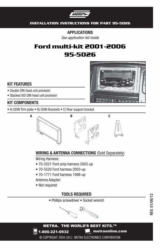
INSTALLATION INSTRUCTIONS FOR PART 95-5026
REV.
01/
06/1
2WIRING & ANTENNA CONNECTIONS (Sold Separately) Wiring Harness: • 70-5521 Ford amp harness 2003-up• 70-5520 Ford harness 2003-up• 70-1771 Ford harness 1998-upAntenna Adapter:• Not required
• Phillips screwdriver • Socket wrench
TOOLS REQUIRED
• A) DDIN Trim plate • B) DDIN Brackets • C) Rear support bracket
KIT FEATURES
KIT COMPONENTS
B CA
• Double DIN head unit provision• Stacked ISO DIN head unit provision
Ford multi-kit 2001-200695-5026
See application list inside
95-5026
Applications
CAUTION: Metra recommends disconnecting the negative battery terminal before beginning any installation. All accessories, switches, and especially air bag indicator lights must be plugged in before reconnecting the battery or cycling the ignition.
Note: Refer to the instructions included with the aftermarket radio.
FordMustang 2001-2004Expedition 2003-2006Explorer 2002-2005
LincolnNavigator 2003-2006Aviator 2003-2005
MercuryMountaineer 2002-2005
KNOWLEDGE IS POWEREnhance your installation and fabrication skills by enrolling in the most recognized and respected mobile electronics school in our industry.Log onto www.installerinstitute.com or call 800-354-6782 for more information and take steps toward a better tomorrow.
Metra recommends MECP certified technicians
Table of Contents
Dash Disassembly
- Ford Mustang 2001-2004 ............................................................................................... 4- Ford Expedition 2003-2006 ............................................................................................. 5- Ford Explorer 2002-2005 ................................................................................................ 6- Lincoln Navigator 2003-2006 .......................................................................................... 7- Lincoln Aviator 2003-2005 .............................................................................................. 8- Mercury Mountaineer 200 ............................................................................................... 6
Kit Assembly
- Double DIN head unit provision ........................................................................................ 9- Stacked ISO DIN head unit provision .............................................................................. 10
95-5026

4
Dash Disassembly 95-5026
Ford Mustang 2001-2004
1. Unclip and remove shift lever trim panel. (Figure A)
2. Unclip and remove the entire panel surrounding the radio and climate controls including the vents.
3. Remove (2) 9/32” screws securing radio. (Figure B)
Continue to kit assembly
(Figure A)
(Figure B)
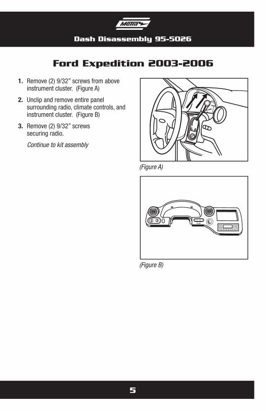
Ford Expedition 2003-2006
1. Remove (2) 9/32” screws from above instrument cluster. (Figure A)
2. Unclip and remove entire panel surrounding radio, climate controls, and instrument cluster. (Figure B)
3. Remove (2) 9/32” screws securing radio.
Continue to kit assembly
(Figure A)
(Figure B)
Dash Disassembly 95-5026
5
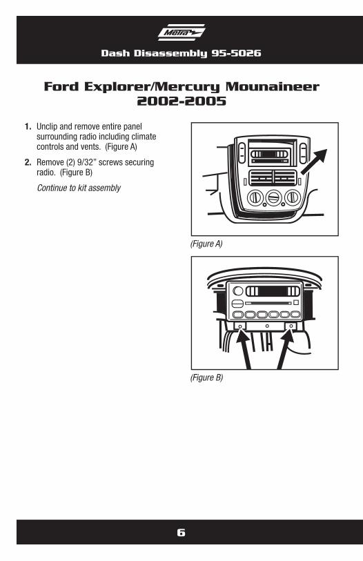
Ford Explorer/Mercury Mounaineer2002-2005
1. Unclip and remove entire panel surrounding radio including climate controls and vents. (Figure A)
2. Remove (2) 9/32” screws securing radio. (Figure B)
Continue to kit assembly
(Figure A)
(Figure B)
Dash Disassembly 95-5026
6
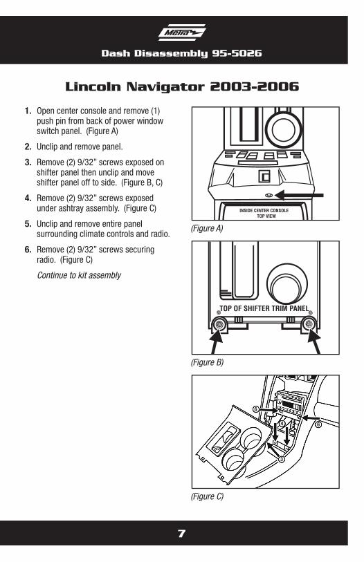
Lincoln Navigator 2003-2006
1. Open center console and remove (1) push pin from back of power window switch panel. (Figure A)
2. Unclip and remove panel.
3. Remove (2) 9/32” screws exposed on shifter panel then unclip and move shifter panel off to side. (Figure B, C)
4. Remove (2) 9/32” screws exposed under ashtray assembly. (Figure C)
5. Unclip and remove entire panel surrounding climate controls and radio.
6. Remove (2) 9/32” screws securing radio. (Figure C)
Continue to kit assembly
INSIDE CENTER CONSOLE TOP VIEW
(Figure A)
(Figure C)
TOP OF SHIFTER TRIM PANEL
(Figure B)
Dash Disassembly 95-5026
7
4 6
6
3
Dash Disassembly 95-5026
8
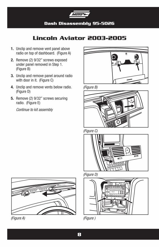
Lincoln Aviator 2003-2005
1. Unclip and remove vent panel above radio on top of dashboard. (Figure A)
2. Remove (2) 9/32” screws exposed under panel removed in Step 1. (Figure B)
3. Unclip and remove panel around radio with door in it. (Figure C)
4. Unclip and remove vents below radio. (Figure D)
5. Remove (2) 9/32” screws securing radio. (Figure E)
Continue to kit assembly
(Figure B)
105.9
(Figure )
(Figure C)
(Figure D)
(Figure A)
Kit Assembly 95-5026
9
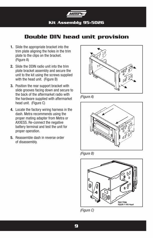
Double DIN head unit provision
1. Slide the appropriate bracket into the trim plate aligning the holes in the trim plate to the clips on the bracket. (Figure A)
2. Slide the DDIN radio unit into the trim plate bracket assembly and secure the unit to the kit using the screws supplied with the head unit. (Figure B)
3. Position the rear support bracket with slide grooves facing down and secure to the back of the aftermarket radio with the hardware supplied with aftermarket head unit. (Figure C)
4. Locate the factory wiring harness in the dash. Metra recommends using the proper mating adapter from Metra or AXXESS. Re-connect the negative battery terminal and test the unit for proper operation.
5. Reassemble dash in reverse order of disassembly.
(Figure A)
(Figure C)
(Figure B)
10
Kit Assembly 95-5026
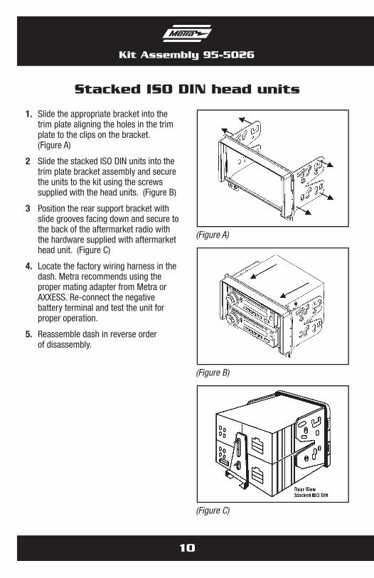
1. Slide the appropriate bracket into the trim plate aligning the holes in the trim plate to the clips on the bracket. (Figure A)
2 Slide the stacked ISO DIN units into the trim plate bracket assembly and secure the units to the kit using the screws supplied with the head units. (Figure B)
3 Position the rear support bracket with slide grooves facing down and secure to the back of the aftermarket radio with the hardware supplied with aftermarket head unit. (Figure C)
4. Locate the factory wiring harness in the dash. Metra recommends using the proper mating adapter from Metra or AXXESS. Re-connect the negative battery terminal and test the unit for proper operation.
5. Reassemble dash in reverse order of disassembly.
Stacked ISO DIN head units
(Figure A)
(Figure C)
(Figure B)

Notes

METRA. THE WORLD’S BEST KITS.™
© COPYRIGHT 2004-2011 METRA ELECTRONICS CORPORATION 1-800-221-0932 metraonline.com
INSTALLATION INSTRUCTIONS FOR PART 95-5026
REV.
01/
06/1
2
METRA. THE WORLD’S BEST KITS.™
© COPYRIGHT 2004-2011 METRA ELECTRONICS CORPORATION
APLICACIONES
1-800-221-0932 metraonline.com
INSTRUCCIONES DE INSTALACIÓN PARA LA PIEZA 95-5026
REV.
01/
06/1
2
• Phillips screwdriver • Socket wrench
HERRAMIENTAS REQUERIDAS
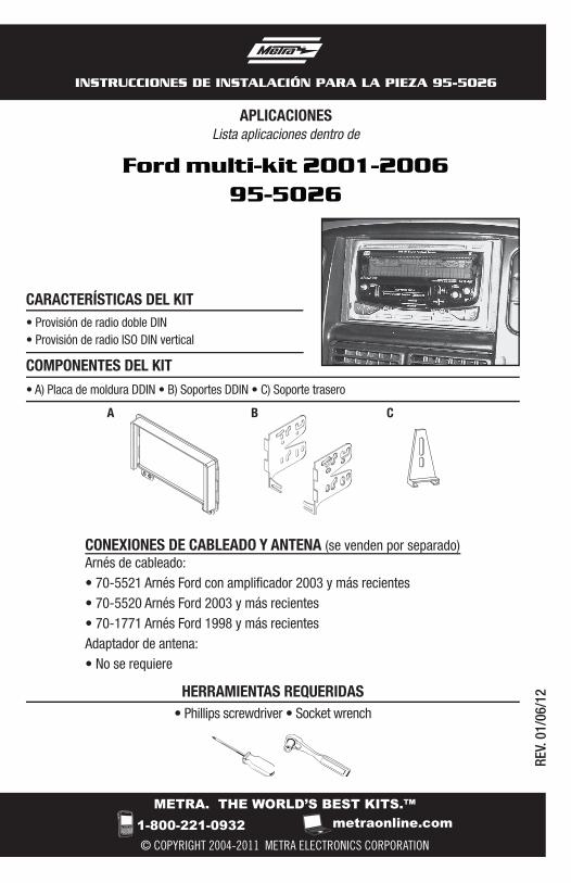
• A) Placa de moldura DDIN • B) Soportes DDIN • C) Soporte trasero
CARACTERÍSTICAS DEL KIT
COMPONENTES DEL KIT
B CA
• Provisión de radio doble DIN• Provisión de radio ISO DIN vertical
Ford multi-kit 2001-200695-5026
Lista aplicaciones dentro de
CONEXIONES DE CABLEADO Y ANTENA (se venden por separado)Arnés de cableado:• 70-5521 Arnés Ford con amplificador 2003 y más recientes• 70-5520 Arnés Ford 2003 y más recientes• 70-1771 Arnés Ford 1998 y más recientesAdaptador de antena: • No se requiere
95-5026
Aplicaciones
PRECAUCIÓN: Metra recomienda desconectar el terminal negativo de la batería antes de comenzar cualquier instalación. Todos los accesorios, interruptores y, especialmente, las luces indicadoras de airbag deben estar enchufados antes de volver a conectar la batería o comenzar el ciclo de ignición.
Nota: Asimismo, remítase a las instrucciones incluidas con el radio de posventa.
FordMustang 2001-2004Expedition 2003-2006Explorer 2002-2005
LincolnNavigator 2003-2006Aviator 2003-2005
MercuryMountaineer 2002-2005
Metra recomienda técnicos con certificación del Programa de Certificación en Electrónica Móvil (Mobile Electronics Certification Program, MECP).
KNOWLEDGE IS POWEREnhance your installation and fabrication skills by enrolling in the most recognized and respected mobile electronics school in our industry.Log onto www.installerinstitute.com or call 800-354-6782 for more information and take steps toward a better tomorrow.
EL CONOCIMIENTO ES PODERMejore sus habilidades de instalación y fabricación inscribiéndose en la escuela de dispositivos electrónicos móviles más reconocida y respetada de nuestra industria. Regístrese en www.installerinstitute.com o llame al 800-354-6782 para obtener más información y avance hacia un futuro mejor.
Indice
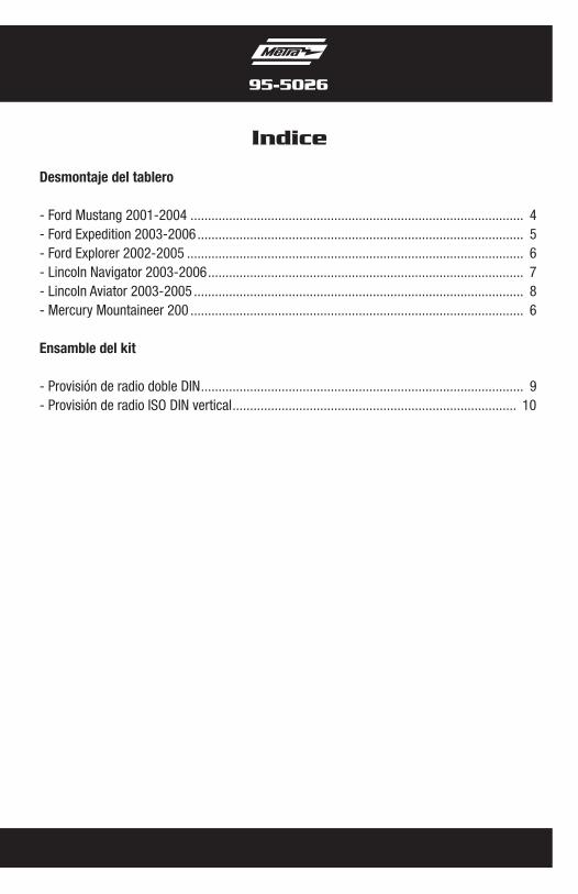
Desmontaje del tablero
- Ford Mustang 2001-2004 ............................................................................................... 4- Ford Expedition 2003-2006 ............................................................................................. 5- Ford Explorer 2002-2005 ................................................................................................ 6- Lincoln Navigator 2003-2006 .......................................................................................... 7- Lincoln Aviator 2003-2005 .............................................................................................. 8- Mercury Mountaineer 200 ............................................................................................... 6
Ensamble del kit
- Provisión de radio doble DIN ............................................................................................ 9- Provisión de radio ISO DIN vertical ................................................................................. 10
95-5026
4
Desmontaje del tablero 95-5026
Ford Mustang 2001-2004
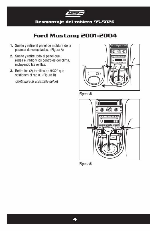
1. Suelte y retire el panel de moldura de la palanca de velocidades. (Figura A)
2. Suelte y retire todo el panel que rodea el radio y los controles del clima, incluyendo las rejillas.
3. Retire los (2) tornillos de 9/32” que sostienen el radio. (Figura B)
Continuará al ensamble del kit
(Figura A)
(Figura B)
Ford Expedition 2003-2006
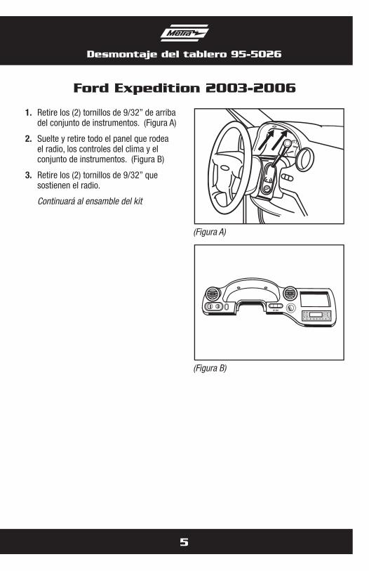
1. Retire los (2) tornillos de 9/32” de arriba del conjunto de instrumentos. (Figura A)
2. Suelte y retire todo el panel que rodea el radio, los controles del clima y el conjunto de instrumentos. (Figura B)
3. Retire los (2) tornillos de 9/32” que sostienen el radio.
Continuará al ensamble del kit
(Figura A)
(Figura B)
Desmontaje del tablero 95-5026
5
Ford Explorer/Mercury Mounaineer2002-2005
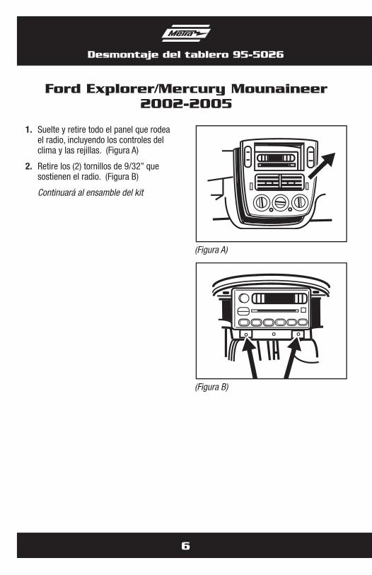
1. Suelte y retire todo el panel que rodea el radio, incluyendo los controles del clima y las rejillas. (Figura A)
2. Retire los (2) tornillos de 9/32” que sostienen el radio. (Figura B)
Continuará al ensamble del kit
(Figura A)
(Figura B)
Desmontaje del tablero 95-5026
6
Lincoln Navigator 2003-2006
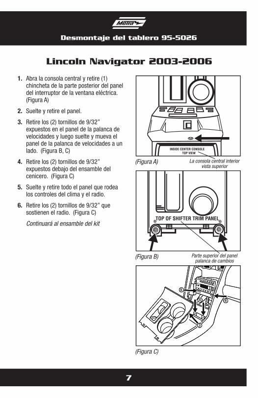
1. Abra la consola central y retire (1) chincheta de la parte posterior del panel del interruptor de la ventana eléctrica. (Figura A)
2. Suelte y retire el panel.
3. Retire los (2) tornillos de 9/32” expuestos en el panel de la palanca de velocidades y luego suelte y mueva el panel de la palanca de velocidades a un lado. (Figura B, C)
4. Retire los (2) tornillos de 9/32” expuestos debajo del ensamble del cenicero. (Figura C)
5. Suelte y retire todo el panel que rodea los controles del clima y el radio.
6. Retire los (2) tornillos de 9/32” que sostienen el radio. (Figura C)
Continuará al ensamble del kit
INSIDE CENTER CONSOLE TOP VIEW
(Figura A)
(Figura C)
TOP OF SHIFTER TRIM PANEL
(Figura B)
Desmontaje del tablero 95-5026
7
4 6
6
3
La consola central interiorvista superior
Parte superior del panel palanca de cambios
Desmontaje del tablero 95-5026
8
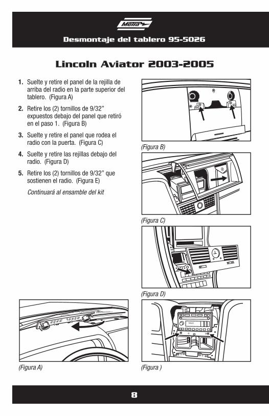
Lincoln Aviator 2003-2005
1. Suelte y retire el panel de la rejilla de arriba del radio en la parte superior del tablero. (Figura A)
2. Retire los (2) tornillos de 9/32” expuestos debajo del panel que retiró en el paso 1. (Figura B)
3. Suelte y retire el panel que rodea el radio con la puerta. (Figura C)
4. Suelte y retire las rejillas debajo del radio. (Figura D)
5. Retire los (2) tornillos de 9/32” que sostienen el radio. (Figura E)
Continuará al ensamble del kit
(Figura B)
105.9
(Figura )
(Figura C)
(Figura D)
(Figura A)
Ensamble del kit 95-5026
9
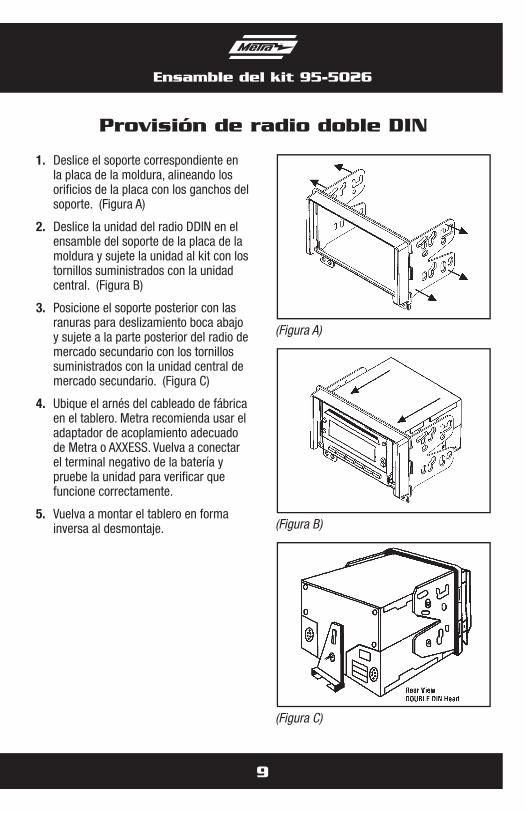
Provisión de radio doble DIN
1. Deslice el soporte correspondiente en la placa de la moldura, alineando los orificios de la placa con los ganchos del soporte. (Figura A)
2. Deslice la unidad del radio DDIN en el ensamble del soporte de la placa de la moldura y sujete la unidad al kit con los tornillos suministrados con la unidad central. (Figura B)
3. Posicione el soporte posterior con las ranuras para deslizamiento boca abajo y sujete a la parte posterior del radio de mercado secundario con los tornillos suministrados con la unidad central de mercado secundario. (Figura C)
4. Ubique el arnés del cableado de fábrica en el tablero. Metra recomienda usar el adaptador de acoplamiento adecuado de Metra o AXXESS. Vuelva a conectar el terminal negativo de la batería y pruebe la unidad para verificar que funcione correctamente.
5. Vuelva a montar el tablero en forma inversa al desmontaje.
(Figura A)
(Figura C)
(Figura B)
10
Ensamble del kit 95-5026
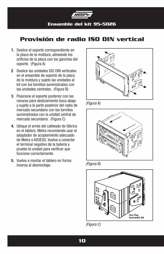
1. Deslice el soporte correspondiente en la placa de la moldura, alineando los orificios de la placa con los ganchos del soporte. (Figura A)
2 Deslice las unidades ISO DIN verticales en el ensamble de soporte de la placa de la moldura y sujete las unidades al kit con los tornillos suministrados con las unidades centrales. (Figura B)
3 Posicione el soporte posterior con las ranuras para deslizamiento boca abajo y sujete a la parte posterior del radio de mercado secundario con los tornillos suministrados con la unidad central de mercado secundario. (Figura C)
4. Ubique el arnés del cableado de fábrica en el tablero. Metra recomienda usar el adaptador de acoplamiento adecuado de Metra o AXXESS. Vuelva a conectar el terminal negativo de la batería y pruebe la unidad para verificar que funcione correctamente.
5. Vuelva a montar el tablero en forma inversa al desmontaje.
Provisión de radio ISO DIN vertical
(Figura A)
(Figura C)
(Figura B)

Notas

METRA. THE WORLD’S BEST KITS.™
© COPYRIGHT 2004-2011 METRA ELECTRONICS CORPORATION 1-800-221-0932 metraonline.com
INSTRUCCIONES DE INSTALACIÓN PARA LA PIEZA 95-5026
REV.
01/
06/1
2