Embed Size (px)
Citation preview
APPLICATIONS OF THEORY OF ELASTICITY IN ROCK MECHANICS
1. INTRODUCTION
2. CLOSED-FORM SOLUTIONS VS. NUMERICAL METHODS
3. TWO-DIMENSIONAL FORMULATION
3.1 Plane Strain Analysis3.2 Plane Stress Analysis3.3 Generalized Plane Strain Analysis3.4 Analysis in Polar or Cylindrical Coordinates
4. EXAMPLES
4.1 Hollow Cylinder under Pressure4.2 Circular Hole Drilled Under a Triaxial Principal Stress Field at Infinity4.3 Circular Hole Drilled Under a Triaxial Stress Field-General Solution
5. USING STRESSES IN ROCK ENGINEERING
6. REFERENCES
CVEN 5768 - Lecture Notes 6 Page 1© B. Amadei
1. INTRODUCTION
The theory of elasticity is used widely in rock mechanics to predict how rock masses respond toloads and excavation (surface and underground). The assumptions inherent to the theory ofelasticity are:
C the material is elastic (linear or non-linear) which implies an immediate response during loading and a fully reversible response upon unloading,
C the material behaves as a continuum.
If time is involved (time-deferred response), the theory of viscoelasticity should be used instead.
In classical linear elastic theory, it is assumed that no distinction needs to be made between theLagrangian and Eulerian descriptions of strain. The six components of stress, the six componentsof strain and the three components of displacement must satisfy some basic equations calledfield equations, e.g. 3 equations of equilibrium, 6 equations relating strains to displacement and6 equations relating stresses to strains. Thus, a total of 15 equations are available to solve for 15unknowns, i.e. 6 stresses, 6 strains, and 3 displacements.
In solving for the 15 unknowns, stresses and displacements must satisfy the boundary conditionswhich can take different forms: prescribed displacements only, prescribed stresses (surfacetractions) only, or mixed stress and displacement boundary conditions. In all cases, the bodyforces are assumed to be given throughout the continuum.
Most problems in rock mechanics are three-dimensional. Under certain assumptions of planestrain or plane stress, a two-dimensional approximation can be made. In plane stress problems,the geometry of the rock mass is essentially that of a plate with one dimension much smallerthan the others. Plane stress is used for instance to model surface problems. In plane strainproblems, the geometry of the body is essentially that of a prismatic cylinder with one dimensionmuch larger than the others. These notes are limited to two-dimensional elastostatic problems.
Rocks and rocks masses do not always behave elastically or as continua. Nevertheless, for awide range of engineering problems, useful solutions may be obtained by treating the rock as ahomogeneous, linearly elastic continuum. If necessary, anisotropy and nonlinearity may be takeninto account. Despite its limitation, the elastic analysis can be used to evaluate a number offactors of importance in rock engineering. Examination of solutions to elastic stress distributionproblems can provide useful qualitative guidelines for the design of engineering structures builtin or on rock. For instance, elastic stress analysis provides an assessment of the extent ofcompression and tension zones, the zones of influence of excavations, the stress intensity and theextent of highly stressed zones. A failure criterion can be superposed on the elastic solution toassess the extent of overstressed rock around the excavations of interest. The basic assumptionbehind this approach is that the existence of the plastic zone does not disturb the stress
CVEN 5768 - Lecture Notes 6 Page 2© B. Amadei
distribution. A failure criterion can also be included in the solution (elasto-plastic analysis).Elastic analysis can also help in determining the rock deformation associated with the stresses.Deformation, and not stress, may sometimes become the critical factor in rock engineeringdesign.
2. CLOSED-FORM SOLUTIONS VS. NUMERICAL METHODS
Elasticity problems can be solved using closed-form solutions or numerical methods dependingon the complexity of the material of interest and the geometry of the problem being addressed.
Closed-form solutions are usually used when the material is homogeneous, isotropic (oranisotropic), and the boundary of the problem is of simple shape. Closed-form solutions areavailable in various texts such as Obert and Duvall (1967), Timoshenko and Goodier (1970),Lekhnitskii (1977), Jaeger and Cook (1979), Poulos and Davis (1974), etc... Closed-formsolutions can be derived, for instance, to study the response of a rock mass to surface loads, andsurface or underground excavation. Various closed-form solutions are also available for theanalysis of field and laboratory rock mechanics tests.
Numerical methods are used instead when the material has a complex constitutive behavior(non-linear behavior, elasto-plastic, etc..) and/or the problem geometry is complicated. The mostfrequently applied numerical procedures in rock engineering and rock mechanics are the finiteelement method (FEM), boundary element methods (BEM), and the discrete element methods(DEM). Both FEM and BEM are used when the rock mass is modelled as a continuum withseveral discrete planes of weakness. DEM is used when the rock mass contains a large numberof blocks, and its deformation is controlled mostly by the opening of, closing of, and slidingalong the discontinuities and to a lesser extent by the block deformation. Hybrid methods arealso used in order to preserve the advantages of each method and eliminate their disadvantages.A review of the numerical methods in rock mechanics can be found in Pande et al. (1990).
Finite Element Method
C efficient numerical solution procedure,C complex constitutive behavior can be modelled,C requires discretization of the complete problem domain,C arbitrary external boundaries are needed,C the size of the numerical problem to be solved is related to the volume of the problem
domain.
Boundary Element Methods
C no requirement to define arbitrary external boundaries from the problem area,C size of the numerical problem increases with the size of surface area of excavation,C volume of the problem is considered explicitly in the analysis,
CVEN 5768 - Lecture Notes 6 Page 3© B. Amadei
(1)
C discretization of problem boundaries only,C low demand on computer storage,C simplicity of data input,C calculate stresses, strains and displacements at points of interest,C limited to rock masses with linear constitutive behavior.
Discrete Element Methods
C analysis of large block movement in geologically complex regions having many joint blocks,
C can be performed by a microcomputer and displayed interactively,C mostly two-dimensional,C precise location of joints needs to be input.
BEM, FEM, DEM Coupling
C BEM for far-field rock mass (continuum) and DEM near-field rock mass (discontinuum),C coupling BEM and FEM eliminates boundaries and uncertainties associated with outer
boundary conditions,C far-field rock mass is a homogeneous continuum modeled with BEM and near-field rock
mass is modeled as a continuum with zones (usually small and localized) of complex constitutive behavior.
3. TWO-DIMENSIONAL FORMULATION
The material is assumed to be isotropic an linearly elastic and under plane strain or plane stress.Body forces are assumed to be absent or constant. Stresses and strains are defined in the x,yplane of an x,y,z coordinate system.
3.1 Plane Strain Analysis
As discussed in Section 4.0 in Lecture Notes 3, plane strain in the x,y plane implies that thedisplacement components u, v and w in the x, y and z directions are such that
The geometry of the body is essentially that of a prismatic cylinder with one dimension (zdirection) much larger than the others. Loading of the body (body and surface forces) is directednormal to the z-axis, and all cross-sections of the body are identically loaded.
In view of equation (1), the strains åxx, åyy and åxy are the only non-vanishing strain components.They satisfy the following compatibility equation
CVEN 5768 - Lecture Notes 6 Page 4© B. Amadei
(2)
(3)
(4)
(5)
(6)
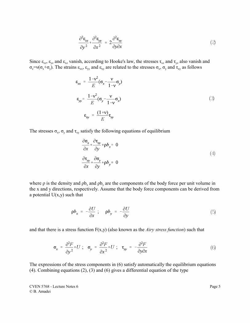
Since åzz, åyz and åxz vanish, according to Hooke's law, the stresses ôxz and ôyz also vanish andóz=í(óx+óy). The strains åxx, åyy and åxy are related to the stresses óx, óy and ôxy as follows
The stresses óx, óy and ôxy satisfy the following equations of equilibrium
where ñ is the density and ñbx and ñby are the components of the body force per unit volume inthe x and y directions, respectively. Assume that the body force components can be derived froma potential U(x,y) such that
and that there is a stress function F(x,y) (also known as the Airy stress function) such that
The expressions of the stress components in (6) satisfy automatically the equilibrium equations(4). Combining equations (2), (3) and (6) gives a differential equation of the type
CVEN 5768 - Lecture Notes 6 Page 5© B. Amadei
(7)
(8)
(9)
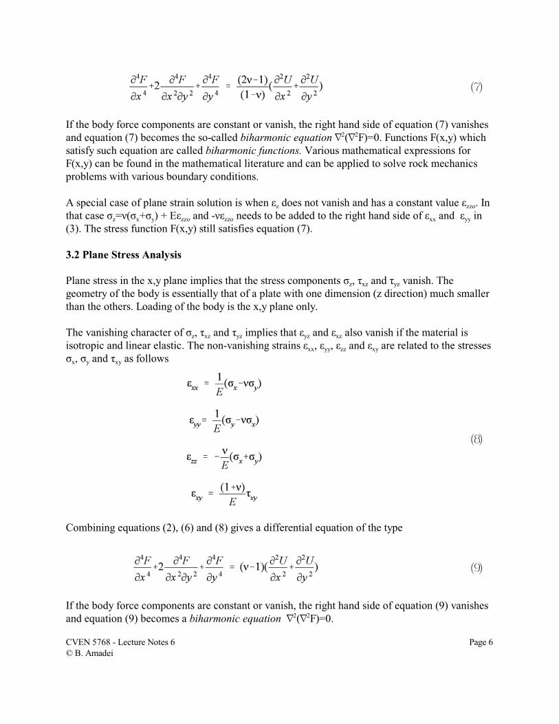
If the body force components are constant or vanish, the right hand side of equation (7) vanishesand equation (7) becomes the so-called biharmonic equation L2(L2F)=0. Functions F(x,y) whichsatisfy such equation are called biharmonic functions. Various mathematical expressions forF(x,y) can be found in the mathematical literature and can be applied to solve rock mechanicsproblems with various boundary conditions.
A special case of plane strain solution is when åz does not vanish and has a constant value åzzo. Inthat case óz=í(óx+óy) + Eåzzo and -íåzzo needs to be added to the right hand side of åxx and åyy in(3). The stress function F(x,y) still satisfies equation (7).
3.2 Plane Stress Analysis
Plane stress in the x,y plane implies that the stress components óz, ôxz and ôyz vanish. Thegeometry of the body is essentially that of a plate with one dimension (z direction) much smallerthan the others. Loading of the body is the x,y plane only.
The vanishing character of óz, ôxz and ôyz implies that åyz and åxz also vanish if the material isisotropic and linear elastic. The non-vanishing strains åxx, åyy, åzz and åxy are related to the stressesóx, óy and ôxy as follows
Combining equations (2), (6) and (8) gives a differential equation of the type
If the body force components are constant or vanish, the right hand side of equation (9) vanishesand equation (9) becomes a biharmonic equation L2(L2F)=0.
CVEN 5768 - Lecture Notes 6 Page 6© B. Amadei
(10)
(11)
(12)
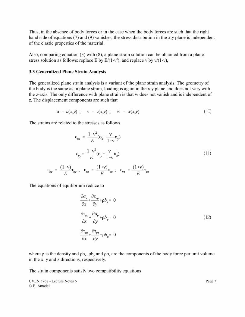
Thus, in the absence of body forces or in the case when the body forces are such that the righthand side of equations (7) and (9) vanishes, the stress distribution in the x,y plane is independentof the elastic properties of the material.
Also, comparing equation (3) with (8), a plane strain solution can be obtained from a planestress solution as follows: replace E by E/(1-í2), and replace í by í/(1-í),
3.3 Generalized Plane Strain Analysis
The generalized plane strain analysis is a variant of the plane strain analysis. The geometry ofthe body is the same as in plane strain, loading is again in the x,y plane and does not vary withthe z-axis. The only difference with plane strain is that w does not vanish and is independent ofz. The displacement components are such that
The strains are related to the stresses as follows
The equations of equilibrium reduce to
where ñ is the density and ñbx, ñby and ñbz are the components of the body force per unit volumein the x, y and z directions, respectively.
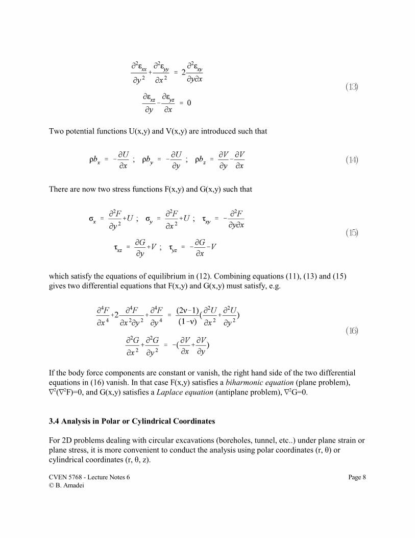
The strain components satisfy two compatibility equations
CVEN 5768 - Lecture Notes 6 Page 7© B. Amadei
(13)
(14)
(15)
(16)
Two potential functions U(x,y) and V(x,y) are introduced such that
There are now two stress functions F(x,y) and G(x,y) such that
which satisfy the equations of equilibrium in (12). Combining equations (11), (13) and (15)gives two differential equations that F(x,y) and G(x,y) must satisfy, e.g.
If the body force components are constant or vanish, the right hand side of the two differentialequations in (16) vanish. In that case F(x,y) satisfies a biharmonic equation (plane problem), L2(L2F)=0, and G(x,y) satisfies a Laplace equation (antiplane problem), L2G=0.
3.4 Analysis in Polar or Cylindrical Coordinates
For 2D problems dealing with circular excavations (boreholes, tunnel, etc..) under plane strain orplane stress, it is more convenient to conduct the analysis using polar coordinates (r, è) orcylindrical coordinates (r, è, z).
CVEN 5768 - Lecture Notes 6 Page 8© B. Amadei
(17)
(18)
(19)
(20)
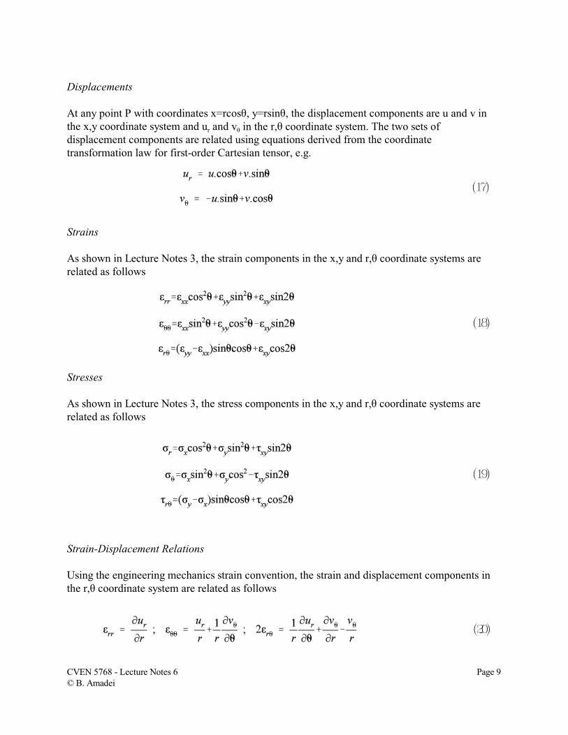
Displacements
At any point P with coordinates x=rcosè, y=rsinè, the displacement components are u and v inthe x,y coordinate system and ur and vè in the r,è coordinate system. The two sets ofdisplacement components are related using equations derived from the coordinatetransformation law for first-order Cartesian tensor, e.g.
Strains
As shown in Lecture Notes 3, the strain components in the x,y and r,è coordinate systems arerelated as follows
Stresses
As shown in Lecture Notes 3, the stress components in the x,y and r,è coordinate systems arerelated as follows
Strain-Displacement Relations
Using the engineering mechanics strain convention, the strain and displacement components inthe r,è coordinate system are related as follows
CVEN 5768 - Lecture Notes 6 Page 9© B. Amadei
(21)
(22)
(23)
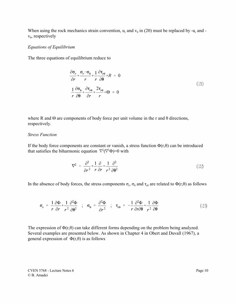
When using the rock mechanics strain convention, ur and vè in (20) must be replaced by -ur and -vè, respectively
Equations of Equilibrium
The three equations of equilibrium reduce to
where R and È are components of body force per unit volume in the r and è directions,respectively.
Stress Function
If the body force components are constant or vanish, a stress function Ö(r,è) can be introducedthat satisfies the biharmonic equation L2(L2Ö)=0 with
In the absence of body forces, the stress components ór, óè and ôrè are related to Ö(r,è) as follows
The expression of Ö(r,è) can take different forms depending on the problem being analyzed.Several examples are presented below. As shown in Chapter 4 in Obert and Duvall (1967), ageneral expression of Ö(r,è) is as follows
CVEN 5768 - Lecture Notes 6 Page 10© B. Amadei
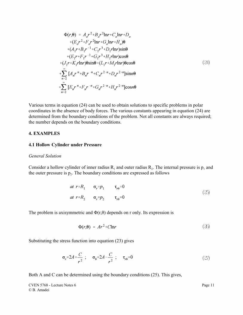
(24)
(25)
(26)
(27)
Various terms in equation (24) can be used to obtain solutions to specific problems in polarcoordinates in the absence of body forces. The various constants appearing in equation (24) aredetermined from the boundary conditions of the problem. Not all constants are always required;the number depends on the boundary conditions.
4. EXAMPLES
4.1 Hollow Cylinder under Pressure
General Solution
Consider a hollow cylinder of inner radius R1 and outer radius R2. The internal pressure is p1 andthe outer pressure is p2. The boundary conditions are expressed as follows
The problem is axisymmetric and Ö(r,è) depends on r only. Its expression is
Substituting the stress function into equation (23) gives
Both A and C can be determined using the boundary conditions (25). This gives,
CVEN 5768 - Lecture Notes 6 Page 11© B. Amadei
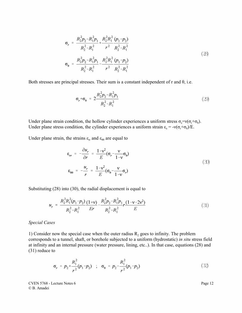
(28)
(29)
(30)
(31)
(32)
Both stresses are principal stresses. Their sum is a constant independent of r and è, i.e.
Under plane strain condition, the hollow cylinder experiences a uniform stress óz=í(ór+óè).Under plane stress condition, the cylinder experiences a uniform strain åz = -í(ór+óè)/E.
Under plane strain, the strains årr and åèè are equal to
Substituting (28) into (30), the radial displacement is equal to
Special Cases
1) Consider now the special case when the outer radius R2 goes to infinity. The problemcorresponds to a tunnel, shaft, or borehole subjected to a uniform (hydrostatic) in situ stress fieldat infinity and an internal pressure (water pressure, lining, etc..). In that case, equations (28) and(31) reduce to
CVEN 5768 - Lecture Notes 6 Page 12© B. Amadei
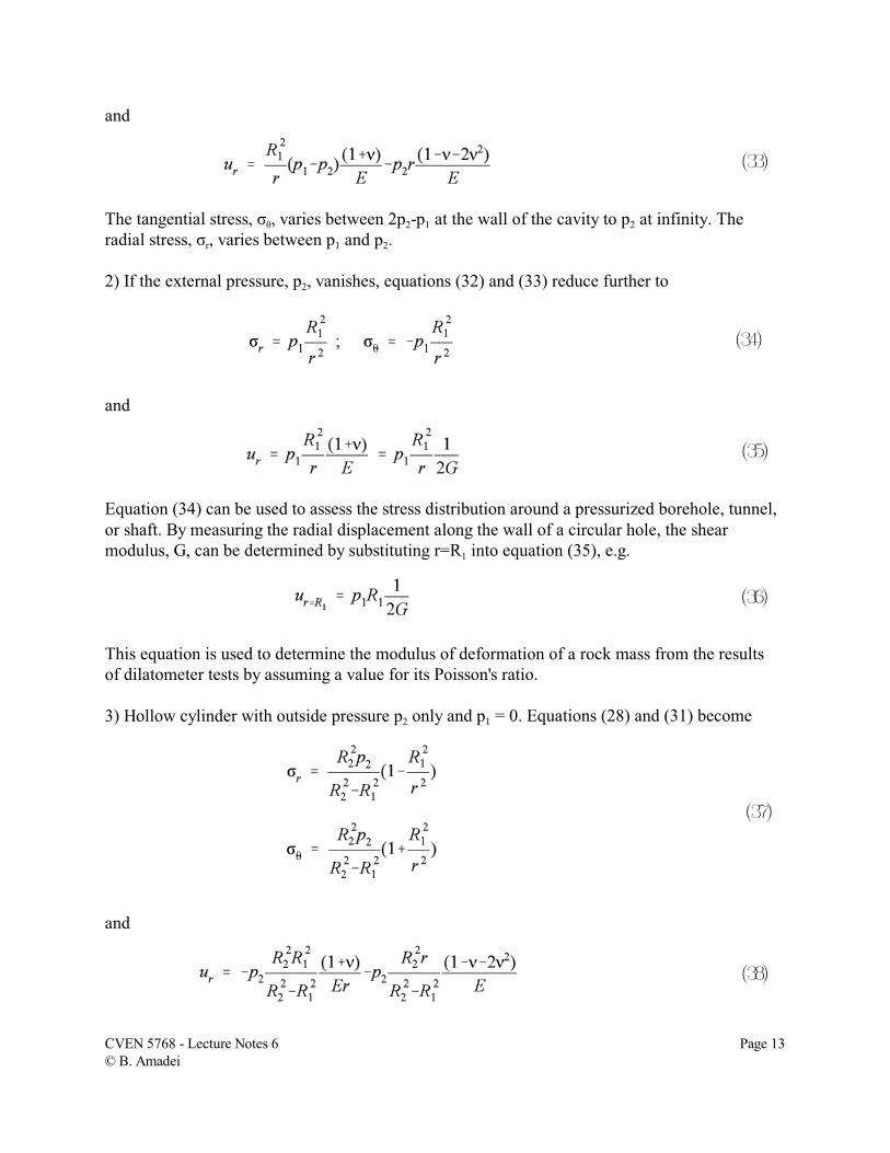
(33)
(34)
(35)
(36)
(37)
(38)
and
The tangential stress, óè, varies between 2p2-p1 at the wall of the cavity to p2 at infinity. Theradial stress, ór, varies between p1 and p2.
2) If the external pressure, p2, vanishes, equations (32) and (33) reduce further to
and
Equation (34) can be used to assess the stress distribution around a pressurized borehole, tunnel,or shaft. By measuring the radial displacement along the wall of a circular hole, the shearmodulus, G, can be determined by substituting r=R1 into equation (35), e.g.
This equation is used to determine the modulus of deformation of a rock mass from the resultsof dilatometer tests by assuming a value for its Poisson's ratio.
3) Hollow cylinder with outside pressure p2 only and p1 = 0. Equations (28) and (31) become
and
CVEN 5768 - Lecture Notes 6 Page 13© B. Amadei
(39)
(40)
(41)
(42)
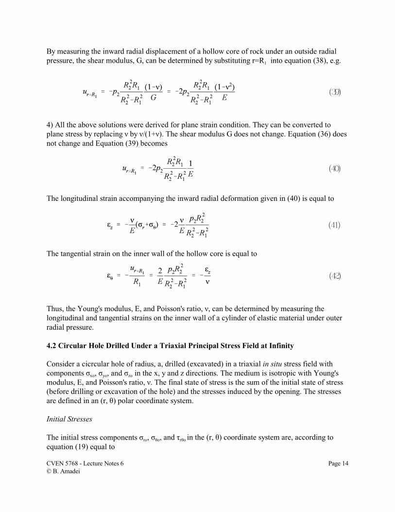
By measuring the inward radial displacement of a hollow core of rock under an outside radialpressure, the shear modulus, G, can be determined by substituting r=R1 into equation (38), e.g.
4) All the above solutions were derived for plane strain condition. They can be converted toplane stress by replacing í by í/(1+í). The shear modulus G does not change. Equation (36) doesnot change and Equation (39) becomes
The longitudinal strain accompanying the inward radial deformation given in (40) is equal to
The tangential strain on the inner wall of the hollow core is equal to
Thus, the Young's modulus, E, and Poisson's ratio, í, can be determined by measuring thelongitudinal and tangential strains on the inner wall of a cylinder of elastic material under outerradial pressure.
4.2 Circular Hole Drilled Under a Triaxial Principal Stress Field at Infinity
Consider a cicrcular hole of radius, a, drilled (excavated) in a triaxial in situ stress field withcomponents óxo, óyo, and ózo in the x, y and z directions. The medium is isotropic with Young'smodulus, E, and Poisson's ratio, í. The final state of stress is the sum of the initial state of stress(before drilling or excavation of the hole) and the stresses induced by the opening. The stressesare defined in an (r, è) polar coordinate system.
Initial Stresses
The initial stress components óro, óèo, and ôrèo in the (r, è) coordinate system are, according toequation (19) equal to
CVEN 5768 - Lecture Notes 6 Page 14© B. Amadei
(43)
(44)
(45)
(46)
(47)
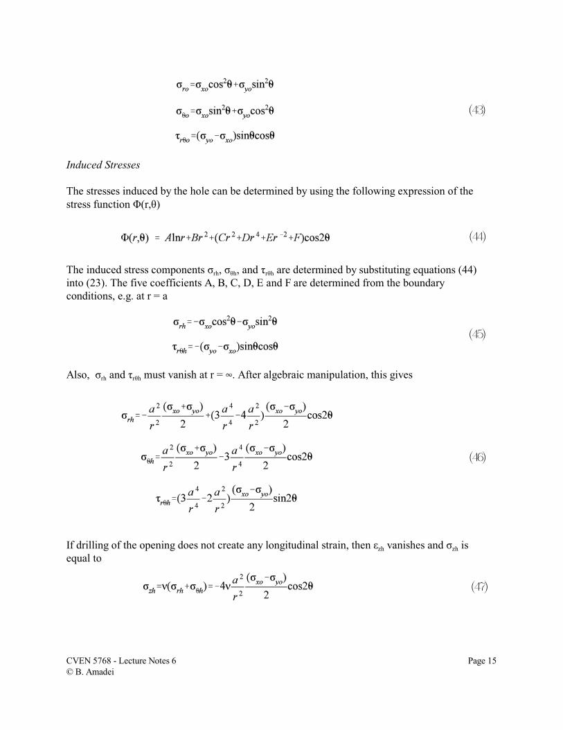
Induced Stresses
The stresses induced by the hole can be determined by using the following expression of thestress function Ö(r,è)
The induced stress components órh, óèh, and ôrèh are determined by substituting equations (44)into (23). The five coefficients A, B, C, D, E and F are determined from the boundaryconditions, e.g. at r = a
Also, órh and ôrèh must vanish at r = 4. After algebraic manipulation, this gives
If drilling of the opening does not create any longitudinal strain, then åzh vanishes and ózh isequal to
CVEN 5768 - Lecture Notes 6 Page 15© B. Amadei
(48)
(49)
(50)
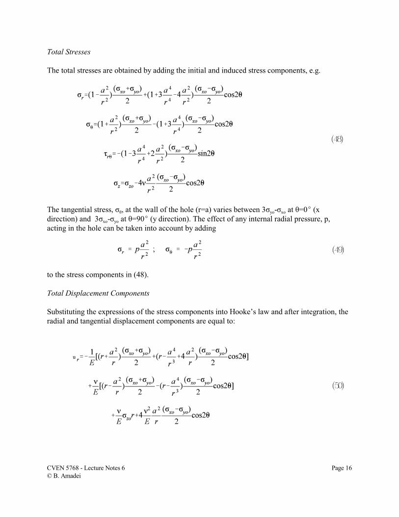
Total Stresses
The total stresses are obtained by adding the initial and induced stress components, e.g.
The tangential stress, óè, at the wall of the hole (r=a) varies between 3óyo-óxo at è=0E (xdirection) and 3óxo-óyo at è=90E (y direction). The effect of any internal radial pressure, p,acting in the hole can be taken into account by adding
to the stress components in (48).
Total Displacement Components
Substituting the expressions of the stress components into Hooke’s law and after integration, theradial and tangential displacement components are equal to:
CVEN 5768 - Lecture Notes 6 Page 16© B. Amadei
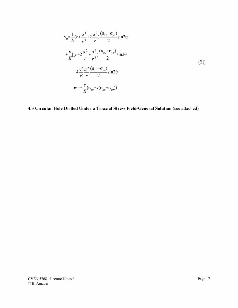
(51)
4.3 Circular Hole Drilled Under a Triaxial Stress Field-General Solution (see attached)
CVEN 5768 - Lecture Notes 6 Page 17© B. Amadei
5. USING STRESSES IN ROCK ENGINEERING
Rock masses are initially stressed in their natural state. Whether one is interested in naturalgeological structures (folds, faults, intrusions, etc..) or man-made structures (tunnels, caverns,mines, surface excavations, etc..), a knowledge of the in situ or virgin stress field (along withother rock mass properties) is needed when predicting the response of rock masses to thedisturbance associated with those structures. The response can take multiple forms such asdeformations of the walls of a surface or underground excavation, stresses and breakouts in thewalls of a shaft or borehole, creep of a salt pillar, initiation of a micro-earthquake, shearing of afault, glacial rebound of a glaciated terrain, etc.. Today, there exists a variety of analyticalsolutions to many of the geological, geophysical, and geoengineering problems. Computer-basednumerical methods for stress, strain, and strength analysis are also available to handle problemswith more complex geometries and/or constitutive behavior. Many of the analytical methods andnumerical codes use stress (or traction) as a possible boundary condition. Hence, a properdetermination, or at least a good estimation of the state of stress in situ is needed in order toreach reliable solutions to the problem of interest. In situ stresses play a critical role in civil engineering projects involving rock either as aconstruction or foundation material. They enter into the design and stability analysis of variousunderground structures (tunnels, caverns, shafts, etc..). They are also important when selectingthe location of pressure tunnels and shafts and other rock cavities used for hydropower orunderground storage of compressed natural gas, liquified natural gas (LNG), liquified petroleumgases (LPG), compressed air, oil or water, for which rock confinement is critical. Finally, in situstresses may control the stability of surface excavations (natural and man-made). The discussionbelow is limited to the role of in situ stresses in the behavior of underground excavations in rock.
Various stability problems may arise when opening an underground excavation in rock. Hoekand Brown (1980a) defined four major modes of instability: instability due to rock stresses,instability due to adverse structural geology, instability due to weathering and or swelling, andinstability due to excessive groundwater pressure or flow. They also noted that there aresituations where two or more failure modes could co-exist. The pre-excavation in situ stressesand their redistribution following excavation contribute to the first mode of instability.
In situ stresses often contribute to the second mode of instability as they can enhance or reducethe role played by the rock fabric and geological structures such as foliations, joints, faults, etc..Compressive stresses provide confinement and therefore tend to lock or clamp the rock mass,thus reducing the effect of blocks, wedges or slabs that would otherwise become unstable bysliding along discontinuities. Block stability is increased further if the discontinuities are roughand are not (or partially) free to dilate. On the other hand, tensile stresses may open fractures,accelerate the weathering, and create more stability problems. Finally, in situ stresses affectwater flow since compressive stresses make the rock mass tighter and less likely to createseepage problems upon excavation and thereafter.
CVEN 5768 - Lecture Notes 6 Page 18© B. Amadei
In situ stresses are mostly included in the analytical/numerical approach of the design ofunderground excavations. In the empirical approach, which is based on rock massclassifications, in situ stresses are "subjectively" included in the form of scaling factors. Forinstance, in the Q-rating of Barton et al., in situ stresses are taken into account in the stressreduction factor (SRF). In the Geomechanics Classification of Bieniawski, the RMR rating isadjusted using a coefficient that varies between 0.6 and 1.2 depending if the user judges thestresses to be beneficial or detrimental.
In the analytical/numerical approach to design, stress analyses are usually carried out byconsidering a region of a rock mass subject to fixed boundary conditions such as tractions(stress) or displacements, or mixed boundary conditions. The stresses measured in situ are usedas boundary conditions. A variety of analytical solutions (mostly two-dimensional) are availableto determine stresses around openings of simple shapes, in homogeneous and continuous rockand subjected to uniform in situ stresses at infinity. Figure 1 shows the classical example ofstress redistribution around a circular opening in a vertically stressed elastic plate. Numericalmethods such as the Finite Element Method, the Boundary Element Methods, and the Discrete(Distinct) Element Methods can be used to handle problems with more complex (two- or three-dimensional) geometries and for rock masses with more complex constitutive behavior. Areview of the analytical and numerical methods used in rock mechanics can be found in Obertand Duvall (1967), Jaeger and Cook (1979), Hoek and Brown (1980a), and Pande et al. (1990),among others. Figure 2 shows, as an example, the results of a three-dimensional elastic stressanalysis for a power house cavern conducted by Sugawara et al. (1986) using a three-dimensional boundary element method.
Stress analyses are usually conducted to determine stress concentrations, and the type of stressconcentration (compression versus tension). Since rock masses are weak in tension, tensilestresses may open existing fractures or create new ones which could result in block stabilityproblems. On the other hand, the magnitude of compressive stresses in the walls of anexcavation may be large enough to overstress the rock and mobilize the rock mass strengthlocally or not. This can result in problems such as rock bursts, spalling, buckling and heaving ofrock layers, squeezing and excessive deformation in the form of roof closure, sidewallmovement and/or ground subsidence. The location, extent and nature of the overstressed zonesdepend on many parameters such as rock mass properties (strength, deformability), the rockfabric (anisotropy, joints, etc..), the in situ stress field (magnitude and orientation), the geometryand depth of the excavation, and external conditions such as the topography, and the method ofexcavation. High horizontal stresses are likely to create problems in the roof and floor of anunderground opening whereas high vertical stresses are likely to create problems in its sidewalls.In mountainous areas with extreme topography and steep valley walls (such as in Norwegianfjords), tunnels parallel to the valleys have been found to experience rock bursts in the tunnelwall and in part of their roof located the closest to the valley side due to stress concentrations. Invery deep excavations such as the deep mines in South Africa and North America, stabilityproblems can occur all around the excavations. There are also situations where floor and roofstability problems along a section of an underground opening are replaced by sidewalls problems
CVEN 5768 - Lecture Notes 6 Page 19© B. Amadei
(or no stability problems whatsoever) along other sections.
As an example, Figure 3 shows the results of a two-dimensional stress analysis conducted byEissa (1980) using the boundary element method. The extent of the potential overstressed zonearound a horseshoe opening in a biaxial stress field with a vertical component, p, and ahorizontal component, 0.5p, was determined for different values of the ratio between the verticalstress, p, and the intact rock compressive strength, óc. The rock mass was assumed to be underplane strain and its strength was defined using the criterion proposed by Hoek and Brown(1980b) with two parameters, m and s. Three rock masses of decreasing strength wereconsidered and are defined as A, B and C. Figure 3 shows clearly an increase in the extent of theoverstressed zone around the opening as the rock mass strength decreases. Also, for given valuesof the parameters m and s, the extent of the overstressed zone increases with the ratio p/óc.
The value of the ratio between the vertical stress and the unconfined compressive strength of theintact rock material is critical when assessing the potential for squeezing of weak clay-bearingrocks such as shales, claystones, mudstones, etc.. A good example, described by Morton andProvost (1980), is that of the Stillwater tunnel in the U.S. where squeezing ground wasencountered in shale beneath ground cover of the order of 2,500 ft (762 m), resulting in acomplete stoppage of a Tunnel Boring Machine. In this case, the vertical stress to unconfinedcompressive strength ratio was of the order of 0.25.
Stress analysis can be used to determine the extent of the zone where stresses have beendisturbed by excavation of an underground opening. Such an analysis is important whenpredicting the interaction between adjacent openings and the interaction between an opening andadjacent geological structures such as faults. Eissa (1980) analyzed the stress distribution aroundopenings of various shapes and under different levels of horizontal and vertical stresses. Heconcluded that the zone of influence of an opening depends largely on its height to width ratioand the horizontal to vertical in situ stress ratio. For all practical purposes, stress redistributiontakes place over a distance from the wall of the opening of at least one to 1.5 times the openingspan. This rule of thumb seems to be realistic when compared to actual stress measurementsaround openings.
Figure 4 shows an illustrative example of stress redistribution measured by Obara et al. (1995) inJapan using the conical-shaped borehole overcoring technique. A total of 18 overcoring stressmeasurements were carried out at distances ranging between 0.6 and 29.5 m from the wall of a 6m span gallery excavated in granodiorite at a depth of 520 m. Three steeply dipping sub-parallelfaults were found to interact with the gallery; two intersecting the gallery itself (not shown inFigure 4) and one between measurements 6 and 7. Figures 4a and 4b show the distribution of theprincipal stresses in the vertical plane and in the horizontal plane, respectively. Here, the stressdistribution is affected by both the presence of the gallery and the fault(s). The stressmeasurements at points 17 and 18 (located more than 25 m from the gallery and 20 m from thefault) were taken as in situ stress values.
CVEN 5768 - Lecture Notes 6 Page 20© B. Amadei
Stress analysis can also help in the selection and design of support systems. For instance, theextent of overstressed rock can be used to determine the length of rock bolts. In situ stresses arean integral part of the ground-support interaction model proposed by Brown et al. (1983) sincethey form the "loading system". In this model, the extent of the plastic zone around anunderground excavation and the displacement of the walls of the opening depend on themagnitude of the in situ stresses. As the shape of the ground reaction curve varies with the levelof applied stress, so is the amount of support required to reach mechanical equilibrium betweenthe support system and the rock mass.
The distribution and magnitude of in situ stresses affect the geometry, shape, dimensioning,excavation sequence and orientation of underground excavations. The main goal when designingunderground openings in rock (where stresses are likely to be a problem), is to minimize stressconcentrations, create a compressive stress field as evenly distributed as possible ("harmonic"hole concept) in the excavation walls, and avoid tensile stress regions. This can be done bychanging the shape and geometry of the openings as well as their orientation with respect to theknown principal in situ stresses. The theory of elasticity is often used to that effect. However, asnoted by Hoek and Brown (1980a), the "harmonic" hole concept applies when virgin stresses arelow compared to the rock strength. If the virgin stresses are high enough, the harmonic holeconcept could result in uniform but large compressive stresses all around the opening whichcould create stability problems. In that case, Hoek and Brown (1980a) suggested following arecommendation proposed earlier by Fairhurst (1968) whereby the excavation shape is selectedin such a way that the zones of overstressed rock are concentrated in sharp corners, and arelimited in extent. According to Broch (1993), the same recommendation should be followed fordeep caverns where the in situ stresses are so high that rock bursts and spalling can be expected.
Stress concentrations based on the two-dimensional theory of elasticity are available for singleopenings in a uniform in situ stress field, or in a stress field increasing linearly with depth. Stressconcentration factors are also available for parallel openings of various shapes and for differentvalues of the opening span to pillar width ratio (Hoek and Brown, 1980a; Eissa, 1980). Figure 5shows a summary of tangential stress concentrations in the roof and spring-line of singleopenings in a uniform in situ stress field with vertical component p and horizontal componentkp. The rock is assumed to be homogeneous, continuous, and linearly elastic. This figureindicates that within the context of linear elasticity, openings with a major horizontal axis arebetter suited in stress fields with horizontal stresses higher than the vertical stress. On the otherhand, their major axis should be vertical if the vertical stress is larger. The ratio between themajor and minor axes of the openings should be of the same order as the horizontal to vertical insitu stress ratio. A general characteristic of stress concentrations around openings in isotropicmedia is that they are independent on the elastic properties of the medium. The reader should beaware that this is no longer true if the medium is anisotropic, in which case the stressconcentrations depend not only on the rock elastic properties but also on the orientation of theplanes of rock anisotropy with respect to the opening (Amadei, 1983). In general, stressconcentrations in layered rocks can be quite different from those in isotropic rocks.
CVEN 5768 - Lecture Notes 6 Page 21© B. Amadei
Stress concentrations around single or multiple underground openings can also be (qualitatively)inferred using the stream flow analogy proposed by Hoek and Brown (1980a) for elastic models.The idea is that the applied stress field is analogous to an undisturbed stream flow. In the wall ofan excavation (equivalent to a pier in the stream flow), zones of tension may develop and areequivalent to a separation of the stream lines. On the other hand, the zones of compressioncorrespond to a crowding of the stream lines. The stream flow analogy can be useful when tryingto understand the overall stress pattern around multiple excavations, and stress shadow effectsthat occur when excavations are in the near vicinity to each other.
The orientation of in situ stresses with respect to an excavation can have a large effect on theexcavation stability. The excavation layout should be optimized in order to minimize the impactof in situ stresses. Geological structures or any other constraints (topography, water, etc..) needalso to be taken into account in the optimization process.
The stability of rock caverns is very much controlled by their orientation with respect to the insitu stress field, along with other factors (Broch, 1993). In general, aligning caverns in rockswith their long axis perpendicular to the largest horizontal in situ stress component should beavoided. Excellent case studies showing the decisive role of in situ stresses on cavern orientationselection can be found in the literature. Figures 6a and 6b show strength/stress contours around aproposed powerhouse cavern in the Niagara Falls area (Haimson et al., 1986). In this example,the rock is horizontally stratified and the maximum and minimum horizontal in situ stresses arethe major and intermediate principal stresses. The stresses around the cavern were determinedusing the finite element analysis and the strength was defined using the empirical Hoek andBrown (1980b) failure criterion. Figures 6a and 6b differ in the orientation of the cavern withrespect to the horizontal stresses. In Figure 6a, the long axis of the opening is perpendicular tothe maximum horizontal stress óH=9.2 MPa. This results in large overstressed zones in the walland floor of the opening. On the other hand, in Figure 6b, the long axis of the opening is parallelto the maximum horizontal stress óH=9.2 MPa and perpendicular to the minimum horizontalstress óh=6.0 MPa. For that orientation, the size of the predicted overstressed zone is reducedconsiderably.
It is usually accepted that stress related instability problems increase with depth and thatstructurally controlled problems are more likely to occur at shallow depths. There are manyexceptions to that trend in particular in regions where high horizontal in situ stresses exist atshallow depths. This is the case near lake Ontario (southern Ontario and upper New York state)where stresses of the order of 5-15 MPa have been measured at shallow depths and where stressrelief phenomena such as heave of canal and quarry floors, natural pop-ups, rock squeeze, rockbursts, tunnel wall spalling, cracking of tunnel concrete linings, and/or movement of the walls ofunsupported excavations (tunnels, shafts, canals) have been observed (Franklin and Hungr,1978). Rock squeeze applies additional loads to surface and underground structures which maypresent considerable difficulties in maintaining operations. It is noteworthy that many of theproblems observed near Lake Ontario in Canada and in the U.S. have also been observed inhighly horizontally stressed sedimentary Post Permian rocks in the Sydney basin in Australia.
CVEN 5768 - Lecture Notes 6 Page 22© B. Amadei
Other examples where high horizontal in situ stresses have played a significant role in thestability of civil (and mining) engineering excavations have been reported for variousunderground works in Norway and Sweden.
In high horizontal stress fields, stress induced instability problems are likely to occur in the roofand floor of excavations in the form of spalling or squeezing due to high stress concentrations.As shown in Figure 5, for the simple case of a circular opening, the maximum tangential stressin the roof and floor of the opening is about three times the horizontal stress if the vertical stressis insignificant. If the opening is close to the surface, the stress concentrations in the roof andfloor are no longer equal and depend on the rock cover. For a rock cover equal to 10% of thetunnel diameter, the stress concentration in the roof is about seven times the horizontal stress.Hanssen and Myrvang (1986) reported several examples of N-S running tunnels in the Kobbelvarea in northern Norway experiencing heavy spalling in their roofs and floors as they weredriven perpendicular to the E-W trending major in situ stress component.
If the rock is bedded, layered or stratified, the effect of high horizontal in situ stresses will beenhanced and will be expressed in the form of buckling and heaving of roof and floor layers,respectively. Slip along layers may also create large inward and horizontal displacements of thetunnel sidewalls. Several case studies showing this phenomenon were described by Franklin andHungr (1978) for some tunnels in sedimentary rocks in southern Ontario. Guertin and Flanagan(1979) reported several cases of tunnel problems following excavation of tunnels at shallowdepths (1-7 m) in a highly stressed (up to 14 MPa) undeformed dolostone in Rochester, NewYork. Horizontal displacements as large as 40 mm were measured at the tunnel springline,whereas the crown experienced a heave of 0.4 mm. The displacements were accompanied withinvert and crown spalling (due to high tangential compressive stresses), and cracking at thespring line (due to tangential tensile stresses). All these case studies revealed, among otherthings, that in stratified rock masses, the roof and floor stability problems may not necessarily bethe same due to differences in rock layer stiffness and strength.
In general, the presence of high horizontal stresses at any depth should be clearly defined andproperly taken into account in the planning, design and construction of all major rockengineering projects. Failure to anticipate the existence of high stresses may result in structuraldamage and expensive remedial work as most design methods based on gravitational loadingonly are invalidated in that case (Franklin and Hungr, 1978). High horizontal stresses may alsocreate problems during excavation. Myrvang (1993) noted several case studies showing thedifficulties associated with Tunnel Boring Machine boring in a rock with violent surfacespalling.
Different strategies can be followed to minimize the impact of high horizontal in situ stresses.Franklin and Hungr (1978) recommended delaying tunnel lining following excavation. They alsosuggested maximizing the distance between the location of rock excavation and the nearest rigidsupport by over-excavation. Linings and supports should either be flexible enough or should beprotected by a deformable interface capable of accommodating up to 10 cm of movement of the
CVEN 5768 - Lecture Notes 6 Page 23© B. Amadei
excavation walls. Monitoring of displacements and rock pressures are also highly recommended.It has also been found that spalling and overbreak in the crown of tunnels can be successfullycontrolled by using rock bolting with or without shotcrete. In mining, the impact of high groundstresses can be minimized by playing with mining sequence and controlled yielding of pillarsand closing of excavations.
It must be kept in mind that high horizontal stresses may be beneficial in making the rocktighter, self supporting and less inclined to create seepage problems. Pathways for contaminanttransports are also smaller. In some cases, high horizontal stresses may permit the use of large(mostly unsupported) roof spans in underground caverns, a recent example being the 61 m spanunderground olympic ice hockey hall in Lillehammer, Norway (Myrvang, 1993).
It is noteworthy that the effect of in situ stresses on the stability of underground openings mayvary with time. Stress changes around underground openings may be associated with rock creep,nearby excavations, sequences of excavation, pumping, poor drainage, earthquake loading,blasting, etc..
6. REFERENCES
Amadei, B. (1983) Rock Anisotropy and the Theory of Stress Measurements, Lecture Notes inEngineering, Springer Verlag.
Broch, E. (1993) General report: caverns including civil defense shelters, in Proc. 7th Cong. Int.Soc. Rock Mech.(ISRM), Aachen, Balkema, Rotterdam, Vol. 3, 1613-1623.
Brown, E.T., et al. (1983) Ground response curve for rock tunnels. ASCE J. Geotech. Eng. Div.,109, 15-39.
Eissa, E.A. (1980) Stress analysis of underground excavations in isotropic and stratified rockusing the boundary element method. PhD Thesis, Imperial College, London.
Fairhurst, C. (1968) Methods of determining in-situ rock stresses at great depths. Tech. ReportNo. 1-68, Corps of Engineers, Omaha, Nebraska.
Franklin, J.A. and Hungr, O. (1978) Rock stresses in Canada: their relevance to engineeringprojects. Rock Mechanics, Suppl. 6, 25-46.
Guertin, J.D. and Flanagan, R.F. (1979) Construction behavior of a shallow tunnel in highlystressed sedimentary rock, in Proc. 4th Cong. Int. Soc. Rock Mech.(ISRM), Montreux, Balkema,Rotterdam, Vol. 2, 181-188.
CVEN 5768 - Lecture Notes 6 Page 24© B. Amadei
Haimson, B.C., Lee, C.F. and Huang, J.H.S. (1986) High horizontal stresses at Niagara Falls,their measurement, and the design of a new hydroelectric plant, in Proc. Int. Symp. on RockStress and Rock Stress Measurements, Stockholm, Centek Publ., Luleå, 615-624.
Hanssen, T.H. and Myrvang, A. (1986) Rock stresses and rock stress effects in the Kobbelv area,northern Norway, in Proc. Int. Symp. on Rock Stress and Rock Stress Measurements, Stockholm,Centek Publ., Luleå, 625-634.
Hoek, E and Brown, E. T. (1980a) Underground Excavations in Rock, Institution of Mining andMetallurgy, London.
Hoek, E. and Brown, E.T. (1980b) Empirical strength criterion for rock masses. ASCE J.Geotech. Eng., 106, 1013-1035.
Jaeger, J.C. and Cook, N.G.W. (1979) Fundamentals of Rock Mechanics, 3rd. Ed. Chapman &Hall, London
Lekhnitskii S.G. (1977) Theory of Elasticity of an Anisotropic Body, Mir Publishers, Moscow.
Morton, J.D. and Provost, A.J. (1980) Stillwater tunnel: a classroom in engineering geology, inProc. 13th Can. Rock Mech. Symp., Toronto, Canadian Institute of Mining and Metallurgy, CIMSpecial Volume 22, 80-89.
Myrvang, A.M. (1993) Rock stress and rock stress problems in Norway, in Comprehensive RockEngineering (ed. J.A. Hudson), Pergamon Press, Oxford, Chapter 18, Vol. 3, 461-471.
Obara, Y., et al. (1995) Measurement of stress distribution around fault and considerations, inProc. 2nd Int. Conf. on the Mechanics of Jointed and Faulted Rock, Vienna, Balkema,Rotterdam, 495-500.
Obert, L. and Duvall, W.I. (1967) Rock Mechanics and the Design of Structures in Rocks, Wiley,New York.
Pande, G.N., Beer, G. and Williams, J.R. (1990) Numerical Methods in Rock Mechanics, Wiley,London.
Poulos and Davis (1974) Elastic Solutions for Soil and Rock Mechanics, Wiley, New York.
Sugawara, K., et al. (1986) Determination of the state of stress in rock by the measurement ofstrains on the hemispherical borehole bottom, in Proc. Int. Symp. on Large Rock Caverns,Helsinki, Pergamon Press, Oxford, Vol. 2, 1039-1050.
Timoshenko, S.P. and Goodier, J.N. (1970) Theory of Elasticity, McGraw-Hill.
CVEN 5768 - Lecture Notes 6 Page 25© B. Amadei