Embed Size (px)
Citation preview

APPLICATIONS OF DSP
LECTURE 5 5-1
Encoding of WaveformsEncoding of Waveforms to Compress Information
DataSpeechImage
Encoding of Speech Signals – VocodersMakes use of special properties of speech
PeriodicityDistinction between voiced and unvoiced sounds
Image EncodingMakes use of suitable transformsUses special techniques
Transmits only the difference between image frames
Combines speech and image coding for video
• Encoding of Waveforms Information forms a very important part of modern life. For information to be useful, it must be available where and when it is needed. This means that we need to send vast amounts of data over communication networks and store it when it is received. Communication channels in every form and shape have now become a necessity for our information needs. Similarly, storage media are needed to keep the information accessible. The need for these elements: storage media and communication channels, increases steadily and usually at a faster rate than the technology can offer at a reasonable price. For example, two decades ago, 1MB of disk storage capacity for personal computers was seen as a reasonable size. Today, a full gigabyte may not be sufficient. The price for storage media may be reduced in actual bytes per dollar, but with our increasing needs for more information and communication channel capacity, storage media will always be at a premium, despite the lowering of costs. It is therefore important that we use them as efficiently as possible. We shall examine waveform, speech, and image encoding techniques that enable us to compress data efficiently. There are two principle types of compression schemes − lossy and lossless. Lossless schemes do not lose any information. With these schemes it is possible to uncompress the data a retrieve the original uncompressed information. A common examples of lossless compression are .zip and .gif files used on computers.
5-1
Lossy encoders, on the other hand, have a completely different philosophy. They aim to encode the data such that only the most important segments of information are preserved. Segments that do not effect the quality of the output in a significant way are ignored. The selection process aims to increase compression rates without a significant loss of quality. Clearly, each application will define the term significant loss of quality in a different way. For example, in some speech applications, acceptable levels of quality may be measured by understandability. The decompressed speech signal may not look anything like its original, but as long as it can be understood, it may be acceptable. Analog and digital waveform encoding techniques can be used to reduce the bandwidth of any data. These are lossless coding techniques.
• Speech Encoding Speech encoding makes use of special properties of speech signals to reduce the bandwidth requirements of speech signals. Most speech coders use the periodicity of voiced sounds and discard the parts of the signal that we cannot hear very well. We shall look at speech coders (vocoders) in more detail later in this chapter.
• Image Coding Image coders mostly use transforms, fractals, or wavelets to compress image data. They also employ special techniques for moving images that exploit the similarity between frames. Video images have associated sound. Most video image coders combine image and speech coders to effectively reduce the bandwidth of video signals. We will look at some image coding schemes that use transforms and encoders. These practical examples will introduce us to some of the terminology and techniques used in image coding. We will not be examining emerging fractals and wavelet techniques, but our introduction should serve as a good basis for understanding these techniques.
• Applications of DSP DSPs dominate the area of waveform, speech, and image coding. They are extremely suitable processors to implement filters, transforms, and many other signal-processing tasks. More importantly, they are flexible. When a more efficient coding scheme is discovered or a new coding standard is issued, DSPs can be used immediately for implementation.
5-2

LECTURE 5 5-2
Analog Waveform Encodingx(t)
t
t
t
t
PAM
PWM
PPM
Observe Original Signal
Amplitude of a train of pulses ismodulated:Pulse Amplitude ∝ Signal Amplitude
Width of a train of pulses ismodulated:Pulse Width ∝ Signal Amplitude
Position of a train of pulses ismodulated:Pulse Position ∝ Signal Amplitude
• Analog Waveform Coding There are three primary methods of analog waveform encoding:
• Pulse amplitude modulation (PAM) • Pulse width modulation (PWM) • Pulse position modulation (PPM)
Each uses a different property of the pulse to describe the changes in the analog waveform. These coding methods are examples of lossless coding. As long as an adequate sampling rate is maintained, the information content of the signal remains intact. As you will remember from our lecture on sampling, this is the “Nyquist Rate”. The analog signal should be sampled at least twice its highest frequency component.
• Pulse Amplitude Modulation The amplitudes of pulses are modulated with the incoming analog waveform. The amplitude of a pulse is proportional to the amplitude of the analog signal at that point in time. The frequency of the pulses must be at least twice the highest frequency of the analog signal. Pulse amplitude modulation is equivalent to periodic sampling and holding.
• Pulse Width Modulation The width of a train of pulses is modulated with the analog signal. The larger the amplitude of the modulating signal, the longer the pulse. When PWM pulses are received, the analog signal is regenerated in proportion to the width of the pulses. Again, the sampling rate must be at or above the Nyquist limit. PWM is used in DAC design.
5-3

• Pulse Position Modulation The positions of the pulses are proportional to the amplitudes of the modulating signal. Pulses move further away from their normal position depending on the amplitude of the modulating signal. The pulses do not move out of their time cells because this would violate the coding. Zero amplitude is indicated by the pulse staying in its original position. There is always a pulse present in a time cell, and there are no missing pulses. This makes the decoder design simpler.
5-4
LECTURE 5 5-3
Pulse Coded Modulation (PCM)
x(t)
t
t
PCMy(t)
1 0 0 1 1 01 1 01 1 1
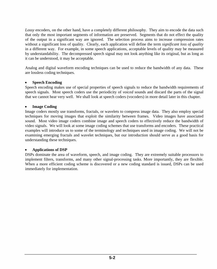
Pulse Coded ModulationSamples are digitized to n bits (thisexample uses 3 bits)Using more bits increases accuracyPCM has a significant DC componentModulating onto higher frequencycarrier reduces DC component
Other PCM SchemesDelta Modulation (DM)Differential PCM (DPCM)Adaptive DPCM (ADPCM)
Digital Waveform Coding
DSPs are ideal for implementing most PCM schemes
PCM = Any Analog to Digital conversion where the result is a serial bitstream. Several methods of converting and transmitting PCM exist.
• Pulse Coded Modulation - PCM Pulse coded modulation is one of the most common digital waveform encoding schemes. The analog signal is first digitized. This is raw PCM. This signal is then modulated onto a higher-frequency carrier or processed in another way to suit a particular application. The medium of transmission could be as simple as a piece of wire where the digital data is transferred digitally, a phone line where only voice band analog signal is allowed, or fiber optic cable. For example, in the case of a telephone line, which will only pass analog signals from 300-3000Hz, an amplitude or frequency modulation can be used to transmit and receive the bits. In fact, a modern modem uses a combination of modulation schemes to achieve higher bit rates. Our example shows digitization using three bits. If more bits are used to represent a single sample, the PCM system becomes more accurate. In its basic form, PCM contains a significant DC component, which makes it unsuitable for transmission over long distances. Usually, basic PCM output is modulated onto a higher-frequency carrier wave, reducing the total DC content of the signal to be transmitted. There are many variations of the basic PCM scheme:
5-5
• Delta modulation (DM) • Differential PCM (DPCM) • Adaptive DPCM (ADPCM)
These variations of PCM strive to achieve more efficient coding by using fewer bits to represent the signal without losing the original information. They are still lossless schemes.
• Implementation of Coding (Codecs) DSPs provide an excellent medium for implementing analog and digital waveform encoders, particularly for PCM schemes. Many PCM schemes require FIR and IIR filters, as well as other signal processing functions. Such requirements may be efficiently implemented using DSPs.
5-6

LECTURE 5 5-4
Speech Coding – Vocoders Speech vocoders exploit special properties of speech
Vocal Tract = Acoustic TubeVoiced sounds are periodic in nature, e.g., “A”, “E” soundsUnvoiced sounds are like random noise, e.g., “S”, “F” soundsAim for maximum possible compression
Understandable but not 100% faithful reproduction
A Typical Vocoder – Synthesis
RANDOMNOISE
VOCAL-TRACT
MODELERx
PERIODICEXCITATION
GAIN
SPEECH
TIME - VARYING FILTER
PITCH
The analog and digital waveform coding techniques we have explored until now are applicable to any group of signals or data. However, if we know some of the general properties of the signal that we are going to code, we may use these properties to our advantage and reduce the bandwidth requirements even further. For example, if a signal is periodic for a certain time, all we need to send across are sufficient samples from one period and the length of time that the signal is periodic. This information is sufficient to reproduce the original signal. By closely examining speech signals and image data, we can find properties that we can use to our advantage in their compression. Speech coders are usually lossy. They ignore spectral sections of speech signals that we cannot hear. They also try to estimate periodicity in certain speech segments. The result of decompression is usually quite surprising. Although the reproduced signal does not resemble the original on a scope, sometimes it is difficult to hear the difference between them.
• Speech Coding - Vocoders Speech is produced by excitation of an acoustic tube, called the vocal tract. Our vocal tract starts from the glottis and is terminated by our lips. Voiced sounds (e.g. “a” or “e”) are produced as a result of vibration of vocal cords, which generates semi-periodic pulses of airflow that excite the vocal tract. This is why voiced sounds in human speech are periodic in nature. Although a voiced sound may at first resemble a random noise, a sufficiently small sample will reveal its periodic nature. It is this pattern that vocoders try to extract and use to produce the digital representation of speech. The frequency of this pattern is usually referred to as the pitch of speech.
5-7

Unvoiced sounds (e.g. “s” or “f”) are produced by constricting the vocal tract and forcing air through the constricted area. Air traveling through the constricted area creates turbulence and produces a noise-like excitation. This is why unvoiced sound waveforms are very much like random noise. In fact random noise generators can be used to reproduce unvoiced sounds. These sources provide a wide-band excitation to the vocal tract. The vocal tract can be modeled as a slowly time-varying filter that imposes its frequency transmission properties upon the spectrum of the excitation. In the case of a digital filter, the coefficients of the filter would try to model the vocal tract parameters as closely as possible. Speech coders are named vocoders (voice coders). Vocoders map speech signals onto a mathematical model of the human vocal tract. Instead of transmitting efficiently quantized speech samples, voice encoders transmit model parameters. The decoder applies the received parameters to an identical mathematical model and generates an imitation of the original speech. The process of determining model parameters is called analysis and the process of generating speech from the chosen parameters is called synthesis. Vocoder sound quality varies greatly with the input signal because vocoders are based upon a vocal tract model. Signals from sources that do not fit the model may be coded poorly, resulting in lower-quality signal reproduction after decompression. Vocoders assume that the excitation sources and the vocal tract shape are relatively independent. The above block diagram shows such a vocoder. The time-varying filter models the vocal tract. However, the vocal tract changes shape rather slowly, so it is reasonable to assume that the filter is time-invariant for short periods of time (e.g. 12mS). Voiced sounds are produced by a periodic excitation upon which the spectral characteristics of the vocal tract modeler are imposed. Unvoiced sounds use a random noise generator as the source of the excitation, but the spectral characteristics of the vocal tract modeler are still imposed on them. Each time, the vocal tract modeler (the filter) may impose different spectral characteristics on the source of the excitation. To understand more about how vocoders work, we will look at the basic design of one of the earlier vocoders. This vocoder, called a channel vocoder, is still widely used today.
5-8
LECTURE 5 5-5
Channel Vocoder – Coder
Speech is split into subbands for spectral envelope detectionEnvelope detection aids vocal tract modeling
Pitch detector estimates the frequency and aids indistinguishing voiced and unvoiced segments
Outputs are multiplexed to produce coded speech signal
BANDPASSFILTER RECTIFIER LOWPASS
FILTER
BANDPASSFILTER RECTIFIER LOWPASS
FILTER
PITCH DETECTOR
SPEECH
IN
CODED
OUTPUTMUX
1
16ADC
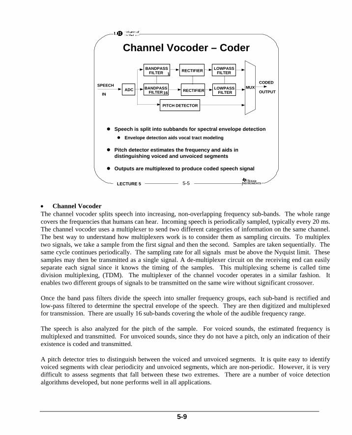
• Channel Vocoder The channel vocoder splits speech into increasing, non-overlapping frequency sub-bands. The whole range covers the frequencies that humans can hear. Incoming speech is periodically sampled, typically every 20 ms. The channel vocoder uses a multiplexer to send two different categories of information on the same channel. The best way to understand how multiplexers work is to consider them as sampling circuits. To multiplex two signals, we take a sample from the first signal and then the second. Samples are taken sequentially. The same cycle continues periodically. The sampling rate for all signals must be above the Nyquist limit. These samples may then be transmitted as a single signal. A de-multiplexer circuit on the receiving end can easily separate each signal since it knows the timing of the samples. This multiplexing scheme is called time division multiplexing, (TDM). The multiplexer of the channel vocoder operates in a similar fashion. It enables two different groups of signals to be transmitted on the same wire without significant crossover. Once the band pass filters divide the speech into smaller frequency groups, each sub-band is rectified and low-pass filtered to determine the spectral envelope of the speech. They are then digitized and multiplexed for transmission. There are usually 16 sub-bands covering the whole of the audible frequency range. The speech is also analyzed for the pitch of the sample. For voiced sounds, the estimated frequency is multiplexed and transmitted. For unvoiced sounds, since they do not have a pitch, only an indication of their existence is coded and transmitted. A pitch detector tries to distinguish between the voiced and unvoiced segments. It is quite easy to identify voiced segments with clear periodicity and unvoiced segments, which are non-periodic. However, it is very difficult to assess segments that fall between these two extremes. There are a number of voice detection algorithms developed, but none performs well in all applications.
5-9

In summary, the channel vocoder analyzes the incoming speech signal by three major categories: • Speech spectral signal envelope • Pitch • Amplitude
Extracted information is then multiplexed and transmitted. Such analysis does not look to preserve the originality of the speech, but tries to compress it without losing the ability to understand it.
5-10

LECTURE 5 5-6
Channel Vocoder - Synthesis
Pitch information switches between “Voiced - Pulse Source”and “Unvoiced - Random Noise” sounds
Pitch produces correct frequency for voiced sounds
DSP is the ideal medium for implementing vocodersFilters may be implemented efficientlySpeech spectrum can be analyzed easilyVocal tract can be modeled easily
+SPEECH
BANDPASSFILTERX
BANDPASSFILTERX
RANDOMNOISE
PULSESOURCE
PITCH
DE-MUX
CODED
INPUT
DAC
• Channel Vocoder - Synthesis The synthesizer reverses the coding process. First, the received signal is de-multiplexed to separate out the different information categories. The part of the signal carrying the spectral envelope information is then converted to analog. If it is from a voiced speech segment, estimated pitch frequency is used to fill in the spectral envelope. However, if it is from an unvoiced segment, the random noise generator is used to regenerate the sound. Finally, the signal segment is band pass filtered to its original frequency range. If we examine the block diagram of vocoders, it is quite apparent that most of the blocks can be implemented with contemporary DSPs. Filters are particularly easy to implement, and their processing time is well within the range required by speech signals. There are a number of pitch estimator algorithms already implemented using DSPs. The processing power of DSPs and their suitability for signal processing make it possible to implement efficient pitch estimators. Today, many vocoders, voice mail, auto-call answering, and routing systems use DSPs. We explained the basic operation of one of the earlier vocoder designs. There are a number of different vocoding systems using different signal processing techniques. These are rather specialized systems, and each has a particular application area. Hopefully, we have explained the basic foundations of speech coding well enough that the interested students can now explore these techniques further.
5-11

• Image Coding We have discussed coding analog, digital, and speech signals; however, when we speak of coding images, we must be particularly concerned with the requirements for storage space. With color images especially, storage requirements easily run into several megabytes. The primary reason for this is the sensitivity of our vision system. We can see a lot of detail and can detect minute changes in a picture. Therefore, for our vision system to have an impression of smooth movement, the image of a moving object must change its position at least 16 times a second. Otherwise, we can detect individual movements. This means that if we want to play an animated scene on our computer, we need 16 screens of images stored for just one second’s worth of movement. Transmitting this information over our existing telephone network would be a nightmare. To put the complexity of the problem into perspective, let us consider an example that we all know about: television.
• Bandwidth for Current TV (NTSC and PAL) In North America the NTSC television system is used, while in the UK the PAL system is used. The two systems are very similar, but they differ in line resolution and the way color information is modulated. The NTSC system has 525 lines and the PAL system has 625 lines. Not all of these lines are available for video information as some are used for synchronization. Both systems have a 4:3 aspect ratio and the have actual visible resolutions of 484 by 427 pixels (NTSC) and 580 by 425 pixels (PAL). The NTSC system has a frame
5-12
LECTURE 5 5-8
Bandwidth for TV
For black and white picture,bandwidth required isapproximately 3 MHz
Each pixel represents onesample so the requiredbandwidth is 6 MHz for ahorizontal resolution of 3 MHz
For color pictures, basic rate isabout 150 MBits per second
White Pixel
Black Pixel
3 MHz
3 6 MHz
A
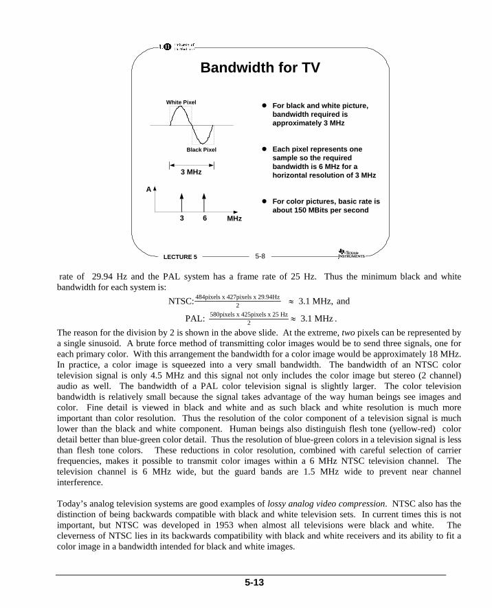
rate of 29.94 Hz and the PAL system has a frame rate of 25 Hz. Thus the minimum black and white bandwidth for each system is:
NTSC: 3.1 MHz, and484pixels x 427pixels x 29.94Hz2 ≈
PAL: 3.1 MHz580pixels x 425pixels x 25 Hz2 ≈ .
The reason for the division by 2 is shown in the above slide. At the extreme, two pixels can be represented by a single sinusoid. A brute force method of transmitting color images would be to send three signals, one for each primary color. With this arrangement the bandwidth for a color image would be approximately 18 MHz. In practice, a color image is squeezed into a very small bandwidth. The bandwidth of an NTSC color television signal is only 4.5 MHz and this signal not only includes the color image but stereo (2 channel) audio as well. The bandwidth of a PAL color television signal is slightly larger. The color television bandwidth is relatively small because the signal takes advantage of the way human beings see images and color. Fine detail is viewed in black and white and as such black and white resolution is much more important than color resolution. Thus the resolution of the color component of a television signal is much lower than the black and white component. Human beings also distinguish flesh tone (yellow-red) color detail better than blue-green color detail. Thus the resolution of blue-green colors in a television signal is less than flesh tone colors. These reductions in color resolution, combined with careful selection of carrier frequencies, makes it possible to transmit color images within a 6 MHz NTSC television channel. The television channel is 6 MHz wide, but the guard bands are 1.5 MHz wide to prevent near channel interference. Today’s analog television systems are good examples of lossy analog video compression. NTSC also has the distinction of being backwards compatible with black and white television sets. In current times this is not important, but NTSC was developed in 1953 when almost all televisions were black and white. The cleverness of NTSC lies in its backwards compatibility with black and white receivers and its ability to fit a color image in a bandwidth intended for black and white images.
5-13

• Digital TV Current television standards use analog processing. Let us consider the implications of processing images at today’s standards digitally. For digital processing, the image must be broken down into pixels (samples). For NTSC, the image resolution is 484 x 427 and the frame rate is 29.94 Hz. Thus, the pixel rate is
484 x 427 x 29.94 6.2 Mpixels / s≈ . For a strictly black and white image (only black or only white, no shades of gray), a single bit is needed for each pixel, thus the bit rate is the same as the pixel rate. For television, we are interested in more than just a black or white image. At a minimum, we want shades of gray, and more preferable, we want color. For computer displays, 8-bit color is a low cost, acceptable color coding. Each pixel is represented by eight bits. This allows for up to 256 different colors. Generally, 24-bit color is considered sufficient for images. In this coding, each pixel is represented by 24 bits. This allows for the representation of 16,777,216 different colors. Thus the bit rate for a 24 bit color image at NTSC resolution is
484 x 427 x 29.94 x 24 149 Mbits / s≈ . This bit rate represented exceeds the current NTSC image quality because there is absolutely no color compression. One of the benefits of digital TV (DTV) is supposed to be higher image resolution. A higher resolution involves a higher uncompressed image bandwidth. Fortunately, as with analog television, there are compression techniques that reduce the required bit rate by a substantial amount and make DTV possible.
5-14
LECTURE 5 5-9
Transform CodingTransform coding of images reduces bandwidth requirements
Most of the information in a picture is at low frequenciesTransform coders preserve information at low frequenciesIgnoring transformed signals with small coefficients
Reduces bandwidth requiredDoes not significantly degrade picture quality
FFT is not very useful because it produces imaginary components
Discrete cosine transform (DCT) is very popular in imageprocessing
Image is divided into 8x8 element blocks and each block is individuallytransformedA full-screen color image requires 200 Mbit/s channelBy using transforms and SPCM, the same image can be transmitted overa 34 Mbit/s channelThe resulting reduction is approximately 6 times
Huffman coding may be used on transformed signals to furtherreduce the bandwidth requirements
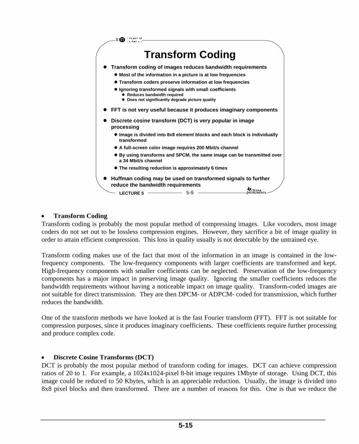
• Transform Coding Transform coding is probably the most popular method of compressing images. Like vocoders, most image coders do not set out to be lossless compression engines. However, they sacrifice a bit of image quality in order to attain efficient compression. This loss in quality usually is not detectable by the untrained eye. Transform coding makes use of the fact that most of the information in an image is contained in the low-frequency components. The low-frequency components with larger coefficients are transformed and kept. High-frequency components with smaller coefficients can be neglected. Preservation of the low-frequency components has a major impact in preserving image quality. Ignoring the smaller coefficients reduces the bandwidth requirements without having a noticeable impact on image quality. Transform-coded images are not suitable for direct transmission. They are then DPCM- or ADPCM- coded for transmission, which further reduces the bandwidth. One of the transform methods we have looked at is the fast Fourier transform (FFT). FFT is not suitable for compression purposes, since it produces imaginary coefficients. These coefficients require further processing and produce complex code.
• Discrete Cosine Transforms (DCT) DCT is probably the most popular method of transform coding for images. DCT can achieve compression ratios of 20 to 1. For example, a 1024x1024-pixel 8-bit image requires 1Mbyte of storage. Using DCT, this image could be reduced to 50 Kbytes, which is an appreciable reduction. Usually, the image is divided into 8x8 pixel blocks and then transformed. There are a number of reasons for this. One is that we reduce the
5-15
complexity of DCT calculations. By dividing the image into blocks, we can transform them in an amount of time that is acceptable for real-time image processing. The second reason for dividing the image into blocks is that by doing so, we can exploit redundancy in our coding if we find similar areas in the image. To put it even more simply, if the transform of a block is very similar to the next block, there is no need to transmit both, since just one should be sufficient. Finally, by dividing the image into blocks, we could use gradual image build-up on the receiving end. This particular feature is very useful on the Internet and with videophones. Continuing with our TV example, a full-screen color image requires 200M bits/s channel bandwidth. Using a combination of DCT and DPCM, the bandwidth requirements could be reduced to 34M bits/s, a reduction of about 6 to 1.
• Huffman Coding Huffman Coding is a type of entropy coding that basically relies on the fact that all outputs do not occur with the same probability. Outputs that occur frequently use shorter codes. Infrequent outputs use longer codes. The overall effect of this coding is that the bandwidth of the original signal is reduced quite dramatically.
5-16

LECTURE 5 5-10
Video Compression
H Series standards are most popular for video compression
H.261 and H.320 standards describe compression algorithms
H Series Coding:The difference between present and previous frames is transformedwith DCT, Huffman coded and transmittedMotion detector produces displacement vectors indicating directionand displacement of movement between previous and present frame
VIDEO INDCT HUFFMAN
CODERΣ
MOTIONDETECTOR
PREVIOUSFRAMESTORE
COEFFICIENTVALUES
DISPLACEMENTVECTORS
+
–
IMAGEREGENERATION
PRESENT FRAME
Simplified Diagram of H.261 Coder
• Practical Image Compression Image compression is widely used in videophones, still pictures, and transmission of full-motion images. It is efficient compression algorithms that make image storage and transmission possible. Videophones and videoconferencing are now moving from specialized applications towards mass markets and public use. Most personal computers can now store and retrieve color images. Even full-motion video is becoming very common in many applications. Three dominant standards are now emerging for image compression and coding that have found widespread use in industry.
• H-series standards for video compression (H.216, H.320) • JPEG for still pictures • MPEG for full-motion images
These standards are updated quite often as new image coding algorithms prove their efficiency. Sometimes standards also move out of their domain. For example, although JPEG is primarily for still pictures, it is used in video, animation and similar applications where moving images are involved. We shall briefly look at current versions of these standards.
• Video Compression H-series recommendations are the CCITT (the consultative Committee for International Telegraph and Telecommunication) standard. Since their start in late 1970s, the standards found increasing compliance from mostly European and later from US- and Japanese-based manufacturers. The current standards (H.261) and the more recent version (H.320), are designed to allow transmission at multiples of 64K bits/s (p x 64K bits/s), which is the lowest frequency that can be used on narrow band ISDN (Integrated Services Digital
5-17

Network). ISDN is a new class of service offered in Europe by telecommunications companies. It is very much like a super telephone service. The line comes to your office and the basic channel carries 16 times more data than a standard telephone line. In essence, H-series standards exploit the similarity between video frames. Each new frame is compared with the previous one and only the differences are coded and transmitted. Although the actual compression process is a little bit more complex, the philosophy of the scheme relies on the similarity between frames. It is presumed that videophones and videoconferencing systems have images with chunks of materials, rather than a lot of little bits and pieces. The image will typically consist of a human head or a number of heads with some background material. The head will generally be the only object that moves on the screen, and not very fast at that. Once all of the information in the scene is transmitted, we can probably get away by with transmitting the direction and amount of movement of the head. H.320 is the latest revision to H-series standards. H.261 is an earlier standard that found its way into many designs. Both standards use a combination of DCT and Huffman coding techniques. The block diagram on the slide shows a simplified H.261 coder. The difference between the present and previous frame is first transformed using DCT, and then Huffman-encoded coefficients are transmitted. The same coefficients are used in regeneration of the previous frame. The motion detector compares the previous and present frames block-by-block, looking the direction and the amount of movement between the two frames. The motion detector then codes the movements into displacement vectors, which are subsequently transmitted.
5-18

LECTURE 5 5-11
Video Decompression
DECODED PICTURE
COEFFICIENTVALUES
DISPLACEMENTVECTORS
++
IDCT
FRAMESTORE Σ
Simplified Block Diagram of H.261 Decoder
H Series standards allow manufacturers to design for differentapplications with different performance levels
Videoconferencing systemsVideophones
H.261 and more recent H.320 standards are computationallyintensive
DSPs provide the best implementation platform
• Video Decompression The block diagram above shows a simplified H.261 decoder. Coefficient values are inverse-transformed and added to the previous frame, which is adjusted using displacement vectors. The decoded picture is usually of good quality. The main problem in video transmission systems today is jerky pictures, which is primarily due to limited channel bandwidth. The transmitter cannot transmit a sufficient number of frames in time to achieve smooth movements. The H.261 standard tries to eliminate this jerkiness by efficiently compressing the video frames such that even with limited bandwidth, we could achieve a reasonable quality of movement.
• H Series Standards H.261 and H.320 standards are flexible in this use of transmission rates and applications. For example, ISDN capability may be used in multiples of 64K/ bits, which allows manufacturers to design equipment such as videophones and videoconferencing with differing capabilities, (i.e., some video phones use small screens that require lower bit-rates while a video conferencing system with larger screens requires very high bit-rates).
• Video Compression Implementation As we have seen, H-series standards require DCT, Huffman coding, motion estimation, and many of other signal processing functions. DSPs are well equipped to perform these functions. However, in a real-time environment such as videoconferencing, most of the functions need to be completed in a limited time. Such applications also require more processing to handle communications. For example, a videoconferencing system on ISDN would need to handle all communication overheads, including formatting the signal for transmission. Videoconferencing and videophone systems require a special sort of DSP − one with all of the
5-19

properties of standard DSPs, and a lot more processing power. Current approaches involve placing multiple DSPs, along with specialized hardware for video applications, on the same silicon.
5-20

LECTURE 5 5-12
Joint Photographic ExpertGroup - JPEG
COEFFICIENTCODERDCT HUFFMAN
CODERQUANTIZERPICTURE ENCODED
DATA
IDCTINVERSEQUANTIZER
COEFFICIENTDECODER
HUFFMANDECODER
DECODED
PICTURE
ENCODEDDATA
Picture is transform-coded by DCT in 8x8 blocksCoefficients are quantized
More bits are used for lower frequencies ensuring greateraccuracy for higher information content
Next stage codes and orders coefficientsFinally, coefficients are Huffman encoded to reduce amount ofdata
JPEG decoder reverses the coding process to produce a stillpicture
• Joint Photographic Expert Group (JPEG) Standard Compression The Joint Photographic Expert Group’s proposed standard is aimed at still-picture compression. In many ways, it is similar to H-series coding, but does not concern itself with the movement of images. Under JPEG, each color component of a picture is transformed using DCT in blocks of 8x8. The transform coefficients are then quantized. The number of bits used in quantization is frequency-dependent. The more important low-frequency components are assigned more bits, while high-frequency components are quantized using fewer bits. The whole stream is then ordered in a fashion suitable for Huffman coding. Bandwidth requirements are reduced further by Huffman coding. The encoded data is then ready for transmission or storage. The main difference between this and H- series coding is that JPEG does not use motion detection estimators. However it is possible to code moving images with JPEG by compressing each frame independently. There is ongoing research to identify applications where each compression scheme would be more efficient. The JPEG decoder reverses the coding process, and implementation of the JPEG decoder is more complex than the coder. JPEG compression is widely used today. There are a number of dedicated chips that implement the current version of the JPEG standard in hardware. There are also a number of JPEG algorithms implemented to execute on DSPs. The advantage of implementing JPEG using DSPs is that when the standards change, implementation of the new standard can be done much quicker than any other method. Such implementations are currently in use, and accelerate the operation of software packages such as Adobe Photoshop.
5-21

LECTURE 5 5-13
Moving Pictures ExpertGroup - MPEG
Each frame is split into small blocks
Blocks are transform-coded by DCT
Coefficients are coded with one of the following:Forward or Backward predictive codingor a combination of both
This scheme makes use of the similarity between the presentframe and either the previous or the next frame
Finally, blocks are quantized for transmission
QUANTIZEDCT HUFFMANCODER
FORWARD/BACKWARDPREDICTIVE
CODING
MOVINGPICTURE
ENCODEDDATA
MPEG coding is similar to H Series (H.320) and JPEG standards
It is primarily aimed at digital storage media such as CD-ROM
• Moving Pictures Expert Group (MPEG) Standard Compression MPEG compression is primarily aimed at full-motion image compression on digital storage media such as CD-ROM. The operation of MPEG is very similar to H series and JPEG compression. The primary difference is that MPEG takes the use of inter-frame dependency a step further. MPEG checks the similarity between the present frame and the next frame, but also check the previous frame. This is arguably a more effective method than H.261 in compressing moving images. Certainly, it is twice as effective as JPEG for compressing moving images. However, MPEG codecs (coders / decoders) are more complex than JPEG codecs.
• How Does MPEG Work? The color element of each frame is divided into 8x8 blocks, and each block is transformed by DCT. Coefficients are then coded with forward or backward predictive coding, or a combination of both. All three coding methods exploit the similarity between previous and next frames. Finally, the blocks are quantized and transmitted. Similar to JPEGs, there are a number of dedicated chips and algorithms for DSPs that implement current MPEG standard (MPEG 2.0).
5-22