Embed Size (px)
Citation preview

Applications of DSP in DC Drives RV Machines and AC Drives SPIM Machines
Narin Watanakul Department of Electrical and Computer Engineering, Faculty of Engineering,
Thammasat University, Rang sit Campus, Klong Luang, Pathumthani, Thailand. E-mail: [email protected]
Abstract— The specific requirements for data acquisition, processing, and control in the studied electrical drive for Digital signal processing (DSP), the cornerstone of numerous applications that power electronics and the development of high-performance drives is one of them, for example, drives. The designed controller for dc and ac drives using DSP TMS320F28335. The controlled with current and speed controller is designed and implemented using MATLAB/SIMULINK program, that is the current and speed response is verified through simulations and experiments. The paper is proposed solution is developed for the case of two part types, that first part of study to the DC drives for roof ventilator (RV) is a diameter about 75 cm, the RV will be direct coupling into dc machines, a new power conversion on machinery with roof ventilator (RV) dc machines at maximum rated dc voltage 24V, 117W. The DC motor operation mode it can control variable speed on rang 0-800 rpm. And the second part, proposed to study to the AC drives for the Single-phase induction motor (SPIM) is transformed from a non-linear to linear control plant, at maximum rated 3hp (2.2kW) 220V 50Hz. The indirect rotor field-oriented control (IRFOC). The SPIM operation mode it can control variable speed on rang 0-1000 rpm. In this paper that is is a review of DSP applications that provides a guideline to further analyses and improve power conversion in electrical system pertinent to DC and AC drives technique.
Keywords: Digital signal processing (DSP), Renewable Energy, Roof Ventilator (RV), Wind Turbine, DC machines, single-phase induction motor (SPIM), Capacitor motor, Indirect rotor field-oriented control (IRFOC).
I. INTRODUCTION DC DRIVES FOR ROOF VENTILATOR (RV)
Thailand Meteorological Department (Bangkok) and for the river mouth Pilot Station, monthly mean wind speeds taken from climatological data 1966 – 1995 are reported below Pilot Station: 3.4 – 5.6 m/s of a report in (e.g., DEDP., 2001), [1]. In Fig.1, the ventilators are also designed in a way that prevents leakage and downdraft into the building allowing air entry from the side openings. The faster the wind, the faster the turbine will rotate and exhaust the heat, smoke, fumes, humidity, in reference [2]. MATMATLAB Simulink for DSP controller is highly valuable as model design, simulation, code generation, debugging and running can be accomplished for control algorithms [3]. MATLAB Simulink environment is especially recommended for control algorithm implementation into a microcontroller [4], [5]. The goal of this paper is to provide a simple and clear procedure to begin learning how to program the TMS320F28335 DSP from Texas Instruments™ (TI) through Code Composer Studio (CCS) and MATLAB Simulink Embedded Coder. The ventilator that is powered by the wind to create effective ventilation for different industries. The size, number, and installation all depend on different factors which include wind velocity, temperature differential, environment conditions, and the size of the building. Turbine vents have been vastly used for many years in residential, agriculture, industrial buildings and warehouses. There are different sizes of wind turbo ventilators that range from 14″ to 36″. Because they are located at the highest point of the roof, they can give off optimum ventilation. They also have to be strong and anti-corrosive. As they are installed on the top of the roof and would come in contact with rain and birds the ventilators are made to be rainwater and bird-proof. The ventilators are also designed in a way that prevents leakage and downdrafts into the building allowing air entry from the side openings. Turbine ventilators are round metal vents with fins in them. Even just a little bit of wind can be just enough for the turbo ventilator to rotate. The faster the wind, the faster the turbine will rotate and exhaust the heat, smoke, fumes, humidity, etc. The wind influences the performance of the ventilator in two ways as 1) As the Wind approaches and strikes the ventilator, it jumps, creating an area of low pressure on the leeward side of the turbine. This low-pressure zone is fed by drawing air from the turbine, causing a continuous extraction of air from the building and, 2) as the turbine rotates, the centripetal forces associated with the rotation fling air outwards from the tips of the vanes. Replacement air is drawn into the throat of the ventilator from the building causing continuous ventilation. When it comes to rooftop ventilators, they have several advantages which include that they do not need to be powered by electricity, they are located such that they exhaust the hottest air first, they do not cause any harm what so ever to the environment, they tend to save a lot of money because there is no operating cost plus they are maintenance-free. The main function of the free-spinning roof ventilator is to provide fresh air in roof space and living area all year round 24 hours a day free of charge. The additional function of this product is to produce
ISSN (Print) : 2319-8613 ISSN (Online) : 0975-4024 Narin Watanakul / International Journal of Engineering and Technology (IJET)
DOI: 10.21817/ijet/2020/v12i3/201203016 Vol 12 No 3 May-Jun 2020 463
the electrical energy from the roof ventilator that will spin when the wind exists. The new idea of the additional fins helps to improve the ventilator speed and electrical production as shown in Fig.1.
Fig.1. Example ventilators on the rooftop of factory building.
II. MATERLS DC DRIVES FOR ROOF VENTILATOR (RV)
A. Wind turbine ventilator
The power converting wind power to electrical power in a wind turbine. The wind turbine rotor is designed to extract power from the wind and this value can be calculated as Eq.(1).
31( , )
2T pP AC v (1)
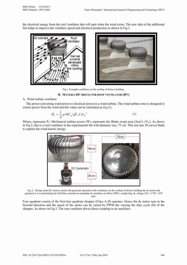
Where, represents PT: Mechanical turbine power (W), represents the Blade swept area (A(m2), (Vw). As shows in Fig.2, this is a roof ventilator in the experimental lab with diameter size, 75 cm. This size has 30 curves blade to capture the wind kinetic energy.
Fig. 2. Design main DC sources motor and generator operation with ventilators on the rooftop of factory building the dc motor and
generator it is a maintaining the field flux constant on nameplate dc machines as follow SPEC, weight 6kg, dc voltage 24V, 117W, 1470 rpm.
Four quadrant consist of the first-four quadrant chopper (Class A-D) operates. Hence the dc motor runs in the forward direction and the speed of the motor can be varied by PWM the varying the duty cycle (D) of the chopper. As shows in Fig.3. The root ventilator drives direct coupling to dc machines.
ISSN (Print) : 2319-8613 ISSN (Online) : 0975-4024 Narin Watanakul / International Journal of Engineering and Technology (IJET)
DOI: 10.21817/ijet/2020/v12i3/201203016 Vol 12 No 3 May-Jun 2020 464
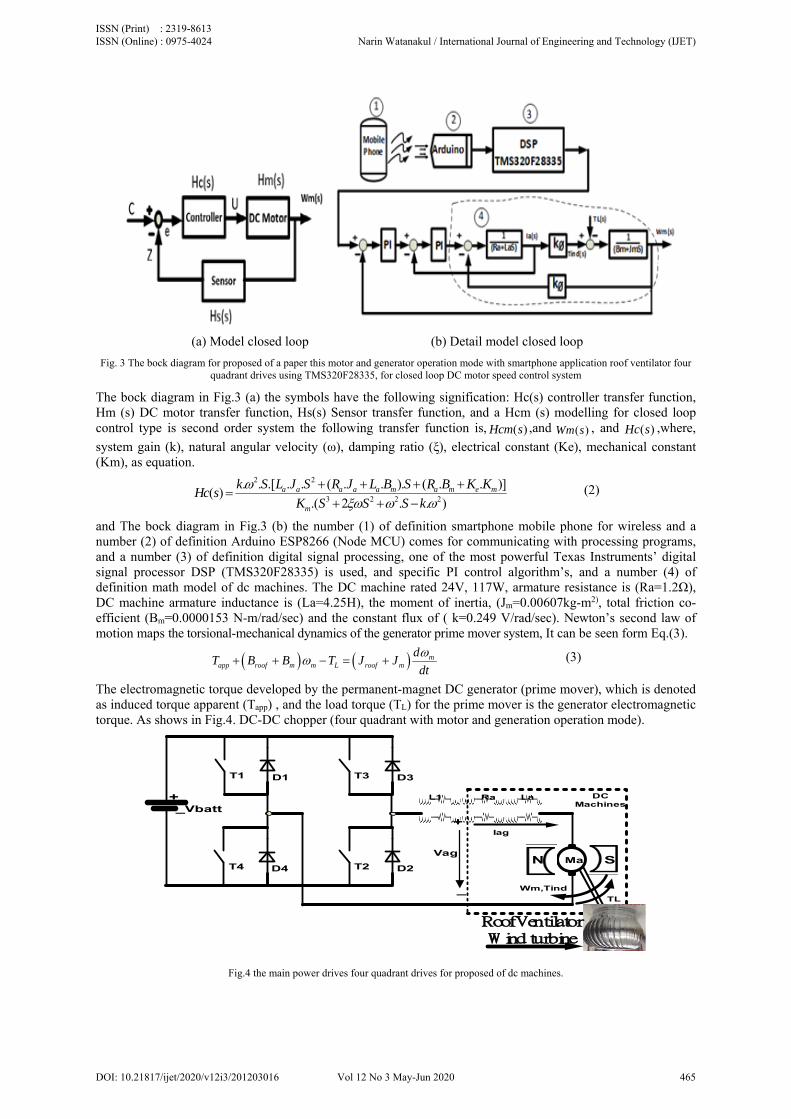
(a) Model closed loop (b) Detail model closed loop
Fig. 3 The bock diagram for proposed of a paper this motor and generator operation mode with smartphone application roof ventilator four quadrant drives using TMS320F28335, for closed loop DC motor speed control system
The bock diagram in Fig.3 (a) the symbols have the following signification: Hc(s) controller transfer function, Hm (s) DC motor transfer function, Hs(s) Sensor transfer function, and a Hcm (s) modelling for closed loop control type is second order system the following transfer function is, ( )Hcm s ,and ( )Wm s , and ( )Hc s ,where,
system gain (k), natural angular velocity (ω), damping ratio (ξ), electrical constant (Ke), mechanical constant (Km), as equation.
2 2
3 2 2 2
. . .[ . . ( . . ). ( . . )]( )
.( 2 . . )a a a a a m a m e m
m
k S L J S R J L B S R B K KHc s
K S S S k
(2)
and The bock diagram in Fig.3 (b) the number (1) of definition smartphone mobile phone for wireless and a number (2) of definition Arduino ESP8266 (Node MCU) comes for communicating with processing programs, and a number (3) of definition digital signal processing, one of the most powerful Texas Instruments’ digital signal processor DSP (TMS320F28335) is used, and specific PI control algorithm’s, and a number (4) of definition math model of dc machines. The DC machine rated 24V, 117W, armature resistance is (Ra=1.2Ω), DC machine armature inductance is (La=4.25H), the moment of inertia, (Jm=0.00607kg-m2), total friction co-efficient (Bm=0.0000153 N-m/rad/sec) and the constant flux of ( k=0.249 V/rad/sec). Newton’s second law of motion maps the torsional-mechanical dynamics of the generator prime mover system, It can be seen form Eq.(3).
mapp roof m m L roof m
dT B B T J J
dt
(3)
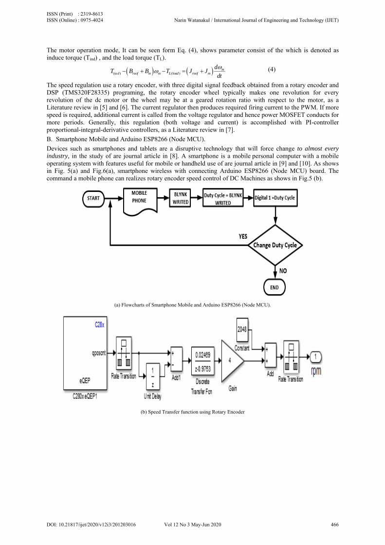
The electromagnetic torque developed by the permanent-magnet DC generator (prime mover), which is denoted as induced torque apparent (Tapp) , and the load torque (TL) for the prime mover is the generator electromagnetic torque. As shows in Fig.4. DC-DC chopper (four quadrant with motor and generation operation mode).
N SMa
Ra La
Wm,Tind
D2T2
L1 DC Machines
Vag
TL
Iag+
_
Roof Ventilator W ind turbine
D3T3D1T1
D4T4
+_Vbatt
Fig.4 the main power drives four quadrant drives for proposed of dc machines.
ISSN (Print) : 2319-8613 ISSN (Online) : 0975-4024 Narin Watanakul / International Journal of Engineering and Technology (IJET)
DOI: 10.21817/ijet/2020/v12i3/201203016 Vol 12 No 3 May-Jun 2020 465
The motor operation mode, It can be seen form Eq. (4), shows parameter consist of the which is denoted as induce torque (Tind) , and the load torque (TL).
(in ) ( )m
d roof m m L load roof m
dT B B T J J
dt
(4)
The speed regulation use a rotary encoder, with three digital signal feedback obtained from a rotary encoder and DSP (TMS320F28335) programing, the rotary encoder wheel typically makes one revolution for every revolution of the dc motor or the wheel may be at a geared rotation ratio with respect to the motor, as a Literature review in [5] and [6]. The current regulator then produces required firing current to the PWM. If more speed is required, additional current is called from the voltage regulator and hence power MOSFET conducts for more periods. Generally, this regulation (both voltage and current) is accomplished with PI-controller proportional-integral-derivative controllers, as a Literature review in [7].
B. Smartphone Mobile and Arduino ESP8266 (Node MCU).
Devices such as smartphones and tablets are a disruptive technology that will force change to almost every industry, in the study of are journal article in [8]. A smartphone is a mobile personal computer with a mobile operating system with features useful for mobile or handheld use of are journal article in [9] and [10]. As shows in Fig. 5(a) and Fig.6(a), smartphone wireless with connecting Arduino ESP8266 (Node MCU) board. The command a mobile phone can realizes rotary encoder speed control of DC Machines as shows in Fig.5 (b).
(a) Flowcharts of Smartphone Mobile and Arduino ESP8266 (Node MCU).
(b) Speed Transfer function using Rotary Encoder
ISSN (Print) : 2319-8613 ISSN (Online) : 0975-4024 Narin Watanakul / International Journal of Engineering and Technology (IJET)
DOI: 10.21817/ijet/2020/v12i3/201203016 Vol 12 No 3 May-Jun 2020 466
(c) Current Transfer function using Hall Effect with MATLAB Simulink.
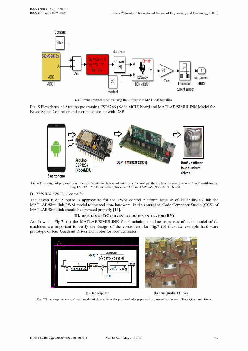
Fig. 5 Flowcharts of Arduino programing ESP8266 (Node MCU) board and MATLAB/SIMULINK Model for Based Speed Controller and current controller with DSP
Fig. 6 The design of proposed controller roof ventilator four quadrant drives Technology, the application wireless control roof ventilator by
using TMS320F28335 with smartphone and Arduino ESP8266 (Node MCU) board
D. TMS 320 F28335 Controller
The eZdsp F28335 board is appropriate for the PWM control platform because of its ability to link the MATLAB/Simulink PWM model to the real-time hardware. In the controller, Code Composer Studio (CCS) of MATLAB/Simulink should be operated properly [11].
III. RESULTS OF DC DRIVES FOR ROOF VENTILATOR (RV)
As shown in Fig.7. (a) the MATLAB/SIMULINK for simulation on time responses of math model of dc machines are important to verify the design of the controllers, for Fig.7 (b) illustrate example hard ware prototype of four Quadrant Drives DC motor for roof ventilator.
(a) Step response (b) Four Quadrant Drives
Fig. 7 Time step response of math model of dc machines for proposed of a paper and prototype hard ware of Four Quadrant Drives
ISSN (Print) : 2319-8613 ISSN (Online) : 0975-4024 Narin Watanakul / International Journal of Engineering and Technology (IJET)
DOI: 10.21817/ijet/2020/v12i3/201203016 Vol 12 No 3 May-Jun 2020 467
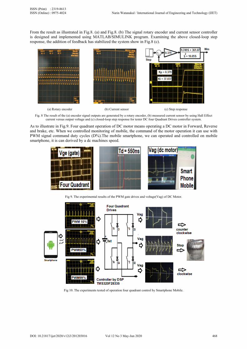
From the result as illustrated in Fig.8. (a) and Fig.8. (b) The signal rotary encoder and current sensor controller is designed and implemented using MATLAB/SIMULINK program. Examining the above closed-loop step response, the addition of feedback has stabilized the system show in Fig.8 (c).
(a) Rotary encoder (b) Current sensor (c) Step response
Fig. 8 The result of the (a) encoder signal outputs are generated by a rotary encoder, (b) measured current sensor by using Hall Effect current versus output voltage and (c) closed-loop step response for tester DC four Quadrant Drives controller system.
As to illustrate in Fig.9. Four quadrant operation of DC motor means operating a DC motor in Forward, Reverse and brake, etc. When we controlled monitoring of mobile, the command of the motor operation it can use with PWM signal command duty cycles (D%).The mobile smartphone, we can operated and controlled on mobile smartphone, it is can derived by a dc machines speed.
Fig 9. The experimental results of the PWM gate drives and voltage(Vag) of DC Motor.
Fig 10. The experiments tested of operation four quadrant control by Smartphone Mobile.
ISSN (Print) : 2319-8613 ISSN (Online) : 0975-4024 Narin Watanakul / International Journal of Engineering and Technology (IJET)
DOI: 10.21817/ijet/2020/v12i3/201203016 Vol 12 No 3 May-Jun 2020 468
IV. CONCLUSIONS OF DC DRIVES FOR ROOF VENTILATOR (RV)
A paper proposed variable speed dc motor control with a buck converter, and the load will use the energy from the batteries dc power supply. This work describes the modified roof ventilator that can control four-quadrant drives dc machines. The system uses a new smartphone application designed by App Inventor. This application can control variable speed dc motor of roof ventilator from the smartphone and Arduino ESP8266 (Node MCU) board. The speed of a dc motor has been successfully controlled by using chopper as a full converter and proportional-integral (PI) type speed and current controller based on closed-loop system model. The model shows good results under all conditions employed during the simulation. The prototype system is built and tested in the laboratory. The control system can make it the energy though out, In the case of the small power for roof ventilation wind turbine and speed control, for case study example, the electrical energy power storage into battery technology, Also this study also provides a guideline to further analyses and improve power.
V. INTRODUCTION AC DRIVES FOR SPIM
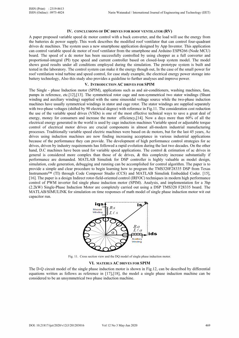
The Single - phase Induction motor (SPIM), applications such as and air-conditioners, washing machines, fans, pumps in reference, etc.[12],[13]. The symmetrical rotor cage and non-symmetrical two stator windings (Shunt winding and auxiliary winding) supplied with the same sinusoidal voltage source while the two-phase induction machines have usually symmetrical windings in stator and cage rotor. The stator windings are supplied separately with two-phase voltages (shifted by 90 electrical degree) with reference in Fig.11. The consideration cost reduction the use of the variable speed drives (VSDs) is one of the most effective technical ways to save a great deal of energy, money for consumers and increase the motor efficiency,[14]. Now a days more than 60% of all the electrical energy generated in the world is used by cage induction machines Variable speed or adjustable torque control of electrical motor drives are crucial components in almost all-modern industrial manufacturing processes. Traditionally variable speed electric machines were based on dc motors, but for the last 45 years, Ac drives using induction machines are now finding increasing acceptance in various industrial applications because of the performance they can provide. The development of high performance control strategies for ac drives, driven by industry requirements has followed a rapid evolution during the last two decades. On the other hand, D.C machines have been used for variable speed applications. The control & estimation of ac drives in general is considered more complex than those of dc drives, & this complexity increase substantially if performance are demanded. MATLAB Simulink for DSP controller is highly valuable as model design, simulation, code generation, debugging and running can be accomplished for control algorithm. The paper is to provide a simple and clear procedure to begin learning how to program the TMS320F28335 DSP from Texas Instruments™ (TI) through Code Composer Studio (CCS) and MATLAB Simulink Embedded Coder. [15], [16]. The paper is a design Indirect rotor-field-oriented control (IRFOC) techniques in modern high performance control of PWM inverter fed single phase induction motor (SPIM). Analysis, and implementation for a 3hp (2.2kW) Single-Phase Induction Motor are completely carried out using a DSP TMS320 F28335 board. The MATLAB/SIMULINK for simulation on time responses of math model of single phase induction motor wit out capacitor run.
Fig. 11. Cross section view and the DQ model of single phase induction motor.
VI. MATERLS AC DRIVES FOR SPIM
The D-Q circuit model of the single phase induction motor is shown in Fig.12, can be described by differential equations written as follows as reference in [17],[18], the model a single phase induction machine can be considered to be an unsymmetrical two phase induction machine.
ISSN (Print) : 2319-8613 ISSN (Online) : 0975-4024 Narin Watanakul / International Journal of Engineering and Technology (IJET)
DOI: 10.21817/ijet/2020/v12i3/201203016 Vol 12 No 3 May-Jun 2020 469
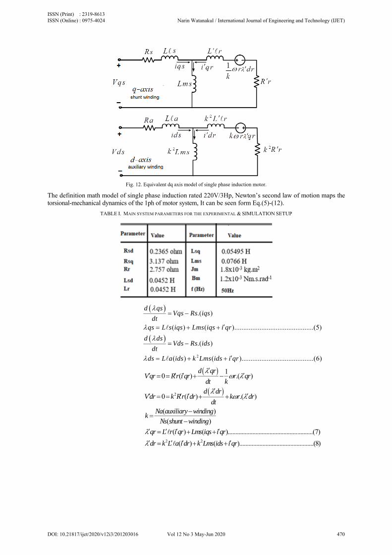
Fig. 12. Equivalent dq axis model of single phase induction motor.
The definition math model of single phase induction rated 220V/3Hp, Newton’s second law of motion maps the torsional-mechanical dynamics of the 1ph of motor system, It can be seen form Eq.(5)-(12).
TABLE I. MAIN SYSTEM PARAMETERS FOR THE EXPERIMENTAL & SIMULATION SETUP
2
.( )
( ) ( )............................................(5)
.( )
( ) ( )........................................(6)
d qsVqs Rs iqs
dtqs L s iqs Lms iqs i qr
d dsVds Rs ids
dt
ds L a ids k Lms ids i qr
2
10 ( ) .( )
0 ( ) .( )
( )
( )
( ) ( ).......................................................(7)
d qrVqr Rr i qr r qr
dt kd dr
Vdr k Rr i dr k r drdt
Na auxiliary windingk
Ns shunt winding
qr L r i qr Lms iqs i qr
2 2( ) ( )................................................(8)dr k L a i dr k Lms ids i qr
ISSN (Print) : 2319-8613 ISSN (Online) : 0975-4024 Narin Watanakul / International Journal of Engineering and Technology (IJET)
DOI: 10.21817/ijet/2020/v12i3/201203016 Vol 12 No 3 May-Jun 2020 470
2
1.
1
1; ( 1)
1 1
0
1 ..................................................
e
e
e
e
T P k qr i dr dr i qrk
LmsT P dr iqs k qr ids
L r k
ids ids iqs k iqs
LmsT P k dr iqs qr ids
L rqr
LmsT P k dr iqs
L r
.......(9)
2
,
;
.1 .......................................................................(10)
. . .
1 ................................................
e L d d mm
e
d r PT T T T B r
dt J
dr r L r L r
T L riqs
k Lms P r
rids
k Lms
3
...............................(11)
. ( 1).......................................................................(12)
( )s
k Lms iqsL r
rR r
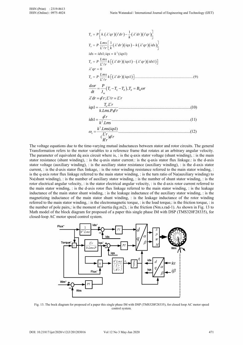
The voltage equations due to the time-varying mutual inductances between stator and rotor circuits. The general Transformation refers to the motor variables to a reference frame that rotates at an arbitrary angular velocity. The parameter of equivalent dq axis circuit where is, : is the q-axis stator voltage (shunt winding), : is the main stator resistance (shunt winding), : is the q-axis stator current.: is the q-axis stator flux linkage.: is the d-axis stator voltage (auxiliary winding), : is the auxiliary stator resistance (auxiliary winding), : is the d-axis stator current, : is the d-axis stator flux linkage, : is the rotor winding resistance referred to the main stator winding, : is the q-axis rotor flux linkage referred to the main stator winding, : is the turn ratio of Na(auxiliary winding) to Ns(shunt winding), : is the number of auxiliary stator winding, : is the number of shunt stator winding, : is the rotor electrical angular velocity, : is the stator electrical angular velocity, : is the d-axis rotor current referred to the main stator winding, : is the d-axis rotor flux linkage referred to the main stator winding, : is the leakage inductance of the main stator shunt winding, : is the leakage inductance of the auxiliary stator winding, : is the magnetizing inductance of the main stator shunt winding, : is the leakage inductance of the rotor winding referred to the main stator winding, : is the electromagnetic torque, : is the load torque,: is the friction torque, : is the number of pole pairs,: is the moment of inertia (kg.m2), : is the friction (Nm.s.rad-1). As shown in Fig. 13 to Math model of the block diagram for proposed of a paper this single phase IM with DSP (TMS320F28335), for closed-loop AC motor speed control system.
Fig. 13. The bock diagram for proposed of a paper this single phase IM with DSP (TMS320F28335), for closed loop AC motor speed
control system.
ISSN (Print) : 2319-8613 ISSN (Online) : 0975-4024 Narin Watanakul / International Journal of Engineering and Technology (IJET)
DOI: 10.21817/ijet/2020/v12i3/201203016 Vol 12 No 3 May-Jun 2020 471
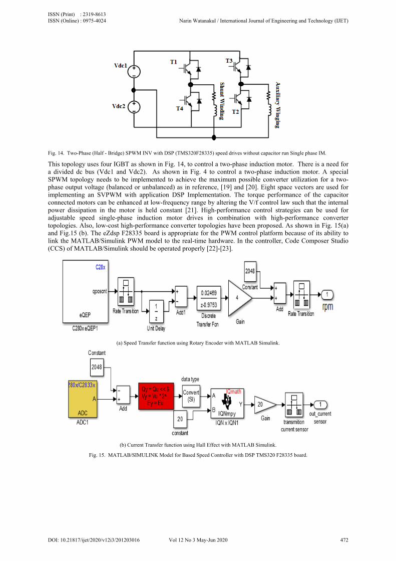
Fig. 14. Two-Phase (Half - Bridge) SPWM INV with DSP (TMS320F28335) speed drives without capacitor run Single phase IM.
This topology uses four IGBT as shown in Fig. 14, to control a two-phase induction motor. There is a need for a divided dc bus (Vdc1 and Vdc2). As shown in Fig. 4 to control a two-phase induction motor. A special SPWM topology needs to be implemented to achieve the maximum possible converter utilization for a two-phase output voltage (balanced or unbalanced) as in reference, [19] and [20]. Eight space vectors are used for implementing an SVPWM with application DSP Implementation. The torque performance of the capacitor connected motors can be enhanced at low-frequency range by altering the V/f control law such that the internal power dissipation in the motor is held constant [21]. High-performance control strategies can be used for adjustable speed single-phase induction motor drives in combination with high-performance converter topologies. Also, low-cost high-performance converter topologies have been proposed. As shown in Fig. 15(a) and Fig.15 (b). The eZdsp F28335 board is appropriate for the PWM control platform because of its ability to link the MATLAB/Simulink PWM model to the real-time hardware. In the controller, Code Composer Studio (CCS) of MATLAB/Simulink should be operated properly [22]-[23].
(a) Speed Transfer function using Rotary Encoder with MATLAB Simulink.
(b) Current Transfer function using Hall Effect with MATLAB Simulink.
Fig. 15. MATLAB/SIMULINK Model for Based Speed Controller with DSP TMS320 F28335 board.
ISSN (Print) : 2319-8613 ISSN (Online) : 0975-4024 Narin Watanakul / International Journal of Engineering and Technology (IJET)
DOI: 10.21817/ijet/2020/v12i3/201203016 Vol 12 No 3 May-Jun 2020 472
VII. RESULTS FOR AC DRIVES FOR SPIM
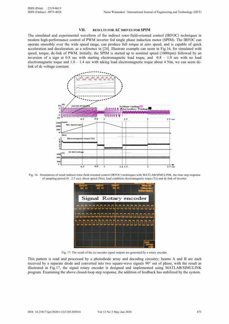
The simulated and experimental waveform of the indirect rotor-field-oriented control (IRFOC) techniques in modern high-performance control of PWM inverter fed single phase induction motor (SPIM). The IRFOC can operate smoothly over the wide speed range, can produce full torque at zero speed, and is capable of quick acceleration and deceleration, as a reference in [24]. Illustrate example can seem in Fig.16, for simulated with speed, torque, dc-link of PWM. Initially, the SPIM is started up to nominal speed (1000rpm) followed by an inversion of a sign at 0.8 sec with starting electromagnetic load toque, and 0.8 – 1.0 sec with no load electromagnetic toque and 1.0 – 1.4 sec with taking load electromagnetic toque about 4 Nm, we can seem dc-link of dc voltage constant.
Fig. 16. Simulations of result indirect rotor-field-oriented control (IRFOC) techniques with MATLAB/SIMULINK, the time step response
of sampling period (0 - 2.5 sec), about speed (Nm), load condition electromagnetic toque (Te) and dc-link of inverter.
Fig. 17. The result of the (a) encoder signal outputs are generated by a rotary encoder.
This pattern is read and processed by a photodiode array and decoding circuitry; beams A and B are each received by a separate diode and converted into two square-wave signals 90° out of phase, with the result as illustrated in Fig.17, the signal rotary encoder is designed and implemented using MATLAB/SIMULINK program. Examining the above closed-loop step response, the addition of feedback has stabilized by the system.
ISSN (Print) : 2319-8613 ISSN (Online) : 0975-4024 Narin Watanakul / International Journal of Engineering and Technology (IJET)
DOI: 10.21817/ijet/2020/v12i3/201203016 Vol 12 No 3 May-Jun 2020 473
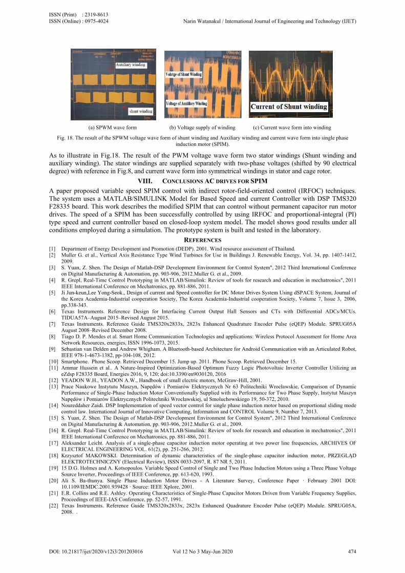
(a) SPWM wave form (b) Voltage supply of winding (c) Current wave form into winding
Fig. 18. The result of the SPWM voltage wave form of shunt winding and Auxiliary winding and current wave form into single phase induction motor (SPIM).
As to illustrate in Fig.18. The result of the PWM voltage wave form two stator windings (Shunt winding and auxiliary winding). The stator windings are supplied separately with two-phase voltages (shifted by 90 electrical degree) with reference in Fig.8, and current wave form into symmetrical windings in stator and cage rotor.
VIII. CONCLUSIONS AC DRIVES FOR SPIM
A paper proposed variable speed SPIM control with indirect rotor-field-oriented control (IRFOC) techniques. The system uses a MATLAB/SIMULINK Model for Based Speed and current Controller with DSP TMS320 F28335 board. This work describes the modified SPIM that can control without permanent capacitor run motor drives. The speed of a SPIM has been successfully controlled by using IRFOC and proportional-integral (PI) type speed and current controller based on closed-loop system model. The model shows good results under all conditions employed during a simulation. The prototype system is built and tested in the laboratory.
REFERENCES [1] Department of Energy Development and Promotion (DEDP). 2001. Wind resource assessment of Thailand. [2] Muller G. et al., Vertical Axis Resistance Type Wind Turbines for Use in Buildings J. Renewable Energy, Vol. 34, pp. 1407-1412,
2009. [3] S. Yuan, Z. Shen. The Design of Matlab-DSP Development Environment for Control System", 2012 Third International Conference
on Digital Manufacturing & Automation, pp. 903-906, 2012.Muller G. et al., 2009. [4] R. Grepl, Real-Time Control Prototyping in MATLAB/Simulink: Review of tools for research and education in mechatronics", 2011
IEEE International Conference on Mechatronics, pp. 881-886, 2011. [5] Ji Jun-keun,Lee Yong-Seok., Design of current and Speed controller for DC Motor Drives System Using dSPACE System, Journal of
the Korea Academia-Industrial cooperation Society, The Korea Academia-Industrial cooperation Society, Volume 7, Issue 3, 2006, pp.338-343.
[6] Texas Instruments. Reference Design for Interfacing Current Output Hall Sensors and CTs with Differential ADCs/MCUs. TIDUA57A–August 2015–Revised August 2015.
[7] Texas Instruments. Reference Guide TMS320x2833x, 2823x Enhanced Quadrature Encoder Pulse (eQEP) Module. SPRUG05A August 2008–Revised December 2008.
[8] Tiago D. P. Mendes et al. Smart Home Communication Technologies and applications: Wireless Protocol Assessment for Home Area Network Resources, energies, ISSN 1996-1073, 2015.
[9] Sebastian van Delden and Andrew Whigham. A Bluetooth-based Architecture for Android Communication with an Articulated Robot, IEEE 978-1-4673-1382, pp-104-108, 2012.
[10] Smartphone. Phone Scoop. Retrieved December 15. Jump up. 2011. Phone Scoop. Retrieved December 15. [11] Ammar Hussein et al.. A Nature-Inspired Optimization-Based Optimum Fuzzy Logic Photovoltaic Inverter Controller Utilizing an
eZdsp F28335 Board, Energies 2016, 9, 120; doi:10.3390/en9030120, 2016 [12] YEADON W.H., YEADON A.W., Handbook of small electric motors, McGraw-Hill, 2001. [13] Prace Naukowe Instytutu Maszyn, Napędów i Pomiarów Elektrycznych Nr 63 Politechniki Wrocławskie, Comparison of Dynamic
Performance of Single-Phase Induction Motor Conventionally Supplied with its Performance for Two Phase Supply, Instytut Maszyn Napędów i Pomiarów Elektrycznych Politechniki Wrocławskiej, ul Smoluchowskiego 19, 50-372, 2010.
[14] Noureddaher Zaidi. DSP Implementation of speed vector control for single phase induction motor based on proportional sliding mode control law. International Journal of Innovative Computing, Information and CONTROL Volume 9, Number 7, 2013.
[15] S. Yuan, Z. Shen. The Design of Matlab-DSP Development Environment for Control System", 2012 Third International Conference on Digital Manufacturing & Automation, pp. 903-906, 2012.Muller G. et al., 2009.
[16] R. Grepl. Real-Time Control Prototyping in MATLAB/Simulink: Review of tools for research and education in mechatronics", 2011 IEEE International Conference on Mechatronics, pp. 881-886, 2011.
[17] Aleksander Leicht. Analysis of a single-phase capacitor induction motor operating at two power line frequencies, ARCHIVES OF ELECTRICAL ENGINEERING VOL. 61(2), pp. 251-266, 2012.
[18] Krzysztof MAKOWSKI. Determination of dynamic characteristics of the single-phase capacitor induction motor, PRZEGLĄD ELEKTROTECHNICZNY (Electrical Review), ISSN 0033-2097, R. 87 NR 5, 2011.
[19] 15 D.G. Holmes and A. Kotsopoulos. Variable Speed Control of Single and Two Phase Induction Motors using a Three Phase Voltage Source Inverter, Proceedings of IEEE Conference, pp. 613-620, 1993.
[20] Ali S. Ba-thunya. Single Phase Induction Motor Drives - A Literature Survey, Conference Paper ꞏ February 2001 DOI: 10.1109/IEMDC.2001.939428 ꞏ Source: IEEE Xplore, 2001.
[21] E.R. Collins and R.E. Ashley. Operating Characteristics of Single-Phase Capacitor Motors Driven from Variable Frequency Supplies, Proceedings of IEEE-IAS Conference, pp. 52-57, 1991.
[22] Texas Instruments. Reference Guide TMS320x2833x, 2823x Enhanced Quadrature Encoder Pulse (eQEP) Module. SPRUG05A, 2008. .
ISSN (Print) : 2319-8613 ISSN (Online) : 0975-4024 Narin Watanakul / International Journal of Engineering and Technology (IJET)
DOI: 10.21817/ijet/2020/v12i3/201203016 Vol 12 No 3 May-Jun 2020 474

[23] Tiago D. P. Mendes et al. Smart Home Communication Technologies and applications: Wireless Protocol Assessment for Home Area Network Resources, energies, ISSN 1996-1073, 2015.
[24] Venu Gopal B. Comparison between Direct and Indirect Field Oriented Control of Induction Motor, International Journal of Engineering Trends and Technology (IJETT) Volume-43 Number-6 –January, 2017.
AUTHOR PROFILE
Narin Watanakul graduated from the King Mongkut's University of Technology North Bangkok, in Electrical Engineering (1986). He received Master of Engineering degree (1993) from the same university. Currently, he is Associate Professor of the department of electrical & computer engineering, Thammasat University. He is currently PhD Candidate at Faculty of Engineering Mahasarakham University (MSU), Thailand since 2008 respectively. His main research interests include power electronics Renewable energy converters, power quality.
ISSN (Print) : 2319-8613 ISSN (Online) : 0975-4024 Narin Watanakul / International Journal of Engineering and Technology (IJET)
DOI: 10.21817/ijet/2020/v12i3/201203016 Vol 12 No 3 May-Jun 2020 475