Embed Size (px)
Citation preview

1
PATENT PROTECTION NOTICE
The method for structure deformed shape predictions using Ko Displacement Theory for transforming surface strains into structural deformed shapes
described in this Conference Paper is protected under Method for Real-Time Structure Shape-Sensing, U.S. Patent No. 7,520,176 issued April 21, 2009.
Therefore, those interested in using the Method should contact NASA Innovative Partnership Program Office, NASA Armstrong Flight Research Center,
Edwards, California for more information.
GOVERNMENT RIGHTS NOTICE
This work was authored by employees of Shun-Fat Lung under Contract No. NND08RR01B with the National Aeronautics and Space Administration.
The United States Government retains and the publisher, by accepting the article for publication, acknowledges that the United States Government retains a non-exclusive, paid-up, irrevocable, worldwide license to reproduce, prepare derivative works, distribute copies to the public, and perform publicly and
display publicly, or allow others to do so, for United States Government purposes. All other rights are reserved by the copyright owner.
Abstract
In support of the Adaptive Compliant Trailing
Edge [ACTE] project at the NASA Armstrong
Flight Research Center, displacement transfer
functions were applied to the swept wing of a
Gulfstream G-III airplane (Gulfstream
Aerospace Corporation, Savannah, Georgia) to
obtain deformed shape predictions. Four strain-
sensing lines (two on the lower surface, two on
the upper surface) were used to calculate the
deformed shape of the G III wing under bending
and torsion. There being an insufficient number
of surface strain sensors, the existing G III wing
box finite element model was used to generate
simulated surface strains for input to the
displacement transfer functions. The resulting
predicted deflections have good correlation with
the finite-element generated deflections as well
as the measured deflections from the ground load
calibration test. The convergence study showed
that the displacement prediction error at the G
III wing tip can be reduced by increasing the
number of strain stations (for each strain-sensing
line) down to a minimum error of l.6 percent at
17 strain stations; using more than 17 strain
stations yielded no benefit because the error
slightly increased to 1.9% when 32 strain
stations were used.
Nomenclature
ACTE Adaptive Compliant Trailing Edge AFRC Armstrong Flight Research Center
DTF displacement transfer functions
FEM finite element model
G-III Gulfstream III airplane
LRT linear resistance transducer
NASA National Aeronautics and Space Administration
P bending load
T torsion load
𝑐𝑖 lower depth factor (vertical distance from neutral
axis to lower surface strain station i, inches
𝑐�̅� upper depth factor (vertical distance from neutral
axis to upper surface strain station i, inches
𝑑𝑖 strain-sensing line separation distance at
strain-sensing station i
𝑑0 value of 𝑑𝑖 at the wing root, 𝑥 = 𝑥0 = 0
𝑑𝑛 value of 𝑑𝑖 at the wing tip, 𝑥 = 𝑥𝑛 = 𝑙 hi (beam) depth of structure at strain station i
i = 0,1,2, …,n, strain station identification number
l length of strain-sensing line, inches
n index for the last span-wise strain station
(or number of strain-sensing domains)
𝑤𝑛 wing tip chord length (width), inches
𝑤0 wing root chord length (width), inches
x, y Cartesian coordinates (x in span-wise direction,
y in lateral direction), inches
𝑥𝑖 axial coordinate associated with
i-th strain
station, inches
𝑦𝑖 deflection at axial location 𝑥 = 𝑥𝑖 , inches
𝜀𝑖 lower surface strain at 𝑥 = 𝑥𝑖
APPLICATIONS OF DISPLACEMENT TRANSFER FUNCTIONS TO DEFORMED SHAPE PREDICTIONS
OF THE G-III SWEPT-WING STRUCTURE
Shun-Fat Lung1 and William L. Ko2 1Jacobs Technology Inc., Edwards, California, 93523-0273
2NASA Armstrong Flight Research Center, Edwards, California, 93523-0723
Keywords: shape, sensing, strain, displacement, DTFs

LUNG, KO
2
𝜀�̅� upper surface strain at 𝑥 = 𝑥𝑖
(∆𝑙)𝑖 ≡ (𝑥𝑖 − 𝑥𝑖−1), domain length (distance between
two adjacent strain stations at 𝑥 = 𝑥𝑖−1 and
𝑥 = 𝑥𝑖, inches
𝜃𝑖 slope of neutral axis at 𝑥 = 𝑥𝑖, rad or deg
( )′ quantity associated with rear strain-sensing lines
𝜙𝑖 twist angle at 𝑥 = 𝑥𝑖, rad or deg
1 Introduction
In late 2009, the NASA Armstrong Flight
Research Center [AFRC] acquired a Gulfstream
III [G-III] business jet airplane (Gulfstream
Aerospace Corporation, Savannah, Georgia) to
conduct various research projects. The G-III
airplane, tail number 804, shown in Fig. 1, was
modified and instrumented by NASA AFRC
personnel to serve as a SubsoniC Research
Aircraft Testbed [SCRAT] [1] for a variety of
flight research experiments in support of the
Environmentally Responsible Aviation [ERA]
projects. The twin-turbofan engines provide
long-term capability for efficient testing of
subsonic flight experiments for NASA, the
United States Air Force, other government
agencies, academia, and private industry.
The current AFRC project utilizing the
G-III airplane is the Adaptive Compliant Trailing
Edge [ACTE] flap experiment. These
unconventional adaptive compliant flap
structures developed by FlexSys Inc. (Ann
Arbor, Michigan) replaced the conventional
Fowler flaps. Due to differences between the
ACTE structure and the original Fowler flaps
with respect to weight, geometry, and
flight-testing conditions, the aerodynamic and
inertial loads were expected to be different.
In order to protect the wing structure during
flight, load equations were developed using
strains loads data from a ground load calibration
test. [2] These load equations were integrated in
the Mission Control Room for real-time
monitoring of the aerodynamic loads during
flight. Wing deflected shape under load was also
characterized and used to tune existing finite
element models [FEMs] of the G-III wing
structure.
Real-time deformed shape estimation of
aerospace structures in flight is important for
aircraft performance, safety of flight, and fuel
efficiency. In order to enable the real-time shape
sensing, Ko, et al. [3, 4, 5] developed the
displacement transfer functions [DTFs] using a
discretization approach to piecewise integrate the
beam curvature-strain differential equations for
transforming the in-flight measured surface
strains into overall wing deformed shapes.
The DTFs combined with the on-board
strain-sensing system (conventional strain gages
or fiber optic sensors) thus form a powerful
structure-shape-sensing technology invented by
Ko and Richards [6] for in-flight deformed shape
monitoring of flexible wings and tails. In
addition, the real-time wing shape can be input to
the aircraft control system for aeroelastic wing
shape control. The accuracies of the DTFs were
validated in the past using unswept aircraft
wings, such as those found on the Ikhana
Predator B (General Atomics, San Diego,
California, USA) [7] and the Global Observer
high-altitude, long-endurance remotely operated
aircraft (AeroVironment, Inc., Simi Valley,
California, USA). [8]
The objective of the present study is to
apply the DTFs to the shape predictions of the
G-III swept wing to demonstrate the accuracy
and efficiency of the DTFs for a real-time
deflection shape estimate tool. Unlike the
unswept wings of the Ikhana and the Global
Observer, the G-III swept wing is of more
complicated geometry and has uneven strain
distribution on the top and bottom surface skins.
There being an insufficient number of surface
strain sensors (strain gages are only installed on
two spanwise locations for flight-test monitoring
purposes), the existing G-III wing box FEM was
used to generate surface strains for input to the
DTFs. The resulting predicted deflections were
then compared with the FEM-generated
deflections as well as the measured deflections
from the ground load calibration test for
validating the accuracy of the DTFs when
applied to the swept-wing case.
2 Displacement Transfer Functions
The G-III ground load calibration test and
finite-element generated strains data can be used
to examine the shape-prediction accuracy of the
DTFs, and to reinforce the confidence in the

3
APPLICATIONS OF DISPLACEMENT TRANSFER FUNCTIONS TO DEFORMED SHAPE PREDICTIONS
OF THE G-III SWEPT-WING STRUCTURE
DTFs for future aircraft wing deformed shape
predictions.
The basic idea for the formulation of the
DTFs [2, 3] is to discretize the slender structure
cross section (embedded beam) along the
surface strain-sensing line (span-wisely oriented)
into n number of domains with domain junctures
matching the strain stations at 𝑥 = 𝑥𝑖 (𝑖 = 1,2,3, ⋯ , 𝑛) along the strain-sensing line.
Thus, the surface strain distribution can be
represented with piece-wise linear or piece-wise
nonlinear functions in terms of surface strains at
𝑥𝑖 . The discretization approach enables
integrations of the embedded beam curvature-
strain equation over each to yield slope and
deflection equations in recursive forms. Due to
the complexity of the structure geometry, various
slope and deflection equations were developed
based on non-uniform, slightly uniform, and
uniform geometry of the structure. A typical set
of slope and deflection equations written in
recursive forms for non-uniform structures are
shown, respectively, as Eq. (1) and Eq. (2):
Slope equation:
𝑡𝑎𝑛𝜃𝑖 = (∆𝑙)𝑖 [𝜀𝑖−1 − 𝜀𝑖
𝑐𝑖−1 − 𝑐𝑖
+𝜀𝑖−1𝑐𝑖 − 𝜀𝑖𝑐𝑖−1
(𝑐𝑖−1 − 𝑐𝑖)2𝑙𝑜𝑔
𝑐𝑖
𝑐𝑖−1
]
+ 𝑡𝑎𝑛𝜃𝑖−1
𝑆𝑙𝑖𝑔ℎ𝑡𝑙𝑦𝑛𝑜𝑛𝑢𝑛𝑖𝑓𝑜𝑟𝑚
(𝑐𝑖−1 ≈ 𝑐𝑖)→
(∆𝑙)𝑖
2𝑐𝑖−1
[(2 −𝑐𝑖
𝑐𝑖−1
) 𝜀𝑖−1 + 𝜀𝑖] + 𝑡𝑎𝑛𝜃𝑖−1
𝑈𝑛𝑖𝑓𝑜𝑟𝑚
(𝑐𝑖−1 = 𝑐𝑖 = 𝑐)→
(∆𝑙)𝑖
2𝑐(𝜀𝑖−1 + 𝜀𝑖) + 𝑡𝑎𝑛𝜃𝑖−1
(𝑖 = 1,2,3, ⋯ , 𝑛)
(1)
Deflection equation:
𝑦𝑖 = (∆𝑙)𝑖2 [
𝜀𝑖−1−𝜀𝑖
2(𝑐𝑖−1−𝑐𝑖)−
𝜀𝑖−1𝑐𝑖−𝜀𝑖𝑐𝑖−1
(𝑐𝑖−1−𝑐𝑖)3 (𝑐𝑖𝑙𝑜𝑔𝑐𝑖
𝑐𝑖−1+ (𝑐𝑖−1 − 𝑐𝑖))] +
𝑦𝑖−1 + (∆𝑙)𝑖𝑡𝑎𝑛𝜃𝑖−1
𝑆𝑙𝑖𝑔ℎ𝑡𝑙𝑦
𝑛𝑜𝑛𝑢𝑛𝑖𝑓𝑜𝑟𝑚
(𝑐𝑖−1≈𝑐𝑖)→
(∆𝑙)𝑖2
6𝑐𝑖−1[(3 −
𝑐𝑖
𝑐𝑖−1) 𝜀𝑖−1 + 𝜀𝑖] + 𝑦𝑖−1 +
(∆𝑙)𝑖𝑡𝑎𝑛𝜃𝑖−1 (2)
𝑈𝑛𝑖𝑓𝑜𝑟𝑚
(𝑐𝑖−1 = 𝑐𝑖 = 𝑐)→
(∆𝑙)𝑖2
6𝑐(2𝜀𝑖−1 + 𝜀𝑖) + 𝑦𝑖−1 + (∆𝑙)𝑖𝑡𝑎𝑛𝜃𝑖−1
(𝑖 = 1,2,3, ⋯ , 𝑛)
Equations {(1), (2)} are DTFs for transforming
surface strains into out-of-plane deflections
for mapping out overall structure deformed
shapes. The first set of equations
{(1), (2)} (for non-uniform structures) was used
in the deformed shape analysis of the wing of the
G-III airplane.
2.1 Characteristics of Displacement Transfer
Functions
In the DTFs, the deflections
𝑦𝑖 (𝑖 = 1,2,3, ⋯ , 𝑛)(𝑦0 = 0) at axial location
𝑥 = 𝑥𝑖 (𝑖 = 1,2,3, ⋯ , 𝑛) are expressed in terms
of the inboard depth factors (𝑐0, 𝑐1, 𝑐2, ⋯ , 𝑐𝑖) ,
and the associated inboard surface
strains (𝜀0, 𝜀1, 𝜀2, ⋯ , 𝜀𝑖), including the values of
{𝑐𝑖, 𝜀𝑖} at 𝑥 = 𝑥𝑖 where deflections 𝑦𝑖 , are
calculated.
It is important to mention that the DTFs
are purely geometrical relationships, containing
no material properties; however, it must be
understood that the outputs of the surface strains
can be affected by material properties and
internal structural configurations. When using
the DTFs for shape predictions of complex
structures such as aircraft wings, it is not
necessary to know the material properties, nor
the complex geometries of the internal structures.
2.2 Determination of Neutral Axis
For the calculations of deflection 𝑦𝑖 of the G-III
swept wing under bending load P and torsion
load T, four strain-sensing lines (two on the
lower surface and two on the upper surface), as
shown in Fig. 2, are required because the depth
factors are unknown. If the depth factors are
known, only two sensing lines on the lower
surface (or on the upper surface) are enough to
sense both bending and torsion.
The unknown front and rear depth factors
[{𝑐𝑖, 𝑐�̅�}, {𝑐𝑖′, 𝑐�̅�
′}] can be calculated by using the
associated pairs of lower and upper surface
strains [{𝜀𝑖, 𝜀�̅�}, {𝜀𝑖′, 𝜀�̅�
′}] at the same cross
section 𝑥 = 𝑥𝑖 as shown in Equations (3[a]) and
(3[b]):
e i
LUNG, KO
4
Front strain-sensing
cross section
Rear strain-sensing
cross section
Lower depth
factors:
𝑐𝑖 =𝜀𝑖
𝜀𝑖 + 𝜀�̅�
ℎ𝑖
𝑐𝑖′ =
𝜀𝑖′
𝜀𝑖′ + 𝜀�̅�
′ ℎ𝑖′
(3[a])
Upper depth
factors:
𝑐�̅� =𝜀�̅�
𝜀𝑖 + 𝜀�̅�
ℎ𝑖
𝑐�̅�′ =
𝜀�̅�′
𝜀𝑖′ + 𝜀�̅�
′ ℎ𝑖′
(3[b])
in which {ℎ𝑖(= 𝑐𝑖 + 𝑐�̅�), ℎ𝑖′(= 𝑐𝑖
′ + 𝑐�̅�′)} are,
respectively, the depths at 𝑥 = 𝑥𝑖 of structure
cross sections along the front and rear
strain-sensing lines (Fig. 2). For a
linearly-tapered wing structure, {ℎ𝑖, ℎ𝑖′} can be
written as shown in Equation (3[c]):
ℎ𝑖 = ℎ0 −𝑥𝑖
𝑙(ℎ0 − ℎ𝑛) ℎ𝑖
′ = ℎ0′ −
𝑥𝑖
𝑙(ℎ0
′ − ℎ𝑛′ ) (3[c])
in which [{ℎ0, ℎ0′ }, {ℎ𝑛, ℎ𝑛
′ }] are, respectively,
the values of {ℎ𝑖 , ℎ𝑖′} at the wing root 𝑥 = 𝑥0 and
wing tip 𝑥 = 𝑥𝑖.
2.3 Cross Sectional Twist Angle
If {𝑦𝑖, 𝑦𝑖′} respectively represent the
deflections at axial location 𝑥 = 𝑥𝑖 (Fig. 2) of the
front and rear embedded beams separated by a
distance 𝑑𝑖, then the cross sectional twist angle
𝜙𝑖 at 𝑥 = 𝑥𝑖 can be calculated from Eq. (4):
𝜙𝑖 = 𝑠𝑖𝑛−1 (𝑦𝑖 − 𝑦𝑖
′
𝑑𝑖
) ; (𝑖 = 0,1,2,3, ⋯ , 𝑛) (4)
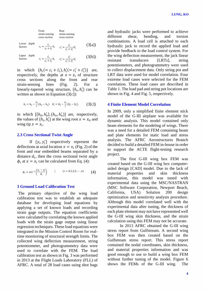
3 Ground Load Calibration Test
The primary objective of the wing load
calibration test was to establish an adequate
database for developing load equations by
applying a set of known loads and recording
strain gage outputs. The equation coefficients
were calculated by correlating the known applied
loads with the strain gage output using linear
regression techniques. These load equations were
integrated in the Mission Control Room for real-
time monitoring of structural strength limits. The
collected wing deflection measurement, string
potentiometer, and photogrammetry data were
used to correlate with the FEM. The load
calibration test as shown in Fig. 3 was performed
in 2013 at the Flight Loads Laboratory (FLL) of
AFRC. A total of 28 load cases using shot bags
and hydraulic jacks were performed to achieve
different shear, bending, and torsion
combinations. A load cell is attached to each
hydraulic jack to record the applied load and
provide feedback to the load control system. For
the wing deflection measurement, the jack linear
resistant transducers [LRTs], string
potentiometers, and photogrammetry were used
to collect displacement data. Only string pot and
LRT data were used for model correlation. Four
extreme load cases were selected for the FEM
correlation. These load cases are described in
Table 1. The load pad and string pot locations are
shown in Fig. 4 and Fig. 5, respectively.
4 Finite Element Model Correlation
In 2009, only a simplified finite element stick
model of the G-III airplane was available for
dynamic analysis. This model contained only
beam elements for the modeling of wings. There
was a need for a detailed FEM containing beam
and plate elements for static load and stress
analysis. The AFRC Aerostructures Branch
decided to build a detailed FEM in-house in order
to support the ACTE flight-testing research
project.
The first G-III wing box FEM was
created based on the G-III wing box computer-
aided design [CAD] model. Due to the lack of
material properties and skin thickness
information, this model was tuned with
experimental data using the MSC/NASTRAN
(MSC Software Corporation, Newport Beach,
California, USA) Solution 200 design
optimization and sensitivity analysis procedure.
Although this model correlated well with the
experimental data after tuning, the thickness of
each plate element may not have represented well
the G-III wing skin thickness, and the strain
calculation using this FEM may not be accurate.
In 2013 AFRC obtained the G-III wing
stress report from Gulfstream. A second wing
box FEM was then created based on the
Gulfstream stress report. This stress report
contained the nodal coordinates, skin thickness,
and material properties information and was
good enough to use to build a wing box FEM
without further tuning of the model. Figure 6
shows the FEMs of the G-III wing. The
5
APPLICATIONS OF DISPLACEMENT TRANSFER FUNCTIONS TO DEFORMED SHAPE PREDICTIONS
OF THE G-III SWEPT-WING STRUCTURE
correlation of the FEMs with the experimental
data are shown in Tables 2, 3, 4, and 5. All
deflections data shown in Tables 2 through 5
have been normalized for non-disclosure
purposes. The large percentage errors shown in
the tables are due to very small deflection at the
inboard section of the wing. For load case 1, only
string-pot-measured deflections were used to
correlate with the FEM. For load cases
3 and 6, only the aft or forward side of the
LRT-measured deflections were used for finite
element correlation, respectively. For load
case 24, all of the LRT-measured deflections
were used.
5 Displacement Transfer Functions
Application
After correlation of the G-III wing box FEM, the
strain output from the wing box FEM were
entered into one of the DTFs for the wing
deformed shape calculation. Since the second
wing box FEM was created based on the
information from the stress report, the thickness
of the skin surface is more accurate than the first
model. The second wing box FEM was thus used
for the strain and deflection calculations.
Due to the non-uniform geometry of the G-III
wing structure, four strain-sensing lines and
non-uniform displacement transfer functions
{Eqs. (1), (2)} were adapted to calculate the wing
deformed shape. The four strain-sensing lines
were located at the top and bottom surfaces of the
front and rear spars. Each strain-sensing line
contained 32 equally-spaced strain stations. The
depth factors were calculated from the
depth-factor equations {(3-a), (3-b)}.
Figures 7 and 8 depict finite-
element-generated strain outputs from the front
and rear strain-sensing lines for load case 24. The
deflections calculated from the DTFs [using the
bottom surface strains {𝜀𝑖, 𝜀𝑖′} and the lower
depth factors {𝑐𝑖, 𝑐𝑖′}], finite element method, and
experiment are shown in Figs. 9 and 10. The
deflections calculated from the DTFs compared
very well with the finite-element- and
LTRs-measured data.
Figure 11 shows the cross sectional twist
angles calculated from Eq. (4) [in view of
Equations (1) and (2)] and from finite element
analysis. The twist angle is calculated based on
the distance between the front and rear strain
stations, as indicated in Fig. 6. The correlation
between the finite element analysis and Eq. (4) is
quite good.
A convergence study was also performed
by using four different numbers (5, 9, 17, 32) of
strain stations to study how the accuracy of the
predicted deflections changes with the number of
strain stations used. Results of the convergent
study are shown in Fig. 12. It is shown that using
more strain stations to calculate the deflection
curve will match the finite-element deflection
curve very well.
Figure 13 shows that the predicted
wing-tip displacement error decreased with an
increasing number of strain stations, reaching a
minimum error of 1.6 percent at 17 strain
stations. Increasing the number of strain stations
beyond 17 yielded negligible benefit; the error
gradually increased to 1.9 percent at 32 strain
stations.
6 Concluding Remarks
The displacement transfer functions method for
structure deformed shape predictions was applied
to calculate the G-III swept-wing structure
deformed shapes of a Gulfstream G-III airplane
(Gulfstream Aerospace Corporation, Savannah,
Georgia, USA). The non-uniform displacement
transfer functions were used due to the
non-uniform geometry of the G-III wing
structure. Since the experimental surface strains
data were not available, the surface strains
generated by the correlated finite element model
were used to enter into the displacement transfer
functions for the deformed shape calculation.
The calculated deformed shapes are very close to
the correlated finite element results as well as to
the measured data. The convergence study
showed that using 17 strain stations, the wing-tip
displacement prediction error was 1.6 percent,
and that there is no need to use a large number of
strain stations for G-III wing shape predictions.
References

LUNG, KO
6
[1] Baumann E, Hernandez J and Ruhf J. An Overview of
NASA’s SubsoniC Research Aircraft Testbed
(SCRAT). AIAA-2013-5083, 2013.
[2] Lokos W, Miller E, Hudson L, Holguin A, Neufeld D
and Haraguchi R. Strain Gage Loads Calibration
Testing with Airbag Support for the Gulfstream III
SubsoniC Research Aircraft Testbed (SCRAT). AIAA
2015 2020, 2015.
[3] Ko W, Richards W and Tran V. Displacement
Theories for In-Flight Deformed Shape Predictions of
Aerospace Structures. NASA/TP-2007-214612, 2007.
[4] Ko W and Fleischer V. Further Development of Ko
Displacement Theory for Deformed Shape Predictions
of Nonuniform Aerospace Structures. NASA/TP-
2009-214643, 2009.
[5] Ko W and Fleischer V. Methods for In-Flight Wing
Shape Predictions of Highly Flexible Unmanned
Aerial Vehicles: Formulation of Ko Displacement
Theory. NASA/TP-2010-214656, 2010.
[6] Ko W and Richards W. Method for Real-Time
Structure Shape-Sensing. U.S. Patent No. 7,520,176,
issued April 21, 2009.
[7] Ko W, Richards W and Fleischer V. Applications of
Ko Displacement Theory to the Deformed Shape
Predictions of the Doubly Tapered Ikhana Wing.
NASA/TP-2009-214652, 2009.
[8] Jutte C, Ko W, Stephens C, Bakalyar J, Richards W
and Parker A. Deformed Shape Calculation of a
Full-Scale Wing Using Fiber Optic Strain Data from a
Ground Loads Test. NASA/TP-2011-215975, 2011.
7 Contact Author Email Address
mailto:[email protected]
Copyright Statement
The authors confirm that they, and/or their company or
organization, hold copyright on all of the original material
included in this paper. The authors also confirm that they
have obtained permission, from the copyright holder of any
third party material included in this paper, to publish it as
part of their paper. The authors confirm that they give
permission, or have obtained permission from the
copyright holder of this paper, for the publication and
distribution of this paper as part of the ICAS 2016
proceedings or as individual off-prints from the
proceedings.

7
APPLICATIONS OF DISPLACEMENT TRANSFER FUNCTIONS TO DEFORMED SHAPE PREDICTIONS
OF THE G-III SWEPT-WING STRUCTURE
Tables
Table 1. Load cases description.
Load case Type of loading Description
1 Shot bags Outboard loading
3 Combined Forward shot and aft hydraulic loading
6 Combined Aft shot and forward hydraulic loading
24 Hydraulic Maximum loading
Table 2. Finite element model correlations for load case 1.
String pot Measured
deflection
Wing box model 1 Wing box model 2
Deflection Difference, % Deflection Difference, %
1 -1.00 -0.96 -4 -0.98 -2
2 -0.95 -0.91 -4 -0.93 -2
3 -0.44 -0.43 -3 -0.42 -5
4 -0.46 -0.45 -2 -0.44 -3
5 -0.23 -0.22 -4 -0.20 -11
6 -0.21 -0.20 -3 -0.19 -8
Table 3. Finite element model correlations for load case 3.
LRT Measured
deflection
Wing box model 1 Wing box model 2
Deflection Difference, % Deflection Difference, %
1 1.00 0.99 -1 1.01 1
2 0.96
3 0.83 0.82 0 0.83 0
4 0.80
5 0.67 0.68 1 0.64 -4
6 0.65
7 0.20 0.20 -3 0.15 -25
8 0.15
Table 4. Finite element model correlations for load case 6.
LRT Measured
deflection
Wing box model 1 Wing box model 2
Deflection Difference, % Deflection Difference, %
1 1.04
2 1.00 1.03 3 1.07 7
3 0.86
4 0.85 0.86 2 0.88 4
5 0.70
6 0.67 0.71 5 0.68 1
7 0.18
8 0.19 0.18 -9 0.16 -16

LUNG, KO
8
Table 5. Finite element model correlations for load case 24.
LRT Measured
deflection
Wing box model 1 Wing box model 2
Deflection Difference, % Deflection Difference, %
1 1.00 1.07 7 1.09 9
2 1.00 1.05 5 1.07 7
3 0.86 0.90 4 0.90 5
4 0.86 0.89 3 0.89 4
5 0.70 0.74 6 0.70 1
6 0.70 0.73 4 0.69 -1
7 0.21 0.21 -2 0.17 -21
8 0.17 0.18 8 0.16 -2

9
APPLICATIONS OF DISPLACEMENT TRANSFER FUNCTIONS TO DEFORMED SHAPE PREDICTIONS
OF THE G-III SWEPT-WING STRUCTURE
Figures
Fig. 1. The G-III airplane, tail number 804.
Fig. 2. Four-line strain-sensing system for deformed shape calculations of a wing structure under
bending and torsion.

LUNG, KO
10
Fig. 3. The G-III wing load calibration test.
Fig. 4. Load pads (linear resistance transducers) layout.

11
APPLICATIONS OF DISPLACEMENT TRANSFER FUNCTIONS TO DEFORMED SHAPE PREDICTIONS
OF THE G-III SWEPT-WING STRUCTURE
Fig. 5. String pots layout.
(a) First model (model 1). (b) Second model (model 2).
Fig. 6. The G-III wing box finite element models.

LUNG, KO
12
Fig. 7. Strain from the rear strain lines.
Fig. 8. Strain from the front strain lines.

13
APPLICATIONS OF DISPLACEMENT TRANSFER FUNCTIONS TO DEFORMED SHAPE PREDICTIONS
OF THE G-III SWEPT-WING STRUCTURE
Fig. 9. Comparison of deflections along rear strain-sensing lines.
Fig. 10. Comparison of deflections along front strain-sensing lines.

LUNG, KO
14
Fig. 11. Comparison of predicted and FEM-calculated cross sectional twist angles.
Fig. 12. Convergence of predicted deflection curves toward FEM deflection curve through increasing
number of strain stations, n.

15
APPLICATIONS OF DISPLACEMENT TRANSFER FUNCTIONS TO DEFORMED SHAPE PREDICTIONS
OF THE G-III SWEPT-WING STRUCTURE
Fig. 13. Plot of deflection prediction error at wing tip as a function of the number of strain stations, n.