Embed Size (px)
Citation preview
METRA. THE WORLD’S BEST KITS.™
© COPYRIGHT 2004-2011 METRA ELECTRONICS CORPORATION
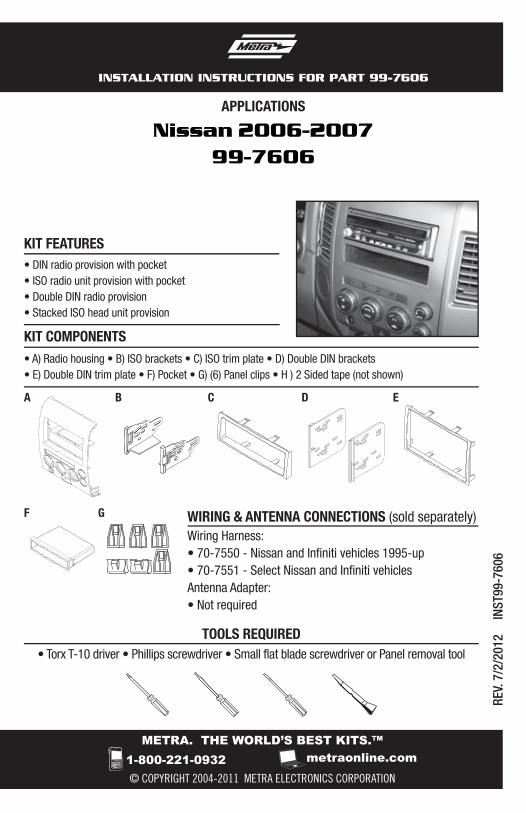
APPLICATIONS
1-800-221-0932 metraonline.com
INSTALLATION INSTRUCTIONS FOR PART 99-7606
REV.
7/2
/201
2 IN
ST99
-760
6
WIRING & ANTENNA CONNECTIONS (sold separately) Wiring Harness:• 70-7550 - Nissan and Infiniti vehicles 1995-up • 70-7551 - Select Nissan and Infiniti vehiclesAntenna Adapter:• Not required
• Torx T-10 driver • Phillips screwdriver • Small flat blade screwdriver or Panel removal tool
TOOLS REQUIRED
Nissan 2006-200799-7606
• A) Radio housing • B) ISO brackets • C) ISO trim plate • D) Double DIN brackets • E) Double DIN trim plate • F) Pocket • G) (6) Panel clips • H ) 2 Sided tape (not shown)
KIT FEATURES
KIT COMPONENTS
B CA
• DIN radio provision with pocket • ISO radio unit provision with pocket• Double DIN radio provision• Stacked ISO head unit provision
D E
GF
Table of Contents
Dash Disassembly
– Nissan Titan 2006-2007 (with dual zone climate controls) .................................................3-4
– Nissan Pathfinder Armada 2006-2007 ...........................................................................3-4
Pre-Kit Assembly ............................................................................................................... 5
Kit Assembly
– DIN radio provision with pocket ...................................................................................... 6
– ISO radio provision with pocket ...................................................................................... 7
– Double DIN radio provision .............................................................................................. 8
– Stacked ISO head unit provision ...................................................................................... 9
KNOWLEDGE IS POWEREnhance your installation and fabrication skills by enrolling in the most recognized and respected mobile electronics school in our industry.Log onto www.installerinstitute.com or call 800-354-6782 for more information and take steps toward a better tomorrow.
Metra recommends MECP certified technicians
99-7606
CAUTION: Metra recommends disconnecting the negative battery terminal before beginning any installation. All accessories, switches, and especially air bag indicator lights must be plugged in before reconnecting the battery or cycling the ignition.
Note: Refer to the instructions included with the aftermarket radio.
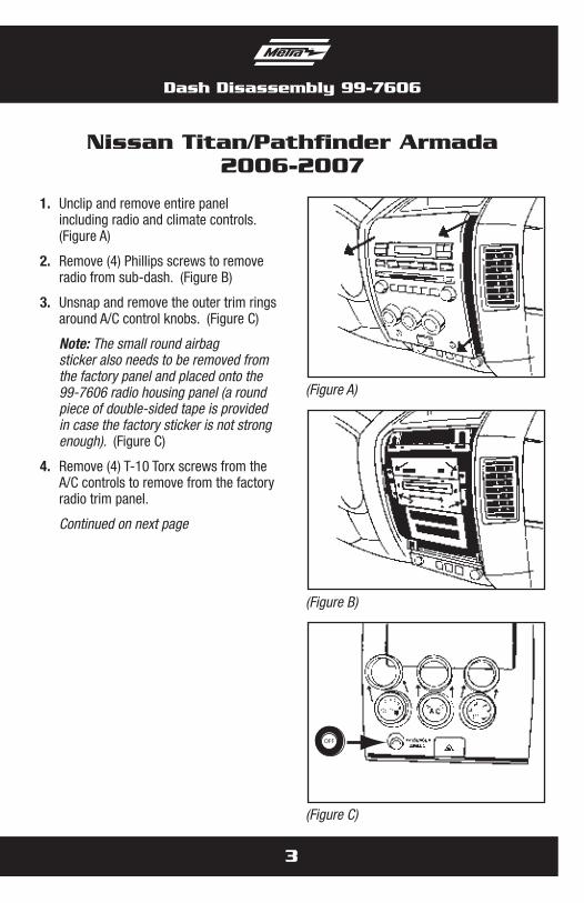
1. Unclip and remove entire panel including radio and climate controls. (Figure A)
2. Remove (4) Phillips screws to remove radio from sub-dash. (Figure B)
3. Unsnap and remove the outer trim rings around A/C control knobs. (Figure C)
Note: The small round airbag sticker also needs to be removed from the factory panel and placed onto the 99-7606 radio housing panel (a round piece of double-sided tape is provided in case the factory sticker is not strong enough). (Figure C)
4. Remove (4) T-10 Torx screws from the A/C controls to remove from the factory radio trim panel.
Continued on next page
3
Nissan Titan/Pathfinder Armada2006-2007
Dash Disassembly 99-7606
(Figure A)
OFF
(Figure C)
(Figure B)
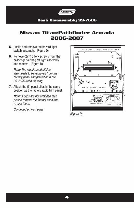
5. Unclip and remove the hazard light switch assembly. (Figure D)
6. Remove (2) T10 Torx screws from the passenger air bag off light assembly and remove. (Figure D)
Note: The small round sticker also needs to be removed from the factory panel and placed onto the 99-7606 radio housing.
7. Attach the (6) panel clips in the same position as the factory radio trim panel.
Note: If clips are not provided then please remove the factory clips and re-use them.
Continued on next page
4
Nissan Titan/Pathfinder Armada2006-2007
Dash Disassembly 99-7606
CLIP
HAZARD SWITCH
PASSENGER AIR BAG LIGHT
T-10 TORX SCREW
T-10 TORX SCREW
A/C CONTROL PANEL
INSIDE VIEW - RADIO TRIM PANEL BACK
1
2
3
4
T-10 TORX SCREWS
T-10 TORX SCREWS
1 2
(Figure D)
5
Pre-Kit Assembly 99-7606
Nissan Titan/Pathfinder Armada2006-2007
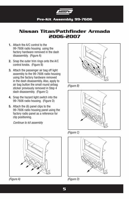
1. Attach the A/C control to the 99-7606 radio housing using the factory hardware removed in the dash disassembly. (Figure A)
2. Snap the outer trim rings onto the A/C control knobs. (Figure B)
3. Attach the passenger air bag off light assembly to the 99-7606 radio housing using the factory hardware removed in the dash disassembly. Also, apply to air bag button the small round airbag sticker previously removed in Step 4 dash disassembly. (Figure C)
4. Snap the hazard light switch into the 99-7606 radio housing. (Figure D)
5. Attach the (6) panel clips to the 99-7606 radio housing panel using the factory radio panel as a reference for clip positioning.
Continue to kit assembly
A/C
12
34
0
12
34
0
MAX A/C
RR
R
(Figure B)
A/COFF
12
34
0
12
34
0
MAX A/C
RR
R
(Figure D)
A/COFF
12
34
0
12
34
0
MAX A/C
RR
R
(Figure C)
A/C
12
34
0
12
34
0
MAX A/C
RR
R
(Figure A)
6
Kit Assembly 99-7606
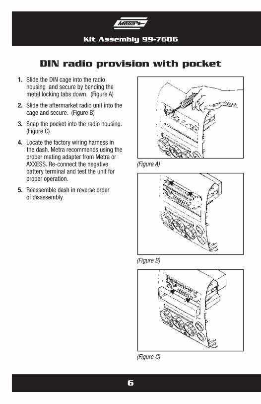
1. Slide the DIN cage into the radio housing and secure by bending the metal locking tabs down. (Figure A)
2. Slide the aftermarket radio unit into the cage and secure. (Figure B)
3. Snap the pocket into the radio housing. (Figure C)
4. Locate the factory wiring harness in the dash. Metra recommends using the proper mating adapter from Metra or AXXESS. Re-connect the negative battery terminal and test the unit for proper operation.
5. Reassemble dash in reverse order of disassembly.
DIN radio provision with pocket
(Figure A)
(Figure C)
(Figure B)
Kit Assembly 99-7606
7
ISO radio provision with pocket
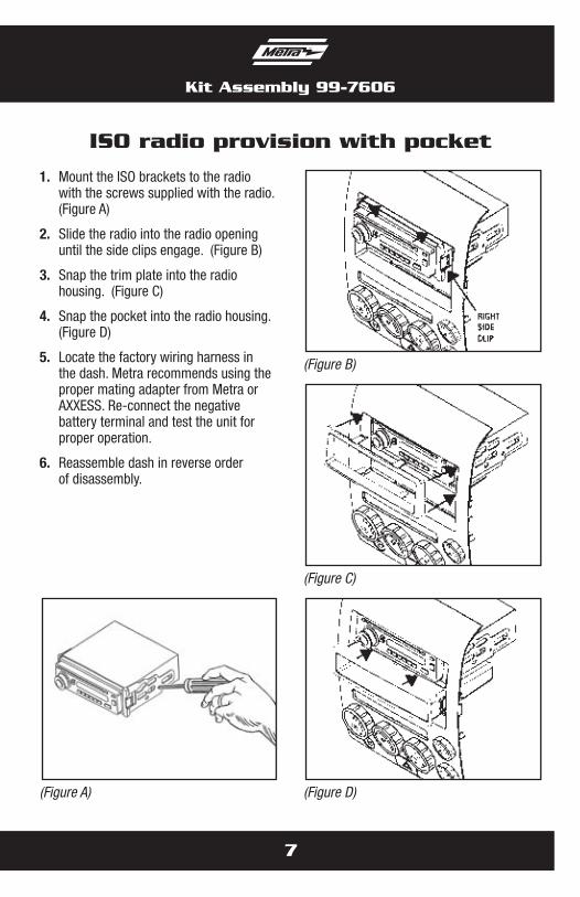
1. Mount the ISO brackets to the radio with the screws supplied with the radio. (Figure A)
2. Slide the radio into the radio opening until the side clips engage. (Figure B)
3. Snap the trim plate into the radio housing. (Figure C)
4. Snap the pocket into the radio housing. (Figure D)
5. Locate the factory wiring harness in the dash. Metra recommends using the proper mating adapter from Metra or AXXESS. Re-connect the negative battery terminal and test the unit for proper operation.
6. Reassemble dash in reverse order of disassembly.
(Figure B)
(Figure D)
(Figure C)
(Figure A)
Kit Assembly 99-7606
8
Double DIN radio unit provision
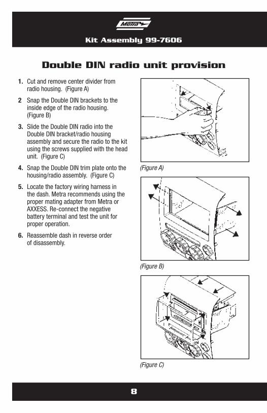
1. Cut and remove center divider from radio housing. (Figure A)
2 Snap the Double DIN brackets to the inside edge of the radio housing. (Figure B)
3. Slide the Double DIN radio into the Double DIN bracket/radio housing assembly and secure the radio to the kit using the screws supplied with the head unit. (Figure C)
4. Snap the Double DIN trim plate onto the housing/radio assembly. (Figure C)
5. Locate the factory wiring harness in the dash. Metra recommends using the proper mating adapter from Metra or AXXESS. Re-connect the negative battery terminal and test the unit for proper operation.
6. Reassemble dash in reverse order of disassembly.
(Figure A)
(Figure C)
(Figure B)
Kit Assembly 99-7606
9
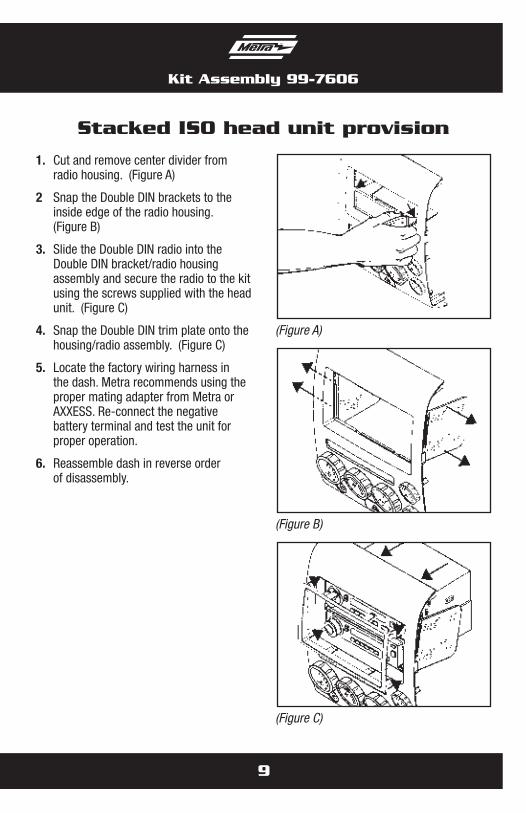
Stacked ISO head unit provision
1. Cut and remove center divider from radio housing. (Figure A)
2 Snap the Double DIN brackets to the inside edge of the radio housing. (Figure B)
3. Slide the Double DIN radio into the Double DIN bracket/radio housing assembly and secure the radio to the kit using the screws supplied with the head unit. (Figure C)
4. Snap the Double DIN trim plate onto the housing/radio assembly. (Figure C)
5. Locate the factory wiring harness in the dash. Metra recommends using the proper mating adapter from Metra or AXXESS. Re-connect the negative battery terminal and test the unit for proper operation.
6. Reassemble dash in reverse order of disassembly.
(Figure A)
(Figure C)
(Figure B)

Notes

Notes

METRA. THE WORLD’S BEST KITS.™
© COPYRIGHT 2004-2011 METRA ELECTRONICS CORPORATION 1-800-221-0932 metraonline.com
INSTALLATION INSTRUCTIONS FOR PART 99-7606
REV.
7/2
/201
2 IN
ST99
-760
6
METRA. THE WORLD’S BEST KITS.™
© COPYRIGHT 2004-2011 METRA ELECTRONICS CORPORATION
APLICACIONES
1-800-221-0932 metraonline.com
INSTRUCCIONES DE INSTALACIÓN PARA LA PIEZA 99-7606
REV.
7/1
0/20
12
INS
T99-
7606
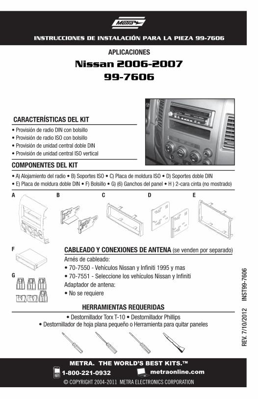
• Destornillador Torx T-10 • Destornillador Phillips• Destornillador de hoja plana pequeño o Herramienta para quitar paneles
HERRAMIENTAS REQUERIDAS
Nissan 2006-200799-7606
• A) Alojamiento del radio • B) Soportes ISO • C) Placa de moldura ISO • D) Soportes doble DIN • E) Placa de moldura doble DIN • F) Bolsillo • G) (6) Ganchos del panel • H ) 2-cara cinta (no mostrado)
CARACTERÍSTICAS DEL KIT
COMPONENTES DEL KIT
B CA
• Provisión de radio DIN con bolsillo • Provisión de radio ISO con bolsillo• Provisión de unidad central doble DIN• Provisión de unidad central ISO vertical
CABLEADO Y CONEXIONES DE ANTENA (se venden por separado)Arnés de cableado:• 70-7550 - Vehículos Nissan y Infiniti 1995 y mas• 70-7551 - Seleccione los vehículos Nissan y InfinitiAdaptador de antena:• No se requiere
D E
G
F
Indice
Desmontaje del tablero
– Nissan Titan 2006-2007 (con controles de clima de zona dual) ..........................................3-4
– Nissan Pathfinder Armada 2006-2007 ...........................................................................3-4
Pre-Ensamble del kit ......................................................................................................... 5
Ensamble del kit
– Provisión de radio DIN con bolsillo .................................................................................... 6
– Provisión de radio ISO con bolsillo .................................................................................... 7
– Provisión de unidad central doble DIN ............................................................................... 8
– Provisión de unidad central ISO vertical ............................................................................ 9
99-7606
PRECAUCIÓN: Metra recomienda desconectar el terminal negativo de la batería antes de comenzar cualquier instalación. Todos los accesorios, interruptores y, especialmente, las luces indicadoras de airbag deben estar enchufados antes de volver a conectar la batería o comenzar el ciclo de ignición.
Nota: Remítase a las instrucciones incluidas con el radio de posventa.
KNOWLEDGE IS POWEREnhance your installation and fabrication skills by enrolling in the most recognized and respected mobile electronics school in our industry.Log onto www.installerinstitute.com or call 800-354-6782 for more information and take steps toward a better tomorrow.
Metra recomienda técnicos con certificación del Programa de Certificación en Electrónica Móvil (Mobile Electronics Certification Program, MECP).
EL CONOCIMIENTO ES PODERMejore sus habilidades de instalación y fabricación inscribiéndose en la escuela de dispositivos electrónicos móviles más reconocida y respetada de nuestra industria. Regístrese en www.installerinstitute.com o llame al 800-354-6782 para obtener más información y avance hacia un futuro mejor.
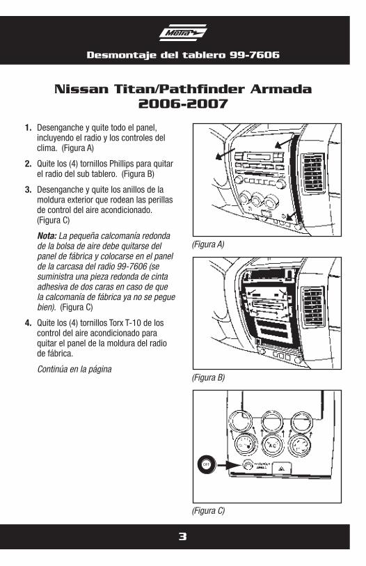
1. Desenganche y quite todo el panel, incluyendo el radio y los controles del clima. (Figura A)
2. Quite los (4) tornillos Phillips para quitar el radio del sub tablero. (Figura B)
3. Desenganche y quite los anillos de la moldura exterior que rodean las perillas de control del aire acondicionado. (Figura C)
Nota: La pequeña calcomanía redonda de la bolsa de aire debe quitarse del panel de fábrica y colocarse en el panel de la carcasa del radio 99-7606 (se suministra una pieza redonda de cinta adhesiva de dos caras en caso de que la calcomanía de fábrica ya no se pegue bien). (Figura C)
4. Quite los (4) tornillos Torx T-10 de los control del aire acondicionado para quitar el panel de la moldura del radio de fábrica.
Continúa en la página
3
Nissan Titan/Pathfinder Armada2006-2007
Desmontaje del tablero 99-7606
(Figura A)
OFF
(Figura C)
(Figura B)
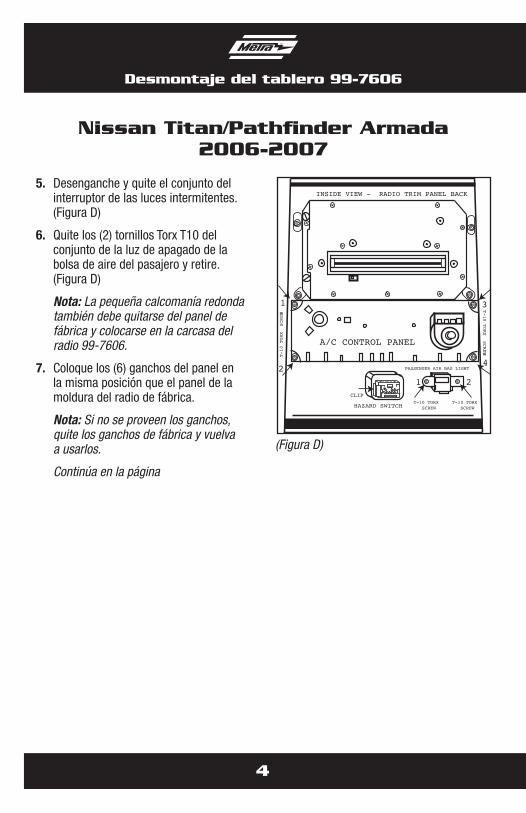
5. Desenganche y quite el conjunto del interruptor de las luces intermitentes. (Figura D)
6. Quite los (2) tornillos Torx T10 del conjunto de la luz de apagado de la bolsa de aire del pasajero y retire. (Figura D)
Nota: La pequeña calcomanía redonda también debe quitarse del panel de fábrica y colocarse en la carcasa del radio 99-7606.
7. Coloque los (6) ganchos del panel en la misma posición que el panel de la moldura del radio de fábrica.
Nota: Si no se proveen los ganchos, quite los ganchos de fábrica y vuelva a usarlos.
Continúa en la página
4
Nissan Titan/Pathfinder Armada2006-2007
Desmontaje del tablero 99-7606
CLIP
HAZARD SWITCH
PASSENGER AIR BAG LIGHT
T-10 TORX SCREW
T-10 TORX SCREW
A/C CONTROL PANEL
INSIDE VIEW - RADIO TRIM PANEL BACK
1
2
3
4
T-10 TORX SCREWS
T-10 TORX SCREWS
1 2
(Figura D)
5
Pre-Ensamble del kit 99-7606
Nissan Titan/Pathfinder Armada2006-2007
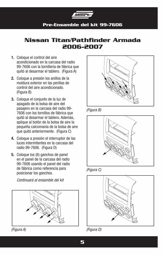
1. Coloque el control del aire acondicionado en la carcasa del radio 99-7606 con la tornillería de fábrica que quitó al desarmar el tablero. (Figura A)
2. Coloque a presión los anillos de la moldura exterior en las perillas de control del aire acondicionado. (Figura B)
3. Coloque el conjunto de la luz de apagado de la bolsa de aire del pasajero en la carcasa del radio 99-7606 con los tornillos de fábrica que quitó al desarmar el tablero. Además, aplique al botón de la bolsa de aire la pequeña calcomanía de la bolsa de aire que quitó anteriormente. (Figura C)
4. Coloque a presión el interruptor de las luces intermitentes en la carcasa del radio 99-7606. (Figura D)
5. Coloque los (6) ganchos de panel en el panel de la carcasa del radio 99-7606 usando el panel del radio de fábrica como referencia para posicionar los ganchos.
Continuará al ensamble del kit
A/C
12
34
0
12
34
0
MAX A/C
RR
R
(Figura B)
A/COFF
12
34
0
12
34
0
MAX A/C
RR
R
(Figura D)
A/COFF
12
34
0
12
34
0
MAX A/C
RR
R
(Figura C)
A/C
12
34
0
12
34
0
MAX A/C
RR
R
(Figura A)
6
Ensamble del kit 99-7606
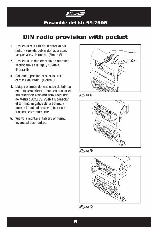
1. Deslice la reja DIN en la carcasa del radio y sujétela doblando hacia abajo las pestañas de metal. (Figura A)
2. Deslice la unidad de radio de mercado secundario en la reja y sujétela. (Figura B)
3. Coloque a presión el bolsillo en la carcasa del radio. (Figura C)
4. Ubique el arnés del cableado de fábrica en el tablero. Metra recomienda usar el adaptador de acoplamiento adecuado de Metra o AXXESS. Vuelva a conectar el terminal negativo de la batería y pruebe la unidad para verificar que funcione correctamente.
5. Vuelva a montar el tablero en forma inversa al desmontaje.
DIN radio provision with pocket
(Figura A)
(Figura C)
(Figura B)
Ensamble del kit 99-7606
7
ISO radio provision with pocket
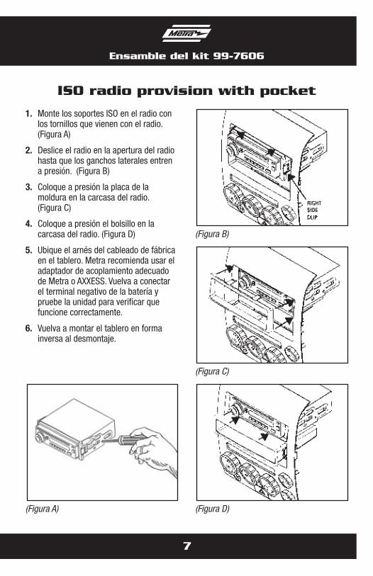
1. Monte los soportes ISO en el radio con los tornillos que vienen con el radio. (Figura A)
2. Deslice el radio en la apertura del radio hasta que los ganchos laterales entren a presión. (Figura B)
3. Coloque a presión la placa de la moldura en la carcasa del radio. (Figura C)
4. Coloque a presión el bolsillo en la carcasa del radio. (Figura D)
5. Ubique el arnés del cableado de fábrica en el tablero. Metra recomienda usar el adaptador de acoplamiento adecuado de Metra o AXXESS. Vuelva a conectar el terminal negativo de la batería y pruebe la unidad para verificar que funcione correctamente.
6. Vuelva a montar el tablero en forma inversa al desmontaje.
(Figura B)
(Figura D)
(Figura C)
(Figura A)
Ensamble del kit 99-7606
8
Double DIN radio unit provision
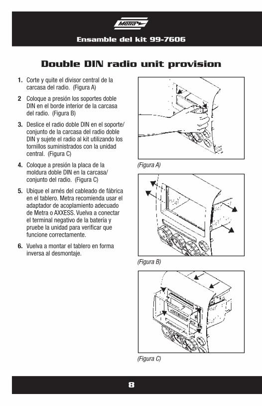
1. Corte y quite el divisor central de la carcasa del radio. (Figura A)
2 Coloque a presión los soportes doble DIN en el borde interior de la carcasa del radio. (Figura B)
3. Deslice el radio doble DIN en el soporte/conjunto de la carcasa del radio doble DIN y sujete el radio al kit utilizando los tornillos suministrados con la unidad central. (Figura C)
4. Coloque a presión la placa de la moldura doble DIN en la carcasa/conjunto del radio. (Figura C)
5. Ubique el arnés del cableado de fábrica en el tablero. Metra recomienda usar el adaptador de acoplamiento adecuado de Metra o AXXESS. Vuelva a conectar el terminal negativo de la batería y pruebe la unidad para verificar que funcione correctamente.
6. Vuelva a montar el tablero en forma inversa al desmontaje.
(Figura A)
(Figura C)
(Figura B)
Ensamble del kit 99-7606
9
Stacked ISO head unit provision
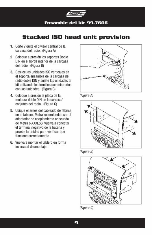
1. Corte y quite el divisor central de la carcasa del radio. (Figura A)
2 Coloque a presión los soportes Doble DIN en el borde interior de la carcasa del radio. (Figura B)
3. Deslice las unidades ISO verticales en el soporte/ensamble de la carcasa del radio doble DIN y sujete las unidades al kit utilizando los tornillos suministrados con las unidades. (Figura C)
4. Coloque a presión la placa de la moldura doble DIN en la carcasa/conjunto del radio. (Figura C)
5. Ubique el arnés del cableado de fábrica en el tablero. Metra recomienda usar el adaptador de acoplamiento adecuado de Metra o AXXESS. Vuelva a conectar el terminal negativo de la batería y pruebe la unidad para verificar que funcione correctamente.
6. Vuelva a montar el tablero en forma inversa al desmontaje.
(Figura A)
(Figura C)
(Figura B)

Notas

Notas

METRA. THE WORLD’S BEST KITS.™
© COPYRIGHT 2004-2011 METRA ELECTRONICS CORPORATION 1-800-221-0932 metraonline.com
INSTRUCCIONES DE INSTALACIÓN PARA LA PIEZA 99-7606
REV.
7/1
0/20
12
INS
T99-
7606