Embed Size (px)
Citation preview
IP-Intercom
Project name: IP-Intercom
Application abcl_ip_intercom_vb0113_20140912
Document revision: 1.4
Date: 12.09.2014
Author: Jagdeesh Pal
Application User Manual
© 2014 Barix AG, all rights reserved. All information is subject to change without notice. All mentioned trademarks belong to their respective owners and are used for reference only.
IP-Intercom Application User Manual
Table of Content
1 Introduction................................................................................................................................................. 4
1.1 About this document .................................................................................................................................4
1.2 Features..................................................................................................................................................... 4
1.3 System overview........................................................................................................................................ 5
2 Quick Start Guide........................................................................................................................................5
2.1 Connecting an Annuncicom 100 device.....................................................................................................5 2.1.1 STEP 1....................................................................................................................................................................................... 6 2.1.2 STEP 2....................................................................................................................................................................................... 6 2.1.3 STEP 3....................................................................................................................................................................................... 6 2.1.4 STEP 4....................................................................................................................................................................................... 6
2.2 Configuring IP-intercom.............................................................................................................................6
2.3 Initiating communication.............................................................................................................................8
3 User Interface.............................................................................................................................................. 9
3.1 HOME...................................................................................................................................................... 10
3.2 PROFILES............................................................................................................................................... 12
3.3 CONFIGURATION (ADVANCED )...........................................................................................................12 3.3.1 NETWORK SETTINGS...................................................................................................................................................... 13 3.3.2 STREAMING......................................................................................................................................................................... 15 3.3.3 AUDIO................................................................................................................................................................................... 17 3.3.4 CONTROL INTERFACES................................................................................................................................................. 19 3.3.5 SERIAL GATEWAY............................................................................................................................................................. 20 3.3.6 SECURITY............................................................................................................................................................................. 22
3.4 STATUS................................................................................................................................................... 23
3.5 DEFAULTS.............................................................................................................................................. 26
3.6 UPDATE................................................................................................................................................... 27 3.6.1 Updating a device using the web UI................................................................................................................................. 27 3.6.2 Updating the device using the RS-232 serial port.........................................................................................................28
3.7 REBOOT.................................................................................................................................................. 29
4 Configuration Parameters........................................................................................................................30
4.1 EEPROM setup parameters and default values......................................................................................30
5 Advanced Use of the IP-intercom............................................................................................................34
5.1 Command Interface..................................................................................................................................34 5.1.1 Command interface Protocol............................................................................................................................................ 34 5.1.2 List of commands................................................................................................................................................................. 35
5.2 Discovering Devices.................................................................................................................................40
5.3 CGI WEB interface................................................................................................................................... 40 5.3.1 rc.cgi........................................................................................................................................................................................ 40 5.3.2 setup.cgi.................................................................................................................................................................................. 41 5.3.3 BAS.cgi ................................................................................................................................................................................... 42
5.4 Serial gateway.......................................................................................................................................... 42
5.5 SNMP TRAPS.......................................................................................................................................... 44
2 / 49
IP-Intercom Application User Manual
5.6 Streaming................................................................................................................................................. 44
5.7 Receiving Stream.....................................................................................................................................45
5.8 Status Change Monitoring........................................................................................................................46
5.9 Play a MP3 from ROM/USB file system...................................................................................................46
5.10 Syslog message.....................................................................................................................................46
5.11 BCL Application......................................................................................................................................47
5.12 Using AiPhone.......................................................................................................................................47
6 Acceptance Reviews and Approvals.......................................................................................................49
7 Document management...........................................................................................................................49
Index of TablesTable 1: EEPROM Settings.................................................................................................................................................33Table 2: Supported Commands..........................................................................................................................................39Table 3: CGI WEB Interfaces..............................................................................................................................................40Table 4: rc.cgi Commands ................................................................................................................................................. 41Table 5: Serial Gateway Protocols......................................................................................................................................42Table 6: Serial Port Settings...............................................................................................................................................43Table 7: Supported systems for the local playback.............................................................................................................46
3 / 49
IP-Intercom Application User Manual
1 Introduction
1.1 About this document
This document is describing the configuration, supported communication protocols and default settings of the IP-intercom BCL application.
The IP-intercom application is the successor of former ABCL Annuncicom full-duplex FW from BARIX, providing in addition many enhancements and new features. The most important improvements include:
• command interface for setting audio and communication parameters dynamically;
• using the BCL LINK command for better quality and low latency of the audio;
• an improved and user friendly version of the WEB UI.
A full list of all supported features is given below.
1.2 Features
• Stream audio to unicast/broadcast/multicast destinations.
• TCP/UDP command interface to control the device remotely.
• Serial gateway for tunneling serial data to network and vice versa.
• Sending SNMP traps on IO/Relay state change.
• Audio playback from unicast/broadcast/multicast source.
• Sending syslog messages to remote host.
• Interface to discover devices running ip-intercom.
• Play a mp3 audio file from USB/FLASH file system.
• CGI WEB interface to update application variables and EEPROM settings.
4 / 49
IP-Intercom Application User Manual
1.3 System overview
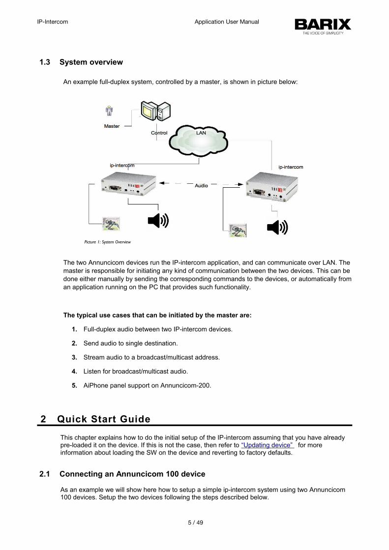
An example full-duplex system, controlled by a master, is shown in picture below:
The two Annuncicom devices run the IP-intercom application, and can communicate over LAN. The master is responsible for initiating any kind of communication between the two devices. This can be done either manually by sending the corresponding commands to the devices, or automatically froman application running on the PC that provides such functionality.
The typical use cases that can be initiated by the master are:
1. Full-duplex audio between two IP-intercom devices.
2. Send audio to single destination.
3. Stream audio to a broadcast/multicast address.
4. Listen for broadcast/multicast audio.
5. AiPhone panel support on Annuncicom-200.
2 Quick Start Guide
This chapter explains how to do the initial setup of the IP-intercom assuming that you have already pre-loaded it on the device. If this is not the case, then refer to “Updating device” for more information about loading the SW on the device and reverting to factory defaults.
2.1 Connecting an Annuncicom 100 device
As an example we will show here how to setup a simple ip-intercom system using two Annuncicom 100 devices. Setup the two devices following the steps described below.
5 / 49
Picture 1: System Overview
IP-Intercom Application User Manual
2.1.1 STEP 1
Plug a standard (straight) network cable into the LAN port of the Annuncicom and the other end into your switch connected to your LAN.
2.1.2 STEP 2
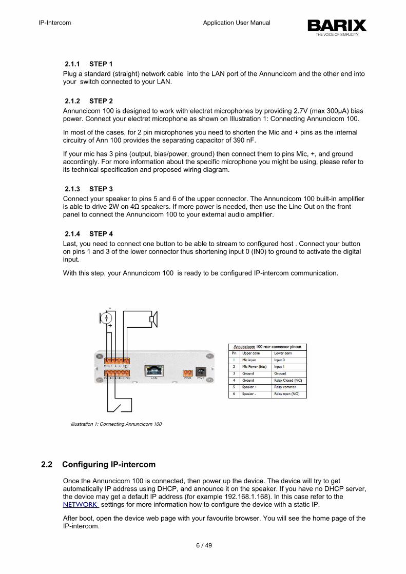
Annuncicom 100 is designed to work with electret microphones by providing 2.7V (max 300μA) bias power. Connect your electret microphone as shown on Illustration 1: Connecting Annuncicom 100.
In most of the cases, for 2 pin microphones you need to shorten the Mic and + pins as the internal circuitry of Ann 100 provides the separating capacitor of 390 nF.
If your mic has 3 pins (output, bias/power, ground) then connect them to pins Mic, +, and ground accordingly. For more information about the specific microphone you might be using, please refer to its technical specification and proposed wiring diagram.
2.1.3 STEP 3
Connect your speaker to pins 5 and 6 of the upper connector. The Annuncicom 100 built-in amplifier is able to drive 2W on 4Ω speakers. If more power is needed, then use the Line Out on the front panel to connect the Annuncicom 100 to your external audio amplifier.
2.1.4 STEP 4
Last, you need to connect one button to be able to stream to configured host . Connect your button on pins 1 and 3 of the lower connector thus shortening input 0 (IN0) to ground to activate the digital input.
With this step, your Annuncicom 100 is ready to be configured IP-intercom communication.
2.2 Configuring IP-intercom
Once the Annuncicom 100 is connected, then power up the device. The device will try to get automatically IP address using DHCP, and announce it on the speaker. If you have no DHCP server,the device may get a default IP address (for example 192.168.1.168). In this case refer to the NETWORK settings for more information how to configure the device with a static IP.
After boot, open the device web page with your favourite browser. You will see the home page of theIP-intercom.
6 / 49
Illustration 1: Connecting Annuncicom 100
IP-Intercom Application User Manual
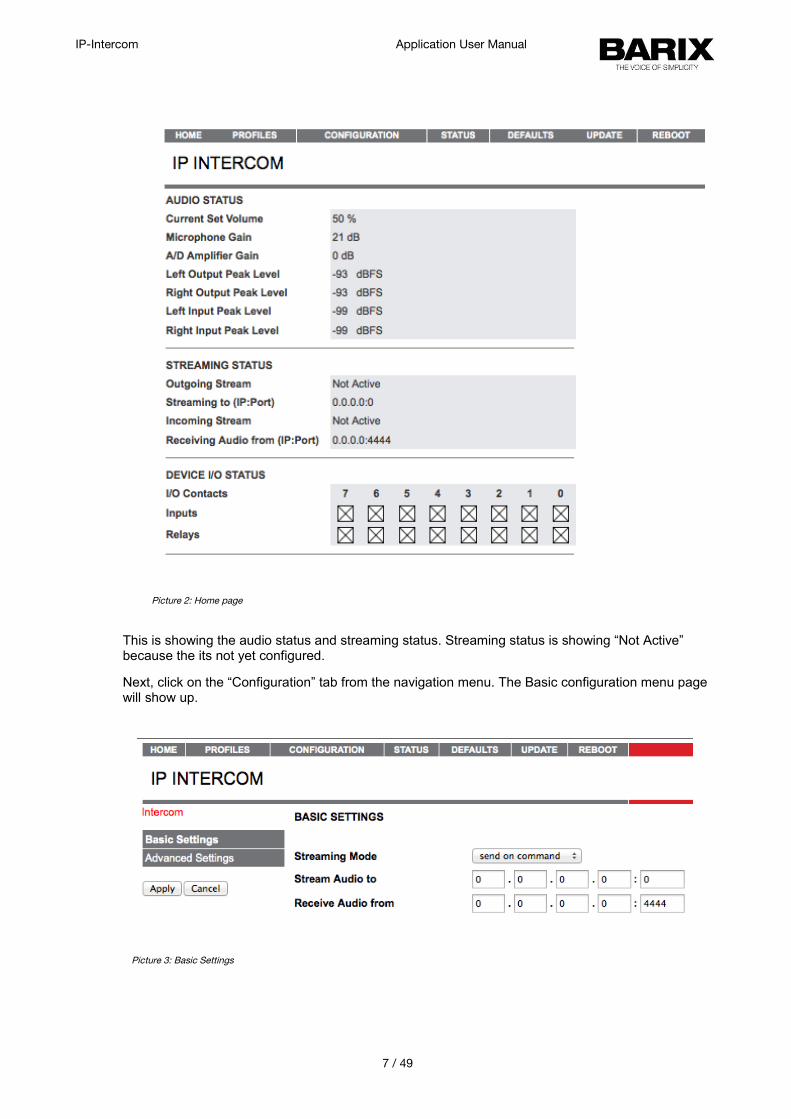
This is showing the audio status and streaming status. Streaming status is showing “Not Active” because the its not yet configured.
Next, click on the “Configuration” tab from the navigation menu. The Basic configuration menu page will show up.
7 / 49
Picture 2: Home page
Picture 3: Basic Settings
IP-Intercom Application User Manual
This web page provides the interface to make the device working with bare minimum configuration. All other configurations are taken as default. More parameter can be set from advanced configuration settings tab.
• Streaming mode "send always" will stream always to the configured destination. If not configured, no audio isstreamed."send on I0/DI1" will stream if the I0 (Annuncicom100/Legacy) or DI1 (Annuncicom1000 / Exstreamer1000 ) is activated.
Default:"send on I0/DI1"
• Stream Audio to IP:PortSet the IP address and the port of the destination where you want to stream the audio. The destination IP could be unicast, multicast, broadcast address. Sending the stream can be disabled by setting IP and port to 0.
Default: "0.0.0.0:0"
• Receive Audio from IP:PortSet the source IP and port from where audio shall be accepted. Source IP could be unicast,multicast cast address. Set the source IP address to 0.0.0.0 to receive broadcast audio.
Default: "0.0.0.0:4444"
2.3 Initiating communication
This section will describe an example to start IP-intercom communication between two devices as depicted in “System Overview”. Commands used here are described in section Command Interface of this document.
Devices are set to stream on IO so that they will not start streaming until the reception of start streaming command or button is pressed. For example, as a result of following the steps in the previous two sections we may have two devices already setup:
• device A (ip 192.168.11.209)
• device B(ip 192.168.11.208)
The following steps describe how the user can initiate the communication between these two devices:
1. Open terminal on PC. Use telnet command to connect to the command interface of the device A:
$telnet 192.168.11.208 12302 <CR>
2. Set the streaming destination and port:
c=77&ip=192.168.11.208&port=3030 <CR>
3. Open another terminal on PC. Use telnet command to connect to the command interface ofthe device B as shown in step 1 for device A.
4. Listening audio source on the device B:
8 / 49
IP-Intercom Application User Manual
c=76&ip=192.168.11.209&port=3030 <CR>
5. Start streaming from device A by typing command below in respective terminal:
c=83 <CR>
6. To Stop streaming send command:
c=84 <CR>
3 User Interface
WEB user interface consist of the following web pages:
1. Home
Main web page of the device. It shows the current status and few configuration parameters.
2. Profile
Selects the profile to be used by the device. At the moment only one profile is supported.
3. Configuration
This is the configuration web page of the device. It has two sections - basic settings, and advanced settings.
4. Status
This web page shows the current status/values of the configured parameters. Some parameters can be changed dynamically and are reflected by this page.
5. Defaults
The web page to restore the factory default settings.
6. Update
The web page to update the firmware and applications.
7. Reboot
The web page to reboot and select default application. The values of dynamic parameters will lost and system will start with their default values stored in EEPROM.
To get detailed description of the above web pages, refer to later sections of this chapter.
9 / 49
IP-Intercom Application User Manual
3.1 HOME
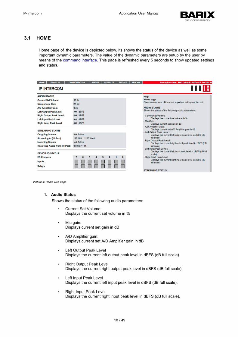
Home page of the device is depicted below. Its shows the status of the device as well as some important dynamic parameters. The value of the dynamic parameters are setup by the user by means of the command interface. This page is refreshed every 5 seconds to show updated settings and status.
1. Audio Status
Shows the status of the following audio parameters:
• Current Set Volume: Displays the current set volume in %
• Mic gain: Displays current set gain in dB
• A/D Amplifier gain: Displays current set A/D Amplifier gain in dB
• Left Output Peak Level Displays the current left output peak level in dBFS (dB full scale)
• Right Output Peak Level Displays the current right output peak level in dBFS (dB full scale)
• Left Input Peak Level Displays the current left input peak level in dBFS (dB full scale).
• Right Input Peak Level Displays the current right input peak level in dBFS (dB full scale).
10 / 49
Picture 4: Home web page
IP-Intercom Application User Manual
2. Streaming Status
Shows the status of the following audio parameters:• Outgoing Stream :
Displays the status of outgoing stream. Whether that is active or not.
• Streaming to (IP:Port) : Displays current set destination for outgoing stream.
• Incoming Stream : Displays the status of incoming stream. Whether device is receiving any audio or not.
• Receiving Audio from(IP:Port) :Displays current set audio source to receive audio.
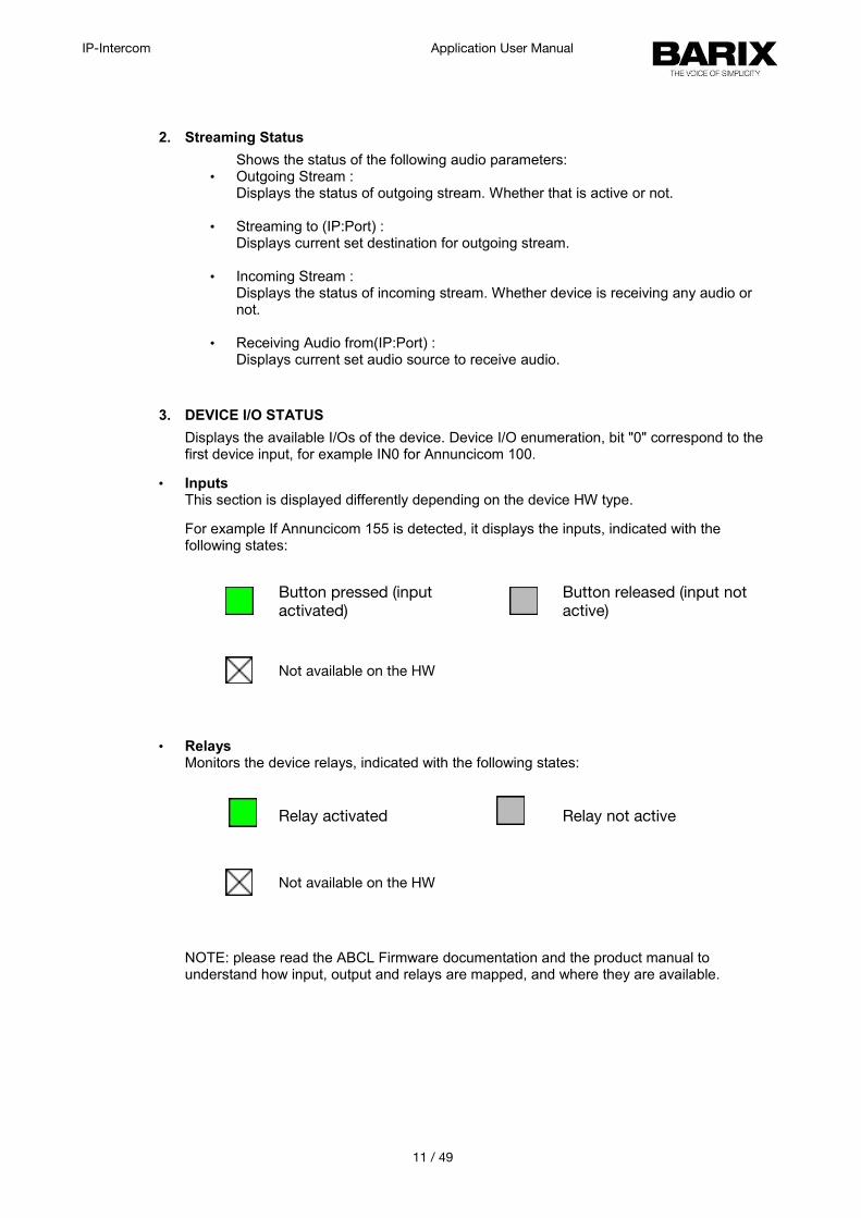
3. DEVICE I/O STATUS
Displays the available I/Os of the device. Device I/O enumeration, bit "0" correspond to the first device input, for example IN0 for Annuncicom 100.
• InputsThis section is displayed differently depending on the device HW type.
For example If Annuncicom 155 is detected, it displays the inputs, indicated with the following states:
Button pressed (input activated)
Button released (input not active)
Not available on the HW
• RelaysMonitors the device relays, indicated with the following states:
Relay activated Relay not active
Not available on the HW
NOTE: please read the ABCL Firmware documentation and the product manual to understand how input, output and relays are mapped, and where they are available.
11 / 49
IP-Intercom Application User Manual
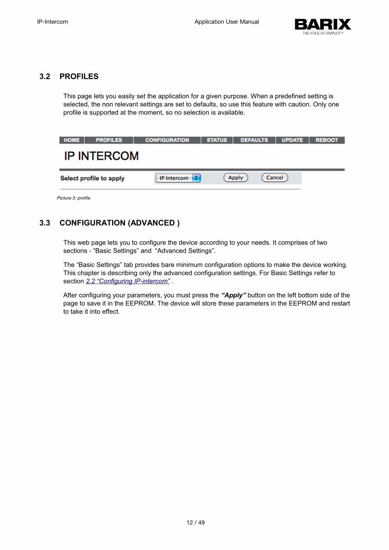
3.2 PROFILES
This page lets you easily set the application for a given purpose. When a predefined setting is selected, the non relevant settings are set to defaults, so use this feature with caution. Only one profile is supported at the moment, so no selection is available.
3.3 CONFIGURATION (ADVANCED )
This web page lets you to configure the device according to your needs. It comprises of two sections - “Basic Settings” and “Advanced Settings”.
The “Basic Settings” tab provides bare minimum configuration options to make the device working. This chapter is describing only the advanced configuration settings. For Basic Settings refer to section 2.2 “Configuring IP-intercom” .
After configuring your parameters, you must press the “Apply” button on the left bottom side of the page to save it in the EEPROM. The device will store these parameters in the EEPROM and restart to take it into effect.
12 / 49
Picture 5: profile
IP-Intercom Application User Manual
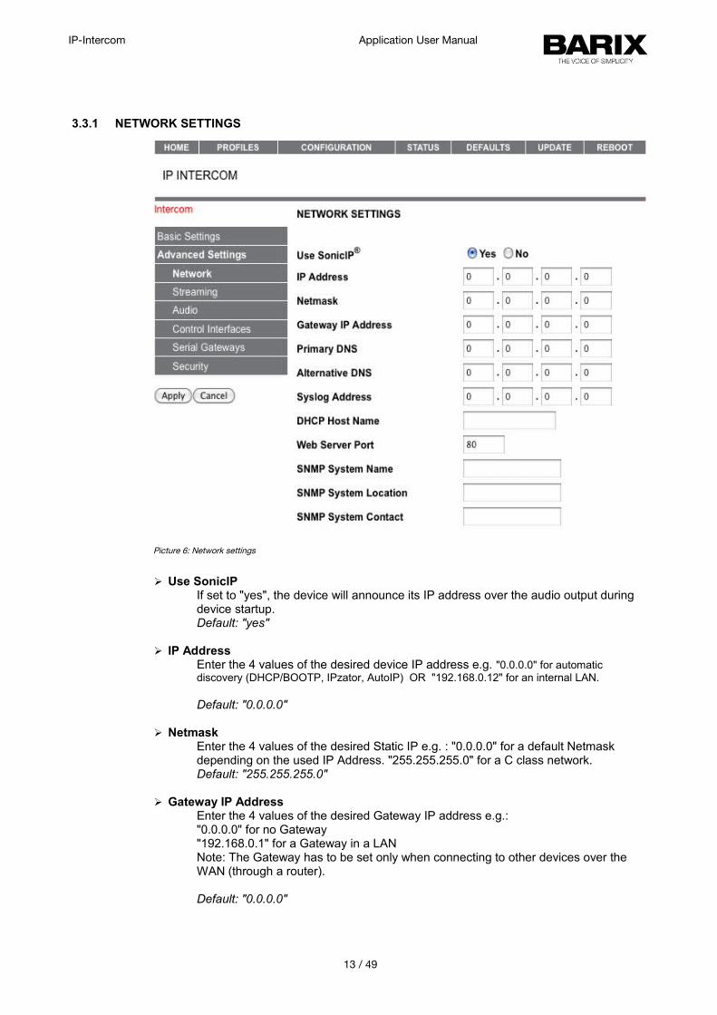
3.3.1 NETWORK SETTINGS
➢ Use SonicIPIf set to "yes", the device will announce its IP address over the audio output during device startup. Default: "yes"
➢ IP AddressEnter the 4 values of the desired device IP address e.g. "0.0.0.0" for automatic discovery (DHCP/BOOTP, IPzator, AutoIP) OR "192.168.0.12" for an internal LAN.
Default: "0.0.0.0"
➢ NetmaskEnter the 4 values of the desired Static IP e.g. : "0.0.0.0" for a default Netmask depending on the used IP Address. "255.255.255.0" for a C class network.Default: "255.255.255.0"
➢ Gateway IP AddressEnter the 4 values of the desired Gateway IP address e.g.:"0.0.0.0" for no Gateway"192.168.0.1" for a Gateway in a LANNote: The Gateway has to be set only when connecting to other devices over the WAN (through a router).
Default: "0.0.0.0"
13 / 49
Picture 6: Network settings
IP-Intercom Application User Manual
➢ Primary DNSIn this field you can give the desired primary and alternative DNS IP address to be able to connect to URLs (e.g. www.radio.com).Default: "0.0.0.0"
➢ Alternative DNSIn this field you can give the desired alternative DNS IP address in case the primary DNS is not reachable.
Default: "0.0.0.0"
➢ Syslog AddressDestination address for syslog messages sent by the BCL program via the SYSLOG command. Set this to your syslog logging machine, if your syslog messages are recorded centrally. If set to 0.0.0.0, syslog messages are sent over local network as broadcast.
Default: "0.0.0.0"
➢ DHCP Host NameName of the device sent in DHCP request. If left empty, a name based on the device's MAC address is generated automatically. Enter up to 15 Characters.
➢ Web Server PortDefines the port where the webserver of the device can be reached. If set to "0" the default HTTP port 80 is used.
➢ SNMP System NameSNMP MIB entry for system name (system.sysName.0)
➢ SNMP System LocationSNMP MIB entry for system location (system.sysLocation.0)
➢ SNMP System ContactSNMP MIB entry for system contact (system.sysContact.0). This parameter can be queried using any SNMP browser but can not be updated.
14 / 49
IP-Intercom Application User Manual
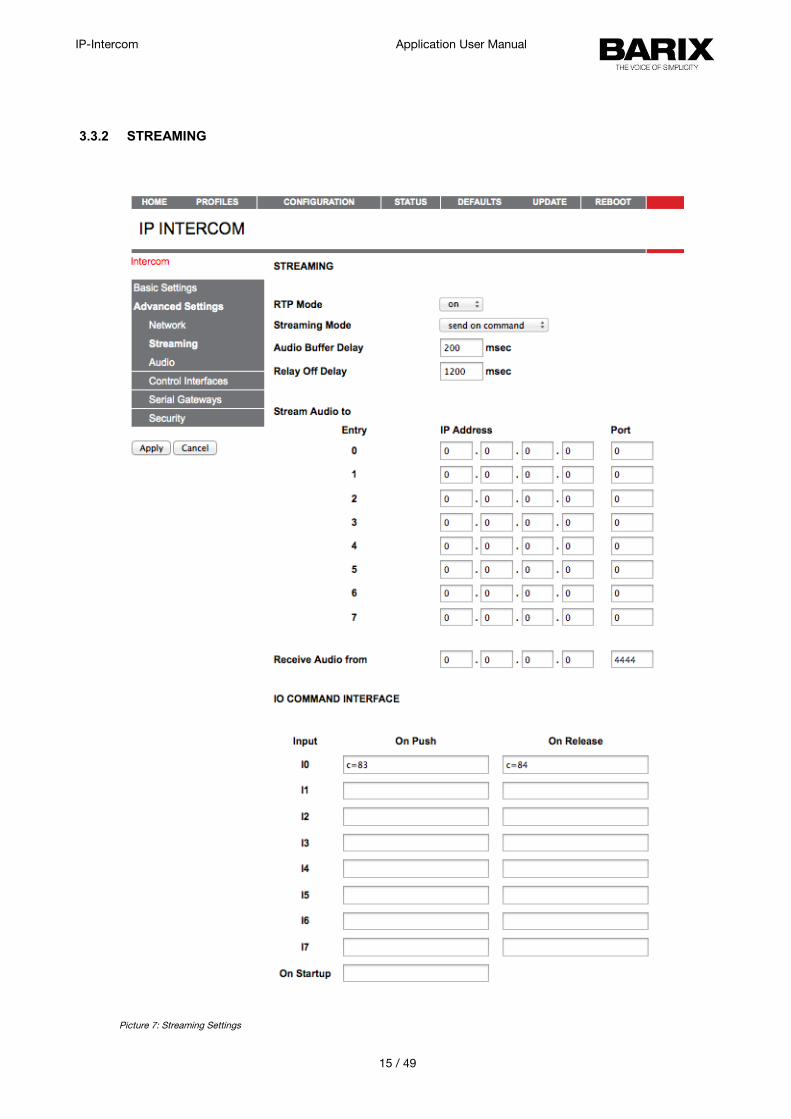
3.3.2 STREAMING
15 / 49
Picture 7: Streaming Settings
IP-Intercom Application User Manual
➢ RTP Mode Select audio streaming protocol. Select one of the following options.
1. "on":Audio will be transmitted over RTP (used in VoIP systems) .2. "off":Audio will be transmitted using raw UDP protocol.
Default: on
➢ Streaming ModeSelect audio streaming mode. Select one of the following options.
1. "send always" will stream always to configured destination. Entry 0 from “Stream Audio to” table is selected by default for streaming. Other entries from the table can be selected using command interface.
As the application is designed for intercom operations therefore only one streaming destination can activated at a time.
2. "send on command" will stream if it has received command to start streaming (c=83 ).
3. “send level” will start streaming audio if input audio level becomes above the threshold “Input Trigger Level” level.
4. “respond” will stream audio to the host from which it is receiving audio. the device will learn the destination ip and port from the incoming audio stream. The devices will stop streaming if it does not receive audio for “Inactivity Timeout” period.
Default: send on command.
➢ Stream Audio to Set the destination host IP and port where you want to stream the audio. DestinationIP could be unicast, multicast, broadcast address. It can be changed also over command interface . Set the port to 0 to disable the streaming.
Default: 0.0.0.0:4444
➢ Audio Buffer DelayThe RTP decoder keeps constant decoding latency within one frame accuracy.Set the required delay in milliseconds. The delay value should be set largeenough to cope with network jitter (difference in packets delivery time) andpossible packet loss. Increase the value if you are experiencing audio dropout.The lowest recommended setting is about 80ms for uLaw/ALaw 8kHz.
Default: 100 msec
➢ Relay Off DelaySet this to activate relay when there is incoming audio. If there is no audio for this configured interval, relay shall be opened. To disable it, set it to 0. Using this parameter, the output relay activation can be prolonged, which can be useful when the relay is being used to control, for example, an amplifier. The relay off delay is needed when using MP3 encoding, where the unpredictable nature of the compression means that it is not possible to predict how long the audio will take to reach and transmit at the remote end.
Default: 1200 msec
➢ Stream Audio to Use this table to configure a list of destinations. A destination from this table can be selected for streaming using SETTARGET command.
16 / 49
IP-Intercom Application User Manual
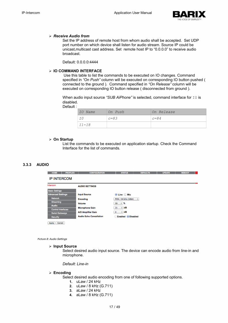
➢ Receive Audio from Set the IP address of remote host from whom audio shall be accepted. Set UDP port number on which device shall listen for audio stream. Source IP could be unicast,multicast cast address. Set remote host IP to “0.0.0.0” to receive audio broadcast.
Default: 0.0.0.0:4444
➢ IO COMMAND INTERFACE Use this table to list the commands to be executed on IO changes. Command specified in “On Push” column will be executed on corresponding IO button pushed (connected to the ground ). Command specified in “On Release” column will be executed on corresponding IO button release ( disconnected from ground ).
When audio input source “SUB AiPhone” is selected, command interface for I0 is disabled.Default :
IO Name On Push On Release
I0 c=83 c=84
I1-I8
➢ On StartupList the commands to be executed on application startup. Check the Command Interface for the list of commands.
3.3.3 AUDIO
➢ Input SourceSelect desired audio input source. The device can encode audio from line-in and microphone.
Default: Line-in
➢ EncodingSelect desired audio encoding from one of following supported options.
1. uLaw / 24 kHz 2. uLaw / 8 kHz (G.711)3. aLaw / 24 kHz4. aLaw / 8 kHz (G.711)
17 / 49
Picture 8: Audio Settings
IP-Intercom Application User Manual
5. PCM / 24 kHz (16bit)6. PCM / 8 kHz (16bit)
Default: PCM/24kHz(16 bit)
➢ VolumeSelect desired volume level. It also can be set at run time using command interface. Volume can be selected in 5% steps from 0 to 100%. Setting volume level 0 will mute the speaker.
Default : 50 %
➢ Microphone GainSelect desired microphone gain from 21 dB to 43.5dB in 1.5 dB steps. It can be set at run time also using command interface. This gain is not valid if audio input sourceline-in is selected.
Default: 21 dB
➢ A/D Amplifier GainA/D converter pre-amplification in dB. Increase if the audio signal too faint, decrease if it's too loud or overdriven. Select desired Amplifier gain from -3db to 19.5 dB in 1.5dB steps. It can be set at run time also using command interface.
Default: 0 dB
➢ Audio Echo Cancellation Enable or disable the AEC here. Enabling audio echo cancellation will reduce the echo and improves the voice quality. Echo cancellation can be enabled only with uLaw, aLaw, PCM 8kHz audio quality set and full duplex mode is used. The Application is always in the full duplex mode except when “SUB( AiPhone)” audio input source is set. This feature is only available on devices having IPAM 102, and IPAM 302.
Default: "disabled"
18 / 49
IP-Intercom Application User Manual
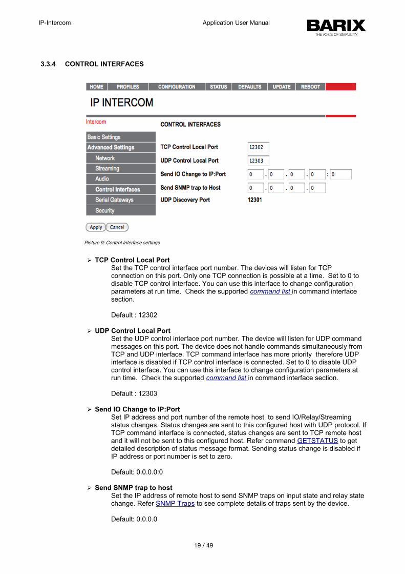
3.3.4 CONTROL INTERFACES
➢ TCP Control Local PortSet the TCP control interface port number. The devices will listen for TCP connection on this port. Only one TCP connection is possible at a time. Set to 0 to disable TCP control interface. You can use this interface to change configuration parameters at run time. Check the supported command list in command interface section.
Default : 12302
➢ UDP Control Local PortSet the UDP control interface port number. The device will listen for UDP command messages on this port. The device does not handle commands simultaneously from TCP and UDP interface. TCP command interface has more priority therefore UDP interface is disabled if TCP control interface is connected. Set to 0 to disable UDP control interface. You can use this interface to change configuration parameters at run time. Check the supported command list in command interface section.
Default : 12303
➢ Send IO Change to IP:PortSet IP address and port number of the remote host to send IO/Relay/Streaming status changes. Status changes are sent to this configured host with UDP protocol. IfTCP command interface is connected, status changes are sent to TCP remote host and it will not be sent to this configured host. Refer command GETSTATUS to get detailed description of status message format. Sending status change is disabled if IP address or port number is set to zero.
Default: 0.0.0.0:0
➢ Send SNMP trap to hostSet the IP address of remote host to send SNMP traps on input state and relay state change. Refer SNMP Traps to see complete details of traps sent by the device.
Default: 0.0.0.0
19 / 49
Picture 9: Control Interface settings
IP-Intercom Application User Manual
➢ UDP Discovery PortThe UDP port to discover devices running IP-intercom. This port is fixed to 12301 and is not configurable.
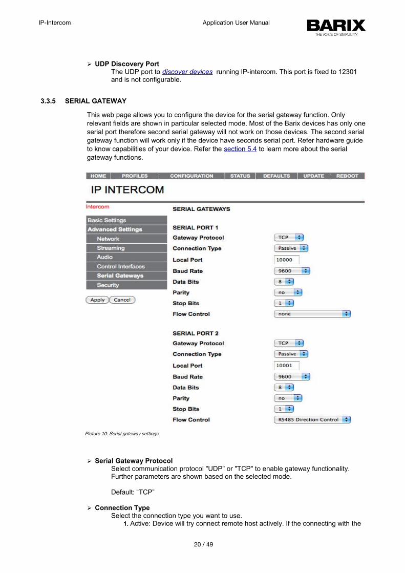
3.3.5 SERIAL GATEWAY
This web page allows you to configure the device for the serial gateway function. Only relevant fields are shown in particular selected mode. Most of the Barix devices has only oneserial port therefore second serial gateway will not work on those devices. The second serial gateway function will work only if the device have seconds serial port. Refer hardware guide to know capabilities of your device. Refer the section 5.4 to learn more about the serial gateway functions.
➢ Serial Gateway ProtocolSelect communication protocol "UDP" or "TCP" to enable gateway functionality.Further parameters are shown based on the selected mode.
Default: “TCP”
➢ Connection TypeSelect the connection type you want to use.
1. Active: Device will try connect remote host actively. If the connecting with the
20 / 49
Picture 10: Serial gateway settings
IP-Intercom Application User Manual
remote host fails, it will try to reconnect again in 10 seconds.2. Passive: Listen for incoming connection. Only one TCP connection is possible
at a time.NOTE: UDP Protocol does not support passive connection.
Default: “Passive”
➢ Local PortSet port number to listen for TCP passive connection. When connection type “active”selected, local port is selected at random.
Default: “10001”
➢ Remote HostSet IP address of remote host to establish TCP connection or to send UDP packet.
Default: “0.0.0.0”
➢ Remote PortSet TCP/UDP port number of the remote Host to establish active connection.
Default: “0.0.0.0”
➢ Baud RateSelect the serial transmission speed ("300" to "230400" Baud).
Default: "9600"
➢ Data BitsSelect "7" or "8" data bits.
Default: "8"
➢ ParitySelect "no", "even" or "odd" parity.
Default: "no"
➢ Stop BitsSelect "1" or "2" stop bits. When parity bit is used, 2 stop bit is not possible.
Default: "1"
➢ Flow ControlSelect the type of flow control: "none": RTS/CTS signals are not used. "Software flow control(XON/XOFF)" or "Hardware flow control (RTS/CTS)": When using RS-232 serial port."RS485 direction control": This must be set when using RS-485 serial port.
Default: "none".
21 / 49
IP-Intercom Application User Manual
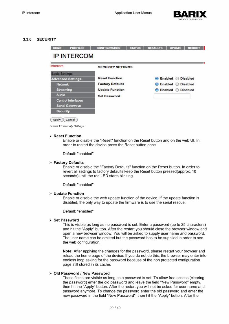
3.3.6 SECURITY
➢ Reset FunctionEnable or disable the "Reset" function on the Reset button and on the web UI. In order to restart the device press the Reset button once.
Default: "enabled"
➢ Factory DefaultsEnable or disable the "Factory Defaults" function on the Reset button. In order to revert all settings to factory defaults keep the Reset button pressed(approx. 10 seconds) until the red LED starts blinking.
Default: "enabled"
➢ Update FunctionEnable or disable the web update function of the device. If the update function is disabled, the only way to update the firmware is to use the serial rescue.
Default: "enabled"
➢ Set PasswordThis is visible as long as no password is set. Enter a password (up to 25 characters) and hit the "Apply" button. After the restart you should close the browser window andopen a new browser window. You will be asked to supply user name and password. The user name can be omitted but the password has to be supplied in order to see the web configuration.
Note: After applying the changes for the password, please restart your browser and reload the home page of the device. If you do not do this, the browser may enter intoendless loop asking for the password because of the non protected configuration page still stored in its cache.
➢ Old Password / New PasswordThese fields are visible as long as a password is set. To allow free access (clearing the password) enter the old password and leave the field "New Password" empty, then hit the "Apply" button. After the restart you will not be asked for user name and password anymore. To change the password enter the old password and enter the new password in the field "New Password", then hit the "Apply" button. After the
22 / 49
Picture 11: Security Settings
IP-Intercom Application User Manual
restart you will be asked for user name and password. The user name can be omitted but the new password has to be supplied in order to see the web configuration.
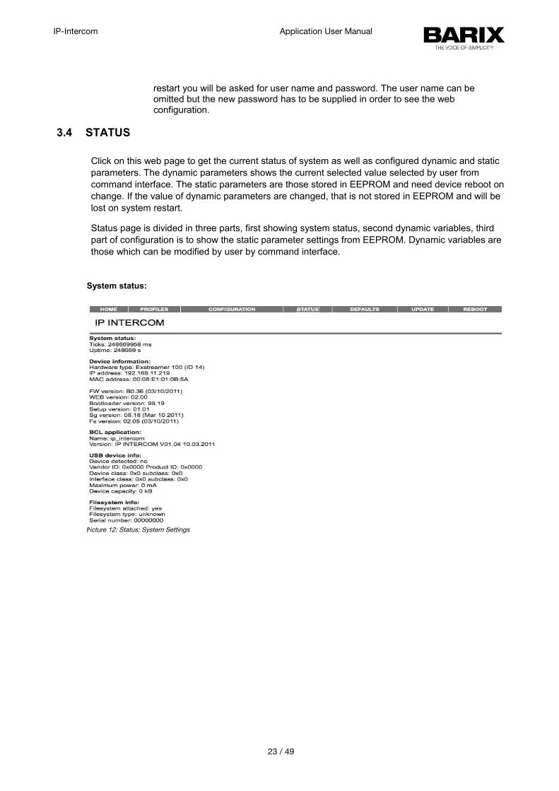
3.4 STATUS
Click on this web page to get the current status of system as well as configured dynamic and static parameters. The dynamic parameters shows the current selected value selected by user from command interface. The static parameters are those stored in EEPROM and need device reboot onchange. If the value of dynamic parameters are changed, that is not stored in EEPROM and will be lost on system restart.
Status page is divided in three parts, first showing system status, second dynamic variables, third part of configuration is to show the static parameter settings from EEPROM. Dynamic variables are those which can be modified by user by command interface.
System status:
23 / 49
Picture 12: Status: System Settings

IP-Intercom Application User Manual
Dynamic parameters:
Picture 13: Status: Dynamic Settings
24 / 49
IP-Intercom Application User Manual
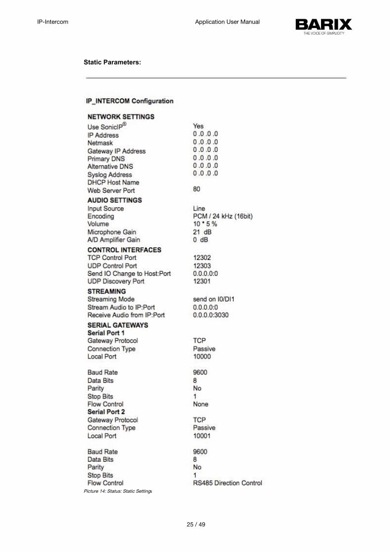
Static Parameters:
25 / 49
Picture 14: Status: Static Settings
IP-Intercom Application User Manual
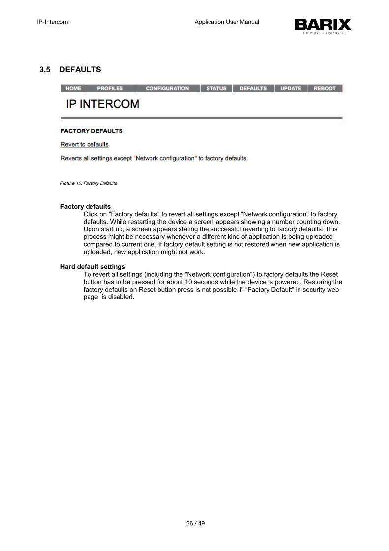
3.5 DEFAULTS
Factory defaultsClick on "Factory defaults" to revert all settings except "Network configuration" to factory defaults. While restarting the device a screen appears showing a number counting down. Upon start up, a screen appears stating the successful reverting to factory defaults. This process might be necessary whenever a different kind of application is being uploaded compared to current one. If factory default setting is not restored when new application is uploaded, new application might not work.
Hard default settingsTo revert all settings (including the "Network configuration") to factory defaults the Reset button has to be pressed for about 10 seconds while the device is powered. Restoring the factory defaults on Reset button press is not possible if “Factory Default” in security web page is disabled.
26 / 49
Picture 15: Factory Defaults
IP-Intercom Application User Manual
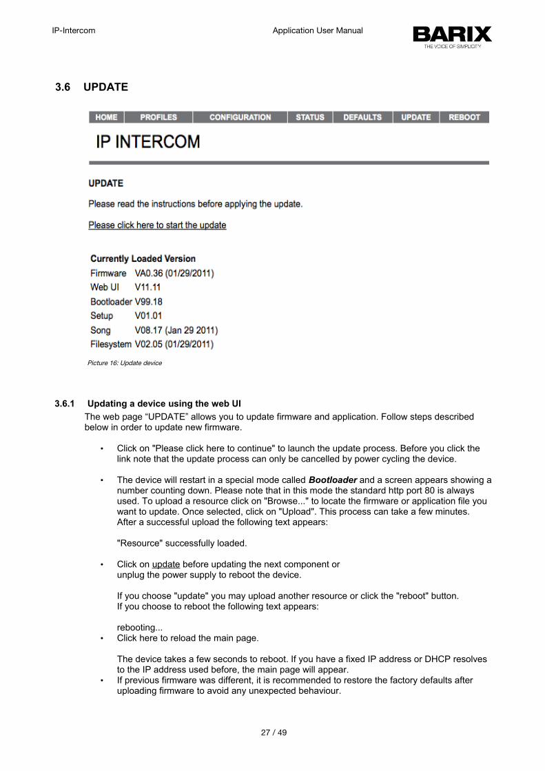
3.6 UPDATE
3.6.1 Updating a device using the web UI
The web page “UPDATE” allows you to update firmware and application. Follow steps described below in order to update new firmware.
• Click on "Please click here to continue" to launch the update process. Before you click the link note that the update process can only be cancelled by power cycling the device.
• The device will restart in a special mode called Bootloader and a screen appears showing anumber counting down. Please note that in this mode the standard http port 80 is always used. To upload a resource click on "Browse..." to locate the firmware or application file you want to update. Once selected, click on "Upload". This process can take a few minutes. After a successful upload the following text appears:
"Resource" successfully loaded.
• Click on update before updating the next component or unplug the power supply to reboot the device.
If you choose "update" you may upload another resource or click the "reboot" button.If you choose to reboot the following text appears:
rebooting...• Click here to reload the main page.
The device takes a few seconds to reboot. If you have a fixed IP address or DHCP resolves to the IP address used before, the main page will appear.
• If previous firmware was different, it is recommended to restore the factory defaults after uploading firmware to avoid any unexpected behaviour.
27 / 49
Picture 16: Update device
IP-Intercom Application User Manual
Current Version of firmwares and application.
It also displays the current version of firmware.
Field Parameters
MAC MAC address of the device.
Firmware Current version of the Firmware.
Bootloader Current version of the Bootloader.
Song Current versions of the 2 FW extension modules.
File System Current version of file system extension module.
3.6.2 Updating the device using the RS-232 serial port
Sometimes when the device is not accessible via the LAN, or the image in the flash memory is corrupted for some reason, then a serial rescue may be needed to reset the device to the factory defaults1.
So, here are the steps that need to be executed to do the serial rescue:
• Disconnect the device from the power supply;
• Connect the COM port of the device to the COM port of your computer via a null modem serial cable;
• Open a terminal in the update_rescue directory in your unzipped copy of the ABCL SIP firmware,when using Linux or Mac, switch to update_rescue/linux_mac directory;
• On Windows systems start the rescue process by executing serialX.bat, where X is the number (1-4) of the serial port on the computer;
• If running on Linux /Mac execute the seriald.sh script, giving the device name of your COM port as a parameter. For example ./seriald.sh /dev/tty.UC-232AC
• Power on the device, and wait for the update to finish. The device will reboot automatically.
NOTE: All other settings except the network settings will be lost !
1 Rescuing the IP-Intercom using the serial port is more complex, and requires some engineering work. Please contact BARIX Support to get more information.
28 / 49
IP-Intercom Application User Manual
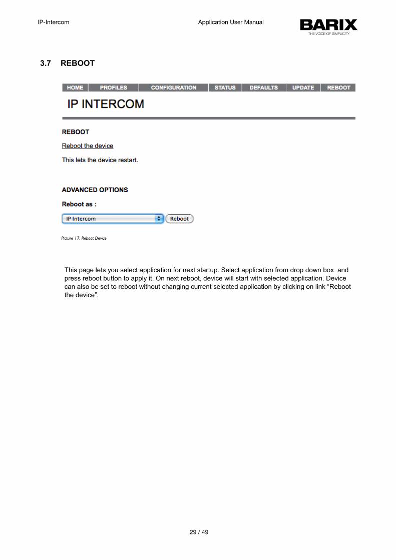
3.7 REBOOT
This page lets you select application for next startup. Select application from drop down box and press reboot button to apply it. On next reboot, device will start with selected application. Device can also be set to reboot without changing current selected application by clicking on link “Reboot the device”.
29 / 49
Picture 17: Reboot Device
IP-Intercom Application User Manual
4 Configuration Parameters
4.1 EEPROM setup parameters and default values
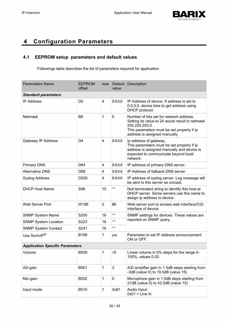
Followings table describes the list of parameters required for application.
Parameters Name EEPROM offset
size Defaultvalue
Description
Standard parameters
IP Address D0 4 0.0.0.0 IP Address of device. If address is set to 0.0.0.0, device tries to get address using DHCP protocol.
Netmask B8 1 0 Number of bits set for network address. Setting its value to 24 would result in netmask255.255.255.0.This parameters must be set properly if ip address is assigned manually.
Gateway IP Address D4 4 0.0.0.0 Ip address of gateway. This parameters must be set properly if ip address is assigned manually and device is expected to communicate beyond local network.
Primary DNS D64 4 0.0.0.0 IP address of primary DNS server.
Alternative DNS D68 4 0.0.0.0 IP Address of fallback DNS server.
Syslog Address D200 4 0.0.0.0 IP address of syslog server. Log message willbe sent to this server as unicast.
DHCP Host Name S98 15 “” Null terminated string to identify this host at DHCP server. Some servers use this name toassign ip address to device.
Web Server Port W196 2 80 Web server port to access web interface/CGI interface of device.
SNMP System Name S205 16 “” SNMP settings for devices. These values are reported on SNMP query.
SNMP System Location S223 16 “”
SNMP System Contact S241 16 “”
Use SonicIP® B198 1 yes Parameter to set IP address announcement ON or OFF.
Application Specific Parameters
Volume B500 1 10 Linear volume in 5% steps for the range 0-100%, values 0-20
AD-gain B501 1 2 A/D amplifier gain in 1.5dB steps starting from-3dB (value 0) to 19.5dB (value 15)
Mic-gain B502 1 0 Microphone gain in 1.5dB steps starting from 21dB (value 0) to 43.5dB (value 15)
Input mode B510 1 0x81 Audio Input:0x01 = Line In
30 / 49
IP-Intercom Application User Manual
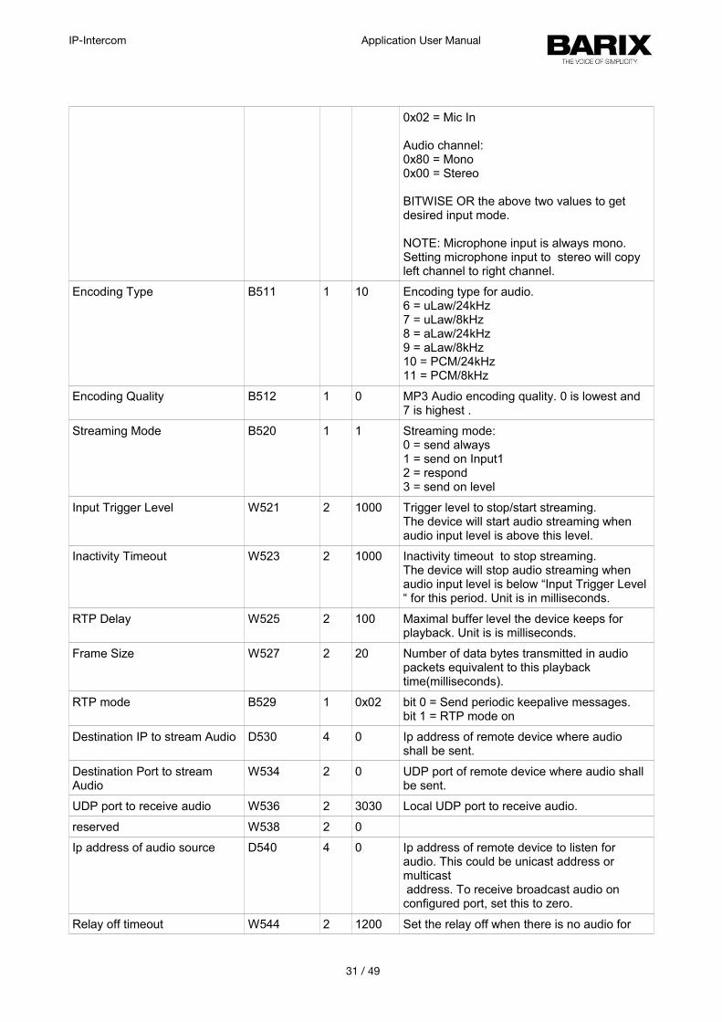
0x02 = Mic In
Audio channel:0x80 = Mono0x00 = Stereo
BITWISE OR the above two values to get desired input mode.
NOTE: Microphone input is always mono. Setting microphone input to stereo will copy left channel to right channel.
Encoding Type B511 1 10 Encoding type for audio.6 = uLaw/24kHz7 = uLaw/8kHz8 = aLaw/24kHz9 = aLaw/8kHz10 = PCM/24kHz11 = PCM/8kHz
Encoding Quality B512 1 0 MP3 Audio encoding quality. 0 is lowest and 7 is highest .
Streaming Mode B520 1 1 Streaming mode:0 = send always1 = send on Input12 = respond3 = send on level
Input Trigger Level W521 2 1000 Trigger level to stop/start streaming.The device will start audio streaming when audio input level is above this level.
Inactivity Timeout W523 2 1000 Inactivity timeout to stop streaming.The device will stop audio streaming when audio input level is below “Input Trigger Level “ for this period. Unit is in milliseconds.
RTP Delay W525 2 100 Maximal buffer level the device keeps for playback. Unit is is milliseconds.
Frame Size W527 2 20 Number of data bytes transmitted in audio packets equivalent to this playback time(milliseconds).
RTP mode B529 1 0x02 bit 0 = Send periodic keepalive messages.bit 1 = RTP mode on
Destination IP to stream Audio D530 4 0 Ip address of remote device where audio shall be sent.
Destination Port to stream Audio
W534 2 0 UDP port of remote device where audio shall be sent.
UDP port to receive audio W536 2 3030 Local UDP port to receive audio.
reserved W538 2 0
Ip address of audio source D540 4 0 Ip address of remote device to listen for audio. This could be unicast address or multicast address. To receive broadcast audio on configured port, set this to zero.
Relay off timeout W544 2 1200 Set the relay off when there is no audio for
31 / 49
IP-Intercom Application User Manual
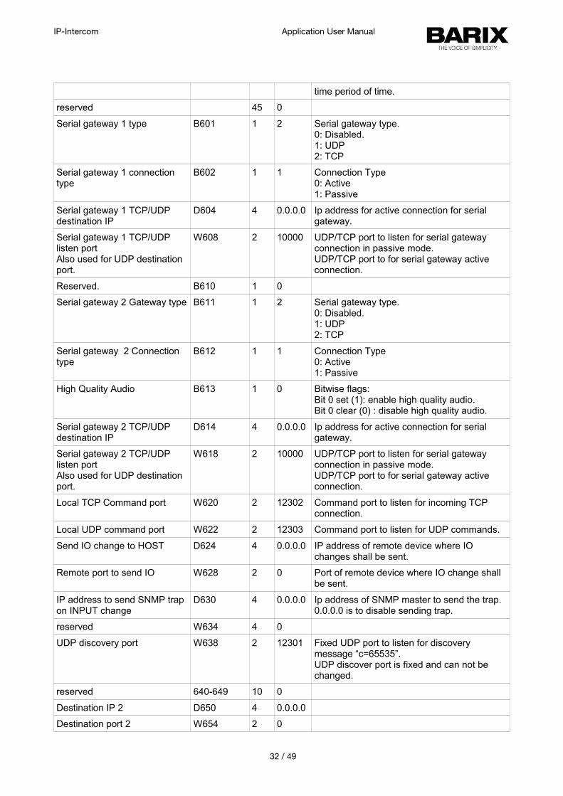
time period of time.
reserved 45 0
Serial gateway 1 type B601 1 2 Serial gateway type. 0: Disabled.1: UDP2: TCP
Serial gateway 1 connection type
B602 1 1 Connection Type0: Active1: Passive
Serial gateway 1 TCP/UDP destination IP
D604 4 0.0.0.0 Ip address for active connection for serial gateway.
Serial gateway 1 TCP/UDP listen portAlso used for UDP destination port.
W608 2 10000 UDP/TCP port to listen for serial gateway connection in passive mode.UDP/TCP port to for serial gateway active connection.
Reserved. B610 1 0
Serial gateway 2 Gateway type B611 1 2 Serial gateway type. 0: Disabled.1: UDP2: TCP
Serial gateway 2 Connection type
B612 1 1 Connection Type0: Active1: Passive
High Quality Audio B613 1 0 Bitwise flags:Bit 0 set (1): enable high quality audio.Bit 0 clear (0) : disable high quality audio.
Serial gateway 2 TCP/UDP destination IP
D614 4 0.0.0.0 Ip address for active connection for serial gateway.
Serial gateway 2 TCP/UDP listen portAlso used for UDP destination port.
W618 2 10000 UDP/TCP port to listen for serial gateway connection in passive mode.UDP/TCP port to for serial gateway active connection.
Local TCP Command port W620 2 12302 Command port to listen for incoming TCP connection.
Local UDP command port W622 2 12303 Command port to listen for UDP commands.
Send IO change to HOST D624 4 0.0.0.0 IP address of remote device where IO changes shall be sent.
Remote port to send IO W628 2 0 Port of remote device where IO change shall be sent.
IP address to send SNMP trap on INPUT change
D630 4 0.0.0.0 Ip address of SNMP master to send the trap. 0.0.0.0 is to disable sending trap.
reserved W634 4 0
UDP discovery port W638 2 12301 Fixed UDP port to listen for discovery message “c=65535”. UDP discover port is fixed and can not be changed.
reserved 640-649 10 0
Destination IP 2 D650 4 0.0.0.0
Destination port 2 W654 2 0
32 / 49
IP-Intercom Application User Manual
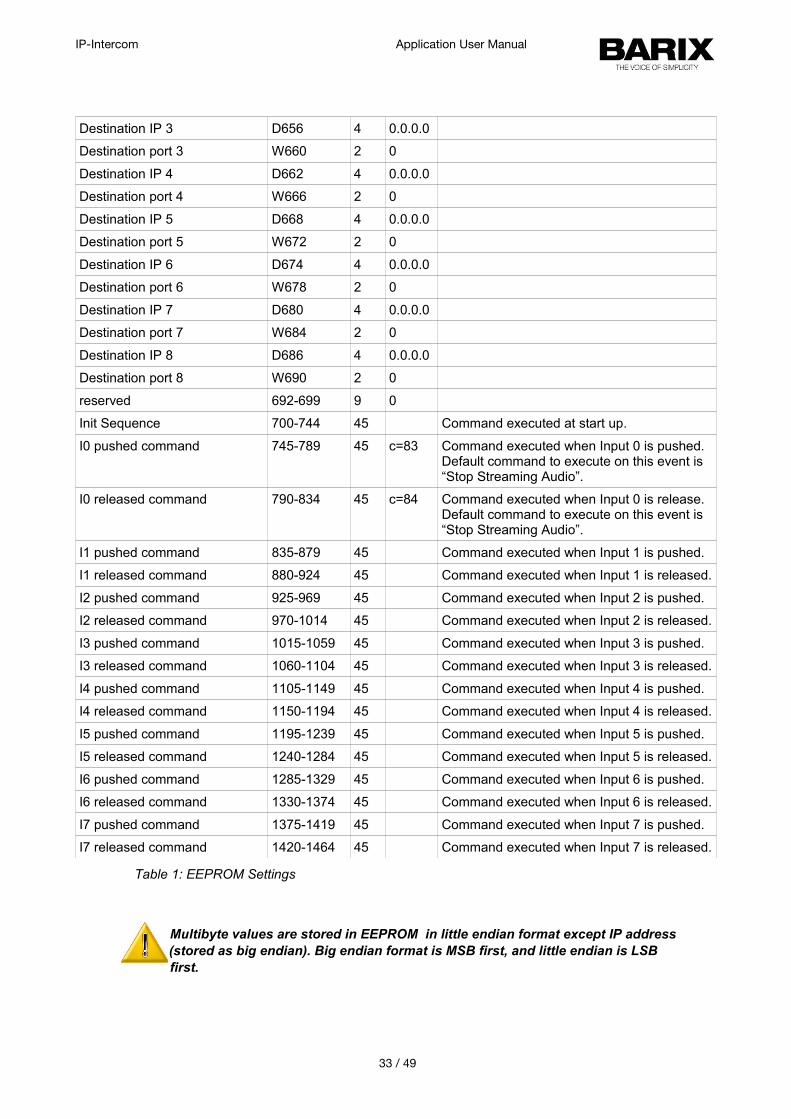
Destination IP 3 D656 4 0.0.0.0
Destination port 3 W660 2 0
Destination IP 4 D662 4 0.0.0.0
Destination port 4 W666 2 0
Destination IP 5 D668 4 0.0.0.0
Destination port 5 W672 2 0
Destination IP 6 D674 4 0.0.0.0
Destination port 6 W678 2 0
Destination IP 7 D680 4 0.0.0.0
Destination port 7 W684 2 0
Destination IP 8 D686 4 0.0.0.0
Destination port 8 W690 2 0
reserved 692-699 9 0
Init Sequence 700-744 45 Command executed at start up.
I0 pushed command 745-789 45 c=83 Command executed when Input 0 is pushed.Default command to execute on this event is “Stop Streaming Audio”.
I0 released command 790-834 45 c=84 Command executed when Input 0 is release. Default command to execute on this event is “Stop Streaming Audio”.
I1 pushed command 835-879 45 Command executed when Input 1 is pushed.
I1 released command 880-924 45 Command executed when Input 1 is released.
I2 pushed command 925-969 45 Command executed when Input 2 is pushed.
I2 released command 970-1014 45 Command executed when Input 2 is released.
I3 pushed command 1015-1059 45 Command executed when Input 3 is pushed.
I3 released command 1060-1104 45 Command executed when Input 3 is released.
I4 pushed command 1105-1149 45 Command executed when Input 4 is pushed.
I4 released command 1150-1194 45 Command executed when Input 4 is released.
I5 pushed command 1195-1239 45 Command executed when Input 5 is pushed.
I5 released command 1240-1284 45 Command executed when Input 5 is released.
I6 pushed command 1285-1329 45 Command executed when Input 6 is pushed.
I6 released command 1330-1374 45 Command executed when Input 6 is released.
I7 pushed command 1375-1419 45 Command executed when Input 7 is pushed.
I7 released command 1420-1464 45 Command executed when Input 7 is released.
Table 1: EEPROM Settings
Multibyte values are stored in EEPROM in little endian format except IP address (stored as big endian). Big endian format is MSB first, and little endian is LSB first.
33 / 49
IP-Intercom Application User Manual
5 Advanced Use of the IP-intercom
5.1 Command Interface
The IP-intercom is implementing a command interface to accept any command from the master. On reception of the command from the remote panel, the device takes the corresponding action. Sections below are describing the communication protocol and its limitations.
5.1.1 Command interface Protocol
1. Request commands and responses are printable text based. Non printable characters in command is not allowed.
2. Every command must be terminated by carriage ( CR - “\r” hex 0x0d ) return or line feed ( LF - “\n”, hex 0x0a ) or comma “,” ( hex 0x2C ) or null ( hex 0x00 )
3. Parameters of commands are separated by “&”.4. All commands and parameter names are case sensitive.5. The device sends a “nack” message if the requested command is not supported or
parameters of the command are not correct.6. Some commands do not send back a response as a result of their execution. For
example, setting the volume with command “l=15” does not return any result. In this case the device sends an “ack” reply as a feedback that the command is successfully executed.
7. The device shall not reply “ack” if there is a response message generated as result of the command execution. i.e. command “q=all” returns the state of all I/Os.
8. The command interface supports TCP and UDP protocol that can be active simultaneously. The reply is sent back to the originating interface.
9. The default TCP command port is 12302 and the default UDP command port is 12303. The command interface will be disabled if the corresponding port is set to 0.
10. TCP command connection has priority. If TCP connection is active ( connected ), status changes shall be sent to it only.
11. IO and Relay count are counted from 0 to max - 1. Where “max” is the number of IO or relays available on the hardware being used.
34 / 49
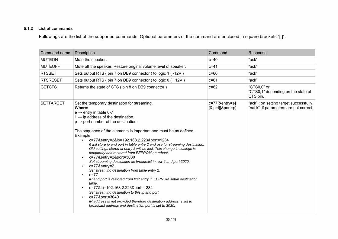
5.1.2 List of commands
Followings are the list of the supported commands. Optional parameters of the command are enclosed in square brackets “[ ]”.
Command name Description Command Response
MUTEON Mute the speaker. c=40 “ack”
MUTEOFF Mute off the speaker. Restore original volume level of speaker. c=41 “ack”
RTSSET Sets output RTS ( pin 7 on DB9 connector ) to logic 1 ( -12V ) c=60 “ack”
RTSRESET Sets output RTS ( pin 7 on DB9 connector ) to logic 0 ( +12V ) c=61 “ack”
GETCTS Returns the state of CTS ( pin 8 on DB9 connector ) c=62 “CTS0,0” or“CTS0,1” depending on the state of CTS pin.
SETTARGET Set the temporary destination for streaming.Where:e → entry in table 0-7i → ip address of the destination.p → port number of the destination. The sequence of the elements is important and must be as defined.Example:
• c=77&entry=2&ip=192.168.2.223&port=1234it will store ip and port in table entry 2 and use for streaming destination. Old settings stored at entry 2 will be lost. This change in settings is temporary and restored from EEPROM on reboot.
• c=77&entry=2&port=3030Set streaming destination as broadcast in row 2 and port 3030.
• c=77&entry=2Set streaming destination from table entry 2.
• c=77IP and port is restored from first entry in EEPROM setup destination table.
• c=77&ip=192.168.2.223&port=1234Set streaming destination to this ip and port.
• c=77&port=3040IP address is not provided therefore destination address is set to broadcast address and destination port is set to 3030.
c=77[&entry=e][&ip=i][&port=p]
“ack” : on setting target successfully.“nack”: if parameters are not correct.
35 / 49
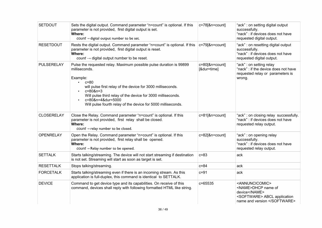
SETDOUT Sets the digital output. Command parameter “n=count” is optional. If this parameter is not provided, first digital output is set.Where: count digital output number to be set. →
c=78[&n=count] “ack” : on setting digital output successfully.“nack” : if devices does not have requested digital output.
RESETDOUT Rests the digital output. Command parameter “n=count” is optional. If this parameter is not provided, first digital output is reset.Where: count → digital output number to be reset.
c=79[&n=count] “ack” : on resetting digital output successfully.“nack” : if devices does not have requested digital output.
PULSERELAY Pulse the requested relay. Maximum possible pulse duration is 99899 milliseconds.
Example:• c=80
will pulse first relay of the device for 3000 milliseconds.• c=80&n=3
Will pulse third relay of the device for 3000 milliseconds.• c=80&n=4&dur=5000
Will pulse fourth relay of the device for 5000 milliseconds.
c=80[&n=count][&dur=time]
“ack” : on setting relay“nack” : if the device does not have requested relay or parameters is wrong.
CLOSERELAY Close the Relay. Command parameter “n=count” is optional. If this parameter is not provided, first relay shall be closed.Where: count relay number to be closed.→
c=81[&n=count] “ack” : on closing relay successfully.“nack” : if devices does not have requested relay output.
OPENRELAY Open the Relay. Command parameter “n=count” is optional. If this parameter is not provided, first relay shall be opened.Where: count Relay number to be opened.→
c=82[&n=count] “ack” : on opening relay successfully.“nack” : if devices does not have requested relay output.
SETTALK Starts talking/streaming. The device will not start streaming if destination is not set. Streaming will start as soon as target is set.
c=83 ack
RESETTALK Stops talking/streaming. c=84 ack
FORCETALK Starts talking/streaming even if there is an incoming stream. As this application is full-duplex, this command is identical to SETTALK.
c=91 ack
DEVICE Command to get device type and its capabilities. On receive of this command, devices shall reply with following formatted HTML like string.
c=65535 <ANNUNCICOMIC><NAME>DHCP name of device</NAME> <SOFTWARE> ABCL application name and version </SOFTWARE>
36 / 49
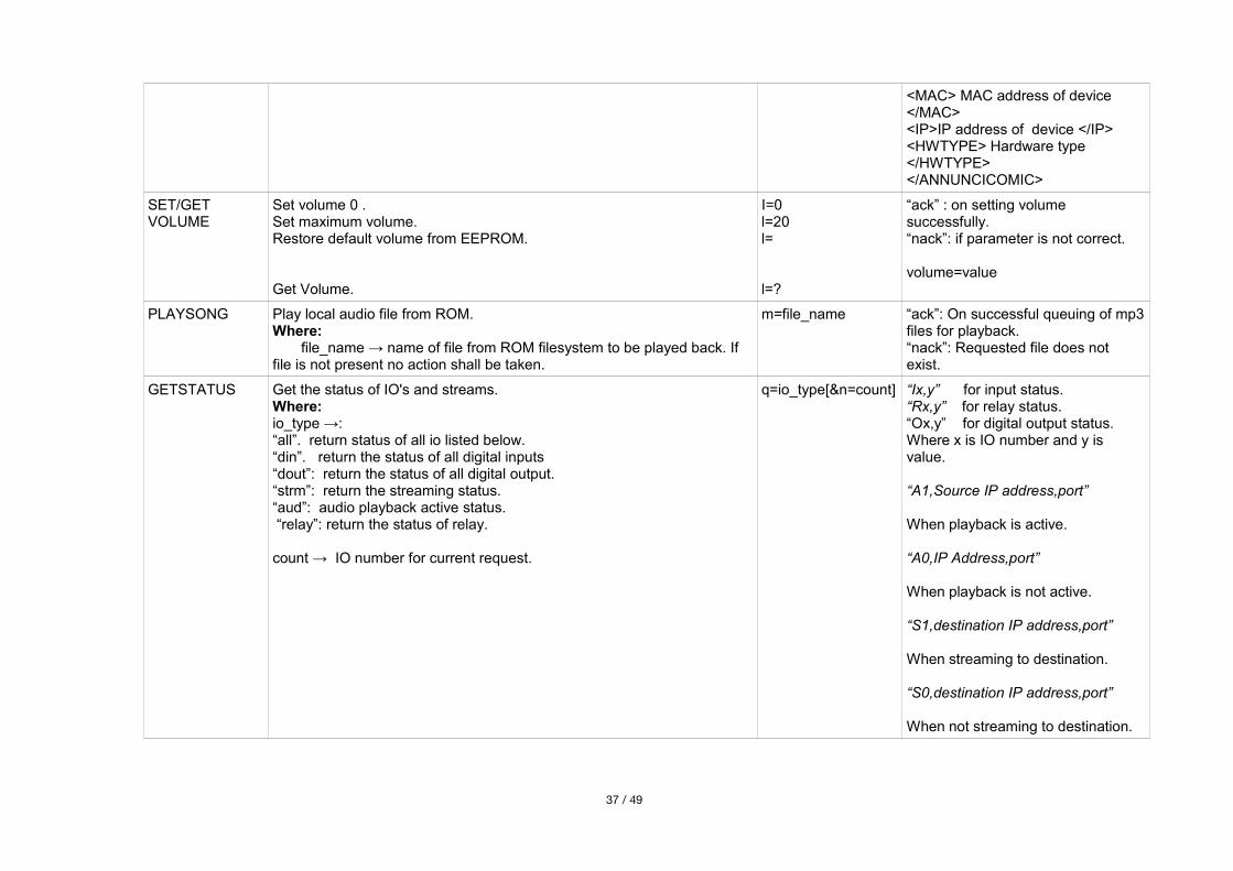
<MAC> MAC address of device </MAC><IP>IP address of device </IP><HWTYPE> Hardware type </HWTYPE></ANNUNCICOMIC>
SET/GET VOLUME
Set volume 0 .Set maximum volume.Restore default volume from EEPROM.
Get Volume.
I=0l=20l=
l=?
“ack” : on setting volume successfully.“nack”: if parameter is not correct.
volume=value
PLAYSONG Play local audio file from ROM.Where: file_name → name of file from ROM filesystem to be played back. If file is not present no action shall be taken.
m=file_name “ack”: On successful queuing of mp3files for playback.“nack”: Requested file does not exist.
GETSTATUS Get the status of IO's and streams. Where:io_type →: “all”. return status of all io listed below.“din”. return the status of all digital inputs“dout”: return the status of all digital output.“strm”: return the streaming status.“aud”: audio playback active status. “relay”: return the status of relay.
count → IO number for current request.
q=io_type[&n=count] “Ix,y” for input status.“Rx,y” for relay status.“Ox,y” for digital output status.Where x is IO number and y is value.
“A1,Source IP address,port”
When playback is active.
“A0,IP Address,port”
When playback is not active.
“S1,destination IP address,port”
When streaming to destination.
“S0,destination IP address,port”
When not streaming to destination.
37 / 49
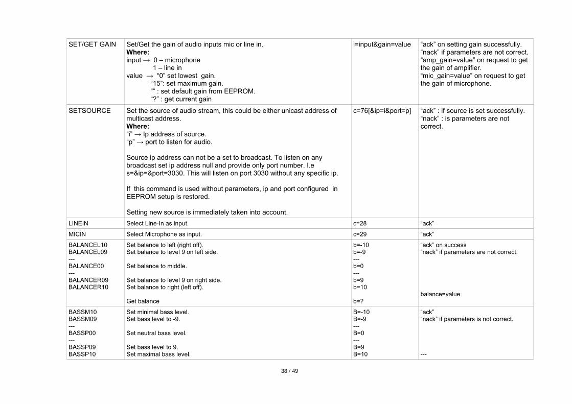
SET/GET GAIN Set/Get the gain of audio inputs mic or line in.Where:input → 0 – microphone 1 – line invalue → “0” set lowest gain.
“15”: set maximum gain.“” : set default gain from EEPROM.“?” : get current gain
i=input&gain=value “ack” on setting gain successfully.“nack” if parameters are not correct.“amp_gain=value” on request to get the gain of amplifier.“mic_gain=value” on request to get the gain of microphone.
SETSOURCE Set the source of audio stream, this could be either unicast address of multicast address.Where:“i” → Ip address of source. “p” → port to listen for audio.
Source ip address can not be a set to broadcast. To listen on any broadcast set ip address null and provide only port number. I.e s=&ip=&port=3030. This will listen on port 3030 without any specific ip.
If this command is used without parameters, ip and port configured in EEPROM setup is restored.
Setting new source is immediately taken into account.
c=76[&ip=i&port=p] “ack” : if source is set successfully.“nack” : is parameters are not correct.
LINEIN Select Line-In as input. c=28 “ack”
MICIN Select Microphone as input. c=29 “ack”
BALANCEL10BALANCEL09---BALANCE00---BALANCER09BALANCER10
Set balance to left (right off).Set balance to level 9 on left side.
Set balance to middle.
Set balance to level 9 on right side.Set balance to right (left off).
Get balance
b=-10b=-9---b=0---b=9b=10
b=?
“ack” on success“nack” if parameters are not correct.
balance=value
BASSM10BASSM09---BASSP00---BASSP09BASSP10
Set minimal bass level.Set bass level to -9.
Set neutral bass level.
Set bass level to 9.Set maximal bass level.
B=-10B=-9---B=0---B=9B=10
“ack”“nack” if parameters is not correct.
---
38 / 49
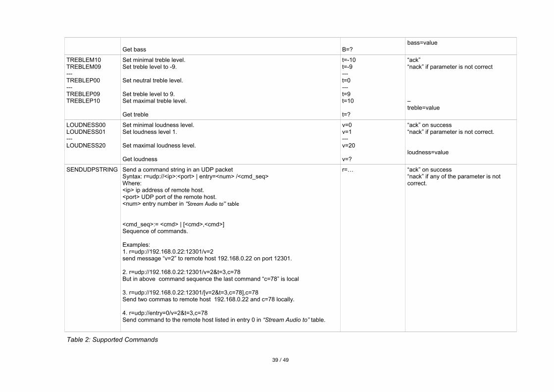
Get bass B=?bass=value
TREBLEM10TREBLEM09---TREBLEP00---TREBLEP09TREBLEP10
Set minimal treble level.Set treble level to -9.
Set neutral treble level.
Set treble level to 9.Set maximal treble level.
Get treble
t=-10t=-9---t=0---t=9t=10
t=?
“ack”“nack” if parameter is not correct
–treble=value
LOUDNESS00LOUDNESS01---LOUDNESS20
Set minimal loudness level.Set loudness level 1.
Set maximal loudness level.
Get loudness
v=0v=1---v=20
v=?
“ack” on success“nack” if parameter is not correct.
loudness=value
SENDUDPSTRING Send a command string in an UDP packetSyntax: r=udp://<ip>:<port> | entry=<num> /<cmd_seq>Where:<ip> ip address of remote host.<port> UDP port of the remote host.<num> entry number in “Stream Audio to” table
<cmd_seq>:= <cmd> | [<cmd>,<cmd>]Sequence of commands.
Examples: 1. r=udp://192.168.0.22:12301/v=2 send message “v=2” to remote host 192.168.0.22 on port 12301.
2. r=udp://192.168.0.22:12301/v=2&t=3,c=78 But in above command sequence the last command “c=78” is local
3. r=udp://192.168.0.22:12301/[v=2&t=3,c=78],c=78Send two commas to remote host 192.168.0.22 and c=78 locally.
4. r=udp://entry=0/v=2&t=3,c=78Send command to the remote host listed in entry 0 in “Stream Audio to” table.
r=… “ack” on success“nack” if any of the parameter is not correct.
Table 2: Supported Commands
39 / 49
5.2 Discovering Devices
The IP-Intercom listens for discovery command “c=65535” on fixed UDP port 12301. This command is also supported on the TCP/UDP command interfaces but the reply message is formatted differently. Any standard tool like netcat can be used from Linux/Mac PC terminal to send query message or you can develop own application to use this command and discover devices. On the reception of discover message, device sends two replies as below:
1. ANNBAR,IP address of device,MAC address of device,device type,ABCL application name and version,DHCP name of device\r
2. <ANNUNCICOMIC><NAME>DHCP name of device</NAME> <SOFTWARE>ABCL applicationname and version</SOFTWARE><MAC>MAC address of device</MAC><IP>IP address of device </IP><HWTYPE>Hardware type</HWTYPE></ANNUNCICOMIC>\r
In above messages “\r” (in hex 0x0D ) is carriage return.
5.3 CGI WEB interface
The Web interface can be accessed using any web browser. Using web interface, system parameters as well as application parameter can be modified. Web interface also can be accessed from any tools like netcat/wget/curl or from your own application on “Web Server Port” using HTTP method GET. You can read http://www.w3.org/Protocols/rfc2616/rfc2616-sec9.html to get more details about HTTP protocol GET method. The data sent to the web server must comply with HTTP 1.1 protocol.
Following is the list of CGI interfaces:
Interface name Description
setup.cgi - WEB Interface to update Configuration parameters stored in EEPROM.
BAS.cgi - WEB Interface to update BCL application's variables.
rc.cgi - WEB interface to execute command by firmware.
Table 3: CGI WEB Interfaces
For Example:
after making TCP connection from any application to device 192.168.40.43 and sending following message will reboot the device.
“GET /rc.cgi?c=99 HTTP/1.1\r\nHost: 192.168.40.43\r\nConnection: keep-alive\r\n\r\n”
in above example, “\r” is carriage return ( ASCII hex code 0x0d ) and “\n” is line feed ( ASCII hex code0x0a ).
5.3.1 rc.cgi
Following is the list of supported commands by rc.cgi interface.
40 / 49
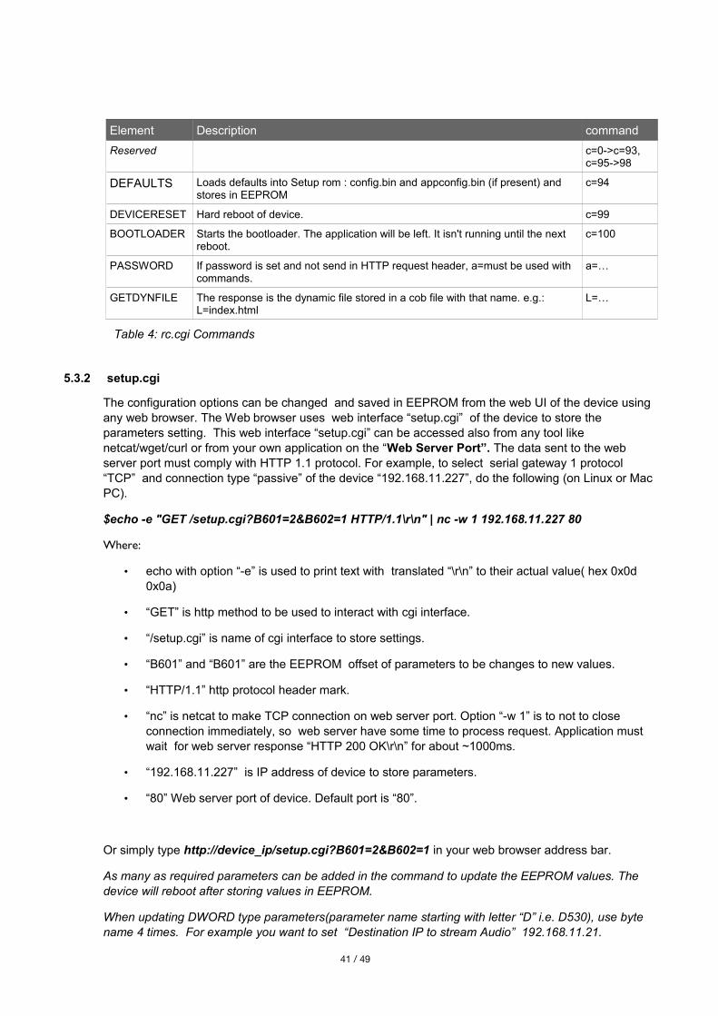
Element Description command
Reserved c=0->c=93, c=95->98
DEFAULTS Loads defaults into Setup rom : config.bin and appconfig.bin (if present) and stores in EEPROM
c=94
DEVICERESET Hard reboot of device. c=99
BOOTLOADER Starts the bootloader. The application will be left. It isn't running until the next reboot.
c=100
PASSWORD If password is set and not send in HTTP request header, a=must be used with commands.
a=…
GETDYNFILE The response is the dynamic file stored in a cob file with that name. e.g.: L=index.html
L=…
Table 4: rc.cgi Commands
5.3.2 setup.cgi
The configuration options can be changed and saved in EEPROM from the web UI of the device using any web browser. The Web browser uses web interface “setup.cgi” of the device to store the parameters setting. This web interface “setup.cgi” can be accessed also from any tool like netcat/wget/curl or from your own application on the “Web Server Port”. The data sent to the web server port must comply with HTTP 1.1 protocol. For example, to select serial gateway 1 protocol “TCP” and connection type “passive” of the device “192.168.11.227”, do the following (on Linux or Mac PC).
$echo -e "GET /setup.cgi?B601=2&B602=1 HTTP/1.1\r\n" | nc -w 1 192.168.11.227 80
Where:
• echo with option “-e” is used to print text with translated “\r\n” to their actual value( hex 0x0d 0x0a)
• “GET” is http method to be used to interact with cgi interface.
• “/setup.cgi” is name of cgi interface to store settings.
• “B601” and “B601” are the EEPROM offset of parameters to be changes to new values.
• “HTTP/1.1” http protocol header mark.
• “nc” is netcat to make TCP connection on web server port. Option “-w 1” is to not to close connection immediately, so web server have some time to process request. Application must wait for web server response “HTTP 200 OK\r\n” for about ~1000ms.
• “192.168.11.227” is IP address of device to store parameters.
• “80” Web server port of device. Default port is “80”.
Or simply type http://device_ip/setup.cgi?B601=2&B602=1 in your web browser address bar.
As many as required parameters can be added in the command to update the EEPROM values. The device will reboot after storing values in EEPROM.
When updating DWORD type parameters(parameter name starting with letter “D” i.e. D530), use byte name 4 times. For example you want to set “Destination IP to stream Audio” 192.168.11.21.
41 / 49
parameter name is D530, use B530,B531,B532,B533. Here prefix “B” is to save value in 1 byte, therefore need 4 times to store DWORD address. See the example below how to store DWORD value in EEPROM in little endian sequence(MSB first).
$echo -e "GET /setup.cgi?B530=192&B531=168&B532=11&B533=21 HTTP/1.1\r\n" | nc -w 1 192.168.11.227 80
All multibyte values in EEPROM are saved in little endian format except IP addresses (stored as big endian, MSB first).
Use setup.cgi interface from script or from any other tool with caution, If settings are messed up, device may not be reachable and can malfunction.
5.3.3 BAS.cgi
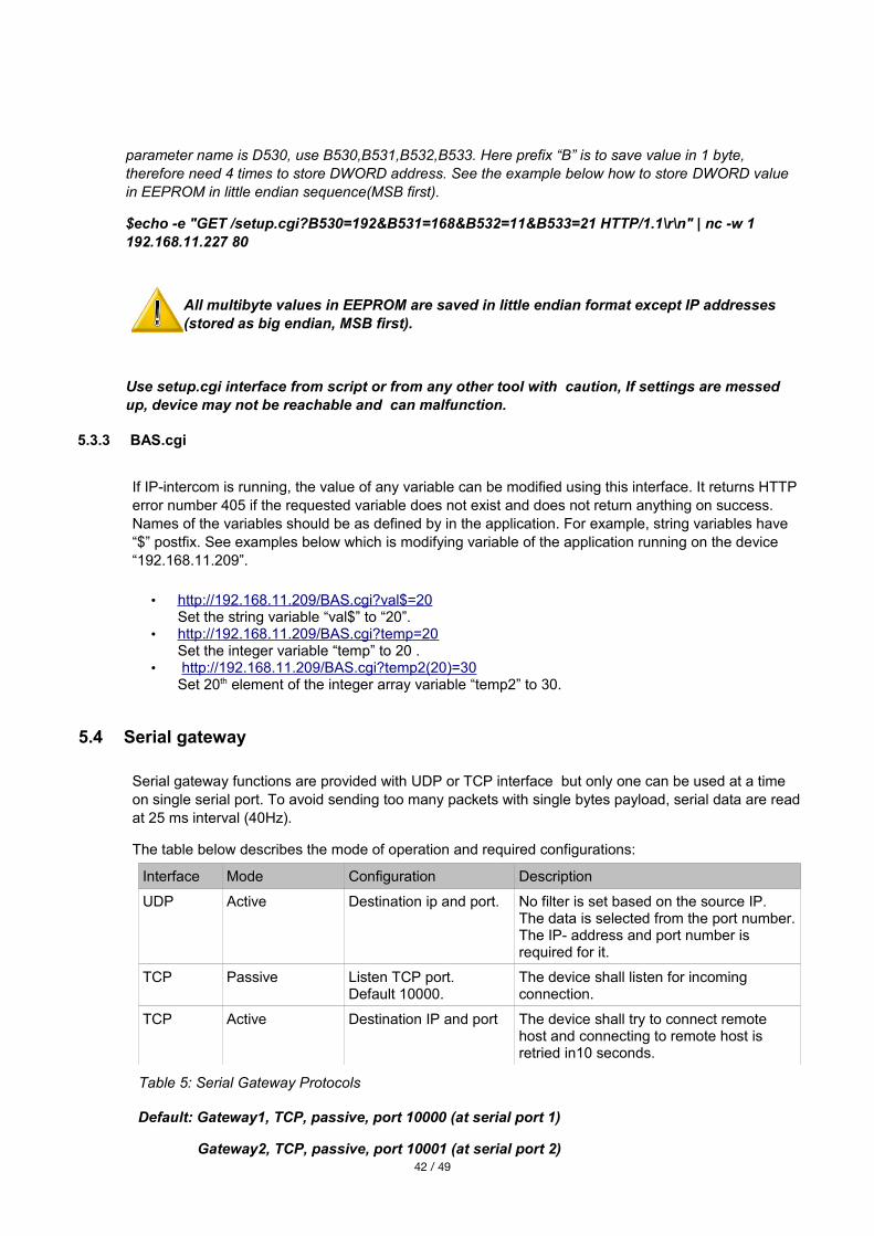
If IP-intercom is running, the value of any variable can be modified using this interface. It returns HTTPerror number 405 if the requested variable does not exist and does not return anything on success. Names of the variables should be as defined by in the application. For example, string variables have “$” postfix. See examples below which is modifying variable of the application running on the device “192.168.11.209”.
• http://192.168.11.209/BAS.cgi?val$=20 Set the string variable “val$” to “20”.
• http://192.168.11.209/BAS.cgi?temp=20 Set the integer variable “temp” to 20 .
• http://192.168.11.209/BAS.cgi?temp2(20)=30Set 20th element of the integer array variable “temp2” to 30.
5.4 Serial gateway
Serial gateway functions are provided with UDP or TCP interface but only one can be used at a time on single serial port. To avoid sending too many packets with single bytes payload, serial data are readat 25 ms interval (40Hz).
The table below describes the mode of operation and required configurations:
Interface Mode Configuration Description
UDP Active Destination ip and port. No filter is set based on the source IP. The data is selected from the port number.The IP- address and port number is required for it.
TCP Passive Listen TCP port. Default 10000.
The device shall listen for incoming connection.
TCP Active Destination IP and port The device shall try to connect remote host and connecting to remote host is retried in10 seconds.
Table 5: Serial Gateway Protocols
Default: Gateway1, TCP, passive, port 10000 (at serial port 1)
Gateway2, TCP, passive, port 10001 (at serial port 2) 42 / 49
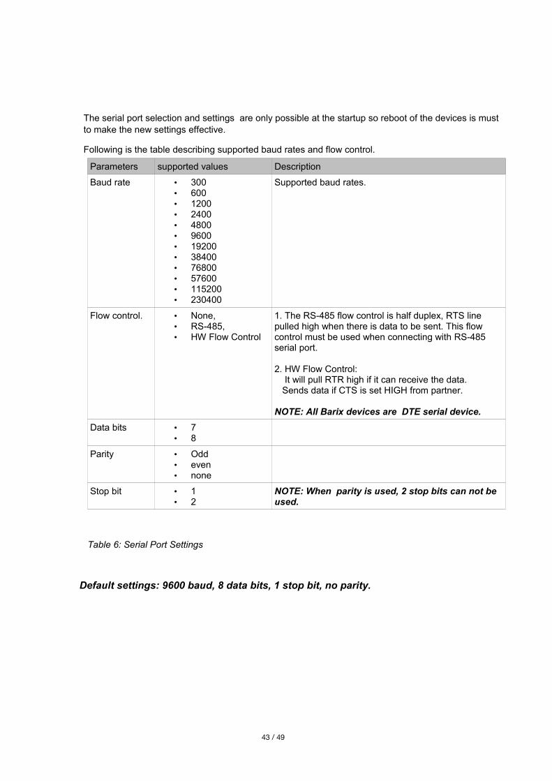
The serial port selection and settings are only possible at the startup so reboot of the devices is must to make the new settings effective.
Following is the table describing supported baud rates and flow control.
Parameters supported values Description
Baud rate • 300• 600• 1200• 2400• 4800• 9600• 19200• 38400• 76800• 57600• 115200• 230400
Supported baud rates.
Flow control. • None,• RS-485,• HW Flow Control
1. The RS-485 flow control is half duplex, RTS line pulled high when there is data to be sent. This flow control must be used when connecting with RS-485 serial port.
2. HW Flow Control: It will pull RTR high if it can receive the data. Sends data if CTS is set HIGH from partner.
NOTE: All Barix devices are DTE serial device.
Data bits • 7• 8
Parity • Odd• even• none
Stop bit • 1• 2
NOTE: When parity is used, 2 stop bits can not be used.
Table 6: Serial Port Settings
Default settings: 9600 baud, 8 data bits, 1 stop bit, no parity.
43 / 49
5.5 SNMP TRAPS
If configured, the device sends SNMP traps on input and relay status change. abcl trap 2 is sent on relay change and ABCL trap 4 is sent on input change.
Reported objects in trap are:
• system up time.
P(Public).1.3.0
• IO number.
E(Barix).unit(3).io(2).ioTable(1).ioEntry(1).ioIndex(1).Offset
• Value of IO.
E(Barix).unit(3).io(2).ioTable(1).ioEntry(1).ioValue(2).Offset
Here “E” is Barix Enterprise and “P” is public object.
5.6 Streaming
The streaming destinations can be set from the remote control panel using the command interface or can be configured from the web UI. The destination set from the command interface is not stored in theEEPROM. It will be lost if the device reboots. Only one destination can be set for the streaming at a time. The streaming destinations could be unicast, multicast or broadcast ip4 address. Any controller/PC host using command interface to start/stop the streaming may not be aware of the broadcast address of the device therefore ip address zero is considered to be broadcast address. Leaving IP address blank “0.0.0.0” and setting the destination port will stream audio as broadcast. When the RTP streaming mode is set to “RTP mode”, 4 LSB bytes of MAC address is used as identifier ( SSRC ) of the stream.
The IP-intercom operates in following modes and streams audio to configured destination. The streaming mode can be configured from the web UI and will be set only at startup. Changing mode requires the device to reboot to take new settings into effect.
1. Stream always
If the destination ip and port is set, audio stream shall be sent always to the configured destination. This streaming destinations can be overwritten by “stream to” command. Check thecommand table for details.
2. Stream on command .
Streams shall be sent to configured destination when device receives talk command “c=83” and stops streaming on command “c=84”.
3. Respond
The device will stream audio as long as it receives audio from any host. The host sending audioto it is selected as streaming destination.
4. Stream on Level
The device will start streaming audio when audio input level becomes above the threshold “Input Trigger Level”.
44 / 49
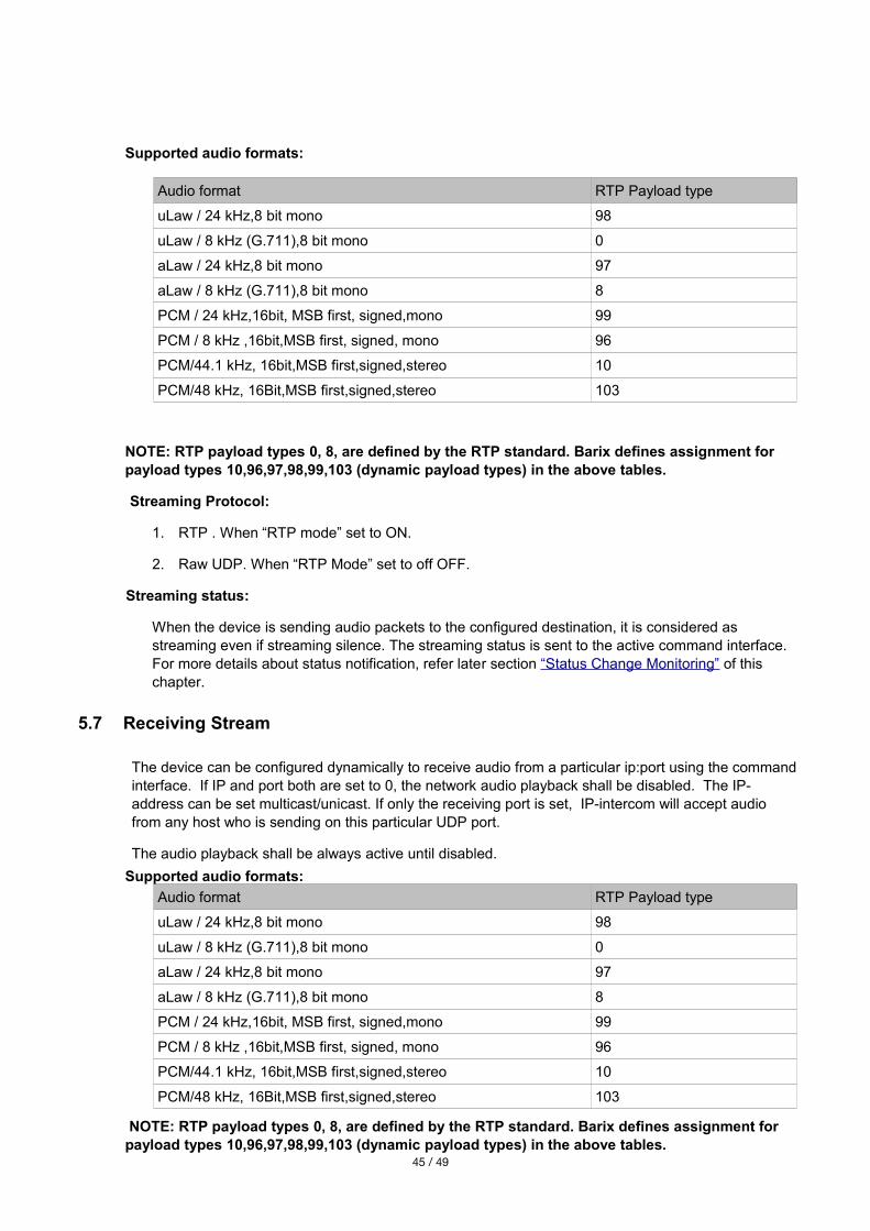
Supported audio formats:
Audio format RTP Payload type
uLaw / 24 kHz,8 bit mono 98
uLaw / 8 kHz (G.711),8 bit mono 0
aLaw / 24 kHz,8 bit mono 97
aLaw / 8 kHz (G.711),8 bit mono 8
PCM / 24 kHz,16bit, MSB first, signed,mono 99
PCM / 8 kHz ,16bit,MSB first, signed, mono 96
PCM/44.1 kHz, 16bit,MSB first,signed,stereo 10
PCM/48 kHz, 16Bit,MSB first,signed,stereo 103
NOTE: RTP payload types 0, 8, are defined by the RTP standard. Barix defines assignment for payload types 10,96,97,98,99,103 (dynamic payload types) in the above tables.
Streaming Protocol:
1. RTP . When “RTP mode” set to ON.
2. Raw UDP. When “RTP Mode” set to off OFF.
Streaming status:
When the device is sending audio packets to the configured destination, it is considered as streaming even if streaming silence. The streaming status is sent to the active command interface. For more details about status notification, refer later section “Status Change Monitoring” of this chapter.
5.7 Receiving Stream
The device can be configured dynamically to receive audio from a particular ip:port using the commandinterface. If IP and port both are set to 0, the network audio playback shall be disabled. The IP-address can be set multicast/unicast. If only the receiving port is set, IP-intercom will accept audio from any host who is sending on this particular UDP port.
The audio playback shall be always active until disabled.
Supported audio formats:
Audio format RTP Payload type
uLaw / 24 kHz,8 bit mono 98
uLaw / 8 kHz (G.711),8 bit mono 0
aLaw / 24 kHz,8 bit mono 97
aLaw / 8 kHz (G.711),8 bit mono 8
PCM / 24 kHz,16bit, MSB first, signed,mono 99
PCM / 8 kHz ,16bit,MSB first, signed, mono 96
PCM/44.1 kHz, 16bit,MSB first,signed,stereo 10
PCM/48 kHz, 16Bit,MSB first,signed,stereo 103
NOTE: RTP payload types 0, 8, are defined by the RTP standard. Barix defines assignment for payload types 10,96,97,98,99,103 (dynamic payload types) in the above tables.
45 / 49
Receive stream protocol:
1. RTP . When “RTP mode” set to ON.
2. Raw UDP . When “RTP Mode” set to off OFF.
if configured, relay one is closed during playback and opened after timeout.
5.8 Status Change Monitoring
The command interface provides commands to enquire the status of IO's,relays and streaming. If the TCP command port is connected or UDP remote command port is set, the input status, streaming/receiving and relay status are reported. The status changes are reported to only one interface. The TCP control port has priority. So If the TCP command interface is connected, status changes are reported to it, not over the UDP interface. The status monitoring is generic and supports all Barix hardware.
Command to get status: “q=all”.
See GETSTATUS command for more details.
5.9 Play a MP3 from ROM/USB file system
You can send the command “m=filename.mp3” to the device to play a mp3 audio files stored in flash (COB Files). Due to the limitations of the cob file structure, a audio files in flash can not be more than 64k. Playing a mp3 file from the local file system has more priority, so streaming/network playback will be stopped and resumed after finishing the local file playback. The flash is the default file system to play local file on request of the command “m=” . This can be changed by setting the application variable “file_sys_for_audio$” using “BAS.cgi” interface. Only mp3 audio files are supported.
Following is the supported file system and examples to play a local file.
Filesystem file_sys_for_audio$ Command example.
USB C_R:usb:// “m=/music/abc.mp3” to play music file “abc.mp3” from “music” folder.“m=/abc.mp3” to play music file “abc.mp3” from root folder.
ROM F_R: “m=baring.mp3”Note: flash filesystem does not contains any folders.
Table 7: Supported systems for the local playback
Refer “abcl technical documentation's guide” to get more details about WEB interfaces.
5.10 Syslog message
IP-intercom sends syslog message on crucial events as local network broadcast e. g. when new destination selected. The device can also be configured to send log messages to a remote host. Checkthe network settings to configure syslog remote host.
46 / 49
5.11 BCL Application
IP-intercom is developed using new features available in ABCL package version 1.xx which includes BCL interpreter version 1.5 . The Interpreter 1.5 is enhanced in many ways including length ofvariable names. IP-intercom application is utilizing the enhanced features of it and therefore can not be tokenized with previous versions of tokenizers.
5.12 Using AiPhone
Use of AiPhone panels are supported by only Annuncicom-200. User seeking to use AiPhone panel with IP-intercom software must use this hardware.
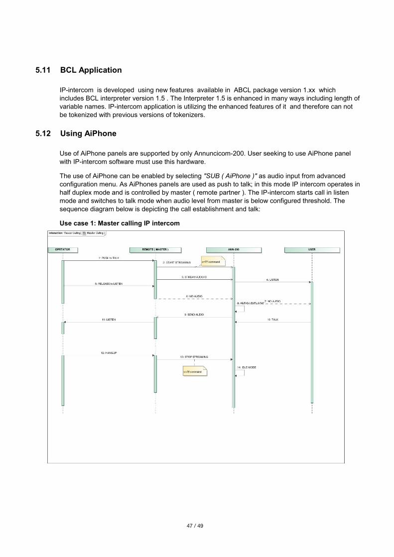
The use of AiPhone can be enabled by selecting "SUB ( AiPhone )" as audio input from advanced configuration menu. As AiPhones panels are used as push to talk; in this mode IP intercom operates inhalf duplex mode and is controlled by master ( remote partner ). The IP-intercom starts call in listen mode and switches to talk mode when audio level from master is below configured threshold. The sequence diagram below is depicting the call establishment and talk:
Use case 1: Master calling IP intercom
47 / 49
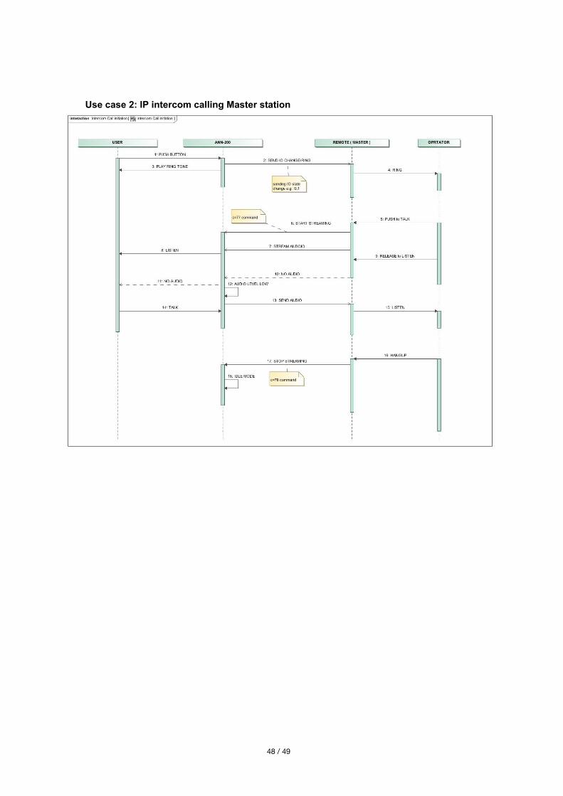
Use case 2: IP intercom calling Master station
48 / 49
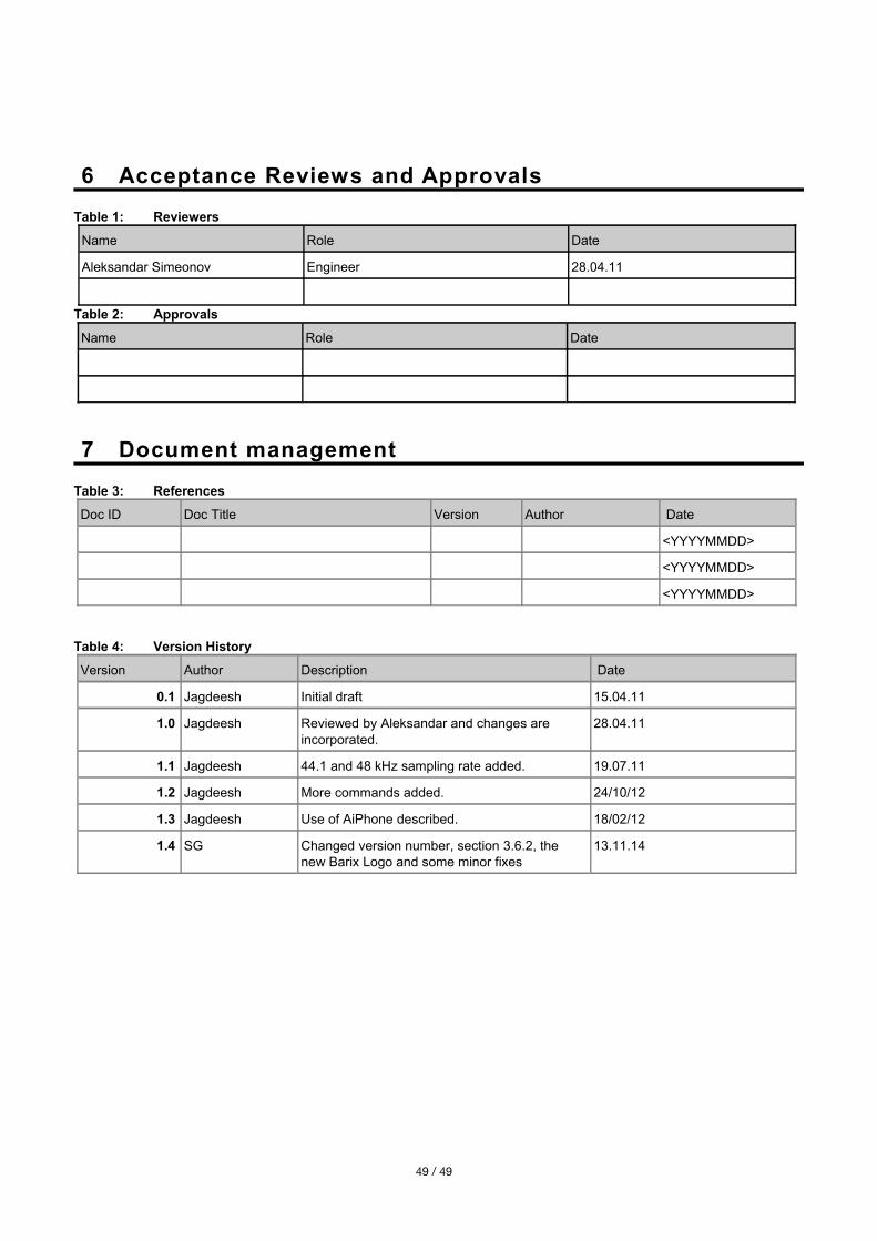
6 Acceptance Reviews and Approvals
Table 1: Reviewers
Name Role Date
Aleksandar Simeonov Engineer 28.04.11
Table 2: Approvals
Name Role Date
7 Document management
Table 3: References
Doc ID Doc Title Version Author Date
<YYYYMMDD>
<YYYYMMDD>
<YYYYMMDD>
Table 4: Version History
Version Author Description Date
0.1 Jagdeesh Initial draft 15.04.11
1.0 Jagdeesh Reviewed by Aleksandar and changes are incorporated.
28.04.11
1.1 Jagdeesh 44.1 and 48 kHz sampling rate added. 19.07.11
1.2 Jagdeesh More commands added. 24/10/12
1.3 Jagdeesh Use of AiPhone described. 18/02/12
1.4 SG Changed version number, section 3.6.2, the new Barix Logo and some minor fixes
13.11.14
49 / 49