Embed Size (px)
Citation preview
Application of Ultra High Capacity ConSep Trays for Debottlenecking of Gas and Ethylene Plant Fractionation Trains
by
Waldo de Villiers, Shell Global Solutions (US), Inc.
Peter Wilkinson, Shell Global Solutions International, Amsterdam, NL Daniel Summers, Sulzer Chemtech, Tulsa, OK
Presented at the AIChE Spring meeting, 2005 in Atlanta, GA
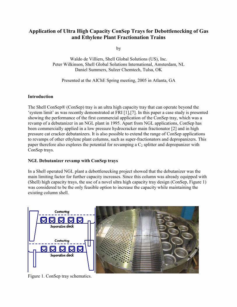
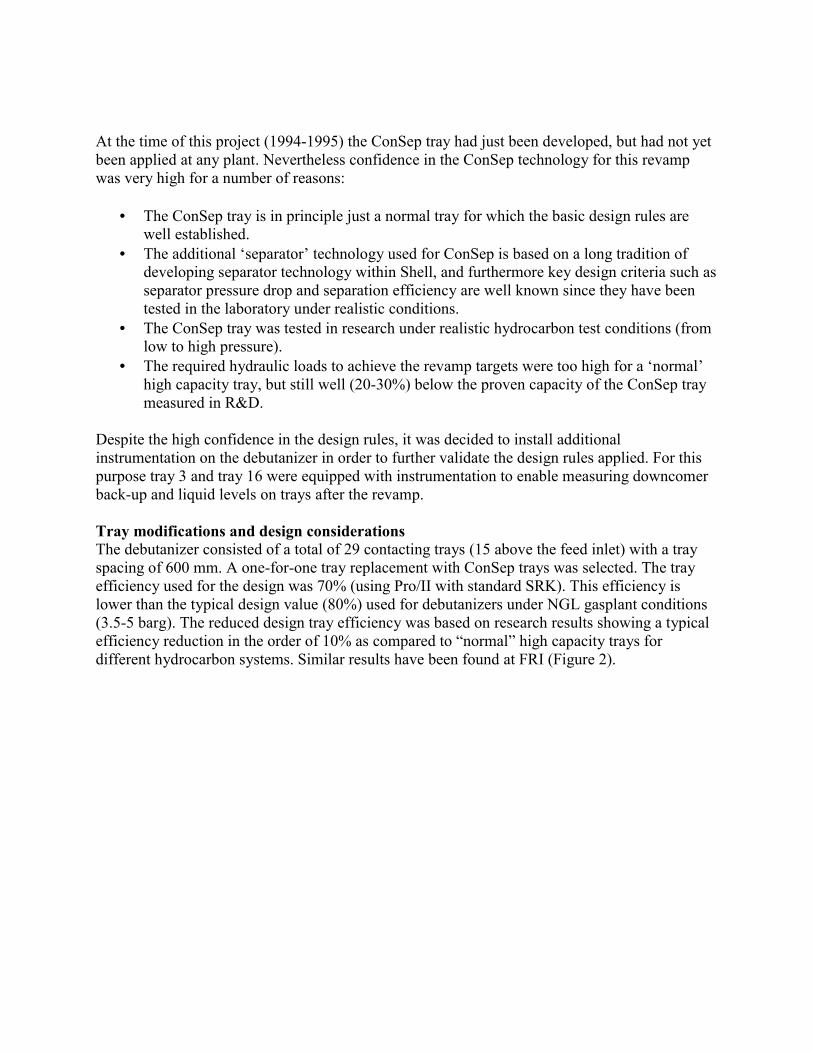
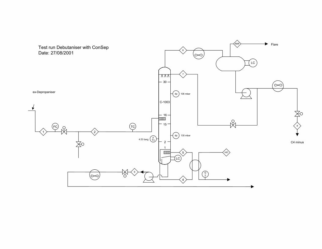
Introduction The Shell ConSep® (ConSep) tray is an ultra high capacity tray that can operate beyond the ‘system limit’ as was recently demonstrated at FRI [1],[7]. In this paper a case study is presented showing the performance of the first commercial application of the ConSep tray, which was a revamp of a debutanizer in an NGL plant in 1995. Apart from NGL applications, ConSep has been commercially applied in a low pressure hydrocracker main fractionator [2] and in high pressure cat cracker debutanizers. It is also possible to extend the range of ConSep applications to revamps of other ethylene plant columns, such as super-fractionators and depropanizers. This paper therefore also explores the potential for revamping a C2 splitter and depropanizer with ConSep trays. NGL Debutanizer revamp with ConSep trays In a Shell operated NGL plant a debottlenecking project showed that the debutanizer was the main limiting factor for further capacity increases. Since this column was already equipped with (Shell) high capacity trays, the use of a novel ultra high capacity tray design (ConSep, Figure 1) was considered to be the only feasible option to increase the capacity while maintaining the existing column shell.
����������
����������
��������� ����
��������� ����
����������
����������
��������� ����
��������� ����
Figure 1. ConSep tray schematics.
At the time of this project (1994-1995) the ConSep tray had just been developed, but had not yet been applied at any plant. Nevertheless confidence in the ConSep technology for this revamp was very high for a number of reasons:
• The ConSep tray is in principle just a normal tray for which the basic design rules are well established.
• The additional ‘separator’ technology used for ConSep is based on a long tradition of developing separator technology within Shell, and furthermore key design criteria such as separator pressure drop and separation efficiency are well known since they have been tested in the laboratory under realistic conditions.
• The ConSep tray was tested in research under realistic hydrocarbon test conditions (from low to high pressure).
• The required hydraulic loads to achieve the revamp targets were too high for a ‘normal’ high capacity tray, but still well (20-30%) below the proven capacity of the ConSep tray measured in R&D.
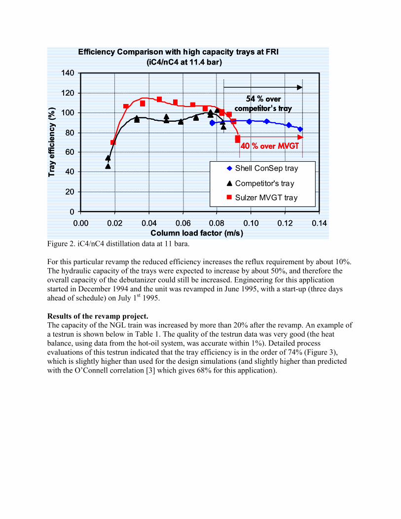
Despite the high confidence in the design rules, it was decided to install additional instrumentation on the debutanizer in order to further validate the design rules applied. For this purpose tray 3 and tray 16 were equipped with instrumentation to enable measuring downcomer back-up and liquid levels on trays after the revamp. Tray modifications and design considerations The debutanizer consisted of a total of 29 contacting trays (15 above the feed inlet) with a tray spacing of 600 mm. A one-for-one tray replacement with ConSep trays was selected. The tray efficiency used for the design was 70% (using Pro/II with standard SRK). This efficiency is lower than the typical design value (80%) used for debutanizers under NGL gasplant conditions (3.5-5 barg). The reduced design tray efficiency was based on research results showing a typical efficiency reduction in the order of 10% as compared to “normal” high capacity trays for different hydrocarbon systems. Similar results have been found at FRI (Figure 2).
Efficiency Comparison with high capacity trays at FRI (iC4/nC4 at 11.4 bar)
0
20
40
60
80
100
120
140
0.00 0.02 0.04 0.06 0.08 0.10 0.12 0.14Column load factor (m/s)
Tray
effi
cien
cy (%
)
Shell ConSep tray
Competitor's tray
Sulzer MVGT tray
�� � ������������ � ����
�� � ���� ����
Efficiency Comparison with high capacity trays at FRI (iC4/nC4 at 11.4 bar)
0
20
40
60
80
100
120
140
0.00 0.02 0.04 0.06 0.08 0.10 0.12 0.14Column load factor (m/s)
Tray
effi
cien
cy (%
)
Shell ConSep tray
Competitor's tray
Sulzer MVGT tray
�� � ������������ � ����
�� � ���� ����
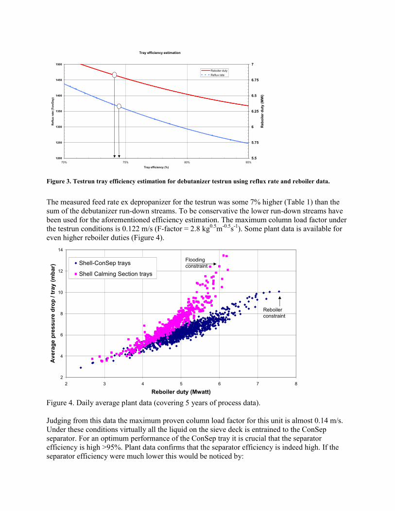
Figure 2. iC4/nC4 distillation data at 11 bara. For this particular revamp the reduced efficiency increases the reflux requirement by about 10%. The hydraulic capacity of the trays were expected to increase by about 50%, and therefore the overall capacity of the debutanizer could still be increased. Engineering for this application started in December 1994 and the unit was revamped in June 1995, with a start-up (three days ahead of schedule) on July 1st 1995. Results of the revamp project. The capacity of the NGL train was increased by more than 20% after the revamp. An example of a testrun is shown below in Table 1. The quality of the testrun data was very good (the heat balance, using data from the hot-oil system, was accurate within 1%). Detailed process evaluations of this testrun indicated that the tray efficiency is in the order of 74% (Figure 3), which is slightly higher than used for the design simulations (and slightly higher than predicted with the O’Connell correlation [3] which gives 68% for this application).
Tray efficiency estimation
1200
1250
1300
1350
1400
1450
1500
70% 75% 80% 85%
Tray efficiency (%)
Ref
lux
rate
(Ton
/Day
)
5.5
5.75
6
6.25
6.5
6.75
7
Reb
oile
r dut
y (M
W)
Reboiler dutyReflux rate
Figure 3. Testrun tray efficiency estimation for debutanizer testrun using reflux rate and reboiler data.
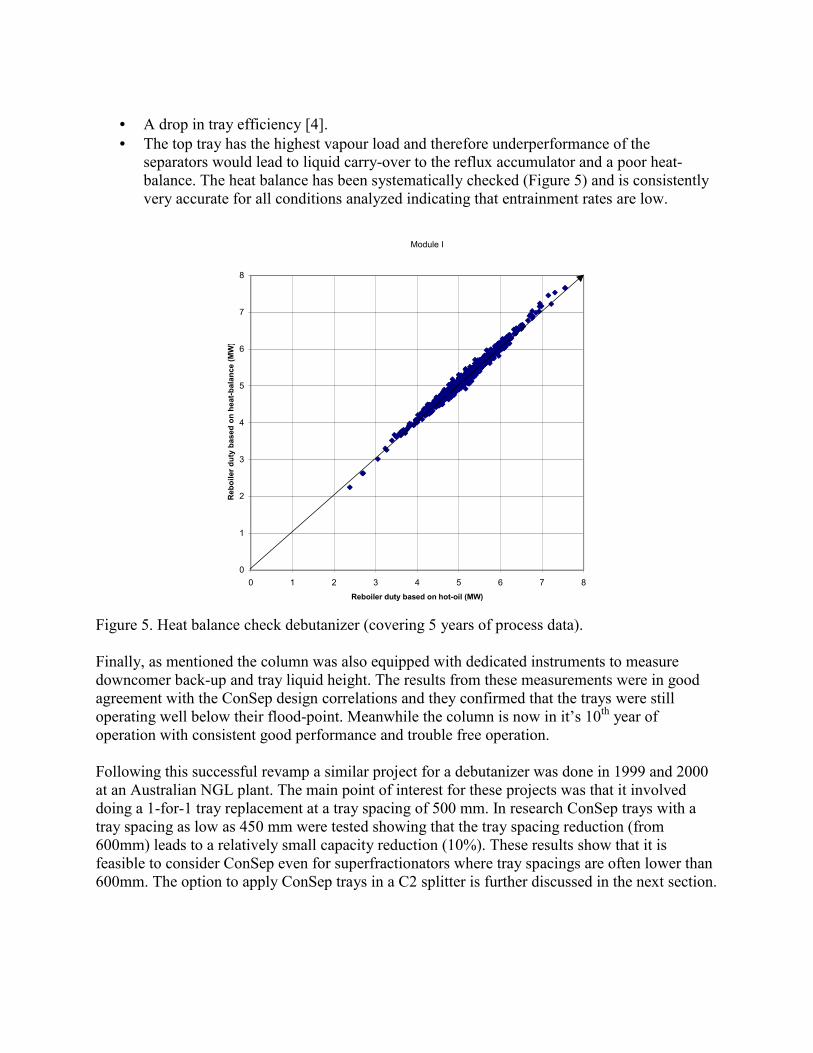
The measured feed rate ex depropanizer for the testrun was some 7% higher (Table 1) than the sum of the debutanizer run-down streams. To be conservative the lower run-down streams have been used for the aforementioned efficiency estimation. The maximum column load factor under the testrun conditions is 0.122 m/s (F-factor = 2.8 kg0.5m-0.5s-1). Some plant data is available for even higher reboiler duties (Figure 4).
2
4
6
8
10
12
14
2 3 4 5 6 7 8
Reboiler duty (Mwatt)
Ave
rage
pre
ssur
e dr
op /
tray
(mba
r) Shell-ConSep trays
Shell Calming Section trays
Flooding constraint
Reboiler constraint
Figure 4. Daily average plant data (covering 5 years of process data). Judging from this data the maximum proven column load factor for this unit is almost 0.14 m/s. Under these conditions virtually all the liquid on the sieve deck is entrained to the ConSep separator. For an optimum performance of the ConSep tray it is crucial that the separator efficiency is high >95%. Plant data confirms that the separator efficiency is indeed high. If the separator efficiency were much lower this would be noticed by:
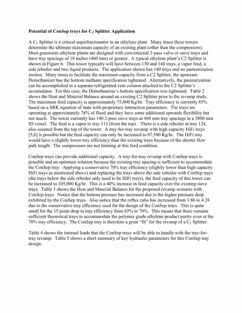
• A drop in tray efficiency [4]. • The top tray has the highest vapour load and therefore underperformance of the
separators would lead to liquid carry-over to the reflux accumulator and a poor heat-balance. The heat balance has been systematically checked (Figure 5) and is consistently very accurate for all conditions analyzed indicating that entrainment rates are low.
Module I
0
1
2
3
4
5
6
7
8
0 1 2 3 4 5 6 7 8Reboiler duty based on hot-oil (MW)
Reb
oile
r dut
y ba
sed
on h
eat-b
alan
ce (M
W)
Figure 5. Heat balance check debutanizer (covering 5 years of process data). Finally, as mentioned the column was also equipped with dedicated instruments to measure downcomer back-up and tray liquid height. The results from these measurements were in good agreement with the ConSep design correlations and they confirmed that the trays were still operating well below their flood-point. Meanwhile the column is now in it’s 10th year of operation with consistent good performance and trouble free operation. Following this successful revamp a similar project for a debutanizer was done in 1999 and 2000 at an Australian NGL plant. The main point of interest for these projects was that it involved doing a 1-for-1 tray replacement at a tray spacing of 500 mm. In research ConSep trays with a tray spacing as low as 450 mm were tested showing that the tray spacing reduction (from 600mm) leads to a relatively small capacity reduction (10%). These results show that it is feasible to consider ConSep even for superfractionators where tray spacings are often lower than 600mm. The option to apply ConSep trays in a C2 splitter is further discussed in the next section.
Potential of ConSep trays for C2 Splitter Application A C2 Splitter is a critical superfractionator in an ethylene plant. Many times these towers determine the ultimate maximum capacity of an existing plant (other than the compressors). Most grassroots ethylene plants are designed with conventional 2-pass valve or sieve trays and have tray spacings of 18 inches (460 mm) or greater. A typical ethylene plant’s C2 Splitter is shown in Figure 6. This tower typically will have between 130 and 140 trays, a vapor feed, a side reboiler and two liquid products. The application shown has 140 trays and no pasteurization section. Many times to facilitate the maximum capacity from a C2 Splitter, the upstream Demethanizer has the bottom methane specification tightened. Alternatively, the pasteurization can be accomplished in a separate refrigerated vent column attached to the C2 Splitter’s accumulator. For this case, the Demethanizer’s bottom specification was tightened. Table 2 shows the Heat and Material Balance around an existing C2 Splitter prior to the revamp study. The maximum feed capacity is approximately 75,000 Kg/hr. Tray efficiency is currently 85% based on a SRK equation of state with proprietary interaction parameters. The trays are operating at approximately 78% of flood and they have some additional upwards flexibility but not much. The tower currently has 140 2-pass sieve trays at 460 mm tray spacings in a 3800 mm ID vessel. The feed is a vapor to tray 113 (from the top). There is a side reboiler at tray 124, also counted from the top of the tower. A tray-for-tray revamp with high capacity HiFi trays [5,6] is possible but the feed capacity can only be increased to 87,500 Kg/hr. The HiFi tray would have a slightly lower tray efficiency than the existing trays because of the shorter flow path length. The compressors are not limiting at this feed condition. ConSep trays can provide additional capacity. A tray-for-tray revamp with ConSep trays is possible and an optimum solution because the existing tray spacing is sufficient to accommodate the ConSep tray. Applying a conservative 70% tray efficiency (slightly lower than high capacity HiFi trays as mentioned above) and replacing the trays above the side reboiler with ConSep trays (the trays below the side reboiler only need to be HiFi trays), the feed capacity of this tower can be increased to 105,000 Kg/hr. This is a 40% increase in feed capacity over the existing sieve trays. Table 3 shows the Heat and Material Balance for the proposed revamp scenario with ConSep trays. Notice that the bottom pressure has increased due to the higher pressure drop exhibited by the ConSep trays. Also notice that the reflux ratio has increased from 3.86 to 4.28 due to the conservative tray efficiency used for the design of the ConSep trays. This is quite small for the 15 point drop in tray efficiency from 85% to 70%. This means that there remains sufficient theoretical trays to accommodate the polymer grade ethylene product purity even at the 70% tray efficiency. The ConSep tray is therefore a great “fit” for the revamp of a C2 Splitter. Table 4 shows the internal loads that the ConSep trays will be able to handle with the tray-for-tray revamp. Table 5 shows a short summary of key hydraulic parameters for this ConSep tray design.
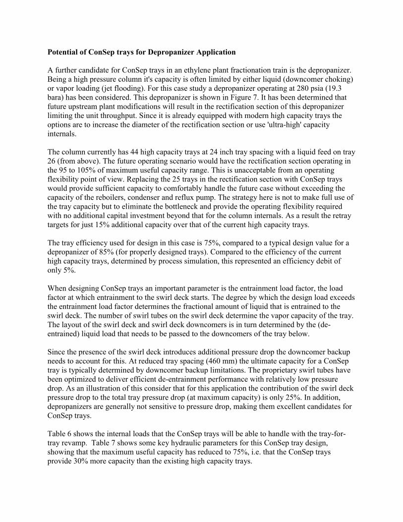
Potential of ConSep trays for Depropanizer Application A further candidate for ConSep trays in an ethylene plant fractionation train is the depropanizer. Being a high pressure column it's capacity is often limited by either liquid (downcomer choking) or vapor loading (jet flooding). For this case study a depropanizer operating at 280 psia (19.3 bara) has been considered. This depropanizer is shown in Figure 7. It has been determined that future upstream plant modifications will result in the rectification section of this depropanizer limiting the unit throughput. Since it is already equipped with modern high capacity trays the options are to increase the diameter of the rectification section or use 'ultra-high' capacity internals. The column currently has 44 high capacity trays at 24 inch tray spacing with a liquid feed on tray 26 (from above). The future operating scenario would have the rectification section operating in the 95 to 105% of maximum useful capacity range. This is unacceptable from an operating flexibility point of view. Replacing the 25 trays in the rectification section with ConSep trays would provide sufficient capacity to comfortably handle the future case without exceeding the capacity of the reboilers, condenser and reflux pump. The strategy here is not to make full use of the tray capacity but to eliminate the bottleneck and provide the operating flexibility required with no additional capital investment beyond that for the column internals. As a result the retray targets for just 15% additional capacity over that of the current high capacity trays. The tray efficiency used for design in this case is 75%, compared to a typical design value for a depropanizer of 85% (for properly designed trays). Compared to the efficiency of the current high capacity trays, determined by process simulation, this represented an efficiency debit of only 5%. When designing ConSep trays an important parameter is the entrainment load factor, the load factor at which entrainment to the swirl deck starts. The degree by which the design load exceeds the entrainment load factor determines the fractional amount of liquid that is entrained to the swirl deck. The number of swirl tubes on the swirl deck determine the vapor capacity of the tray. The layout of the swirl deck and swirl deck downcomers is in turn determined by the (de-entrained) liquid load that needs to be passed to the downcomers of the tray below. Since the presence of the swirl deck introduces additional pressure drop the downcomer backup needs to account for this. At reduced tray spacing (460 mm) the ultimate capacity for a ConSep tray is typically determined by downcomer backup limitations. The proprietary swirl tubes have been optimized to deliver efficient de-entrainment performance with relatively low pressure drop. As an illustration of this consider that for this application the contribution of the swirl deck pressure drop to the total tray pressure drop (at maximum capacity) is only 25%. In addition, depropanizers are generally not sensitive to pressure drop, making them excellent candidates for ConSep trays. Table 6 shows the internal loads that the ConSep trays will be able to handle with the tray-for-tray revamp. Table 7 shows some key hydraulic parameters for this ConSep tray design, showing that the maximum useful capacity has reduced to 75%, i.e. that the ConSep trays provide 30% more capacity than the existing high capacity trays.
References 1. "Test of Shell ConSep Tray", Topical Report 156, July 2004, Fractionation Research, Inc.
(available to FRI members only). 2. C. Groenendaal, B. Trautims, K. Kusters and J.L. Bravo. "The Shell ConSep Tray
Technology Provides Unparalleled Distillation Capacity". Presented at the EFChE Conference, April 2001, in Bamberg, Germany.
3. H.E. O'Connell, Trans. AIChE 42, p. 741, 1946 4. Lockett, M. J., Rahman, M. A. and Dhulesia, H. A. (1983). The effect of entrainment on
distillation tray efficiency, Chem. Engng. Sci. Vol 38, p. 661 5. D.R. Summers, K.G. Moore and R. Maisonneuve, “Properly Designed High Performance
Trays Increase Column Efficiency And Capacity”. Presented at the AIChE Spring National Meeting, March 12, 2002, New Orleans, Louisiana (Unpublished)
6. D.R. Summers, R. Alario, J. Broz, “High Performance Trays Increase Column Capacity and Efficiency” presented at the AIChE Spring National Meeting, April 2, 2003 New Orleans, Louisiana (Unpublished)
7. W.E. de Villiers, P.M. Wilkinson, J.L. Bravo, D.R. Summers, "Further Advances in Light Hydrocarbon Fractionation", PTQ, Summer 2004.
1
LC
LC
C-1003
30
16
15
C4 minus2
Flare
ex-Depropaniser
21
FC TC
5
6
8
7
NNF
HO
9
4
dp
dp
Q2
130 mbar
106 mbar
Test run Debutaniser with ConSepDate: 27/08/2001
pT34.53 barg
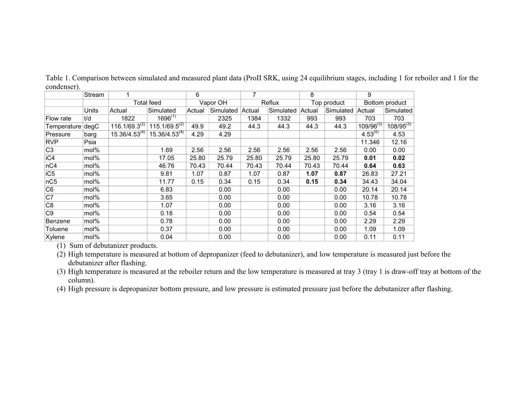
Table 1. Comparison between simulated and measured plant data (ProII SRK, using 24 equilibrium stages, including 1 for reboiler and 1 for the condenser).
Stream 1 6 7 8 9 Total feed Vapor OH Reflux Top product Bottom product Units Actual Simulated Actual Simulated Actual Simulated Actual Simulated Actual Simulated
Flow rate t/d 1822 1696(1) 2325 1384 1332 993 993 703 703 Temperature degC 116.1/69.3(2) 115.1/69.5(2) 49.9 49.2 44.3 44.3 44.3 44.3 109/96(3) 108/95(3) Pressure barg 15.36/4.53(4) 15.36/4.53(4) 4.29 4.29 4.53(5) 4.53 RVP Psia 11.346 12.16 C3 mol% 1.69 2.56 2.56 2.56 2.56 2.56 2.56 0.00 0.00 iC4 mol% 17.05 25.80 25.79 25.80 25.79 25.80 25.79 0.01 0.02 nC4 mol% 46.76 70.43 70.44 70.43 70.44 70.43 70.44 0.64 0.63 iC5 mol% 9.81 1.07 0.87 1.07 0.87 1.07 0.87 26.83 27.21 nC5 mol% 11.77 0.15 0.34 0.15 0.34 0.15 0.34 34.43 34.04 C6 mol% 6.83 0.00 0.00 0.00 20.14 20.14 C7 mol% 3.65 0.00 0.00 0.00 10.78 10.78 C8 mol% 1.07 0.00 0.00 0.00 3.16 3.16 C9 mol% 0.18 0.00 0.00 0.00 0.54 0.54 Benzene mol% 0.78 0.00 0.00 0.00 2.29 2.29 Toluene mol% 0.37 0.00 0.00 0.00 1.09 1.09 Xylene mol% 0.04 0.00 0.00 0.00 0.11 0.11
(1) Sum of debutanizer products. (2) High temperature is measured at bottom of depropanizer (feed to debutanizer), and low temperature is measured just before the
debutanizer after flashing. (3) High temperature is measured at the reboiler return and the low temperature is measured at tray 3 (tray 1 is draw-off tray at bottom of the
column). (4) High pressure is depropanizer bottom pressure, and low pressure is estimated pressure just before the debutanizer after flashing.
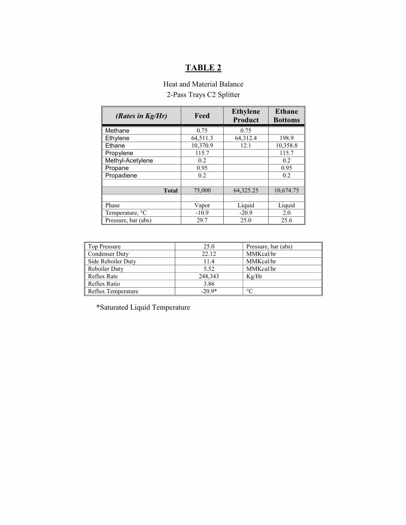
TABLE 2
Heat and Material Balance 2-Pass Trays C2 Splitter
(Rates in Kg/Hr) Feed Ethylene Product
Ethane Bottoms
Methane 0.75 0.75 Ethylene 64,511.3 64,312.4 198.9 Ethane 10,370.9 12.1 10,358.8 Propylene 115.7 115.7 Methyl-Acetylene 0.2 0.2 Propane 0.95 0.95 Propadiene 0.2 0.2
Total 75,000 64,325.25 10,674.75 Phase Vapor Liquid Liquid Temperature, °C -10.9 -20.9 2.0 Pressure, bar (abs) 29.7 25.0 25.6
Top Pressure 25.0 Pressure, bar (abs) Condenser Duty 22.12 MMKcal/hr Side Reboiler Duty 11.4 MMKcal/hr Reboiler Duty 5.52 MMKcal/hr Reflux Rate 248,343 Kg/Hr Reflux Ratio 3.86 Reflux Temperature -20.9* °C
*Saturated Liquid Temperature
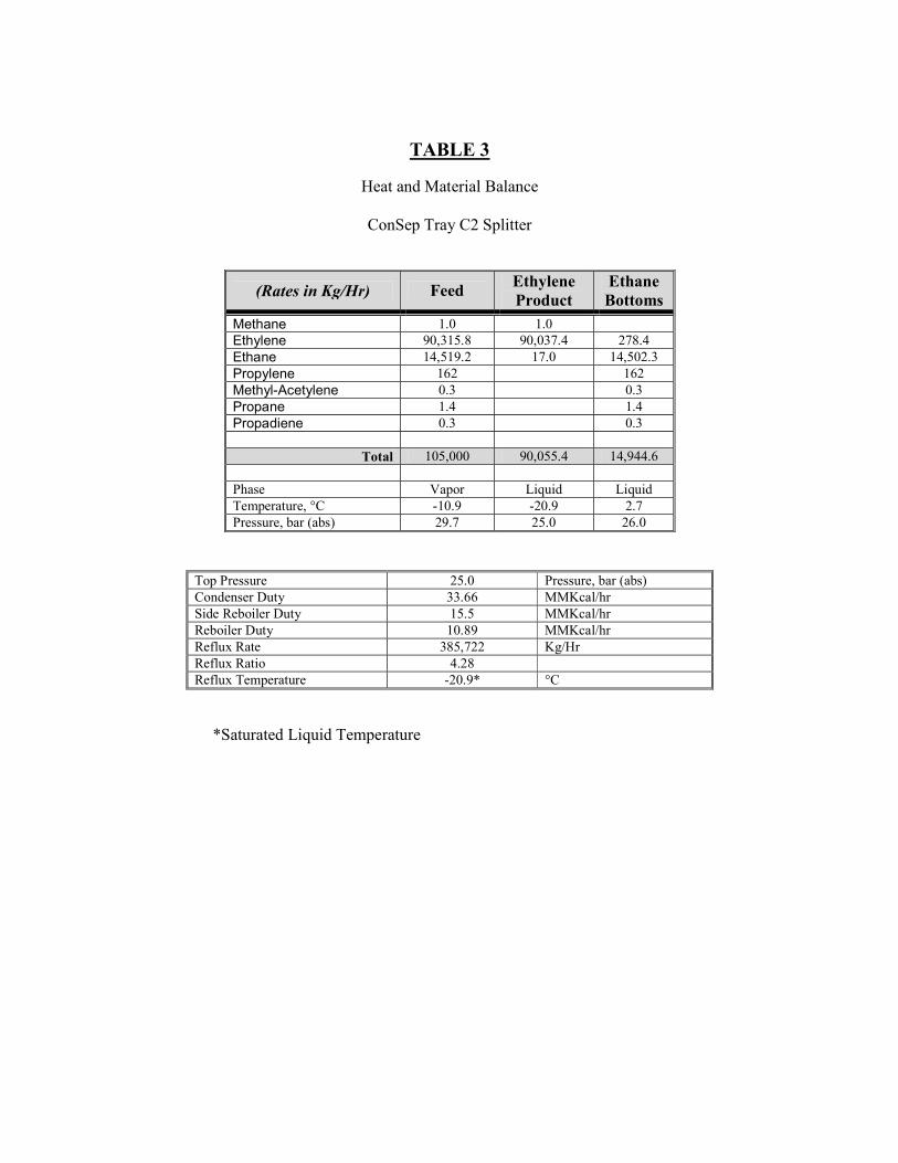
TABLE 3
Heat and Material Balance
ConSep Tray C2 Splitter
(Rates in Kg/Hr) Feed Ethylene Product
Ethane Bottoms
Methane 1.0 1.0 Ethylene 90,315.8 90,037.4 278.4 Ethane 14,519.2 17.0 14,502.3 Propylene 162 162 Methyl-Acetylene 0.3 0.3 Propane 1.4 1.4 Propadiene 0.3 0.3
Total 105,000 90,055.4 14,944.6 Phase Vapor Liquid Liquid Temperature, °C -10.9 -20.9 2.7 Pressure, bar (abs) 29.7 25.0 26.0
Top Pressure 25.0 Pressure, bar (abs) Condenser Duty 33.66 MMKcal/hr Side Reboiler Duty 15.5 MMKcal/hr Reboiler Duty 10.89 MMKcal/hr Reflux Rate 385,722 Kg/Hr Reflux Ratio 4.28 Reflux Temperature -20.9* °C
*Saturated Liquid Temperature
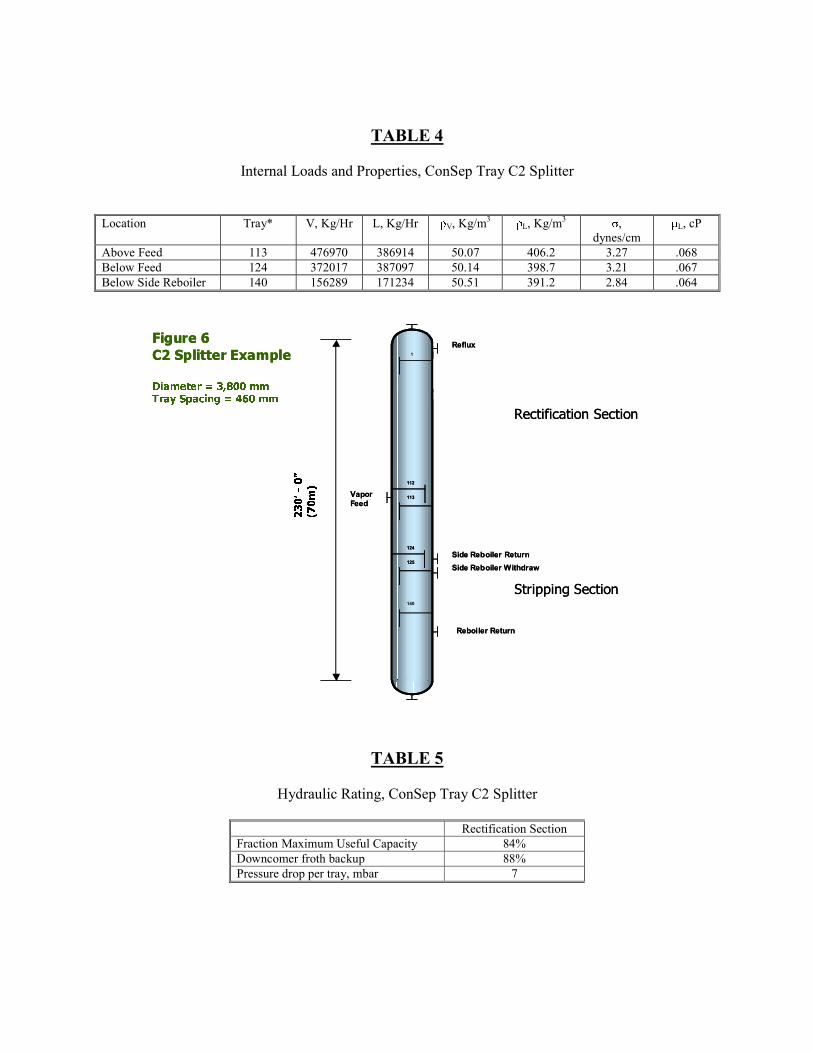
TABLE 4
Internal Loads and Properties, ConSep Tray C2 Splitter
Location Tray* V, Kg/Hr L, Kg/Hr �V, Kg/m3 �L, Kg/m3 �, dynes/cm
�L, cP
Above Feed 113 476970 386914 50.07 406.2 3.27 .068 Below Feed 124 372017 387097 50.14 398.7 3.21 .067 Below Side Reboiler 140 156289 171234 50.51 391.2 2.84 .064
VaporFeed
Reflux
Side Reboiler ReturnSide Reboiler Withdraw
Reboiler Return
1
112
113
124
125
140
������ �
� ��� �� �������
�� ������� � � ���� �� ���� ����� �� � � � ��� � ��
������������ �����
������ �����
�������
����
VaporFeed
Reflux
Side Reboiler ReturnSide Reboiler Withdraw
Reboiler Return
1
112
113
112
113
124
125
124
125
140
������ �
� ��� �� �������
�� ������� � � ���� �� ���� ����� �� � � � ��� � ��
������������ �����
������ �����
�������
����
TABLE 5
Hydraulic Rating, ConSep Tray C2 Splitter
Rectification Section Fraction Maximum Useful Capacity 84% Downcomer froth backup 88% Pressure drop per tray, mbar 7
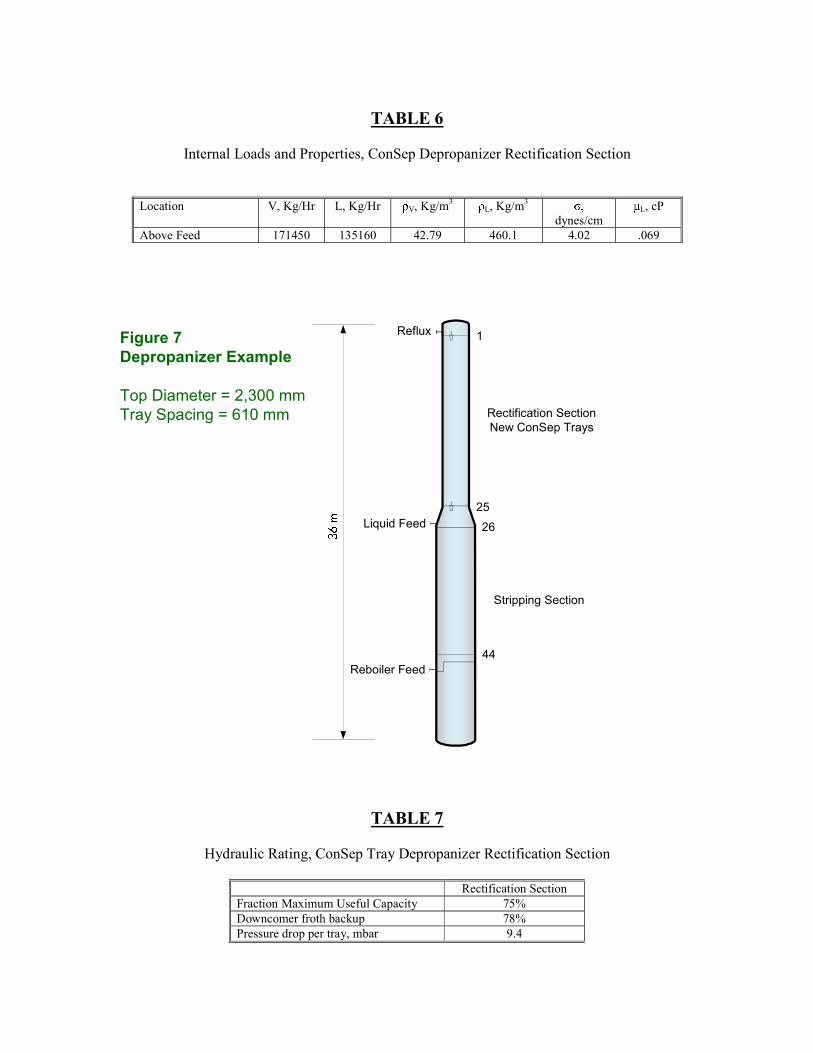
TABLE 6
Internal Loads and Properties, ConSep Depropanizer Rectification Section
Location V, Kg/Hr L, Kg/Hr �V, Kg/m3 �L, Kg/m3 � � �
dynes/cm �L, cP
Above Feed 171450 135160 42.79 460.1 4.02 .069
TABLE 7
Hydraulic Rating, ConSep Tray Depropanizer Rectification Section
Rectification Section Fraction Maximum Useful Capacity 75% Downcomer froth backup 78% Pressure drop per tray, mbar 9.4
Figure 7Depropanizer Example
Top Diameter = 2,300 mmTray Spacing = 610 mm
44
Stripping Section
26
25
Rectification SectionNew ConSep Trays
1
Liquid Feed����
Reflux
Reboiler Feed