Embed Size (px)
Citation preview
Journal for Technology of Plasticity, Vol. 32 (2007), Number 1-2
APPLICATION OF NET SHAPE AND NEAR-NET SHAPE FORMING TECHNOLOGIES IN MANUFACTURE OF
ROLLER BEARING COMPONENTS AND CARDAN SHAFTS
D Vilotić1., M Plančak1., K. Kuzman2, M.Milutinović1, D.Movrin1, P.Skakun1, O.Lužanin1
1University of Novi Sad, Faculty of Technical Sciences 2University of Ljubljana, Mechanical Engineering Faculty, Slovenia
ABSTRACT Analyzed in this paper are prospects of net shape and near-net shape forming technologies in manufacture of roller bearing components and cardan joints. Influence of elastic deformations of machine tool components on workpiece accuracy was analyzed based on case study of forming roller bearing axle. Key words: Net shape forming, Near net shape forming, Roll bearing, Cardans shaft, Elastic die deformation, Process simulation 1. INTRODUCTION Conventional technology of manufacturing roller bearing elements and cardan spindles is based on chip removal technologies which implies material losses and high costs of manufacture. Special problem with manufacture of roller bearing elements is that for each ring it requires a blank of tubular form with predifined dimensions, which in the case of a wide assortment of bearings, means hefty investment in material procurement. Cardan components (cardan cross and bearing, i.e. cardan bushing) are usually manufactured by forging, followed by machining. An alternative to these technologies are cold and hot plastic forming technologies. Roller bearing rings and components of cardan joints can be successfully manufactured using a variety of plastic forming technologies, such as forging, hot and cold rolling, extrusion, combined methods and, especially, net shape and near-net shape technologies.
Journal for Technology of Plasticity, Vol. 32 (2007), Number 1-2
88
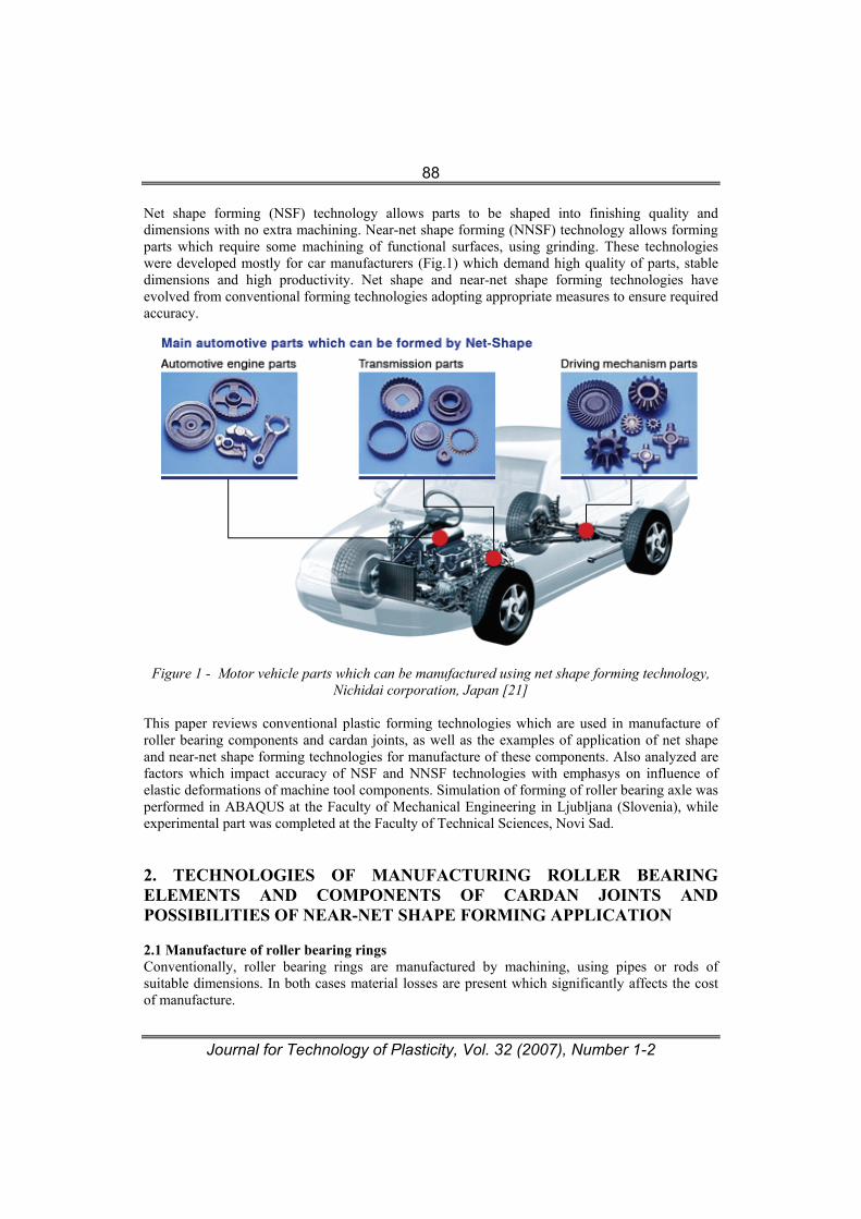
Net shape forming (NSF) technology allows parts to be shaped into finishing quality and dimensions with no extra machining. Near-net shape forming (NNSF) technology allows forming parts which require some machining of functional surfaces, using grinding. These technologies were developed mostly for car manufacturers (Fig.1) which demand high quality of parts, stable dimensions and high productivity. Net shape and near-net shape forming technologies have evolved from conventional forming technologies adopting appropriate measures to ensure required accuracy.
Figure 1 - Motor vehicle parts which can be manufactured using net shape forming technology, Nichidai corporation, Japan [21]
This paper reviews conventional plastic forming technologies which are used in manufacture of roller bearing components and cardan joints, as well as the examples of application of net shape and near-net shape forming technologies for manufacture of these components. Also analyzed are factors which impact accuracy of NSF and NNSF technologies with emphasys on influence of elastic deformations of machine tool components. Simulation of forming of roller bearing axle was performed in ABAQUS at the Faculty of Mechanical Engineering in Ljubljana (Slovenia), while experimental part was completed at the Faculty of Technical Sciences, Novi Sad. 2. TECHNOLOGIES OF MANUFACTURING ROLLER BEARING ELEMENTS AND COMPONENTS OF CARDAN JOINTS AND POSSIBILITIES OF NEAR-NET SHAPE FORMING APPLICATION
2.1 Manufacture of roller bearing rings Conventionally, roller bearing rings are manufactured by machining, using pipes or rods of suitable dimensions. In both cases material losses are present which significantly affects the cost of manufacture.
Journal for Technology of Plasticity, Vol. 32 (2007), Number 1-2
89
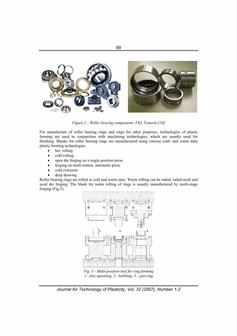
Figure 2 – Roller bearing components, FKL Temerin [10]
For manufacture of roller bearing rings and rings for other purposes, technologies of plastic forming are used in conjunction with machining technologies, which are usually used for finishing. Blanks for roller bearing rings are manufactured using various cold- and warm state plastic forming technologies:
• hot rolling • cold rolling • open die forging on a single position press • forging on multi-station automatic press • cold extrusion • deep drawing
Roller bearing rings are rolled in cold and warm state. Warm rolling can be radial, radial-axial and axial die forging. The blank for warm rolling of rings is usually manufactured by multi-stage forging (Fig.3).
Fig. 3 - Multi-position tool for ring forming 1 - free upsetting, 2 - hobbing, 3 – piercing
Journal for Technology of Plasticity, Vol. 32 (2007), Number 1-2
90
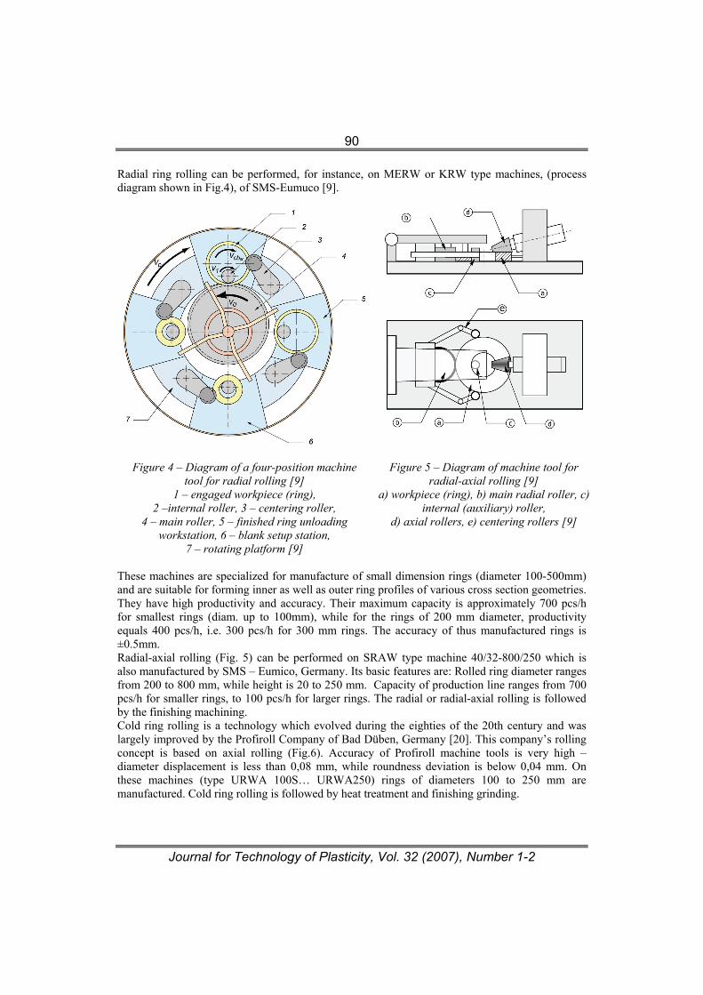
Radial ring rolling can be performed, for instance, on MERW or KRW type machines, (process diagram shown in Fig.4), of SMS-Eumuco [9].
Figure 4 – Diagram of a four-position machine
tool for radial rolling [9] 1 – engaged workpiece (ring),
2 –internal roller, 3 – centering roller, 4 – main roller, 5 – finished ring unloading
workstation, 6 – blank setup station, 7 – rotating platform [9]
Figure 5 – Diagram of machine tool for
radial-axial rolling [9] a) workpiece (ring), b) main radial roller, c)
internal (auxiliary) roller, d) axial rollers, e) centering rollers [9]
These machines are specialized for manufacture of small dimension rings (diameter 100-500mm) and are suitable for forming inner as well as outer ring profiles of various cross section geometries. They have high productivity and accuracy. Their maximum capacity is approximately 700 pcs/h for smallest rings (diam. up to 100mm), while for the rings of 200 mm diameter, productivity equals 400 pcs/h, i.e. 300 pcs/h for 300 mm rings. The accuracy of thus manufactured rings is ±0.5mm. Radial-axial rolling (Fig. 5) can be performed on SRAW type machine 40/32-800/250 which is also manufactured by SMS – Eumico, Germany. Its basic features are: Rolled ring diameter ranges from 200 to 800 mm, while height is 20 to 250 mm. Capacity of production line ranges from 700 pcs/h for smaller rings, to 100 pcs/h for larger rings. The radial or radial-axial rolling is followed by the finishing machining. Cold ring rolling is a technology which evolved during the eighties of the 20th century and was largely improved by the Profiroll Company of Bad Düben, Germany [20]. This company’s rolling concept is based on axial rolling (Fig.6). Accuracy of Profiroll machine tools is very high – diameter displacement is less than 0,08 mm, while roundness deviation is below 0,04 mm. On these machines (type URWA 100S… URWA250) rings of diameters 100 to 250 mm are manufactured. Cold ring rolling is followed by heat treatment and finishing grinding.
Journal for Technology of Plasticity, Vol. 32 (2007), Number 1-2
91
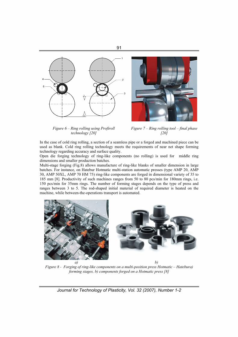
Figure 6 – Ring rolling using Profiroll
technology [20]
Figure 7 – Ring rolling tool – final phase
[20] In the case of cold ring rolling, a section of a seamless pipe or a forged and machined piece can be used as blank. Cold ring rolling technology meets the requirements of near net shape forming technology regarding accuracy and surface quality. Open die forging technology of ring-like components (no rolling) is used for middle ring dimensions and smaller production batches. Multi-stage forging (Fig.8) allows manufacture of ring-like blanks of smaller dimension in large batches. For instance, on Hatebur Hotmatic multi-station automatic presses (type AMP 20, AMP 30, AMP 50XL, AMP 70 HM 75) ring-like components are forged in dimensional variety of 35 to 185 mm [8]. Productivity of such machines ranges from 50 to 80 pcs/min for 180mm rings, i.e. 150 pcs/min for 35mm rings. The number of forming stages depends on the type of press and ranges between 3 to 5. The rod-shaped initial material of required diameter is heated on the machine, while between-the-operations transport is automated.
a) b) Figure 8 - Forging of ring-like components on a multi-position press Hotmatic – Hatebura)
forming stages, b) components forged on a Hotmatic press [8]
Journal for Technology of Plasticity, Vol. 32 (2007), Number 1-2
92
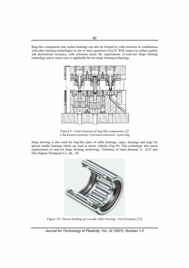
Ring-like components and cardan bushings can also be formed by cold extrusion in combination with other forming technologies in one or more operations (Fig.9). With respect to surface quality and dimensional accuracy, cold extrusion meets the requirements of near-net shape forming technology and in some cases is applicable for net shape forming technology.
Figure 9 - Cold extrusion of ring-like components [2] 1-backward extrusion, 2-forward extrusion, 3-piercing
Deep drawing is also used for ring-like parts of roller bearings, cages, housings and rings for special needle bearings which are used in motor vehicles (Fig.10). This technology also meets requirements of near-net shape forming technology. Tolerance of outer diameter is - 0,25 mm (Iko-Nippon Thompson Co., ltd., 14)
Figure 10 - Drawn bushing of a needle roller bearing - INA Germany [12]
Journal for Technology of Plasticity, Vol. 32 (2007), Number 1-2
93
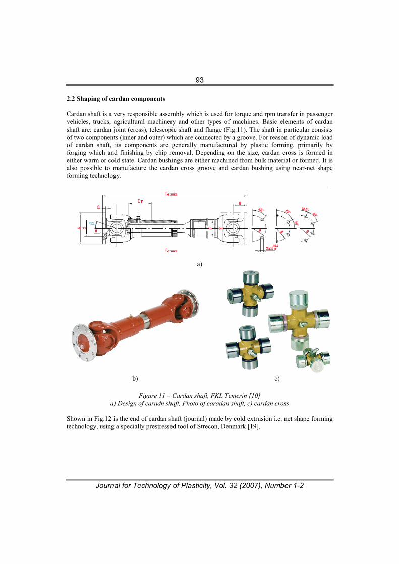
2.2 Shaping of cardan components Cardan shaft is a very responsible assembly which is used for torque and rpm transfer in passenger vehicles, trucks, agricultural machinery and other types of machines. Basic elements of cardan shaft are: cardan joint (cross), telescopic shaft and flange (Fig.11). The shaft in particular consists of two components (inner and outer) which are connected by a groove. For reason of dynamic load of cardan shaft, its components are generally manufactured by plastic forming, primarily by forging which and finishing by chip removal. Depending on the size, cardan cross is formed in either warm or cold state. Cardan bushings are either machined from bulk material or formed. It is also possible to manufacture the cardan cross groove and cardan bushing using near-net shape forming technology.
a)
b) c)
Figure 11 – Cardan shaft, FKL Temerin [10] a) Design of caradn shaft, Photo of caradan shaft, c) cardan cross
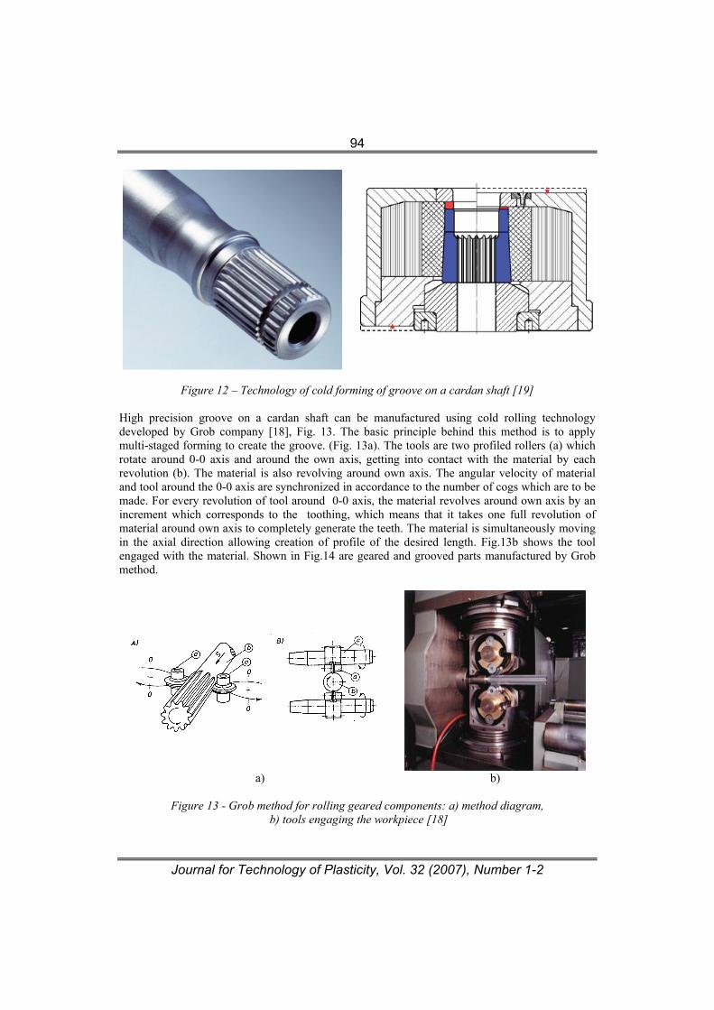
Shown in Fig.12 is the end of cardan shaft (journal) made by cold extrusion i.e. net shape forming technology, using a specially prestressed tool of Strecon, Denmark [19].
Journal for Technology of Plasticity, Vol. 32 (2007), Number 1-2
94
Figure 12 – Technology of cold forming of groove on a cardan shaft [19]
High precision groove on a cardan shaft can be manufactured using cold rolling technology developed by Grob company [18], Fig. 13. The basic principle behind this method is to apply multi-staged forming to create the groove. (Fig. 13a). The tools are two profiled rollers (a) which rotate around 0-0 axis and around the own axis, getting into contact with the material by each revolution (b). The material is also revolving around own axis. The angular velocity of material and tool around the 0-0 axis are synchronized in accordance to the number of cogs which are to be made. For every revolution of tool around 0-0 axis, the material revolves around own axis by an increment which corresponds to the toothing, which means that it takes one full revolution of material around own axis to completely generate the teeth. The material is simultaneously moving in the axial direction allowing creation of profile of the desired length. Fig.13b shows the tool engaged with the material. Shown in Fig.14 are geared and grooved parts manufactured by Grob method.
a) b)
Figure 13 - Grob method for rolling geared components: a) method diagram,
b) tools engaging the workpiece [18]
Journal for Technology of Plasticity, Vol. 32 (2007), Number 1-2
95
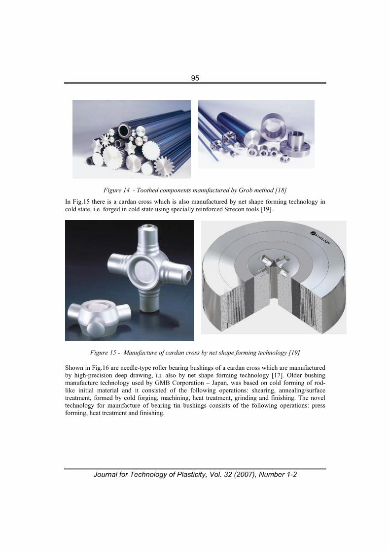
Figure 14 - Toothed components manufactured by Grob method [18]
In Fig.15 there is a cardan cross which is also manufactured by net shape forming technology in cold state, i.e. forged in cold state using specially reinforced Strecon tools [19].
Figure 15 - Manufacture of cardan cross by net shape forming technology [19]
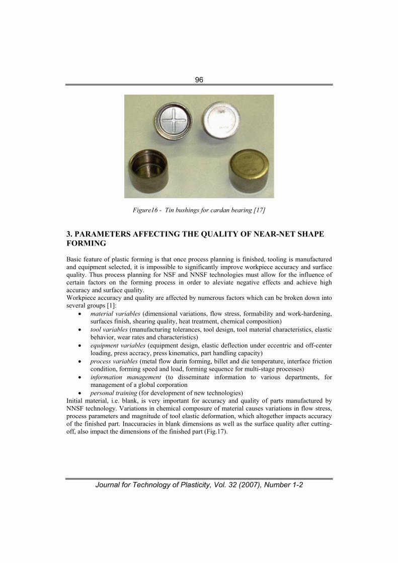
Shown in Fig.16 are needle-type roller bearing bushings of a cardan cross which are manufactured by high-precision deep drawing, i.i. also by net shape forming technology [17]. Older bushing manufacture technology used by GMB Corporation – Japan, was based on cold forming of rod-like initial material and it consisted of the following operations: shearing, annealing/surface treatment, formed by cold forging, machining, heat treatment, grinding and finishing. The novel technology for manufacture of bearing tin bushings consists of the following operations: press forming, heat treatment and finishing.
Journal for Technology of Plasticity, Vol. 32 (2007), Number 1-2
96
Figure16 - Tin bushings for cardan bearing [17] 3. PARAMETERS AFFECTING THE QUALITY OF NEAR-NET SHAPE FORMING Basic feature of plastic forming is that once process planning is finished, tooling is manufactured and equipment selected, it is impossible to significantly improve workpiece accuracy and surface quality. Thus process planning for NSF and NNSF technologies must allow for the influence of certain factors on the forming process in order to aleviate negative effects and achieve high accuracy and surface quality. Workpiece accuracy and quality are affected by numerous factors which can be broken down into several groups [1]:
• material variables (dimensional variations, flow stress, formability and work-hardening, surfaces finish, shearing quality, heat treatment, chemical composition)
• tool variables (manufacturing tolerances, tool design, tool material characteristics, elastic behavior, wear rates and characteristics)
• equipment variables (equipment design, elastic deflection under eccentric and off-center loading, press accracy, press kinematics, part handling capacity)
• process variables (metal flow durin forming, billet and die temperature, interface friction condition, forming speed and load, forming sequence for multi-stage processes)
• information management (to disseminate information to various departments, for management of a global corporation
• personal training (for development of new technologies) Initial material, i.e. blank, is very important for accuracy and quality of parts manufactured by NNSF technology. Variations in chemical composure of material causes variations in flow stress, process parameters and magnitude of tool elastic deformation, which altogether impacts accuracy of the finished part. Inaccuracies in blank dimensions as well as the surface quality after cutting-off, also impact the dimensions of the finished part (Fig.17).
Journal for Technology of Plasticity, Vol. 32 (2007), Number 1-2
97
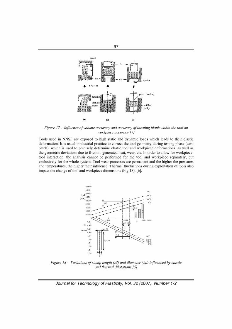
Figure 17 - Influence of volume accuracy and accuracy of locating blank within the tool on
workpiece accuracy [7]
Tools used in NNSF are exposed to high static and dynamic loads which leads to their elastic deformation. It is usual inndustrial practice to correct the tool geometry during testing phase (zero batch), which is used to precisely determine elastic tool and workpiece deformations, as well as the geometric deviations due to friction, generated heat, wear, etc. In order to allow for workpiece-tool interaction, the analysis cannot be performed for the tool and workpiece separately, but exclusively for the whole system. Tool wear processes are permanent and the higher the pressures and temperatures, the higher their influence. Thermal fluctuations during exploitation of tools also impact the change of tool and workpiece dimensions (Fig.18), [6].
Figure 18 - Variations of stamp length (Δl) and diameter (Δd) influenced by elastic
and thermal dilatations [5]
Journal for Technology of Plasticity, Vol. 32 (2007), Number 1-2
98
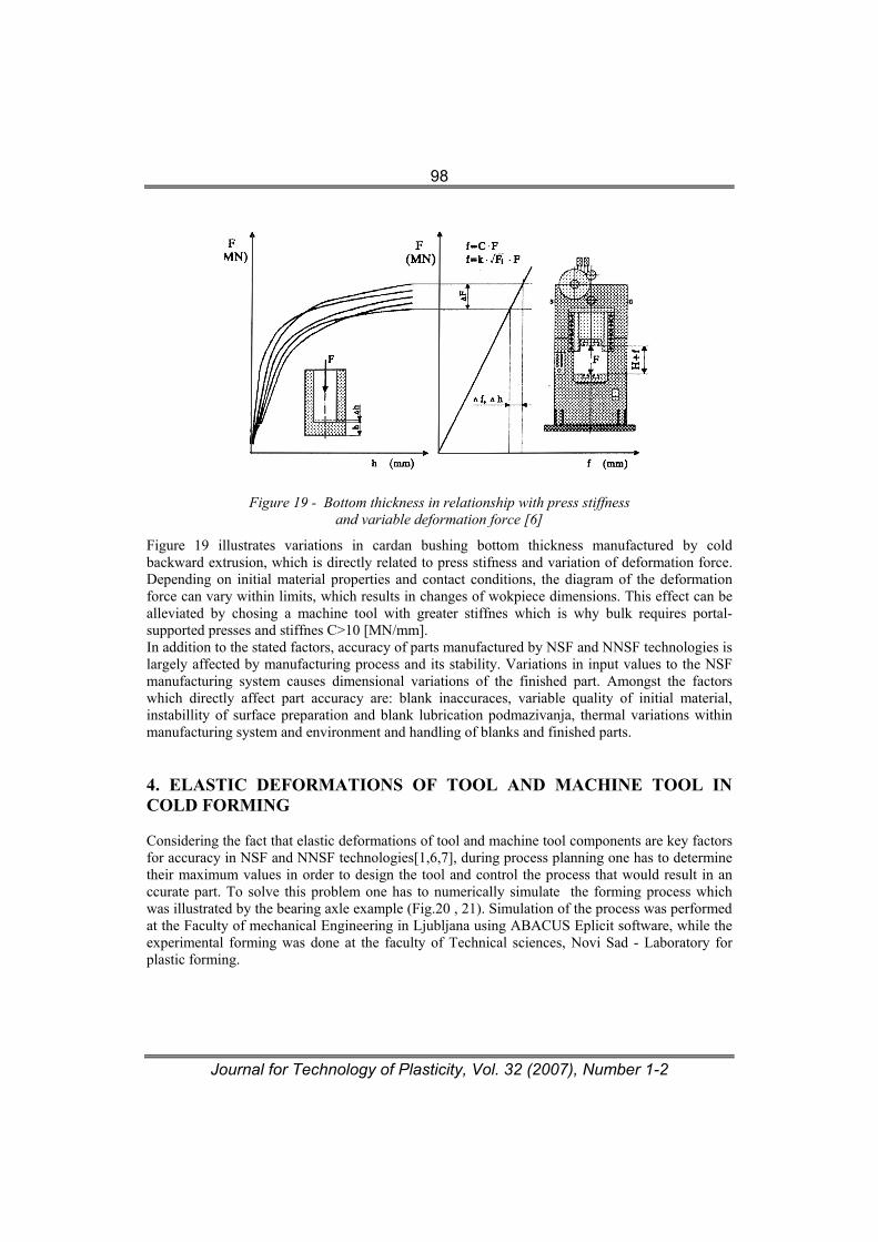
Figure 19 - Bottom thickness in relationship with press stiffness
and variable deformation force [6]
Figure 19 illustrates variations in cardan bushing bottom thickness manufactured by cold backward extrusion, which is directly related to press stifness and variation of deformation force. Depending on initial material properties and contact conditions, the diagram of the deformation force can vary within limits, which results in changes of wokpiece dimensions. This effect can be alleviated by chosing a machine tool with greater stiffnes which is why bulk requires portal-supported presses and stiffnes C>10 [MN/mm]. In addition to the stated factors, accuracy of parts manufactured by NSF and NNSF technologies is largely affected by manufacturing process and its stability. Variations in input values to the NSF manufacturing system causes dimensional variations of the finished part. Amongst the factors which directly affect part accuracy are: blank inaccuraces, variable quality of initial material, instabillity of surface preparation and blank lubrication podmazivanja, thermal variations within manufacturing system and environment and handling of blanks and finished parts. 4. ELASTIC DEFORMATIONS OF TOOL AND MACHINE TOOL IN COLD FORMING
Considering the fact that elastic deformations of tool and machine tool components are key factors for accuracy in NSF and NNSF technologies[1,6,7], during process planning one has to determine their maximum values in order to design the tool and control the process that would result in an ccurate part. To solve this problem one has to numerically simulate the forming process which was illustrated by the bearing axle example (Fig.20 , 21). Simulation of the process was performed at the Faculty of mechanical Engineering in Ljubljana using ABACUS Eplicit software, while the experimental forming was done at the faculty of Technical sciences, Novi Sad - Laboratory for plastic forming.
Journal for Technology of Plasticity, Vol. 32 (2007), Number 1-2
99
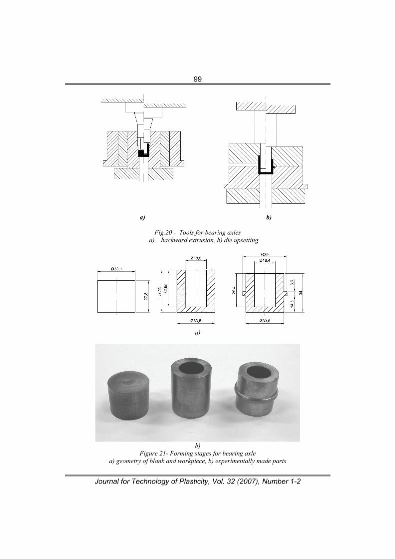
a) b)
Fig.20 - Tools for bearing axles a) backward extrusion, b) die upsetting
a)
b)
Figure 21- Forming stages for bearing axle a) geometry of blank and workpiece, b) experimentally made parts
Journal for Technology of Plasticity, Vol. 32 (2007), Number 1-2
100
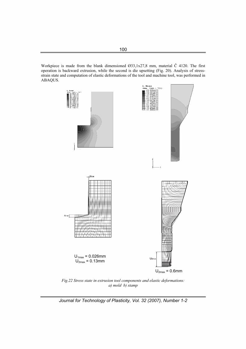
Workpiece is made from the blank dimensioned Ø33,1x27,8 mm, material Č 4120. The first operation is backward extrusion, while the second is die upsetting (Fig. 20). Analysis of stress-strain state and computation of elastic deformations of the tool and machine tool, was performed in ABAQUS.
U1max = 0.026mm U2max = 0.13mm
U2max = 0.6mm
Fig.22 Stress state in extrusion tool components and elastic deformations:
a) mold b) stamp
Journal for Technology of Plasticity, Vol. 32 (2007), Number 1-2
101
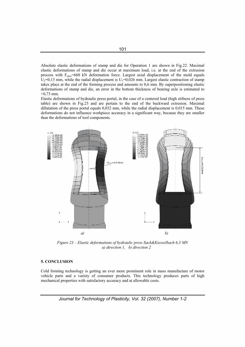
Absolute elastic deformations of stamp and die for Operation 1 are shown in Fig.22. Maximal elastic deformations of stamp and die occur at maximum load, i.e. at the end of the extrusion process with Fmax=660 kN deformation force. Largest axial displacement of the mold equals U2=0,13 mm, while the radial displacement is U1=0,026 mm. Largest elastic contraction of stamp takes place at the end of the forming process and amounts to 0,6 mm. By superpositioning elastic deformations of stamp and die, an error in the bottom thickness of bearing axle is estimated to +0,73 mm. Elastic deformations of hydraulic press portal, in the case of a centered load (high stifness of press table) are shown in Fig.23 and are pertain to the end of the backward extrusion. Maximal dillatation of the press portal equals 0,032 mm, while the radial displacement is 0,015 mm. These deformations do not influence workpiece accuracy in a significant way, because they are smaller than the deformations of tool components.
a) b)
Figure 23 – Elastic deformations of hydraulic press Sack&Kiesselbach 6,3 MN
a) direction 1, b) direction 2
5. CONCLUSION Cold forming technology is getting an ever more prominent role in mass manufacture of motor vehicle parts and a variety of consumer products. This technology produces parts of high mechanical properties with satisfactory accuracy and at allowable costs.
Journal for Technology of Plasticity, Vol. 32 (2007), Number 1-2
102
Further brekthrough in manufacture by plastic forming technologies was made by net shape and near-net shape forming technologies. The parts thus manufactured are of higher quality in comparison with parts obtained by conventional methods of cold forming. NSF and NNSF technologies are gaining popularity in manufacture of roller bearing components and cardan joints in industrially developed countries. However, their application requires far more subtler approach to planning and design of manufacturing process. Process planning for NSF and NNSF technologies requires identification of factors which influence product accuracy and quality in order to eliminate their negative impact. Of special importance to accuracy of parts which are produced by these technologies are elastic deformations of tooling and machine tool components, as well as elastic deformations of the workpiece. In order to eliminate the negative influence of elastic deformations which are inherent to NSF and NNSF technologies, simulation of the forming process is required as part of the modern approach to plastic forming process planning. Simulation of the forming process for the simple workpiece (bearing axle) in this paper, showed that elastic deformations of tool components – due to high specific load at the end of the extrusion process – are significant, namely, axial stamp contraction equals 0,13 mm while mold contraction is 0,6 mm, which results in the workpiece bottom thickness which exceeds nominal dimension by 0,73 mm. Simulation of press load in this case showed that the elastic deformations are almost negligible due to high machine tool stifness (C=20MN/mm) and a relatively low load (660 kN) at the end of the extrusion process. ACKNOWLEDGMENT Results of investigation presented in this paper are part of research within the project “Investigation, development and application of near net shape forming technology for production of bearing and cardan elements – TR 6333B”, financed by the Ministry of science of the Republic of Serbia. The authors are grateful for this financial support. REFERENCES [1] Altan T., Nagaile G., Shen G.: Cold and Hot Forging – Fundamentals and Applications, ASM
Materials, Ohio, 2005. [2] Lange K.: Handbook оf Metal Forming, McGraw-Hill, Inc., ISBN 0-07-036285-8, 1985. [3] Eberlein L.: Die Anwendung der Visioplastizität zur Spannungsermittlung beim Fliesspressen,
Information TU Dresden, 14,03,1979, [4] Spur G., Stöferle T.: Handbuch der Fertigunkstechnik, Umformen, Band 2/1, 2/2, 2/3, Carl
Hanser Verlag München, Wien, 1984. [5] Kuzman K.: Problems of accuracy control in cold forming, Journal of Materials Processing
Technology 113, pp 10-15, 2001. [6] Kuzman K., Štok B.: Total process control – A precondition for Net Shape Forming
implementation, Proceding of the 9th International Cold Forging Congress,pp 123-128, Solihull, UK, 1995.
[7] Kudo H.: Towards Net-Shape Forming, Journal of Materials Processing Technology 22, pp 307-342, 1990.
[8] www.hatebur.com [9] www.sms-demag.com [10] www.fkl.co.yu

Journal for Technology of Plasticity, Vol. 32 (2007), Number 1-2
103
[12] www.ina.com [13] www.jtekt.co.jp [14] www.ikont.co.jp [15] www.skf.com [16] www.fag.com [17] www.gmb.jp/technical/net_e.html [18] www.grobinc.com [19] www.strecon.com [20] www.profiroll.de [21] www.nichidai.jp/english/whats/netshape.html
Journal for Technology of Plasticity, Vol. 32 (2007), Number 1-2
PRIMENA NET SHAPE I NEAR-NET SHAPE FORMING TEHNOLOGIJA U PROIZVODNJI ELEMNATA
KOTRLJAJNIH LEŽAJA I KARDANA
D Vilotić1., M Plančak1., K. Kuzman2, M.Milutinović1, D.Movrin1, P.Skakun1, O.Lužanin1
1Univerzitet u Novom Sadu, Fakultet tehničkih nauka, Trg Dositeja Obradovića 6, Novi Sad Srbija 2Univerza v Ljubljani, Fakulteta za strojništvo, Aškerčeva 6, Ljubljana, Slovenia
REZIME
Tradicionalna tehnologija izrade elemenata kotrljajnih ležaja i kardana bazirana je na tehnologijama obrade skidanjem strugotine uz značajne gubitke materijala i visoke troškove proizvodnje. Elementi kardana (kardanski krst i ležaj, odnosno čašica ležaja) obično se proizvode kovanjem, nakon čega sledi obrada rezanjem. Alternativa ovim tehnologijama su tehnologije plastičnog deformisanja u hladnom i toplom stanju. Prstenovi ležajeva i elementi kardanskog zgloba mogu se uspešno proizvoditi primenom različitih metoda tehnologije plastičnog deformisanja, kao na primer, kovanjem, toplim i hladnim valjanjem, istiskivanjem i kombinovanim metodama. Značajan napredak u proizvodnji elemenata kotrljajnih ležaja i kardana ostvaren je primenom net shape forming (NSF) i near-net shape forming (NNSF) tehnologija. U ovom radu prikazane su uobičajene tehnologije plastičnog deformisanja koje se koriste u proizvodnji elemenata kotrljajnih ležaja i kardana kao i primeri primene net shape i near-net shape forming tehnolgija za izradu istih komponenti. U radu su takođe, analizirani faktori tačnosti NSF and NNSF tehnologija i posebno uticaj elastičnih deformacija elemenata obradnog sistema. Procena elastičnih deformacija alata i mašine pri oblikovanju osovine ležaja izvršena je simulacijom pomoću softverskog paketa ABAQUS, na Mašinskom fakultetu u Ljubljani. Eksperimentalna provera faza oblikovanja istog elementa izvršena je na Fakultetu tehničkih nauka u Novom Sadu.