Embed Size (px)
Citation preview

Safety in Mines Research Advisory Committee
Final Project Report
Application of indirect stress
measurement techniques
(non strain gauge based technology) to
quantify stress environments in mines
T R Stacey
and
J Wesseloo
Research agency : The University of the Witwatersrand & SRK Consulting
Project number : GAP 858
Date : March 2002

2
Executive Summary
Reliable values of in situ stress are essential for the valid modelling of mine layouts. Available
non-strain gauge methods are reviewed as potential practical techniques for South African
mines. From this review it is concluded that the following methods could be attractive for use in
this mining environment:
• Estimation of in situ stresses, using the existing in situ stress database and observations
and interpretations of failure around openings, is a very important technique for developing
an understanding of the in situ stress state. It is recommended that it should always be the
first approach applied to obtain an indication of the in situ stress directions and magnitudes.
It should also be used as a check on the results of other methods of in situ stress
measurement. This method should however, not be used in isolation, but with other
methods to build an understanding of the stress regime.
• Kaiser effect gauging, using the monitoring of acoustic emission to determine the Kaiser effect
change point. Considerable development of this method has taken place in the past few
years, and it is now being applied successfully to determine the in situ stresses in mines in
Australia. It is applicable to both greenfield sites as well as existing mining operations. From
orientated core from a single borehole, the full three dimensional in situ state of stress can be
determined. All detailed work is carried out in the laboratory, so there is no interference with
normal mining operations.
• Sleeve fracturing such as developed by Serata Geomechanics Inc appears to be well suited
for routine measurement of in situ stress since 20 to 30 tests can be carried out in a day
and the fracture can be induced in the borehole at any desired direction. There are
drawbacks to the method for application in South African mines – a smooth borehole drilled to
close tolerance is required, and at least three boreholes are required to determine the full three
dimensional in situ state of stress. At present the maximum stress that can be measured is
40 MPa.
• Back analysis of in situ stresses using deformations measured around excavations as a
result of changes in the geometry of that or adjacent excavations. This is not rated as a
routine method of determining in situ stresses, but the approach is valuable since a large
volume of rock is involved. Therefore, if the opportunity arises with suitable deformation
measurements being available, the approach is ranked as a method that should be used.
The in situ stress results, based on the deformation of a large volume of rock, will be
valuable for comparison with the stresses obtained from other methods.

3
It is concluded that the most suitable “new” method of in situ stress measurement is the use of
Kaiser effect gauging, with the Kaiser effect change point being determined by means of
acoustic emission monitoring. It is recommended that some research and development of this
method should be funded to gain the necessary familiarity and experience with its application to
make it a routine method of in situ stress measurement in South Africa.

4
Table of ContentsPage
Executive Summary....................................................................................................2
1 Introduction .................................................................................................................7
2 Perceived requirements for a method of in situ stressmeasurement in the mining industry..................................................8
3 A brief review of the more commonly used methods ofin situ stress measurement.........................................................................9
4 Non strain gauge based methods of in situ rock stressmeasurement ..........................................................................................................14
4.1 Estimation of in situ stresses.....................................................................14
4.2 Observational methods of in situ stress determination orestimation.................................................................................................................19
4.2.1 Borehole breakouts (dog earing)................................................................ 194.2.2 Core discing......................................................................................................... 204.2.3 Observations of failures in excavations ................................................... 224.3 Hydraulic fracturing methods .....................................................................264.3.1 Hydraulic fracturing...........................................................................................264.3.2 Hydraulic tests on pre-existing fractures (HTPF)................................304.3.3 Sleeve fracturing ................................................................................................314.4 Interpretation of stress “memory” in the rock .................................364.4.1 Anelastic strain recovery methods.............................................................364.4.2 Differential strain curve analysis .................................................................374.4.3 Kaiser effect method ........................................................................................394.4.4 Deformation rate analysis ..............................................................................444.5 Geophysical methods .....................................................................................45
4.6 Back analysis of excavation deformations .......................................45
5 Ranking of non strain gauge based methods of in situstress measurement ........................................................................................47
5.1 Estimation of in situ stresses.....................................................................47
5.2 Kaiser effect gauging using acoustic emission.............................48
5.3 Sleeve fracturing.................................................................................................50
5.4 Back analysis of measured deformations.........................................51
5
6 Conclusions and recommendations.................................................51
References and bibliography..........................................................................52
List of FiguresPage
Figure 1: Orientations of horizontal principal stress from in situ stressmeasurements and observations in Southern Africa (modified afterStacey and Wesseloo, 1998) ................................................................................. 15
Figure 2: Major horizontal to vertical stress ratio vs. depth (modified after Staceyand Wesseloo, 1998) ............................................................................................. 15
Figure 3: Minor horizontal to vertical stress ratio vs. depth (modified after Staceyand Wesseloo, 1998)............................................................................................. 16
Figure 4: Variability in vertical stresses, measured internationally (after Hoekand Brown, 1980) .................................................................................................. 16
Figure 5: Example of effect of geological structure on vertical stress ................................. 17
Figure 6a: Effect of surface topographies on in situ stresses - hill ........................................ 18
Figure 6b: Effect of surface topographies on in situ stresses - valley.................................... 18
Figure 7: Example of stress induced sloughing of material from a borehole wall ............... 19
Figure 8: Core discs symmetrical with respect to the core axis........................................... 21
Figure 9: Core discs resulting with unequal stresses normal to the core axis .................... 21
Figure 10: Non-symmetrical core discing, indicating that the core axis isnot a principal stress direction............................................................................... 22
Figure 11: Dog earing in a 5m diameter tunnel ...................................................................... 23
Figure 12: Inclined dog earing in a tunnel illustrating an inclined in situ stressdirection (photograph provided by Dr C D Martin) ................................................ 23
Figure 13: Example of stress mapping................................................................................... 25
Figure 14: Hydraulic fracture application ................................................................................ 27
Figure 15: System for hydraulic fracturing stress measurements (after Tunbridgeet al, 1989)............................................................................................................. 28
Figure 16: Pressure vs. time record for hydraulic fracturing (after Enever et al, 1992)......... 29
Figure 17: Concept of HTPF method...................................................................................... 31

6
Figure 18: Deformation measurement in sleeve double fracturing system(Serata et at, 1992)................................................................................................ 32
Figure 19: Pressure vs. diametral deformation plots for sleeve double fracturetesting (Serata et al, 1992) .................................................................................... 33
Figure 20: Single fracture stress measurement system (Serata GeomechanicsInc, 2001) ............................................................................................................... 34
Figure 21: Pressure-deformation curves for single fracture system ...................................... 35
Figure 22: Strain gauge orientations and typical pressure vs. strain relationshipfor DSCA................................................................................................................ 38
Figure 23: Example of in situ stress directions determined using DSCA (afterOikawa et al, 1993)................................................................................................ 39
Figure 24: Determination of the Kaiser effect change point and correspondingoriginal stress (after Seto et al, 1998) ................................................................... 42
Figure 25: A comparison of in situ stress magnitudes and directions (afterVillaescusa et al, 2000) ......................................................................................... 43

7
1 Introduction
Knowledge of the in situ state of stress in a rock mass is essential for the proper planning and
design of mine layouts to optimise stability and safety of mining operations. The in situ stresses
are essential boundary conditions for all design and analysis.
The in situ state of stress in a rock mass can be determined by direct measurement, and there are
numerous methods of measurement which are currently in use. Although some measurements of
in situ stress were carried out prior to 1950, significant research into methods of in situ stress
measurement began in the 1950's and has continued to the present time. In South Africa,
research in the 1950's and early 1960's led to the development of borehole strain cells for the
measurement of both two- and three-dimensional states of stress. This work was completed in the
mid-1960’s at which stage South Africa was a world leader in the area of in situ stress
measurement. No significant further research in the field of in situ stress measurements was
carried out in South Africa until the mid-1990’s, in spite of the fact that mining had progressed to
much greater depths, where stress conditions are even more critical. At this time there was
renewed interest in stress measurements owing to the demand for better quality input data for
mine design and evaluation purposes. As part of this new research activity, investigation and
preliminary development of a new method of in situ stress measurement, considered to be
practical for deep level gold mining conditions, was carried out (Stacey, 1998). Although prototype
testing of the approach was carried out, it has not been developed to the extent that it can be used
on a routine basis. The concept was subsequently extended and further developed for application
in coal mines (Sellers and Coetzer, 2002).
As a result of recent perceptions regarding the effect of in situ stresses on strata behaviour in coal
mines and the requirement of data for the development of new mines, there is renewed interest in
alternative stress measurement methods, in particular in indirect techniques that do not make
direct use of strain gauges. In this report a review of stress measurement techniques that fall into
this category is carried out. The content of the report is the following:
• a consideration of the perceived requirements of a method of in situ stress measurement
desirable for the mining industry;
• a brief review of the more common methods of in situ stress measurement. This is included to
put the alternative techniques into the appropriate comparative context;
• identification and review of indirect methods which have been developed and about which
published information is available;

8
• ranking of the methods in terms of reasoned applicability to South African mining conditions;
• conclusions and recommendations.
2 Perceived requirements for a method of in situ
stress measurement in the mining industry
In the consideration of a reliable practical technique for in situ rock stress measurements in deep
gold mines (Stacey, 1998), the following requirements were considered to be desirable for a
routine method of in situ stress measurement in the mining industry:
• the technique must be undemanding on the requirement for services provided by the mine. It
must have as little impact as possible on the mining production and exploration operations,
and should preferably require no input of time from these personnel. If possible, it should
require no attendance by any mine personnel during the measurement programme. Mine
personnel should clearly be welcome to participate, should they wish to do so, but there
should be no requirement for their involvement. In summary, the technique should, as far as
possible, minimise the input required from the mine in terms of personnel and services;
• the technique should be simple with regard to all aspects - preparation, installation,
instrumentation and economical in terms of time requirements;
• the technique should allow many measurements to be made in a short period of time. The
preference should be to obtain a large number of lower accuracy measurements rather than
one or a few apparently high accuracy results. This will allow the results to be treated
statistically and therefore avoid localised effects;
• the technique should be applicable in shallow, low stress environments as well as deep, high
stress situations. It should not be sensitive to high stress effects such as spalling and
microcracking of the rock;
• the technique should be flexible. It should be possible to implement at very short notice,
require a minimum of preparation, be possible to apply in excavations of limited size, and be
non-restrictive in terms of location. It should also be able to be implemented on a stop-start
basis, not requiring a long continuous period for a measurement programme - it should be
able to accommodate the availability of measurement sites, transport and personnel;
• the technique should preferably not involve the calculation of stresses from measured strains
using elastic theory (which would usually require the retrieval of rock cores and laboratory
testing to determine the deformation properties of the rock or rock mass)

9
With the recent surge in the development of new platinum mines, a further desirable requirement
can be added:
• the technique should be able to be used in greenfield situations, in which underground
excavations (required by most common in situ stress measurement methods) are usually not
available.
In this report, the desirable requirements identified above have been taken into account in
reviewing and evaluating alternative methods of stress measurement.
3 A brief review of the more commonly used methods
of in situ stress measurement
Significant early reviews of methods of in situ rock stress measurement were carried out by
Leeman (1964a), Leeman (1964b), Obert (1967), and Leeman (1969a). The recent book by
Amadei and Stephannson (1997) covers the subject in some detail. A bibliography and list of
references have been combined in this report to provide a source of further background
information and detail, should this be required by the reader.
Most of the methods of in situ stress measurement involve the observation of a change in
deformation or stress resulting from a change in the geometry of an opening in the rock, and the
subsequent calculation of the field stresses from those measured changes. Most of the methods
are associated with boreholes as the "opening" in the rock mass.
Amongst the borehole-based methods of in situ stress measurement there are methods that
measure borehole deformation, borehole strain, borehole surface strain, and stress change. Only
the more common methods will be dealt with.
Methods that measure borehole deformation (for example the USBM borehole deformation meter)
and strain are probably the most common types. Stresses are calculated from these deformations
or strains using elastic theory. In all cases the closed form theoretical solution relating the elastic
stresses and strains around the borehole or borehole end is known.

10
Application of these methods requires high quality diamond core drilling, with associated
equipment, facilities and devices, often using large diameter (150 mm) bits, and a special device
for centring of the pilot hole. Success with the method is also dependent on good quality rock such
that intact overcores at least 300 mm long can be obtained. Since elastic theory is used for the
calculation of the in situ stresses from the measured deformations, it is important that no failure of
the rock occurs around the borehole which might lead to non-elastic behaviour. The elastic
material parameters of the rock material also needs to be obtained from laboratory testing.
Strain relief on the borehole end due to overcoring is measured by strain gauges bonded directly
onto the rock forming the end of the borehole in the CSIR Doorstopper method (Leeman, 1964c;
Leeman, 1969b). This method yields the in situ secondary principal stresses in the plane of the
borehole end. Measurements in three differently orientated boreholes are necessary to determine
the complete state of stress in the rock.
Good quality diamond core drilling, with associated equipment, facilities and services, is necessary
for the application of this method. The method is not as sensitive as the deformation meter to
drilling quality and core quality since only a short length of core stub is necessary for a successful
measurement. Additionally, the method can cope with higher stress levels since the stress
concentration at the borehole end is less than that on the sides of the borehole.
The CSIR Triaxial Strain Cell and CSIRO HI Cell measure the strain relief on the wall of the
borehole. They are the same in principle, the differences being in the structure of the cell and in
the detail of their practical implementation (Leeman and Hayes, 1966; Leeman, 1969b; van
Heerden, 1976; Worotnicki and Walton, 1976). The approach requires the same drilling facilities
as the borehole deformation meter. In good rock conditions it is possible to use a smaller diameter
overcore such as an NXCU or even an NXC size.
Amongst the many practical factors necessary, successful measurements are dependent on
obtaining a sufficient length of intact overcore. It has been found that this is difficult to obtain under
high stress conditions when discing of core may occur (Worotnicki 1993) or dog earing may be
incipient or present on the walls of the borehole. Bonding between strain gauges, or an inclusion
cell, and the rock is critical (Rocha and Silverio, 1969). It is likely that this type of problem would be
present in high stress conditions in which rock failure may occur and where non-durable rock
occurs.
A "variation" of this method on a large scale is bored raise rosette overcoring (Brady et al 1976,
Chandler 1993). It requires a bored raise or tunnel, which is effectively a very large diameter

11
borehole. The rosettes are of long gauge length, which can be 200 to 300 mm, and are located at
three positions around the periphery of the circular excavation. In the original application (Brady et
al, 1976) the rosettes consisted of sets of pins into the rock, with the distance between the pins
being measured using a mechanical gauge. In the more recent application (Chandler, 1993), wire
resistance strain gauges with a gauge length of 120 mm were bonded to the rock surface.
The Interfels Borehole Slotter creates strain relief by cutting a slot in the wall of the borehole (Bock
and Foruria, 1983; Bock, 1986; Interfels, 1991) and measuring the strain relief adjacent to this slot.
Measurements from three slots are required to enable the calculation of the secondary principal in
situ stresses in a plane normal to the axis of the borehole. To obtain the complete state of stress in
the rock, slotter measurements need to be carried out in boreholes drilled in three different
orientations. The method is attractive from a practical point of view since many slots can be cut
during a mining shift, and many slots can be cut in a single borehole.
The measurement of strain relief is by means of a mechanical contact strain gauge, and therefore
the condition of the rock on the wall of the borehole is critical to a good result. Cracking or spalling,
which might occur under high stress conditions, will have an adverse effect on the measurement
and could invalidate the result.
Hydraulic fracturing, as a method of in situ stress measurement, is now well established. It
appears that Scheidegger (1962) and Fairhurst (1964) were the first to suggest the method for in
situ stress measurement, and early research in the field was carried out by Haimson (1968) and
Von Schoenfeldt (1970). It is a stress measurement method that gives a direct output of stress
without the need for calibration or calculation of stress from measured strain using appropriate
stress-strain theory.
Fluid pressure is applied to a test section of a borehole isolated by borehole packers in a series of
pressurisation cycles. The pressures which are required to generate, propagate, sustain, and
reopen fractures in the test section are related to the in situ stress field. A significant amount of
equipment is required to carry out a full scale hydrofracture test.
To be able to interpret the orientations of the in situ principal stresses, it is necessary that the
borehole is drilled in the direction of one of the principal stresses. This is considered to be a
disadvantage in mines in that the orientations of the principal stresses are usually not known,
particularly if they have been disturbed by mining. Prior estimation of the expected stress field by
means of the interpretation of observational methods discussed in Section 4.2, in such a case will
be essential.

12
Variations on the standard hydraulic fracturing method are sleeve fracturing and the HTPF method
(hydraulic tests on pre-existing fractures) described by Cornet (1986) and Cornet (1993b).
In situ stress measurement by hydraulic fracturing will be dealt with in more detail in Section 4.3.
The flat jack stress measurement technique is one of the oldest methods of stress measurement
(Tincelin, 1952; Habib and Marchand, 1952). The method involves the cutting of a small slot into
the surface of an excavation, with the deformation of the rock adjacent to the slot, as a result of the
cutting of the slot, being monitored. This is normally done by monitoring the spacing between two
pins fixed to the rock adjacent to the slot. After the slot has been cut a small flat jack is grouted into
the slot and then pressurised, with the pin separation again being monitored. When the separation
is the same as existed before the slot was cut, the magnitude of the pressure represents the in-situ
stress magnitude in the excavation wall at that location normal to the plane of the slot. A variation
on the method is the use of a cylindrical jack (Bowling, 1976).
For the method to be applied successfully, the rock quality on the surface of the excavation must
be in very good, unfractured and unbroken condition. In mining conditions, particularly at deep
level, this is considered to be a major disadvantage, and it is unlikely that flat jack tests will be
successful under these conditions.
Back analysis is a technique, which has been developing for more than 20 years, and has been
made feasible by the availability of computers and numerical stress analysis techniques. The
principle of the method is that the in situ stresses and the deformation characteristics of the rock
mass interact and thus, when an opening is created, the resulting deformation or stress changes
can be used to back-calculate the stresses and deformation properties. A comprehensive
description of the method is given by Akutagawa (1991). Compared with strain cell overcoring
systems, a large volume of rock is involved, which is an advantage with regard to the
representativeness of results.
The method makes use of the measured response of the rock mass, by means of installed
instruments, as a result of an adjacent excavation or step in excavation. For example, this could
be produced by the advance of a tunnel, the excavation of a chamber in stages, or the advance of
a stope face. The measurements that could be used are displacements, strains or stresses, or a
combination of them.

13
Sakurai and Shimizu (1986) describe a simplified form of in situ stress determination using back
analysis. In this approach two assumptions are made - the value of Poisson's ratio is assumed not
back calculated, and the vertical stress is calculated from the overburden. The modulus of
elasticity and the in situ stresses are then back analysed making use of a boundary element
numerical analysis formulation.
Zou and Kaiser (1990), Kaiser et al (1990) and Wiles and Kaiser (1994a, 1994b) deal specifically
with the determination of in situ stress from excavation induced changes, using monitored data
from installed instruments, mainly strain cells. Back analysis forms the basis of the overlapping
borehole method of stress measurement proposed by Stacey (1997).
The method requires a situation in which facilities and time exist for the installation of suitable
instruments, as well as the facility of careful additional excavation to create the deformation
response. The appropriate numerical analysis technique and computer facilities are also required.
Many other methods for determination of in situ stresses have been proposed, developed
theoretically, developed experimentally, and applied occasionally. These other methods include
the following:
• observational approaches, including observation of core discing and borehole breakouts;
• the use of geophysical techniques;
• analysis of micro-cracking in destressed rock samples;
• measurement of anelastic strain recovery;
• use of a dilatometer or similar instrument to pressurise a borehole;
• Kaiser effect gauging by monitoring acoustic emissions;
• borehole deepening.
Most of these methods fall into the category of indirect techniques, not directly requiring strain
gauges, which is the main area of investigation in this report. Some of them have been developed
significantly in recent times and will therefore be dealt with in some detail below.

14
4 Non strain gauge based methods of in situ rock
stress measurement
In this review, non strain gauge based methods are interpreted as those methods, which do not
use strain gauges in situ for measurement of strains. Therefore, methods that use strain gauges
for measurements in the laboratory on retrieved cores or other rock specimens are included in the
review.
4.1 Estimation of in situ stresses
Estimation of in situ stresses is included as a “method” since it is a means of obtaining an initial
estimate of likely stresses in an area prior to any physical measurements being carried out. It is
also an important means of testing the validity of in situ stress measurements that may have been
carried out in the area.
Many in situ stress measurements have been carried out in Southern Africa, and the World Stress
Map (Anon, 1997; Zoback, 1992) provides further data. These data were recently compiled into a
database as part of SIMRAC project GAP511 (Stacey and Wesseloo, 1998). In this project,
available stress measurement data were rated in terms of their perceived quality and reliability. A
summary of the information is shown in Figures 1 to 3. These figures give the orientations of the
horizontal principal stresses, and the ratios of the major and minor horizontal stresses to the
vertical stress, plotted as a function of depth.
It is common that the vertical or overburden stress óv is determined from the depth below surface,
H and the average unit weight of the overburden, ã:
Hãóv ⋅=
or more specifically,
∑ ⋅=i
iiv hãó
where ã is the unit weight of a stratigraphic layer and
h is the thickness of the layer and the summation is done for all overlaying layers

15
——
..
——
——————
————
——————————
—— ——
.. .. .... .. .. ..
.. .. ..
——
——
——
——
————
..
——
————
——
——
——
——
.. .. .. .. .. .. .. .. .. ..————
————
..
——
————
——
————..
————————
——
——
—————— ——
——————.. ..
————
————————
——————
..
—————— ————
———— ——
————
——
————————
————
——
————
——
———— ——
————
——.. .. .. ——————
——
——
————
..
——
——
————
————————
——
..
——
————
——————————
————..
——
——————
..
Figure 1 Orientations of horizontal principal stress from in situ stress measurements
and observations in Southern Africa (modified after Stacey and Wesseloo,
1998)
0
5 0 0
1 0 0 0
1 5 0 0
2 0 0 0
2 5 0 0
3 0 0 0
0 1 2 3 4
K1
Depth (m)
701 .
z1500
+=K
K
1 = 0
.5
0 . 7
Figure 2 Major horizontal to vertical stress ratio vs. depth (modified after Stacey and
Wesseloo, 1998)

16
0
500
1 0 0 0
1 5 0 0
2 0 0 0
2 5 0 0
3 0 0 0
0 1 2 3 4
K3
D e p t h ( m )
501 .z
750+=K
K
3 = 0 . 2 5
0.5
Figure 3 Minor horizontal to vertical stress ratio vs. depth (modified after Stacey and
Wesseloo, 1998)
Figure 4 Variability in vertical stresses, measured internationally (after Hoek and
Brown, 1980)

17
Figure 5 Example of effect of geological structure on vertical stress
If a measured in situ vertical stress does not agree with the overburden stress calculated in this
manner, then the first assumption should be that the measurement is incorrect. It is possible,
however, that the vertical stress will be affected by geological structures, by non-homogeneities in
the rock mass, and by topographical variations. Figure 4 shows the degree of variation in
measured vertical stresses in different parts of the world (Hoek and Brown, 1980).
Stress conditions often may change significantly across structures such as faults, dyke contacts
and major joints. Stiffer geological materials tend to attract stress, so that stress in say a dyke may
be higher than in a rock such as quartzite in close proximity. These effects may influence the
vertical stress to some extent. Such an effect on the vertical stress is illustrated in Figure 5
(Goodman, 1989).
The effect of topography on vertical stresses depends on the height of the hill or valley in relation to
its width. The alternative surface geometries in Figure 6 illustrate the effect of topography and
could be used with regard to the estimation of vertical stresses. Figure 6 consist of a set of graphs
showing the change in z
v
⋅γσ
with depth for different topographies.
Figures 2 and 3 can then be used to obtain a first estimate of in situ horizontal stress conditions, or
to check on the validity of stress measurement results.

18
b
H
H
-10
-9
-8
-7
-6
-5
-4
-3
-2
-1
0
0.4 0.6 0.8 1
b/H=0
0.250.511.5234-10
-9
-8
-7
-6
-5
-4
-3
-2
-1
0
0.4 0.6 0.8 1
b/H=00.250.51
24
-10
-9
-8
-7
-6
-5
-4
-3
-2
-1
0
1 1.5 2
b/H=00.250.5124
-10
-9
-8
-7
-6
-5
-4
-3
-2
-1
0
1 1.05 1.1
b/H=00.250.511.523<4
z/H
centre toecrest toe + H
óv/(ã⋅z) ó v/(ã⋅z) ó v/(ã⋅z) óv/(ã⋅z)
Figure 6a Effect of surface topographies on in situ stresses - hill
b
H
H
z/H
centre cresttoe crest + H-10
-9
-8
-7
-6
-5
-4
-3
-2
-1
01 1.5 2
1
2
>3
0.5
-10
-9
-8
-7
-6
-5
-4
-3
-2
-1
00.75 0.85 0.95
b/H=0
0.5
1
2
3
>6
-10
-9
-8
-7
-6
-5
-4
-3
-2
-1
01 1.5 2
b/H=00.5
1
2
3
4
6
-10
-9
-8
-7
-6
-5
-4
-3
-2
-1
00.9 0.95 1
b/H=0
0.5
1
2
3
<4
óv/(ã⋅z) ó v/(ã⋅z) óv/(ã⋅z) óv/(ã⋅z)
Figure 6b Effect of surface topographies on in situ stresses - valley
19
4.2 Observational methods of in situ stress determination or
estimation
Observations of the behaviour of openings or holes made in stressed rock can provide very
valuable indications of the magnitudes and, more particularly, the orientations of in situ stresses.
4.2.1 Borehole breakouts (dog earing)
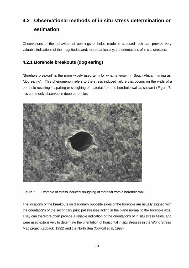
“Borehole breakout” is the more widely used term for what is known in South African mining as
“dog earing”. This phenomenon refers to the stress induced failure that occurs on the walls of a
borehole resulting in spalling or sloughing of material from the borehole wall as shown in Figure 7.
It is commonly observed in deep boreholes.
Figure 7 Example of stress induced sloughing of material from a borehole wall
The locations of the breakouts on diagonally opposite sides of the borehole are usually aligned with
the orientations of the secondary principal stresses acting in the plane normal to the borehole axis.
They can therefore often provide a reliable indication of the orientations of in situ stress fields, and
were used extensively to determine the orientation of horizontal in situ stresses in the World Stress
Map project (Zoback, 1992) and the North Sea (Cowgill et al, 1993).

20
Attempts have been made to use breakout data to estimate the magnitudes of in situ stresses (for
example Zoback et al, 1985; Zoback et al 1986; Lee and Haimson, 1993; Haimson and Song,
1993). In these attempts, the width and depth of the breakout have been measured as a basis for
estimating the stresses. Haimson and Herrick (1986) found that the depth and circumferential
extent of the completed breakout were directly proportional to the state of stress normal to the
borehole axis. Whilst this approach may have some potential for estimating indicative values of
stress, and relative or comparative values of stress, it is unlikely that it will be successful in the
adequate quantification of stress magnitudes in South African mines. This is due to the fact that
breakout mechanisms will be different for different types of rock, and extents of breakout will vary
depending on rock properties and in situ conditions (water, temperature, drilling, etc).
4.2.2 Core discing
Core discing appears to be closely associated with the formation of borehole breakouts. In brittle
rocks it has been observed that discing and breakouts usually occur over the corresponding
lengths of core and borehole. The thinner the discs the higher the stress level. However, the
formation of discs depends significantly on the properties of the rock and the magnitude of the
stress in the borehole axial direction (Stacey, 1982). In addition, the type and technique of drilling,
including the drill thrust, can significantly affect the occurrence of discing (Kutter, 1991). It is
therefore unlikely that observation and measurements of discing will be successful in quantifying
the magnitudes of in situ stresses. Nevertheless, the shape and symmetry of the discs can give a
good indication of in situ stress orientations (Dyke, 1989). If the discs are symmetrical about the
core axis, as shown in Figure 8, then it is probable that the hole has been drilled approximately
along the orientation of one of the principal stresses.
A measure of the inclination of a principal stress to the borehole axis can be gauged from the
relative asymmetry of the disc. For unequal stresses normal to the core axis, the core
circumference will peak and trough as shown in Figure 9. The direction defined by a line drawn
between the peaks of the disc surfaces facing in the original drilling direction indicates the
orientation of the minor secondary principal stress.

21
Figure 8 Core discs symmetrical with respect to the core axis
Drilling direction
Orientation of the minor secondary principal stress Disc peaks
Figure 9 Core discs resulting with unequal stresses normal to the core axis
If the discs are rather uniform in thickness as shown in Figure 8, the two secondary principal
stresses normal to the core axis will be approximately equal. Lack of symmetry of the discing, as
shown in Figure 10, indicates that there is a shear stress acting across the borehole axis and that
the axis is not in a principal stress direction.

22
Figure 10 Non-symmetrical core discing, indicating that the core axis is not a principal
stress direction
4.2.3 Observations of failures in excavations
Excavations can be considered as large boreholes, and observations of the behaviours of the walls
of the excavations in response to the in situ stresses can provide very valuable indications of the in
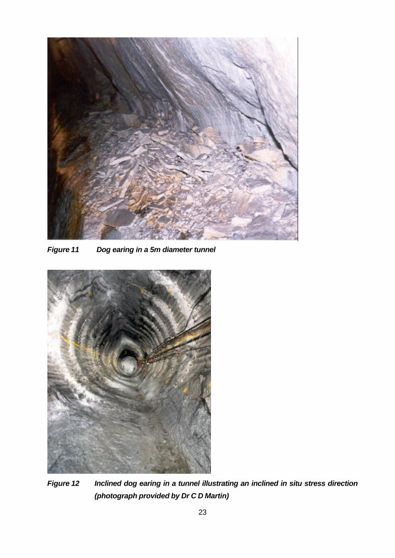
situ stress field. Dog earing in bored excavations can be equally pronounced as in boreholes.
Figure 11 shows a classic dog ear in the sidewall of a 5 m diameter tunnel. This shows that the
major secondary principal stress normal to the tunnel axis (i.e. the maximum stress in the plane
perpendicular to the tunnel axis) is vertical at this location.
Similarly, the dog earing in the tunnel in Figure 12 shows that the major secondary principal stress
is inclined at about 12o to the horizontal.
23
Figure 11 Dog earing in a 5m diameter tunnel
Figure 12 Inclined dog earing in a tunnel illustrating an inclined in situ stress direction
(photograph provided by Dr C D Martin)

24
In coal mining the use of stress mapping for the determination of horizontal stress directions has
been described by Mucho and Mark (1994). This approach is summarised in the following
paragraphs. Since it is simple, it involves no direct costs and is considered to have value with
regard to the provision of reliable in situ stress data.
Mucho and Mark (1994) identify the following set of principles with regard to horizontal stress:
a) the more closely the direction of drivage is aligned parallel to the major horizontal principal
stress direction, the less the ground damage;
b) ground damaged by horizontal stress, including caved or goaf areas, will stress relieve or
“shadow” adjacent ground, reducing or eliminating damage within this area;
c) when damage is immediate, occurring with mining or at least within a few hours of mining, the
first opening to encounter the stress field will suffer the most damage;
d) openings or retreat face lines create stress concentrations that can be the locations of
damage;
e) the direction of failure is in the direction of the minor horizontal principal stress;
f) where openings facilitate them, major failure features such as cutters and bottom (floor) heave
will usually align themselves perpendicular to the major horizontal principal stress. Roof
potting and shear failures will always exhibit this trend.
In the stress mapping approach, the following observations are made carefully:
• failure locations, orientations, geometry, type of failure, sequence of mining;
• shear planes, striations, rock flour, “freshness” of shear failures;
• offsets in blind bolt holes, tension cracks in the roof;
• roof potting, and relative lengths of major and minor axes in oval roof potting.
Mucho and Mark (1994) state that potting also gives an indication of the magnitude of the local
stress field. It is considered that this may be approximately true in local areas, particularly if some
form of calibration has been carried out. However, from an absolute point of view, the degree of
potting is unlikely to be a satisfactory indicator of stress magnitude. This is due to the fact that any
form of stress failure depends on the quality and brittleness of the rock and rock mass. Massive
brittle (but strong) rock may fail at much lower stress levels than a less massive, less brittle rock
mass. It has been observed that such failure can occur when the in situ stress level is as low as
10% of the UCS of the rock material (Stacey and Wesseloo, 1999).

25
An example of a generalised stress map with stress features and stress damage ratings is shown
in Figure 13.
1
1
1
1
1
1
1 1 1 1
1
1
1
1
1
1
1
1
1
1
1
1
1
1 1
1
6 5
3.5 3.5
2.5 2.5
2.5 2.5
N70E
N18W -N20W
-N22W
-N25W
Legend
T
Stress Mapping Symbols
- Cutter, guttering - Roof sag - Running roof failure - Roof fall
- Roof potting
- Shear plane, rock flour plane - Rib rash - Tension crack - Floor heave - Mapped principal stress direction
Stress Damage Rating
- Stable
- Slight cutter, after mining (<5cm) - Slight cutter, with mining (<5cm) - Deep cutter, after mining (>5cm) - Deep cutter, with mining (>5cm) - Severe potting, ½ roof effected - Severe potting, all roof effected - Heavy roof, obvious deformation - Roof fall
1
2
2.5
3
3.5
4
5
6
5.5
Roof Rating Profile Description
Figure 13 Example of stress mapping

26
4.3 Hydraulic fracturing methods
Hydraulic fracturing is now a well established method for determining in situ stress magnitudes. It
has been widely used in the oil well industry. Although hydraulic fracturing had been used
previously for other purposes such as borehole stimulation for increasing the yield of water supply
or dewatering boreholes, Scheidegger (1962) and Fairhurst (1964) were the first to suggest its use
for the determination of in situ stresses. Haimson (1968; 1977; 1983; 1993), Cornet (1993a),
Rummel (Rummel, 1987; Rummel et al, 1983) and Zoback (Zoback et al, 1977; Zoback et al,
1980; Zoback et al,1986) played a major role in developing and promoting the use of the hydraulic
fracturing technique. The method involves the pressurization of a length of borehole and the
measurement of the pressure required to fracture the rock or reopen existing fractures. Three
approaches will be dealt with in the following sections: conventional hydraulic fracturing in open
boreholes, hydraulic tests on pre-existing fractures (HTPF), and sleeve fracturing.
4.3.1 Hydraulic fracturing
Conventional hydraulic fracturing involves the pressurizing of a short length of borehole, isolated
using hydraulic packers on either side of it, until the hydraulic pressure causes the rock to fracture.
The characteristics of the pressure induced breakdown and the subsequent reopening of the
fracture under repressurisation are monitored carefully. The orientation of the induced fracture is
measured using a borehole television camera or a special impression packer to obtain a physical
record of the surface of the borehole. From all these data the orientations of the secondary
principal stresses normal to the axis of the borehole can be interpreted. Vertical boreholes are
usually used and it is assumed that the in situ principal stresses are vertical and horizontal.
The application of the method is illustrated diagrammatically in Figure 14.

27
Fracture Inflatable packer Compass
Rubber film
Impression packer
Fluid pressure Fluid pressure
a) b)
Figure 14 Hydraulic fracture application
The method requires special equipment, and associated services and personnel, to carry out a
measurement. The borehole must be diamond drilled or at least have a smooth bore. Since
packers are inserted in the borehole to seal off the test sections, the straightness and wall quality of
the borehole are important. A system for hydraulic fracturing stress measurements in deep
boreholes is illustrated in Figure 15. Although this represents the full sophistication of the method,
it is illustrative of the sort of requirements that would be necessary for quality measurements at
greenfields sites. A simpler set-up would be applicable for in mine tests.
After hydrofracturing, the borehole has to be inspected using a television camera, or a special
impression of its surface taken using an impression packer, to determine the orientation of the
induced fracture.

28
Figure 15 System for hydraulic fracturing stress measurements (after Tunbridge et al,
1989)

29
Figure 16 shows an idealised recording of a pressure versus time result for a hydraulic fracturing
test.
Time
Cycle 1 Cycle 2
P c = F r a c t u r e i n i t i a t i o n p r e s s u r e
P r = F r a c t u r e r e o p e n i n g p r e s s u r e
P s = S h u t- i n p r e s s u r e
P o = F o r m a t i o n p o r e
p r e s s u r e
P s = S h u t- in
p r e s s u r e
Shut in Shut in
Figure 16 Pressure vs. time record for hydraulic fracturing (after Enever et al, 1992)
In non-porous rocks, which are most likely to be encountered in mining in South Africa, the
minimum principal stress is given by the shut-in pressure. If a borehole is drilled in the vertical
direction, and it is assumed that this is a principal stress direction, and that the minimum principal
stress is horizontal, the major horizontal principal stress SH can be determined from the following
equation:
Hhc SSTP −⋅+= 3
Where T is the tensile strength of the rock
Sh is the minor horizontal principal stress
Pc is the fracture initiation pressure (Figure 16)
Interpretation of hydrofracture records can require expert input if the shut-in pressure is not distinct.
Interpretation of test results is not a straightforward activity, and the experience of the interpreter
has some effect on the in situ stress values ultimately determined. Different interpreters may
derive somewhat different results from the same set of field data. In porous rocks in particular,
30
interpretation of hydraulic fracturing tests may be very difficult and, owing to the pore pressure,
definition of the major principal stress may be doubtful. In sedimentary rocks, beds with a
thickness of at least 2 to 3m are necessary for satisfactory testing to be carried out.
Hydraulic fracturing stress measurements have been carried out at depths in the 6km to 9km range
(Amadei and Stephannson, 1997) and therefore the method is, in theory, suitable for the high
stress conditions encountered in deep level South African mines. At such high pressures, valves,
tubing and packers must be of special design to be able to perform as required. In boreholes in
which spalling or breakouts are occurring, there may be a risk of not being able to insert (or
recover) the packers, and it may also not be possible to seal off the borehole satisfactorily.
Borehole breakouts due to high stress levels may also interfere with the location of the fracture on
the borehole wall, and this may lead to inaccuracy in determining stress directions.
It is clear from the above that the application of the hydraulic fracturing method in South African
mines is theoretically possible, but would be expensive, and demanding on services. Perhaps the
most severe restriction, however, is the requirement that the borehole be drilled in the direction of
one of the principal stresses. In mining situations this is usually not known and is one of the in situ
stress parameters to be determined.
4.3.2 Hydraulic tests on pre-existing fractures (HTPF)
The HTPF method is a variation on conventional hydraulic fracturing. It consists of reopening an
existing fracture that had previously been identified in the borehole and isolated with packers. The
orientation of the fractures also needs to be measured. The pressure that just balances the normal
stress acting across the fracture is measured. By identifying at least six non-parallel pre-existing
fractures and carrying out hydraulic tests on such fractures, six components of in situ stress can be
determined, and hence the three dimensional in situ state of stress can be interpreted. The HTPF
method is the only hydraulic method where the borehole does not have to be assumed to be drilled
in a principal stress direction. It requires no assumptions regarding the in situ stress conditions or
the rock mass deformation and strength properties. It is also not necessary to determine the
tensile strength of the rock. The concept of the method is illustrated in Figure 17.

31
Joint
σn σn
Figure 17 Concept of HTPF method
Although there are many positives regarding the method, there are also negatives: fractures (joints)
must be well defined and uniform; there must be a sufficient number of joints, but not too many;
many tests are required and the stress field must be uniform in the area of these tests. The
method has been found to work well in homogeneous rock masses, but is not satisfactory in
stratified and heterogeneous rock masses (Burlet et al, 1989).
Application of the HTPF method requires a similar equipment set-up as for conventional hydraulic
fracturing.
4.3.3 Sleeve fracturing
Sleeve fracturing is similar to conventional fracturing except that the fluid is contained within a
rubber sleeve. Therefore, the fluid expands the sleeve, which in turn applies pressure to the walls
of the borehole causing a fracture to be induced in the rock. It appears that Stephannson (1983)
was the first to apply this method, although it is known that the concept was suggested in South
Africa in the early 1970’s by Leiding (1970).
The conventional application of sleeve fracturing is almost identical to that of hydraulic fracturing.
The sleeve is pressurized until a fracture is induced, with the pressure being monitored over time.

32
The pressure required for reopening of the fracture and the tensile strength of the rock can be used
to calculate the horizontal in situ stresses (assuming that the vertical borehole is drilled in a
principal stress direction). It is necessary to obtain an impression of the fracture formed to
determine the directions of the horizontal in situ stresses.
A more sophisticated sleeve fracturing method, that has been developed and tested significantly, is
that due to Serata et al (1992). In this approach, after the first fracture has been induced in a cycle
of loading, fracturing and unloading, the pressure is increased until a second fracture is induced.
This second fracture system usually occurs at right angles to the first fracture. During the testing,
the deformations of the borehole walls are measured by four diametral transducers as illustrated
diagrammatically in Figure 18.
Figure 18 Deformation measurement in sleeve double fracturing system (Serata et al,
1992)
From the plots of pressure vs. diametral deformations, the two reopening pressures corresponding
with the two fractures can be determined. Typical plots for reopening of the fractures are shown in
Figure 19.

33
Figure 19 Pressure vs. diametral deformation plots for sleeve double fracture testing
(Serata et al, 1992)
To calculate the in situ stresses, it is assumed that, at the time of reopening of each fracture, the
tangential stress at the borehole wall is zero at the fracture location. The following equations are
then applicable for a vertical borehole:
3Sh – SH – P1E = 0
3SH – Sh – P2E = 0
Solving for SH and Sh gives:
SH = (P1E + 3P2
E)/8
Sh = (P2E + 3P1
E)/8
Where SH is the major horizontal in situ stress
Sh is the minor horizontal in situ stress
P1E is the reopening pressure for the first fracture
P2E is the reopening pressure for the second fracture
The orientations of the fractures, and hence of the in situ stresses, can be determined from the
relative deformations measured by the four diametral transducers as shown in Figure 18. The
orientation of the deformation ellipse defines the directions of the two principal stresses. In this
method it is therefore not necessary to obtain an impression of the surface of the borehole wall to

34
determine the location of the fractures. The method itself provides both the in situ stress directions
and magnitudes.
Serata et al (1992) indicate that it is difficult to obtain sharp and consistent fracture initiation
breakdown points, that is, it is difficult to define these breakdown points on the pressure
deformation curves. There does not appear to be further published material on this method, and
therefore it is possible that the problem of breakdown point definition has not yet been overcome
satisfactorily.
In the most recent development of the sleeve fracturing system by Serata Geomechanics Inc
(2001), a single fracture system is used. Two special steel friction half cylinders are used to create
a single fracture at any desired orientation in the borehole, as shown diagrammatically in
Figure 20.
Figure 20 Single fracture stress measurement system (Serata Geomechanics Inc,
2001)
When the fracture planes are reopened, the in situ stress normal to the fracture plane is
determined from the curve of the pressure vs. the diametral deformation, as shown in Figure 21.

35
P
ress
ure
(MP
a)
Diametric Expansion (mm)
θE
B
N N PN
Figure 21 Pressure-deformation curves for single fracture system
The in situ stress normal to the fracture óN is determined from the reopening pressure PN and the
rock stiffness, determined from the pressure-deformation curve:
óN = n·PN
Where n = a(tan èE)b
èE is defined on the pressure-deformation curve in Figure 21
a and b are design factors for the instrument
Since the single fracture can be created at any desired angle, the method can be used to
determine the three dimensional state of stress, making use of at least three boreholes with
different orientations. The deformation modulus of the rock in each test direction is determined
automatically as part of the test. It is claimed that 20 to 30 single fracture measurements can be
made per day.
The application of Serata Geomechanics Inc (2001) method in its current format requires a smooth
borehole (diamond drilled or reamed). This implies that quality drilling equipment with the capacity
to drill these holes would be required. The further implication of these requirements is that the
application of this method of in situ stress measurement would require the provision of such drilling
equipment as well as the provision of compressed air and water services. The instrument will not
work satisfactorily in a hole that is not smooth and circular. This implies that if any spalling/dog
earing has occurred in the borehole, it will not be suitable for use with this system.

36
As with the conventional hydraulic fracturing system, the magnitude of in situ stresses that can be
measured is dictated by the pressure capacity of the equipment. The maximum stress that can be
measured by the Serata Geomechanics Inc system (2001) is 40 MPa (Serata Geomechanics,
2001). This is not a high magnitude in the context of deep level gold mining, and hence the
method will require further development for application in such high stress conditions. Although the
system appears to be attractive for use in lower stress mining environments, it is a concern that it
appears to be “proprietary” – apart from the publications of Serata, there do not appear to be any
independent publications or reports that would provide independent confirmation of satisfaction
with the method. From the mining point of view, a detraction is the requirement for special
boreholes.
4.4 Interpretation of stress “memory” in the rock
Rock, in situ, tends to develop a “memory” of the stress field under which it has been confined (for
example, Kurita and Fujii, 1979; Charlez et al, 1986). A sample of this rock removed from this
confining environment will react to its unloading and subsequent reloading, and the strains
measured have been found to be representative of the original confining stress field. Acoustic
emissions that occur on reloading of the rock are also representative of the original stresses and
can be used to determine the in situ stress field.
Various methods that deal with stress history will be dealt with in this section. These methods are
potentially very attractive with respect to determination of in situ stresses in South African mines.
They make use of rock cores obtained remotely, with subsequent sample preparation and strain or
other measurements being made under controlled conditions in the laboratory. Such methods
therefore have potential application to both greenfields sites and to well established mining
operations, and have the potential of being very cost effective.
4.4.1 Anelastic strain recovery methods
In the anelastic strain recovery (ASR) method, an oriented core sample is instrumented to monitor
the strain changes with time, as the core relaxes or recovers from its former state of stress. Strains
are measured in the laboratory on orientated cores or cubical samples. Interpretation of in situ
stress directions can be made directly from the strain measurements. However, the determination
of stress magnitudes is much more difficult, and requires a constitutive viscoelastic model for strain
relaxation.

37
The method has been used successfully for determining in situ stress directions and ratios (Teufel,
1982). Results for stress directions have also shown good agreement with those of other methods
such as hydraulic fracturing and observation of borehole breakouts (Warpinski and Teufel, 1989;
Perreau et al, 1989). Matsuki and Sakaguchi (1995) used the technique and applied the theory
developed by Matsuki (1991) and Matsuki and Takeuchi (1993). They found that the results were
in poor agreement with those from an overcoring method.
There are numerous factors that can affect ASR methods (Amadei and Stephannson, 1997). The
main factors are:
• Temperature variations that can result in thermal strains;
• Changes in moisture content and pore pressures in the rock sample;
• Non-homogeneous recovery of deformations;
• Anisotropy of the rock;
• Interaction between the rock and the drilling mud or water, including degrading of the rock;
• Residual strains;
• Core recovery time;
• Errors in core orientation.
Based on these sources of error, the fact that a viscoelastic constitutive model for strain relaxation
must be assumed for the determination of stress magnitudes, and the rather limited use that has
been made of the ASR method, it is unlikely that it will be a satisfactory method at this stage for
application in South African mines.
4.4.2 Differential strain curve analysis
The differential strain curve analysis (DSCA) method involves cutting a cubical sample out of an
oriented drill core, attaching strain gauges to its surface and then applying hydrostatic loading to
the sample. The method is based on the following assumptions:
• When a rock sample is taken from a location subjected to a significant in situ stress field,
the rock material will microcrack in proportion to the pre-existing effective state of stress;
• The directions of the original stress field determine the alignment of the cracks;
• In any direction there is a volumetric relationship between the cracks and the in situ stress
magnitude in that direction;

38
• Under the hydrostatic loading, the contraction strain which takes place in a particular
direction in the rock sample are analogous to the original strain in that direction.
The strain gauges measure the response of the cubical sample. If a minimum of 6 gauges,
measuring 6 independent strains, is used, then the three principal strains due to crack closure can
be determined. These strains are then related to the in situ stresses. Usually 9 or 12 strain
gauges would be attached to the cubical sample. Orientations for 12 gauges are shown in
Figure 22. Also shown in Figure 22 is the type of confining pressure vs. longitudinal strain curve
that would be obtained for each gauge direction.
z
y
x
Longitudinal strain
Con
finin
g pr
essu
re
Crack closure
a) b)
Figure 22 Strain gauge orientations and typical pressure vs. strain relationship for
DSCA
The DSCA is a development of the differential strain analysis, a laboratory technique to
characterise the porosity of micro cracks in rock samples at various pressures. This technique was
modified by Strickland and Ren (1980) to enable it to be used to predict in situ stresses, and they
used it for this purpose. Ren and Roegiers (1983) developed the method further and concluded
that it was a cost effective technique that did not require any assumption regarding the orientation
of the in situ stress field with respect to the borehole orientation.
DSCA in situ stress measurements carried out by Dey and Brown (1986) gave reasonable
magnitudes and directions. Perreau et al (1989) found good agreement between horizontal stress

39
orientations obtained from DSCA and other methods. Matsuki and Sakaguchi (1995) did not have
success in determining the absolute in situ state of stress using DSCA. Figure 23 shows a set of
results obtained by Oikawa et al (1993). The scatter in these results would be unacceptable for
use in the South African mining environment.
E W
N
S LOWER HEMISPHERE
Maximum Intermediate Minimum
Figure 23 Example of in situ stress directions determined using DSCA (after Oikawa
et al, 1993)
Although the method appears to have potential, it does not appear to have been used significantly
for in situ stress determination. According to Ren and Roegiers (1983), the quality and reliability of
DSCA results depend strongly on experience. Based on this and its limited use, it is unlikely that
DSCA is a method that would be suitable at this stage for routine use in South African mines.
4.4.3 Kaiser effect method
Kaiser (1953) observed that when the stress on a polycrystallised metal was relaxed and then
reapplied, there was a significant increase in the rate of acoustic emission when the previous
maximum stress level was exceeded. This phenomenon has become known as the Kaiser effect.
Goodman (1963) observed a similar effect in rocks. It appears that Kanagawa et al (1976) were
the first to make use of the phenomenon to estimate in situ stresses, and Hayashi et al (1979) were
also early users. A considerable amount of further development of the method has taken place.
Hughson and Crawford (1986) demonstrated experimentally that, from a sample of rock extracted

40
from a stressed environment, it was possible to determine the magnitude of the maximum stress to
which the rock had been subjected, as well as how much more stress it could withstand before
becoming unstable.
The Kaiser effect method involves the drilling of small secondary, orientated cores from the original
core removed from the stressed environment. The original core must be orientated so the
directions of secondary coring are known in relation to this original core orientation. The secondary
cores are prepared with the required end flatness and parallelism, and then subjected to uniaxial
compressive stress whilst the acoustic emissions from the rock are monitored using sensors
attached to the core. On a plot of the applied stress vs. the acoustic emissions, the Kaiser effect
change point is at the position on the curve where the slope of the plot noticeably increases. As
the Kaiser effect changes in acoustic emission rate, the stress corresponds with the previous
maximum stress to which the rock had been subjected. If a sufficient number of secondary cores
are tested, the full three dimensional in situ state of stress may be determined. Hughson and
Crawford (1986) noted that:
• The Kaiser effect does not occur abruptly at a precisely definable point, but within a
transitional zone;
• The position and abruptness of this zone varies for different types of rock materials, and
with the magnitude of the previous stress relative to the strength of the rock (Hughson and
Crawford refer to the Stability Limited Stress of the material);
• The transition zone becomes large and indistinct if the maximum stress exposure time was
brief.
The stress “memory” reduces over time, and hence it is necessary to carry out the tests within a
relatively short time after removal of the original core. The length of the “memory” appears to
depend on the type of rock (Hughson and Crawford, 1986). Kurita and Fujii (1979) conclude that
no significant recovery of the Kaiser effect occurs within one month of removal from the stressed
environment. Friedel and Thill (1990) found that the effect was retained for a period of up to at
least 5 months. Other researchers have noted very much shorter retention periods, for example,
several hours (Goodman, 1963), one to five days (Yoshikawa and Mogi (1981), three days (Boyce,
1981). These limitations are contradicted by the results of Seto et al (1998), who obtained
satisfactory results for in situ stress determinations on cores that had been removed almost two
years previously. Their results agreed to within 10% of values determined by other methods and
by estimation of overburden stress.

41
Hughson and Crawford (1987) and Holcomb (1993) indicate that the position of the Kaiser effect
change is dependent on the confining stress, that is, it depends on the three dimensional state of
stress. Holcomb argues, therefore, that the stress determined for the Kaiser effect change point
using uniaxial loading will be in error and that the original state of stress cannot be uniquely
determined. This is perhaps logical since the strain state depends on the three dimensional state
of stress.
Momayez and Hassani (1992) refer to a technique called the “maximum curvature method” that
determines the exact location of the Kaiser effect point by calculating the curvature at every point
along the stress-acoustic emission curve. The maximum value for the curvature corresponds with
the point where the change in the slope of the stress-acoustic emission occurs.
Hughson and Crawford (1988) indicate also that the Kaiser effect does not necessarily occur
precisely at the previous maximum stress level – it overestimates the maxima that are low relative
to the strength of the rock and underestimates the maxima that are high. They refer to a Felicity
factor, which is the ratio of the Kaiser effect stress to the previous maximum stress.
Recent use of the Kaiser effect method for in situ stress determination in mines in Australia (Seto
et al, 1998; Villaescusa et al, 2000; Seto et al, 2000; Villaescusa, 2001) demonstrate that none of
these apparent limitations are significant. There appear to have been no problems with the
determination of the Kaiser effect change point (it does not appear that they make use of the
maximum curvature method), with the effect of confining stress, and there is also no mention of the
application of a Felicity factor. In the testing, in situ stress results were determined with acceptable
accuracy, and compared well with results obtained from other in situ stress measurement methods.
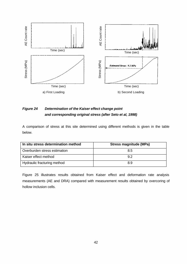
As an example of the application of the method, Figure 24 shows a plot of the applied uniaxial
stress against the acoustic emission behaviour for a rock core, removed two years previously from
a depth of 356m.
42
Time (sec)
AE
Co
un
t ra
te
AE
Co
un
t ra
te
Time (sec)
Time (sec) Time (sec)
Str
ess
(MP
a)
a) First Loading b) Second Loading
Str
ess
(MP
a)
Figure 24 Determination of the Kaiser effect change point
and corresponding original stress (after Seto et al, 1998)
A comparison of stress at this site determined using different methods is given in the table
below.
In situ stress determination method Stress magnitude (MPa)
Overburden stress estimation 8.5
Kaiser effect method 9.2
Hydraulic fracturing method 8.9
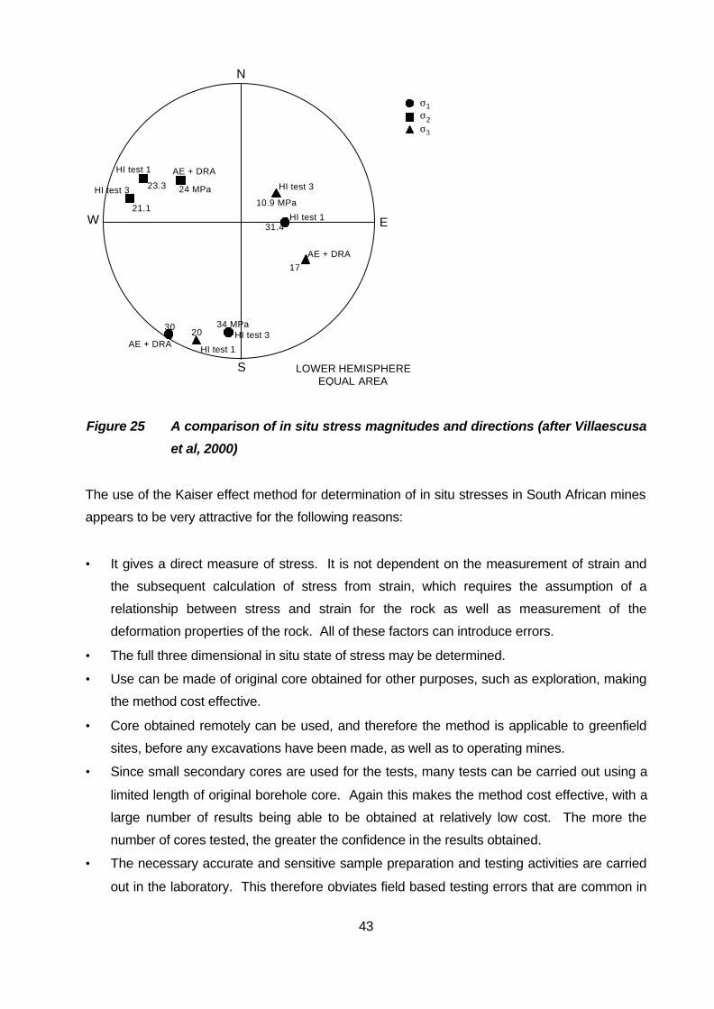
Figure 25 illustrates results obtained from Kaiser effect and deformation rate analysis
measurements (AE and DRA) compared with measurement results obtained by overcoring of
hollow inclusion cells.
43
E W
N
S LOWER HEMISPHERE EQUAL AREA
σ1 σ2 σ3
HI test 1
HI test 3
HI test 3
HI test 1
AE + DRA
AE + DRA
HI test 3
HI test 1
23.3
21.1 10.9 MPa
31.4
17
24 MPa
34 MPa 20
AE + DRA
30
Figure 25 A comparison of in situ stress magnitudes and directions (after Villaescusa
et al, 2000)
The use of the Kaiser effect method for determination of in situ stresses in South African mines
appears to be very attractive for the following reasons:
• It gives a direct measure of stress. It is not dependent on the measurement of strain and
the subsequent calculation of stress from strain, which requires the assumption of a
relationship between stress and strain for the rock as well as measurement of the
deformation properties of the rock. All of these factors can introduce errors.
• The full three dimensional in situ state of stress may be determined.
• Use can be made of original core obtained for other purposes, such as exploration, making
the method cost effective.
• Core obtained remotely can be used, and therefore the method is applicable to greenfield
sites, before any excavations have been made, as well as to operating mines.
• Since small secondary cores are used for the tests, many tests can be carried out using a
limited length of original borehole core. Again this makes the method cost effective, with a
large number of results being able to be obtained at relatively low cost. The more the
number of cores tested, the greater the confidence in the results obtained.
• The necessary accurate and sensitive sample preparation and testing activities are carried
out in the laboratory. This therefore obviates field based testing errors that are common in
44
the often harsh mining environment. Interference with production mining operations is also
reduced or eliminated.
At this stage it is not known what effect fracturing of core, induced during the drilling process,
will have on the application of the method. Applications to date in a mining environment have
been at relatively shallow depth, and therefore generally at stress levels well below the strength
of the rock. It is therefore possible that application in the deep level gold mines may be
problematic. However, stress magnitudes of close to 100 MPa have been determined in mine
pillars in Australia (Villaescusa, 2001), and this indicates optimism for the use of the method at
high stress levels.
The success of the AE method for in situ stress determination in mines has recently been
confirmed at more than 10 mine sites in Australia, involving numerous measurements (Potvin,
2002). These results represent measurements in both igneous and sedimentary rock types.
4.4.4 Deformation rate analysis
The deformation rate analysis method (DRA) also makes use of the “memory” effect. However,
instead of the acoustic emission being monitored, the strain in the cores is measured by means
of strain gauges bonded to the core as the uniaxial stress on the core is increased. The
concept of the method is that there is a change in the stress-strain relationship of the rock when
the point or previous maximum stress is encountered. The original stress can be determined
from the change in gradient of the stress-strain curve under cyclic uniaxial compression tests.
As indicated by Seto et al (1998) and Villaescusa et al (2000), the gradient changes are
determined from cyclic loading tests, with the strain difference values between two cycles being
measured as a function of the applied stress:
Äå j = å j(ó) - åi(ó); j>i
Where å j is the strain measured in the jth loading cycle, and
ó is the applied stress corresponding with that strain.
This strain difference function represents mainly the inelastic strain difference between the two
cycles. The reversible or elastic components of strain are cancelled by the operation in the
above equation. Using the strain difference function, the point of gradient change of the applied
stress-strain curve can be detected and hence the value of the original normal stress in the
direction of the core axis determined.

45
Since the core sample preparation and loading activities involved in the DRA method are the
same as those required for the Kaiser effect method, it is logical to apply both methods at the
same time to determine the in situ state of stress. The simultaneous use of the two methods on
the same core lends greater confidence to the in situ stress results obtained.
Villaescusa et al (2000) combined the results from Kaiser effect and DRA methods as shown in
Figure 25.
The advantages identified above for the application of the Kaiser effect method in South African
mines are equally applicable for the DRA method.
4.5 Geophysical methods
There is a relationship between the passage of seismic waves in a rock mass and the in situ
state of stress in the rock mass (Swolfs and Handin, 1976; Isobe et al, 1976). The use of this to
estimate the directions and magnitudes of in situ stresses does not appear to have been
pursued, however.
Interpretation of earthquake data to obtain fault plane solutions, which give the directions of the
horizontal in situ stresses, has been widely used. It is the basis of much of the data contained
in the World Stress Map (Zoback, 1992; Anon, 1997). The method is a valuable source of in
situ stress information, but does not allow determinations of in situ stress at particular locations,
nor does it provide stress magnitudes. Hence, it is not generally applicable to South African
mining conditions.
4.6 Back analysis of excavation deformations
When an excavation is made, or an excavation enlarged, in a rock mass, displacements around
the excavation occur in response to the action of the in situ stresses. The relationship between
the displacements and the stresses can be represented by a simple equation:
{u} = [F]{ó}
where {u} is a matrix of displacements
{ó} is a matrix of the in situ stresses

46
[F] is the flexibility matrix, which is a function of the deformation properties of the rock
and the geometry and dimensions of the excavation
If the displacements can be measured, then the in situ stresses can be calculated (back
analysed) by rearranging the equation:
{ó} = ([F]T[F])-1[F]T{um}
where {um} is the matrix of measured displacements.
For solution of the equation, it is necessary to make use of a numerical stress analysis
technique such as the boundary element or finite element methods. The back analysis method
has been dealt with in detail by Akutagawa (1991). Although Sakurai and Akutagawa (1994)
have extended the methodology to account for non-elastic rock behaviour, from a practical point
of view the calculation of in situ stresses requires linearly elastic rock deformation behaviour. If
a sufficient number of independent deformation measurements is available, the full three
dimensional in situ state of stress may be determined. The assumption of linearly elastic
behaviour is likely to be restrictive in many cases and in particular at deep level where the rock
surrounding an opening is likely to be fractured and in a state of failure.
In the use of a back analysis technique, the larger the excavation involved, the larger the
volume of rock that will be affected. The benefits of such an approach compared with other
methods of in situ stress measurement have been outlined by Wiles and Kaiser (1994a).
Examples of the use of the back analysis method have been published by, for example, Kaiser
et al, 1990; Sakurai, 1988; Sakurai and Shimizu, 1986.
In mining operations, openings are often created in close proximity such that the excavation of
the second opening will cause deformations of the first opening. Also, as tunnels are advanced,
the perimeter of the tunnel close behind the face deforms as a result of the excavation (Wiles
and Kaiser, 1994a and 1994b). These excavation induced deformations can be measured and
related to the in situ stresses acting in the rock mass.
The application of the method is limited to the availability of sites at which excavation enlargements
are being made (unless enlargements are made specifically for the purposes of in situ stress
measurement) or adjacent openings are being excavated. This could have a large interference
factor on mining operations. The dependence on openings being created means that the method
is not applicable to greenfields sites. In addition, sophisticated instrumentation is usually required,
47
with associated special borehole drilling, and this implies significant cost as well as further
interference. The reliability and survivability of instrumentation in South African mines is known to
be a serious problem, particularly if it is required to be effective over a significant period of time.
For the above reasons, back analysis is not an attractive method for general application in
South African mining. However, it is considered to be a valuable method that can be applied on
an ad hoc basis whenever a suitable opportunity arises.
5 Ranking of non strain gauge based methods of in
situ stress measurement
Based on the review of alternative methods of in situ stress measurement above, those
methods that are considered to have significant potential application to South African mining are
dealt with in the perceived order of significance in the following sections.
5.1 Estimation of in situ stresses
Estimation of in situ stresses is given the highest ranking, since it is considered that it should
always be the first approach applied to obtain an indication of the in situ stress directions and
magnitudes. The following activities are suggested in the recommended order of application:
• reference to the Southern African database of in situ stress information. This will provide
an indication of likely stress directions and horizontal to vertical stress ratios in the area. It
should be assumed that the vertical stress is due to the overburden pressure;
• observation and interpretation of core discing, if any, in borehole core. This may give some
indication of stress directions and possibly stress magnitudes;
• if geophysical type logging of boreholes has been carried out, calliper logs of the borehole
may show up breakouts (dog ears), which will provide a very positive indication of stress
directions;
• if underground excavations are available for inspection, observation of stress induced
fracturing will give valuable indications of stress orientations and relative stress magnitudes.
Routine application of the stress mapping technique, and subsequent interpretation of
these mapping data, are recommended.

48
Estimation of in situ stresses is ranked highest of the methods for the following reasons:
• it involves no direct costs, simply an investment in time;
• it requires the rock engineering and geological personnel, who would be responsible for the
estimations, to think carefully about the mining situation when interpreting the available
information. This will have safety related benefits;
• it requires these personnel to inspect and investigate aspects that they would possibly not
do otherwise, and again this will have safety related benefits;
• perhaps most importantly, these personnel on the mine will “own” their own design and
analysis data, and it will be their responsibility rather than the responsibility of some
“remote” organisation to provide them with the data.
Estimation and observation should be carried out even if the in situ stress is to be measured by
other methods. It is important to realize that although this method is very powerful in developing
an understanding of the stress state in the mining area, it is based on subjective interpretation
and judgment, making it a very dangerous method if used in isolation. This method should
therefore be used routinely, to develop an understanding of the stress state but should be
complemented by data obtained from other methods.
5.2 Kaiser effect gauging using acoustic emission
The Kaiser effect technique to determine in situ stresses in South African mining situations is
ranked second in order of significance for the following reasons:
• it is applicable to both local and remote situations, and therefore applicable to both existing
mining operations and greenfield sites;
• it is applicable to both shallow and deep mining operations. The method has been used to
determine stresses at depths of about 200 m and at a magnitude of 100 MPa;
• it can make use of borehole core retrieved for other purposes such as exploration. Testing
can be carried out on non-ore core, so that there is no interference with exploration
activities. A requirement is that the core is orientated, and this represents no problem since
it is a standard operation in diamond drilling;
• it is possible to make use of “old” core (possibly one to two years, depending on rock type)
provided that the orientation of the core is known. This should be easily feasible in
sedimentary deposits in which the dip of the stratification defines the orientation;
• no measurements are made on site, hence there is no interference with mining production
operations, nor requirement for special services;

49
• all accurate sample preparation and testing activities are carried out in a laboratory under
controlled conditions, therefore limiting any experimental errors;
• sample preparation and testing make use of conventional equipment;
• since small secondary core samples are used, it is possible to carry out a large number of
tests on a small amount of borehole core in a short period of time. The implication is that
the cost of in situ stress measurements using this method is relatively low;
• the method gives a direct measure of stress, unlike most of the methods of in situ stress
measurement in current use that measure strain changes;
• the method yields the full three dimensional in situ state of stress from tests on core from a
single borehole. It is not necessary to have boreholes specially drilled in several directions.
A few years ago, when a review of in situ stress measurement methods was carried out
(Stacey, 1995), this method was not considered seriously. Its practical effectiveness had not
been demonstrated at that time. This situation has changed recently, however, as a result of
the following:
• the method has recently been successfully applied to determine stresses in coal mines in
Australia;
• a research project has been in progress in Australia for several years in which the method
is being applied at numerous mines;
• results obtained recently in mining applications have been encouraging, providing
significant confidence in the method.
The fact that the method is already being applied successfully in mining situations implies that it
has now possibly establishing itself as an accepted method of routine in situ stress
measurement.
The measurement of the Kaiser effect change point using acoustic emission appears to be the
most satisfactory approach and it is this approach that is recommended. However, it is little
extra effort to measure the strains in the sample at the same time, and therefore the concurrent
use of the deformation rate analysis method to provide additional confidence in the
determination of the Kaiser effect change point should be considered.
Some research and development will be necessary to learn the techniques and gain sufficient
experience to establish the method as a routine method for in situ stress measurement in South
Africa.

50
5.3 Sleeve fracturing
Conventional hydraulic fracturing is a well established method of in situ stress measurement,
particularly in the oil well industry. It has an advantage that it yields directly the magnitude of
the minor principal stress in a plane normal to the borehole axis. However, it has several
disadvantages, the most significant of which are considered to be:
• the requirement that the borehole is drilled in a principal stress direction;
• clear determination of the major principal stress in the plane normal to the borehole axis is
affected by the pore pressure in the rock.
Owing to these drawbacks it is not considered suitable for routine stress measurements in
mines. Hydraulic testing of pre-existing fractures (HTPF) overcomes these problems. However,
HTPF requires a large number of tests and therefore is also not considered suitable for routine
application in mines.
Sleeve fracturing as developed by Serata Geomechanics Inc, however, appears to be much
more suited to routine applications, for the following reasons:
• 20 to 30 tests can be carried out in a day;
• the fracture can be induced in the borehole at any desired direction. There is no
requirement therefore to determine the fracture orientation using an impression packer;
• from the method the value of in situ stress normal to the direction of the induced fracture
can be calculated easily from the test results.
The method is not given a higher ranking for the following reasons:
• smooth boreholes with a diameter of reasonably close tolerance are required. Tests cannot
be carried out where the walls of the borehole are irregular, such as where spalling and
breakouts occur;
• tests in three boreholes drilled at different orientations are required to determine the full
three dimensional in situ state of stress;
• test equipment is specialised and appears to be proprietary, implying that stress
measurements made with the method would probably be costly;
• the requirement for special smooth boreholes implies that special services would be
required and that there would probably be interference with production operations;

51
• the method is not applicable to greenfield sites, and is limited at present to the
measurement of a maximum in situ stress of 40 MPa.
5.4 Back analysis of measured deformations
The back analysis of in situ stresses using deformations measured around excavations as a
result of changes in the geometry of that or adjacent excavations is not rated as a routine
method of determining in situ stresses. However, the approach is valuable since a large volume
of rock is involved. Therefore, if the opportunity arises with suitable deformation measurements
being available, the approach is ranked as a method that should be used. The in situ stress
results, based on the deformation of a large volume of rock, will be valuable for comparison with
the stresses obtained from other methods.
6 Conclusions and recommendations
It is concluded that the most suitable “new” method of in situ stress measurement is the use of
Kaiser effect gauging, with the Kaiser effect change point being determined by means of
acoustic emission monitoring. It is recommended that some research and development of the
method should be funded to gain the necessary familiarity and experience with its application to
make it a routine method of in situ stress measurement in South Africa.
Stress estimation using the existing in situ stress database and observations of rock behaviour
around openings should be practised in addition to any measurement of stresses. Routine
stress mapping by rock engineering and geological personnel will provide additional on-going
valuable information, and will be of benefit to safety. It is recommended that the development of
a stress mapping and interpretation system for South African mines should also be funded.
Such a system will provide the industry with a standardised method for mapping and
interpreting the fracture behaviour of the rock mass in relation to the in situ stress field, and will
aid communication on the subject.
Back analysis of stresses is valuable in that it involves a large volume of rock, and should be
carried out as and when suitable deformation monitoring data are available.

52
References and bibliography
ADDIS, M A and WU, B (1993) The role of the intermediate principal stress in wellbore stability
studies: evidence from hollow cylinder tests, Int. J. Rock Mech. Min. Sci., Vol 30, No 7, pp1027-
1030.
AKUTAGAWA, S (1991) A back analysis system for geomechanics applications, PhD Thesis,
University of Queensland, 325p.
ALTOUNYAN, P and TALJAARD, D (2001) Developments in controlling the roof in South
African coal mines – a smarter approach, Jl S. Afr. Inst. Min. Metall., Vol 101, No 1, pp 33-40.
AMADEI, B and STEPHANNSON, O (1997) Rock Stress and its Measurement, Chapman &
Hall, 490p.
ANON (1997) World Stress Map, Internet Website,
http://www.gpi.physik.unikarlsruhe.de/pub/wsm/index.html
BARLA, G, BERTACCHI, P, ZANINETTI, ROSSI, P P and VIELMO, I (1986) Hydraulic
fracturing testing method for rock stress measurements in Italy, Proc. Int. Symp. Rock Stress
and Rock Stress Measurements, Stockholm, Centek Publishers, pp 331-340.
BOCK, H (1986) In-situ validation of the bore hole slotting stressmeter, Proc. Int. Symp. Rock
Stress and Rock Stress Measurements, Stockholm, Centek Publishers, pp 261-269.
BOCK, H and FORURIA, V (1983) A recoverable borehole slotting instrument for in situ stress
measurements in rocks not requiring overcoring, Int. Symp. on Field Measurements in
Geomechanics, Zurich, Balkema, pp 15-29.
BONNECHERE, F J and CORNET, F H (1977) In situ stress measurements with a borehole
deformation cell, Proc. Int. Symp. on Field Measurements in Geomechanics, Zurich, Balkema,
Vol 1, pp 151-159.
BOONE, T J, INGRAFFEA, A R and ROEGIERS, J-C (1991) Simulation of hydraulic fracture
propagation in poroelastic rock with application to stress measurement techniques, Int. J. Rock
Mech. Min. Sci. & Geomech. Abstr., Vol 28, No 1, pp 1-14.

53
BOWLING, A J (1976) Surface rock stress measurement with a new cylindrical jack, Proc.
Symp. Investigation of Stress in Rock, Int. Soc. Rock Mech. Symp., Sydney, pp 7-11.
BRADY, B H B, FRIDAY, R G and ALEXANDER, L G (1976) Stress measurement in a bored
raise at the Mount Isa Mine, Proc. Symp. Investigation of Stress in Rock, Int. Soc. Rock Mech.
Symp., Sydney, pp 12-16.
BOYCE, G L (1981) A study of the acoustic emission response of various rock types, Master of
Science dissertation, Drexel University (quoted as reference by Momayez and Hassani, 1992)
BRUDY, M and ZOBACK, M D (1999) Drilling-induced tensile wall-fractures: implications for
determination of in-situ stress orientation and magnitude, Int. J. Rock Mech. Min. Sci., Vol 36,
pp 191-215.
BURLET, D, CORNET, F H and FEUGA, B (1989) Evaluation of the HTPF method of stress
determination in two kinds of rock, Int. J. Rock Mech. Min. Sci. & Geomech. Abstr., Vol 26, pp
673-679.
BUTTERWORTH, S and BURTON, P W (1993) Variability and quality in ASR data represented
by the Sandia model, Int. J. Rock Mech. Min. Sci., Vol 30, No 7, pp 1009-1012.
CHANDLER, N A (1993) Bored raise overcoring for in situ stress determination at the
Underground Research Laboratory, Int. J. Rock Mech. Min. Sci., Vol 30, No 7, pp 989-992.
CHARLEZ, Ph, HAMAMDJIAN, C and DESPAX, D (1986) Is microcracking of a rock a memory
of its initial state of stress? Proc. Int. Symp. Rock Stress and Rock Stress Measurements,
Stockholm, Centek Publishers, pp 341-350.
CHARLEZ, Ph, SALEH, K, DESPAX, D and JULIEN, Ph (1986) A new way to determine the
state of stress and the elastic characteristics of rock massive, Proc. Int. Symp. Rock Stress and
Rock Stress Measurements, Stockholm, Centek Publishers, pp 313-322.
CHEATHAM, J B Jr (1993) A new hypothesis to explain stability of borehole breakouts, Int. J.
Rock Mech. Min. Sci., Vol 30, No 7, pp1095-1011.

54
COOLING, C M, HUDSON, J A and TUNBRIDGE, L W (1988) In situ rock stresses and their
measurement in the U.K. – Part II. Site experiments and stress field interpretation, Int. J. Rock.
Mech. Min. Sci. & Geomech. Abstr., Vol 25, No 6, pp 371-382.
CORNET, F H (1986) Stress determination from hydraulic tests on pre-existing fractures – the
H.T.P.F. method, Proc. Int. Symp. Rock Stress and Rock Stress Measurements, Stockholm,
Centek Publishers, pp 301-312.
CORNET, F H (1993a) Stresses in rock and rock masses, in Comprehensive Rock
Engineering, ed J A Hudson, Pergamon Press, Oxford, pp 297-327.
CORNET, F H (1993b) The HTPF and the integrated stress determination methods, in
Comprehensive Rock Engineering, ed J A Hudson, Pergamon Press, Oxford, pp 413-432.
CORTHESY, R, GUANG He, GILL, D E and LEITE, M H (1999) A stress calculation model for
the 3D borehole slotter, Int. J. Rock Mech. Min. Sci., Vol 36, pp493-508.
COSTIN, L S (1983) A microcrack model for the deformation and failure of brittle rock, J.
Geophys. Res., Vol 88, No B11, pp 9485-9492.
COWGILL, S M, MEREDITH, P G, MURRELL, S A F and BRERETON, N R (1993) Crustal
stresses in the North Sea from breakouts and other borehole data, Int. J. Rock Mech. Min. Sci.,
Vol 30, No 7, pp1111-1114.
DEY, T N and BROWN, D W (1986) Stress measurements in a deep granitic rock mass using
hydraulic fracturing and differential strain curve analysis, Proc. Int. Symp. Rock Stress and Rock
Stress Measurements, Stockholm, Centek Publishers, pp 351-357.
DICKIE, D E and SERATA, S (1993) Long term evaluation of stress control method of
underground mining at Sifto Salt Mine, Mining Engineering, January 1993,
DU, Y and AYDIN, A (1992) The role of compression-induced tension in propagation of
hydrofractures: implications for in situ stress measurements at shallow depths, Int. J. Rock
Mech. Min. Sci. & Geomech. Abstr., Vol 29, pp 589-593.

55
DU, W and KEMENY, J M (1993) Modelling borehole breakout by mixed mode crack growth,
interaction, and coalescence, Int. J. Rock Mech. Min. Sci. & Geomech. Abstr., Vol 30, No 7, pp
809-812.
DUGAN, K J, HULLS, I H and MILLER, D R (1993) Recent experiences with the borehole
slotter for measuring in-situ stress, Geotechnical Instrumentation and Monitoring in Open Pit
and Underground Mining, Balkema, pp 117-124.
DYKE, C G (1989) Core discing: its potential as an indicator of principal in situ stress
directions, Rock at Great depth, ed Maury & Fourmaintraux, Balkema, pp 1057-1064.
ENEVER, J and McKAY, J (1976) A note on the relationship between anelastic strain recovery
and virgin rock stresses – a possible method of stress measurement, Proc. Symp. Investigation
of Stress in Rock, Int. Soc. Rock Mech. Symp., Sydney, pp 37-40.
ENEVER, J R, CORNET, F and ROEGIERS, J C (1992) International Society for Rock
Mechanics, Commission on Interpretation of Hydraulic Fracture Records, Int. J. Rock Mech.
Min. Sci. & Geomech. Abstr., Vol 29, No 1, pp 69-72.
FAIRHURST, C (1964) Measurement of in situ rock stresses with particular reference to
hydraulic fracturing, Rock Mech. & Engng Geol., Vol 2, pp 129-147.
FALMAGNE, V (1991) Rock mechanics and microseismic monitoring at Ansil, CIM Bull., Vol
84, No 955, December 1991, pp 46-51.
FRIEDEL, M J and THILL, R E (1990) Stress determination in rock using the Kaiser effect,
Report of Investigations, US Dept of the Interior, Bureau of Mines, No 9286, 20p.
GOODMAN, R E (1963) Subaudible noise during compression of rocks, Geol. Soc. Am. Bull.,
Vol 74, pp 487-490.
GOODMAN, R E (1989) Introduction to rock mechanics, 2nd edition, Wiley.
HABIB, P and MARCHAND, R (1952) Mesures des pressions de terrains par l'essai de verin plat,
Annls Inst. Tech. Batim., Vol 58.
56
HAIMSON, B C (1968) Hydraulic fracturing in porous and non-porous rock and its potential for
determining in-situ stress at great depth, PhD Thesis, University of Minnesota, Minneapolis.
HAIMSON, B C (1976) The hydrofracturing stress measuring technique – method and recent
field trials in the US, Investigation of Stress in Rock, Int. Soc. Rock Mech. Symp., Sydney,
Australia, pp 23-30.
HAIMSON, B C (1977) Stress measurements using the hydrofracturing technique, Proc. Int
Symp. On Field Measurements in Rock Mechanics, Zurich, Balkema, pp 233-246.
HAIMSON, B C (1978) The hydrofracturing stress measuring method and recent field results,
Int. J. Rock Mech. Min. Sci. & Geomech. Abstr., Vol 15, pp 167-178.
HAIMSON, B C (1980) Near-surface and deep hydrofracturing stress measurements in the
Waterloo Quartzite, Int. J. Rock Mech. Min. Sci. & Geomech. Abstr., Vol 17, pp 81-88.
HAIMSON, B C (1983) The state of stress at the Nevada Test Site: a demonstration of the
reliability of hydrofracturing and overcoring techniques, Int. Symp. On Field Measurements in
Geomechanics, Zurich, Balkema, pp 115-126.
HAIMSON, B C (1993) The hydraulic fracturing method of stress measurement: theory and
practice, in Comprehensive Rock Engineering, ed J A Hudson, Pergamon Press, Oxford, pp
395-412.
HAIMSON, B C and FAIRHURST, C (1970) In situ stress determination at great depth by
means of hydraulic fracturing, Proc. 11th U S Symp. Rock Mech., Berkeley, AIME, New York, pp
559-584.
HAIMSON, B C and HERRICK, C G (1986) Borehole breakouts – a new tool for estimating in
situ stress? Proc. Int. Symp. Rock Stress and Rock Stress Measurements, Stockholm, Centek
Publishers, pp 271-280.
HAIMSON, B C, LEE, C F and HUANG, J H S (1986) High horizontal stresses at Niagara Falls,
their measurement and the design of a new hydroelectric plant, Proc. Int. Symp. Rock Stress
and Rock Stress Measurements, Stockholm, Centek Publishers, pp 615-624.

57
HAIMSON, B C, LEE, M, CHANDLER, N and MARTIN, D (1993) Estimating the state of stress
for subhorizontal hydraulic fractures at the Underground Research Laboratory, Manitoba, Int. J.
Rock Mech. Min. Sci. & Geomech. Abstr., Vol 30, No 7, pp 959-964.
HAIMSON, B AND SONG, I (1993) Laboratory studies of borehole breakouts in Cordova
Cream: a case of shear failure mechanism, Int. J. Rock Mech. Min. Sci., Vol 30, No 7, pp1047-
1056.
HAWKES, I and MOXON, S (1965) The measurement of in situ rock stress using the
photoelastic biaxial gauge with the core-relief technique, Int. J. Rock Mech. Min. Sci., Vol2, pp
405-419.
HAYASHI, K and ITO, T (1993) In situ stress measurement by hydraulic fracturing at the
Kamaishi Mine, Int. J. Rock Mech. Min. Sci., Vol 30, No 7, pp 951-957.
HAYASHI, M, KANAGAWA, T, HIBINO, S, MOTOZIMA, M and KITAHARA, Y (1979) Detection
of anisotroic geo-stresses trying by acoustic emission and non-linear rock mechanics on large
excavating caverns, Proc. 4th Int. Cong. Int. Soc. Rock Mech., Montreux, Balkema, Vol 2, pp
211-218.
HELAL, H and SCHWARTZMANN, R (1993) In situ stress measurements with the Cerchar
Dilatometric Cell, Int. Symp. On Field Measurements in Geomechanics, Zurich, pp 127-136.
HEUSERMANN, S and PAHL, A (1983) Stress measurements in underground openings by the
overcoring method and by the flatjack method with compensation, Int. Symp. on Field
Measurements in Geomechanics, Zurich, Balkema, pp 1033-1045.
HOEK, E and BROWN, E T (1980) Underground excavations in rock, Institution of Mining and
Metallurgy, London, 527p.
HOLCOMB, D J (1992) Localization studies under triaxial conditions, Proc. 33rd U S Symp. On
Rock Mechanics, ed Tillerson & Wawersik, Balkema, pp 661-670.
HOLCOMB, D J (1993) General theory of the Kaiser Effect, Int. J. Rock Mech. Min. Sci., Vol 30,
No 7, pp 929-935.

58
HOLCOMB, D J and COSTIN, L S (1986) Detecting damage surfaces in brittle materials using
acoustic emission, J. Appl. Mech. Trans. ASME, Vol 53, pp 536-544.
HUDSON, J A and COOLING, C M (1988) In situ rock stresses and their measurement in the
U.K. – Part I. The current state of knowledge, Int. J. Rock. Mech. Min. Sci. & Geomech. Abstr.,
Vol 25, No 6, pp 363-370.
HUGHSON, D R and CRAWFORD, A M (1986) A new method for determining the pre-existing
in-sit stress from an extracted core by acoustic emissions, Proc. Int. Symp. Rock Stress and
Rock Stress Measurements, Stockholm, Centek Publishers, pp 359-368.
HUGHSON, D R and CRAWFORD, A M (1987) Kaiser effect gauging: the influence of
confining stress on its response, Proc 6th Int. Cong. Int. Soc. Rock Mech., Montreal, Vol 2, pp
981-985.
HUGHSON, D R and CRAWFORD, A M (1988) Felicity ratio: a significant factor in the
determination of previous stress through Kaiser Effect gauging, Proc. 15th Canadian Rock
Mech. Symp., Rock Engineering for Underground Excavations, Toronto, pp147-154.
IKEDA, R (1993) In situ stress heterogeneity and crack density distribution, Int. J. Rock Mech.
Min. Sci., Vol 30, No 7, pp1013-1018.
INTERFELS GMBH (1991) Borehole Slotter System JCU/IFB 096
INTERNATIONAL SOCIETY FOR ROCK MECHANICS, Commission on Interpretation of
Hydraulic Fracture Records (1992) J R Enever, F Cornet, J C Roegiers, Commission Members,
Int. J. Rock. Mech. Min. Sci. & Geomech. Abstr., Vol 29, No 1, pp 69-72.
INTERNATIONAL SOCIETY FOR ROCK MECHANICS, Commission on Testing Methods,
Suggested Methods for Rock Stress Determination (1987) K Kim and J Franklin, Joint
Coordinators, Int. J. Rock. Mech. Min. Sci. & Geomech. Abstr., Vol 24, No 1, pp 53-73.
ISOBE, T, MORI, N and FUKUSHIMA, A (1976) Further investigation on the problems of
underground rock destruction by using seismic method, Proc. Symp. Investigation of Stress in
Rock, Int. Soc. Rock Mech. Symp., Sydney, pp 50-54.

59
ITO, T, EVANS, K, KAWAI, K and HAYASHI, K (1999) Hydraulic fracture reopening pressure
and the estimation of maximum horizontal stress, Int. J. Rock Mech. Min. Sci., Vol 36, pp 811-
826.
JUPE, A I (1994) Confidence intervals for in situ stress measurements, Int. J. Rock Mech. Min.
Sci., Vol 31, No 6, pp 743-747.
KAISER, J (1953) Erkentnisse und Folgerungen aus der Messung von Gerauschen bei
Zugbeansprunchung von metallischen Werkstoffen, Arhiv fur das Eisenhuttenwesen, Vol 24, pp
43-45.
KAISER, P K, ZOU, D and LANG, P A (1990) Stress determination by back-analysis of
excavation-induced stress changes – a case study, Rock Mech. and Rock Engng, Vol 23, pp
185-200.
KANAGAWA, T, HAYASHI, M and NAKASA, H (1976) Estimation of spatial geo-stress
components in rock samples using the Kaiser effect of acoustic emission, Proc. 3rd Acoustic
Emission Symp., Tokyo, pp 229-248.
KANDUTH, H H, CORTHESY, R and GILL, D E (1991) Validation of borehole slotting as a
method for in situ stress measurements, Proc. 7th Int. Cong. Int. Soc. Rock Mech., Aachen, Vol
1, Balkema, pp 527-532.
KLEE, G, RUMMEL, F and WILLIAMS, A (1999) Hydraulic fracturing stress measurements in
Hong Kong, Int. J. Rock Mech. Min. Sci., Vol 36, pp 731-741.
KLETZEL, G, TKATCHEV, V and LEBEDEV, J (1983) Practice of measurements of stressed
state of a rock mass by means of a multicomponent dilatometer, Int. Symp. On Field
Measurements in Geomechanics, Zurich, pp 187-196.
KURITA, K and FUJII, N (1979) Stress memory of crystalline rocks in acoustic emission,
Geophys. Res. Letters, Vol 6, No 1, pp 9-12.
KUTTER, H (1991) Influence of drilling method on borehole breakouts and core disking, Proc.
7th Int. Cong. Int. Soc. Rock Mech., Aachen, Balkema, Vol 3, pp 1659-1664.

60
LEE, M and HAIMSON, B (1993) Laboratory study of borehole breakouts in Lac du Bonnet
granite: a case of extensile failure mechanism, Int. J. Rock Mech. Min. Sci., Vol 30, No 7,
pp1039-1045.
LEEMAN, E R (1964a) Rock stress measurements using the trepanning stress-relieving
technique, Mine and Quarry Engineering, Vol. 3, pp 250-255.
LEEMAN, E R, (1964b) The Measurement of Stress in Rock Part I: The Principle of Rock stress
Measurements, Journal of the South African Institute of Mining and Metallurgy, Vol. 65, No 2, pp
45-81.
LEEMAN, E R, (1964c) The Measurement of Stress in Rock Part II: Borehole Rock Stress
Measuring instruments, Journal of the South African Institute of Mining and Metallurgy, Vol 65, No
2, pp 82-114.
LEEMAN, E R (1965) Author's reply to discussion on papers by Leeman (1964b, 1964c), Jl S. Afr.
Inst. Min. Metall., Vol 66, pp 109-119.
LEEMAN, E R, (1969a) The Measurement of Stress in Rock : A Review of Recent Developments
(and a Bibliography), Int. Symp. on the Determination of Stresses in Rock Masses, Lisbon 1969,
pp 3-32.
LEEMAN, E R, (1969b) The “Doorstopper” and Triaxial Rock Stress Measuring Instruments
Developed by the CSIR, Jl S. Afr. Inst. Min. Metall., Vol. 69, No. 7, February 1969, pp 305-339.
LEEMAN, E R and HAYES, D J (1966) A Technique for Determining the Complete State of Stress
in Rock Using a Single Borehole, Proc. 1st Int. Cong. Int. Soc. Rock Mech, Lisbon 1966, Vol. 2, pp
17-24.
LEIDING, F Q P (1970) Suggestion regarding the use of a pressurised rubber sleeve system for in
situ stress measurement, Personal contact.
LJUNGGREN, C and RAILLARD, G (1987) Rock stress measurements by means of hydraulic
tests on pre-existing fractures at Gidea Test Site, Sweden, Int. J. Rock Mech. Min. Sci. &
Geomech. Abstr., Vol 24, No 6, pp 339-345.

61
LJUNGGREN, C and STEPHANNSON, O (1986) Sleeve fracturing – a borehole technique for
in-situ determination of rock deformability and rock stresses, Proc. Int. Symp. Rock Stress and
Rock Stress Measurements, Stockholm, Centek Publishers, pp 323-330.
LOCKNER, D (1993) The role of acoustic emission in the study of rock fracture, Int. J. Rock
Mech. Min. Sci. & Geomech. Abstr., Vol 30, No 7, pp 883-899.
LU, P H (1986) A new method of rock stress measurement with hydraulic borehole pressure
cells, Proc. Int. Symp. Rock Stress and Rock Stress Measurements, Stockholm, Centek
Publishers, pp 237-245.
LUND, B and ZOBACK, M D (1999) Orientation and magnitude of in situ stress to 6,5km depth
in the Baltic Shield, Int. J. Rock Mech. Min. Sci., Vol 36, pp 169-190.
MARTIN, C D and CHANDLER, N A (1993) Stress heterogeneity and geological structures, Int.
J. Rock Mech. Min. Sci., Vol 30, No 7, pp 993-999.
MATSUKI, K (1991) Three dimensional in situ stress measurement with anelastic strain
recovery of a rock core, Proc. 7th Int. Cong. Int. Soc. Rock Mech., Aachen, Vol 1, Balkema, pp
557-560.
MATSUKI, K and TAKEUCHI, K (1993) Three-dimensional in situ stress determination by
anelastic strain recovery of a rock core, Int. J. Rock Mech. Min. Sci., Vol 30, No 7, pp1019-
1022.
MATSUNAGA, I, KOBAYASHI, H, SASAKI, S and ISHIDA, T (1993) Studying hydraulic
fracturing mechanism by laboratory experiments with acoustic emission monitoring, Int. J. Rock
Mech. Min. Sci., Vol 30, No 7, pp909-912.
MIZUTA, Y, KIKUCHI, S and TOKUNAGA, K (1993) Studies on hydraulic fracturing stress
measurement assisted by water jet borehole slotting, Int. J. Rock Mech. Min. Sci. & Geomech.
Abstr., Vol 30, No 7, pp 981-984.
MIZUTA, Y, SANO, O, OGINO, S and KATOH, H (1987) Three dimensional stress
determination by hydraulic fracturing for underground excavation design, Int. J. Rock Mech.
Min. Sci. & Geomech. Abstr., Vol 24, No 1, pp 15-29.

62
MOMAYEZ, M and HASSANI, F P (1992) Application of Kaiser effect to measure in-situ
stresses in underground mines, Proc. 33rd U S Symp. On Rock Mechanics, ed Tillerson &
Wawersik, Balkema, pp 979-988.
MUCHO, T P and MARK, C (1994) Determining horizontal stress direction using the stress
mapping technique, Proc. 13th Conf. On Ground Control in Mining, Morgantown,WV, pp 277-
289.
OBERT, L (1967) Determination of stress in rock – a state-of-the-art report, ASTM STP429.
OIKAWA, Y, MATSUNAGA, I and YAMAGUCHI, T (1993) Differential strain curve analysis to
estimate the stress state of the Hijiori Hot Dry Rock Field, Japan, Int. J. Rock Mech. Min. Sci.,
Vol 30, No 7, pp1023-1026.
ORTLEPP, W D and BRISTOW, D M (1990) Hydro-fracturing and fluid injection data from
simple tests in three different mining environments, Static and Dynamic Considerations in Rock
Engineering, ed R Brummer, Balkema, pp 231-240.
PERREAU, P J, HEUGAS, O and SANTARELLI, F J (1989) Tests of ASR, DSCA, and core
discing analyses to evaluate in situ stresses, SPE Paper 17960, pp 325-336.
POTVIN, Y (2002) Australian Centre for Geomechanics, Personal communication.
RAAEN, A M, SKOMEDAL, E, KJORHOLT, H, MARKESTAD, P and OKLAND, D (2001) Stress
determination from hydraulic fracturing tests: the system stiffness approach, Int. J. Rock. Mech.
Min. Sci., Vol 38, pp 529-541.
REN, N-K and ROEGIERS, J-C (1983) Differential strain curve analysis – a new method for
determining the pre-existing in situ stress state from rock core measurements, Proc. 5th Int.
Cong. Int. Soc. Rock Mech, Melbourne, Balkema, pp F117-F127.
ROBERTS, A, HAWKES, I, WILLIAMS, F T and DHIR, R K (1964) A laboratory study of the
photoelastic stressmeter, Int. J. Rock Mech. Min. Sci., Vol 1, pp 441-457.
ROCHA, M and SILVERIO, A (1969) A new method for the complete determination of state of
stress in rock masses, Geotechnique, Vol 19, pp 116-132.

63
RUMMEL, F (1987) Fracture mechanics approach to hydraulic fracturing stress measurements, in
Fracture Mechanics of Rocks, Academic Press, London, pp 217-239.
RUMMEL, F, BAUMGARTNER, J and ALHEID, H J (1983) Hydraulic fracturing stress
measurements along the eastern boundary of the SW-German Block, Proc. Hydraulic Fracturing
Stress Measurements, Monterey, National Academy Press, Washington DC, pp 3-17.
RUTQVIST, J, TSANG, C-F and STEPHANNSON, O (2000) Uncertainty in the maximum
principal stress estimated from hydraulic fracturing measurements due to the presence of the
induced fracture, Int. J. Rock Mech. Min. Sci., Vol 37, pp 107-120.
SAKURAI, S (1988) Back analysis of measured displacements in a shallow tunnel excavated in
sandy materials, Proc. Int. Symp. On Underground Engineering, New delhi, India, Vol 1, pp 33-
43.
SAKURAI, S and AKUTAGAWA, S (1994) Back analysis of in situ stresses in a rock mass
taking into account its non-elastic behaviour, Proc. ISRM Int. Symp. Integral Approach to
Applied Rock Mechanics, Santiago, Chile, SOCHIGE, Vol 1, pp 135-143.
SAKURAI, S and SHIMIZU, N (1986) Initial stress back analysed from displacements due to
underground excavations, Proc. Int. Symp. Rock Stress and Rock Stress Measurements,
Centek Publishers, pp 679-686.
SCHEIDEGGER, A E (1962) Stress in earth’s crust as determined from hydraulic fracturing
data, Geol. Bauwesen, Vol 27, pp 45-53.
SELLERS, E and COETZER, S (2002) SIMRAC Project COL 621.
SERATA GEOMECHANICS (2001) Personal contact, with answers to questions regarding the
capability and requirements of the system.
SERATA GEOMECHANICS, Inc, (2001) The Serata Digital Stress/Property Measurement
System, http://www.serata.com/stress.html
SERATA GEOMECHANICS, Inc, (2001) Stress proof technology: digital control of earthwork
design and construction, http://www.serata.com/stress.html

64
SERATA, S (2001a) Single-fracture method for accurate and simultaneous measurement of
stress state and material properties in complex ground, http://www.serata.com/stress.html
SERATA, S (1998) Single-fracture method of borehole stress/property measurement:
laboratory validation tests compared with field test results, http://www.serata.com/stress.html
SERATA, S (2001b) A new approach for quantitative prediction of major earthquake
occurrence by high accuracy tectonic shear stress monitoring,
http://www.serata.com/stress.html
SERATA, S (2001c) Observation and analysis on site-specificity of near surface lateral tectonic
stresses, http://www.serata.com/stress.html
SERATA, S, SAKUMA, S, KIKUCHI, S and MIZUTA, Y (1992) Double fracture method of in
situ stress measurement in brittle rock, Rock Mech. Rock Eng., Vol 25, pp 89-108.
SERATA, S and KIKUCHI, S (1986) A diametral deformation method for in situ stress and rock
property measurement, Int. J. Min. Geol. Eng., Vol 4, pp 15-38.
SETO, M, UTAGAWA, M, KATSUYAMA, K and KIYAMA, T (1998) In situ stress determination
using AE and DRA techniques, Int. J. Rock Mech. Min. Sci., Vol 35, No 4-5, Paper No 102.
SETO, M, MAEDA, N and MATSUI, K (2000) Vertical stresses around a drift excavated in
sedimentary rock determined by the acoustic emission technique, Proc. GeoEng 2000,
Technomic, Lancaster, Pennsylvania, 6p.
SONDERGELD, C H and ESTEY, L H (1981) Acoustic emission study of microfracturing during
the cyclic loading of Westerly granite, J. Geophys. Res., Vol 86, No B4, pp 2915-2924.
STACEY, T R (1995) Reliable cost effective technique for in-situ ground stress measurements
in deep gold mines, Project Report GAP 220, SIMRAC, Safety in Mines Research Advisory
Committee.
STACEY, T R (1997) Practical method of in situ stress measurement for deep level mines,
Proc. 1st Southern African Rock Engineering Symp., SARES 97, S. Afr. National Group of Int.
Soc. Rock Mech., pp 502-514.

65
STACEY, T R (1998) Reliable practical technique for in-situ rock stress measurements in deep
gold mines, Project Report GAP 314, SIMRAC, Safety in Mines Research Advisory Committee.
STACEY, T R and WESSELOO, J (1998) In situ stresses in mining areas in South Africa, Jl S.
Afr. Inst. Min. Metall., Vol 98, No 7, pp 365-368.
STACEY, T R and WESSELOO, J (1999) Extension strain fields ahead of the “face” of a tunnel
or shaft and potential effects on excavation performance, Proc.2n Southern African Rock
Engineering Symp., SARES 99, S. Afr. National Group of ISRM, pp125-130.
STEPHANNSON, O (1983) Rock stress measurement by sleeve fracturing, Proc. 3rd Int. Cong.
Int. Soc. Rock Mech., Melbourne, Balkema, pp F129-F137.
STRICKLAND, F G and REN, N-K (1980) Use of differential strain curve analysis in predicting
the in situ stress state for deep wells, Proc. 21st US Symp. Rock Mech., Rolla, University of
Missouri Publication, pp 523-532.
SWOLFS, H S and HANDIN, J (1976) Dependence of sonic velocity on size and in situ stress
in a rock mass, Proc. Symp. Investigation of Stress in Rock, Int. Soc. Rock Mech. Symp.,
Sydney, pp 41-43.
TAN, C P, WILLOUGHBY, D R, ZHOU, S and HILLIS, R R (1993) An analytical method for
determining horizontal stress bounds from wellbore data, Int. J. Rock Mech. Min. Sci., Vol 30,
No 7, pp1103-1109.
TEUFEL, L W (1982) Prediction of hydraulic fracture azimuth from anelastic strain recovery
measurements of oriented core, Proc. 23rd US Symp. Rock Mech., Berkeley, SME of AIME, pp
238-245.
TINCELIN, M E (1952) Mesures des pressions de terrains dans les mines de fer de l'est, Annls
Inst. Tech. Batim, Vol 58, pp 972-990.
TUNBRIDGE, L W, COOLING, C M and HAIMSON, B (1989) Measurement of rock stress using
the hydraulic fracturing method in Cornwall, UK – Part I, Int. J. Rock Mech. Min. Sci & Geomech.
Abstr., Vol 26, pp 351-360.
66
VAN HEERDEN, W L, (1976) Practical Application of the CSIR Triaxial Strain Cell for Rock Stress
Measurements, Investigation of Stress in Rock, International Society of Rock Mechanics
Symposium, 1976, Sydney, pp 1-6.
VERNIK, L and ZOBACK, M D (1989) Effects of rock elastic and strength properties in
estimation of the state of stress at depth, Rock at Greta Depth, ed Maury & Fourmaintraux,
Balkema, pp 1033-1040.
VILLAESCUSA, E (2001) Stress measurements from cored rock – an update, Australian Centre
for Geomechanics Newsletter, Vol No. 15, August 2001, pp 10-11.
VILLAESCUSA, E, SETO, M and BAIRD, G (2000) In situ stress measurements using oriented
core, Proc. MassMin 2000, Brisbane, Aus. I.M.M., pp 181-185.
VON SCHOENFELDT, H (1970) An experimental study of open-hole hydraulic fracturing as a
stress measurement method with particular emphasis on field tests, Technical Report MRD 3-70,
204p.
WANG, Y, SHEN, S S and CHENG H (1994) Evolution of the plastic zone near a microfracture:
a numerical simulation and its implications on in situ stress measurement, Can. Geotech. J. Vol
31, pp 779-787.
WARPINSKI, N R and TEUFEL, L W (1989) In situ stress measurements in no marine rocks, J.
Petrol. Tech., Vol 41, pp 405-414.
WILES, T D and KAISER, P K (1994a) In situ stress determination using the under-excavation
technique – II Applications, Int. J. Rock Mech. Min. Sci. & Geomech. Abstr., Vol 31, No 5, pp
447-456.
WILES, T D and KAISER, P K (1994b) In situ stress determination using the under-excavation
technique – I Theory, Int. J. Rock Mech. Min. Sci. & Geomech. Abstr., Vol 31, No 5, pp 439-
446.
WONG, T-F and WALSH, J B (1985) A theoretical analysis of tectonic stress relief during
overcoring, Int. J. Rock. Mech. Min. Sci. & Geomech. Abstr., Vol 22, No 3, pp 163-171.

67
YOSHIKAWA, S and MOGI, K (1981) A new method for estimation of the crustal stress from
cored rock samples: laboratory study in the case of uniaxial compression, Tectonophysics, Vol
74, pp 323-339.
ZHENG, Z, KEMENY, J and COOK, N G W (1989) Analysis of borehole breakouts, J. Geophys.
Res., Vol 94, No B6, pp 7171-7182.
ZHIFA, Y, LEE C F and SIJING, W (2000) Three dimensional back-analysis of displacements in
exploration adits – principles and application, Int. J. Rock Mech. Min. Sci., Vol 37, pp 525-533.
ZOBACK, M L (1992) First- and second-order patterns of stress in the lithosphere: the World
Stress Map project, J. Geophys. Res., Vol 94, pp 7105-7128.
ZOBACK, M L, HEALY, J H and ROLLES, J C (1977) Preliminary stress measurements in
Central California using the hydraulic fracturing technique, Pure Appl. Geophys., Vol 115, pp
135-152.
ZOBACK, M L, MOOS, D, MASTIN, L and ANDERSON, R N (1985) Wellbore breakouts and in
situ stress, J. Geophys. Res., Vol 90, pp 5523-5530.
ZOBACK. M L, TSUKAHARA, H and HICKMANN, S (1980) Stress measurements at depth in
the vicinity of the San Andreas fault: implications for the magnitude of shear stress with depth,
J. Geophys. Res., Vol 85, pp 6157-6173.
ZOBACK, M D, MASTIN, L and BARTON, C (1986) In-situ stress measurements in deep
boreholes using hydraulic fracturing, wellbore breakouts, and stonely wave polarization, Proc.
Int. Symp. Rock Stress and Rock Stress Measurements, Stockholm, Centek Publishers, pp 289-
299.
ZOU, D and KAISER, P K (1990) Determination of in-situ stresses from excavation-induced stress
changes, Rock Mech. Rock Engng, Vol 23, pp 167-184.

Appendix
Project Proposal