Embed Size (px)
Citation preview
7/26/2019 Application of Fischer-Tropsch Synthesis in Biomass to Liquid Conversion
http://slidepdf.com/reader/full/application-of-fischer-tropsch-synthesis-in-biomass-to-liquid-conversion 1/24
Catalysts 2012, 2, 303-326; doi:10.3390/catal2020303
catalysts ISSN 2073-4344
www.mdpi.com/journal/catalysts
Review
Application of Fischer – Tropsch Synthesis in Biomass to
Liquid Conversion
Jin Hu, Fei Yu * and Yongwu Lu
Department of Agricultural and Biological Engineering, Mississippi State University, MS 39762,
USA; E-Mails: [email protected] (J.H.); [email protected] (Y.L.)
* Author to whom correspondence should be addressed; E-Mail: [email protected];
Tel.: +1-662-325-0206; Fax: +1-662-325-3853.
Received: 16 April 2012; in revised form: 9 May 2012 / Accepted: 1 June 2012 /
Published: 15 June 2012
Abstract: Fischer – Tropsch synthesis is a set of catalytic processes that can be used to
produce fuels and chemicals from synthesis gas (mixture of CO and H2), which can bederived from natural gas, coal, or biomass. Biomass to Liquid via Fischer – Tropsch
(BTL-FT) synthesis is gaining increasing interests from academia and industry because of
its ability to produce carbon neutral and environmentally friendly clean fuels; such kinds of
fuels can help to meet the globally increasing energy demand and to meet the stricter
environmental regulations in the future. In the BTL-FT process, biomass, such as
woodchips and straw stalk, is firstly converted into biomass-derived syngas (bio-syngas)
by gasification. Then, a cleaning process is applied to remove impurities from the
bio-syngas to produce clean bio-syngas which meets the Fischer – Tropsch synthesis
requirements. Cleaned bio-syngas is then conducted into a Fischer – Tropsch catalyticreactor to produce green gasoline, diesel and other clean biofuels. This review will analyze
the three main steps of BTL-FT process, and discuss the issues related to biomass
gasification, bio-syngas cleaning methods and conversion of bio-syngas into liquid
hydrocarbons via Fischer – Tropsch synthesis. Some features in regard to increasing carbon
utilization, enhancing catalyst activity, maximizing selectivity and avoiding catalyst
deactivation in bio-syngas conversion process are also discussed.
Keywords: biomass to liquid; Fischer – Tropsch; biomass; bioenergy; biofuel; bio-syngas;
gasification; gas cleaning; bi-functional catalyst; carbon utilization
OPEN ACCESS
7/26/2019 Application of Fischer-Tropsch Synthesis in Biomass to Liquid Conversion
http://slidepdf.com/reader/full/application-of-fischer-tropsch-synthesis-in-biomass-to-liquid-conversion 2/24
Catalysts 2012, 2 304
1. Introduction
Currently, a large portion of the world’s energy needs is being met by traditional fossil fuels, such
as petroleum and natural gas. It has been estimated that the global energy demand will continue to rise
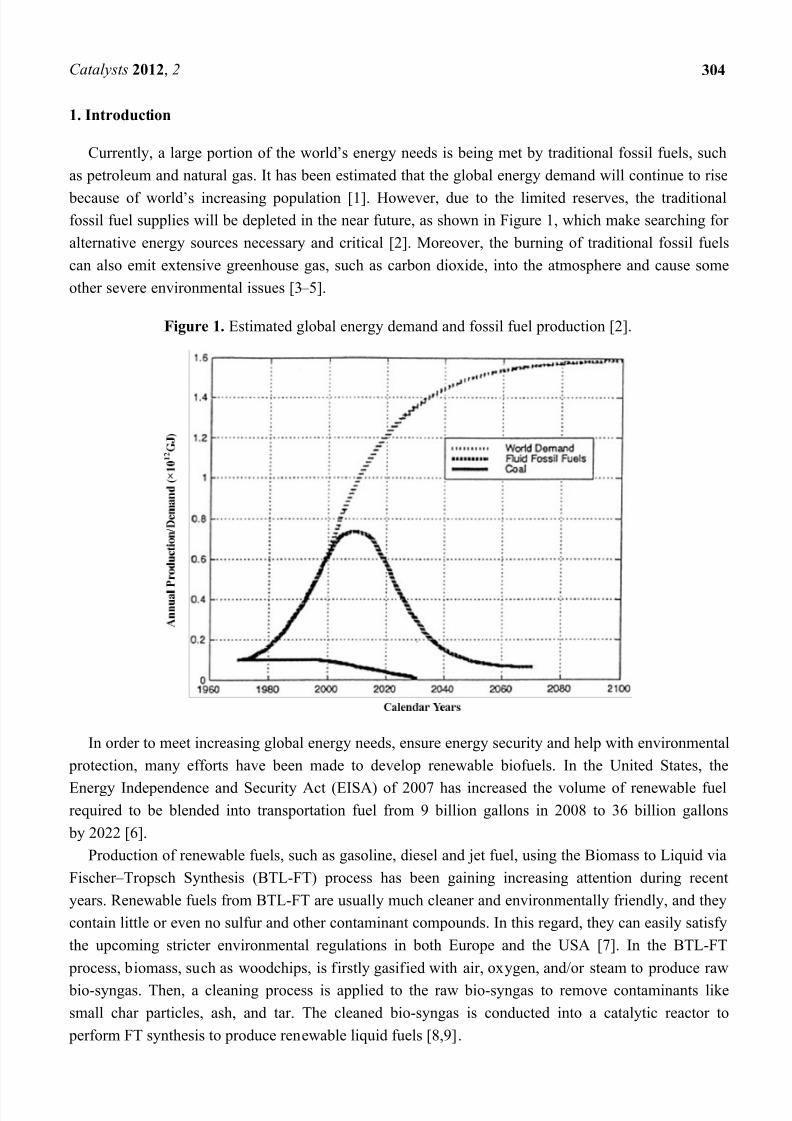
because of world’s increasing population [1]. However, due to the limited reserves, the traditionalfossil fuel supplies will be depleted in the near future, as shown in Figure 1, which make searching for
alternative energy sources necessary and critical [2]. Moreover, the burning of traditional fossil fuels
can also emit extensive greenhouse gas, such as carbon dioxide, into the atmosphere and cause some
other severe environmental issues [3 – 5].
Figure 1. Estimated global energy demand and fossil fuel production [2].
In order to meet increasing global energy needs, ensure energy security and help with environmental
protection, many efforts have been made to develop renewable biofuels. In the United States, the
Energy Independence and Security Act (EISA) of 2007 has increased the volume of renewable fuelrequired to be blended into transportation fuel from 9 billion gallons in 2008 to 36 billion gallons
by 2022 [6].
Production of renewable fuels, such as gasoline, diesel and jet fuel, using the Biomass to Liquid via
Fischer – Tropsch Synthesis (BTL-FT) process has been gaining increasing attention during recent
years. Renewable fuels from BTL-FT are usually much cleaner and environmentally friendly, and they
contain little or even no sulfur and other contaminant compounds. In this regard, they can easily satisfy
the upcoming stricter environmental regulations in both Europe and the USA [7]. In the BTL-FT
process, biomass, such as woodchips, is firstly gasified with air, oxygen, and/or steam to produce raw
bio-syngas. Then, a cleaning process is applied to the raw bio-syngas to remove contaminants like
small char particles, ash, and tar. The cleaned bio-syngas is conducted into a catalytic reactor to
perform FT synthesis to produce renewable liquid fuels [8,9].
7/26/2019 Application of Fischer-Tropsch Synthesis in Biomass to Liquid Conversion
http://slidepdf.com/reader/full/application-of-fischer-tropsch-synthesis-in-biomass-to-liquid-conversion 3/24
Catalysts 2012, 2 305
Bio-syngas resulting from biomass gasification contains CO, H2, CO2, CH4, and N2 in various
proportions [10,11]. The average bio-syngas from a downdraft gasifier with air as the oxidant contains
22.16% CO, 17.55% H2, 11.89% CO2, 3.07% CH4, with N2 and other gases as the balance [12].
Fischer – Tropsch synthesis (FTS) is the process of producing liquid hydrocarbons from synthesis
gas (CO and H2). Its feedstock can be coal, natural gas, biomass or other solid carbon sources.
Traditional FTS catalysts, such as Fe-, Co-, and Ni-based catalysts, have been extensively studied in the
literature [13 – 20].
This review will analyze the three main steps of the BTL-FT process and discuss the issues related
to biomass gasification, bio-syngas cleaning methods and conversion of bio-syngas into liquid
hydrocarbons via Fischer – Tropsch synthesis. Some features regarding increasing carbon utilization,
enhancing catalyst activity, maximizing selectivity and avoiding catalyst deactivation in the bio-syngas
conversion process are also discussed.
2. Process Analysis
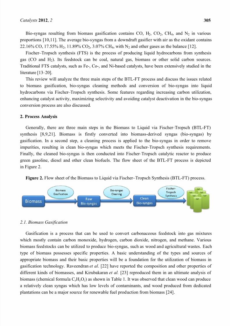
Generally, there are three main steps in the Biomass to Liquid via Fischer – Tropsch (BTL-FT)
synthesis [8,9,21]. Biomass is firstly converted into biomass-derived syngas (bio-syngas) by
gasification. In a second step, a cleaning process is applied to the bio-syngas in order to remove
impurities, resulting in clean bio-syngas which meets the Fischer – Tropsch synthesis requirements.
Finally, the cleaned bio-syngas is then conducted into Fischer – Tropsch catalytic reactor to produce
green gasoline, diesel and other clean biofuels. The flow sheet of the BTL-FT process is depicted
in Figure 2.
Figure 2. Flow sheet of the Biomass to Liquid via Fischer – Tropsch Synthesis (BTL-FT) process.
2.1. Biomass Gasification
Gasification is a process that can be used to convert carbonaceous feedstock into gas mixtures
which mostly contain carbon monoxide, hydrogen, carbon dioxide, nitrogen, and methane. Various
biomass feedstocks can be utilized to produce bio-syngas, such as wood and agricultural wastes. Each
type of biomass possesses specific properties. A basic understanding of the types and sources of
appropriate biomass and their basic properties will be a foundation for the utilization of biomass in
gasification technology. Raveendran et al . [22] have reported the composition and other properties of
different kinds of biomasses, and Kirubakaran et al. [23] reproduced them in an ultimate analysis of
biomass (chemical formula C xH yO z ) as shown in Table 1. It was observed that clean wood can produce
a relatively clean syngas which has low levels of contaminants, and wood produced from dedicated plantations can be a major source for renewable fuel production from biomass [24].
7/26/2019 Application of Fischer-Tropsch Synthesis in Biomass to Liquid Conversion
http://slidepdf.com/reader/full/application-of-fischer-tropsch-synthesis-in-biomass-to-liquid-conversion 4/24
Catalysts 2012, 2 306
Table 1. Ultimate analysis of biomass [23].
Biomass
Ultimate analysis
(wt%)HHV
a
(MJ/kg)
Density
(kg/m3)
x y z
Percentage
conversion
of carbonC H N O
Bagasse 43.8 5.8 0.4 47.1 16.29 111 3.65 5.8 2.94 81
Coconut coir 47.6 5.7 0.2 45.6 14.67 151 3.97 5.7 2.85 72
Coconut Shell 50.2 5.7 0 43.4 20.5 661 4.18 5.7 2.71 65
Coir pith 44 4.7 0.7 43.4 18.07 94 3.67 4.7 2.71 74
Corn Cob 47.6 5 0 44.6 15.65 188 3.97 5 2.79 70
Corn stalks 41.9 5.3 0 46 16.54 129 3.49 5.3 2.88 82.3
Cotton gin waste 42.7 6 0.1 49.5 17.48 109 3.56 6 3.1 87
Ground nut shell 48.3 5.7 0.8 39.4 18.65 299 4.03 5.7 2.46 61.2
Millet husk 42.7 6 0.1 33 17.48 201 3.56 6 2.06 58
Rice husk 38.9 5.1 0.6 32 15.29 617 3.24 5.1 2 62
Rice straw 36.9 5 0.4 37.9 16.78 259 3.08 5 2.37 82.4
Subabul wood 48.2 5.9 0 45.1 19.78 259 4.02 5.9 2.82 70.2
Wheat straw 47.5 5.4 0.1 35.8 17.99 222 3.96 5.4 2.24 56.5
AVERAGE 44.6 5.5 0.3 41.8 17.32 253.84 3.72 5.49 2.61 70.89a Higher Heating Value.
Pre-treatment before gasification is necessary and generally includes screening, size reduction, and
drying [25]. Smaller biomass particle size will provide more surface area and porous structures per unit
biomass, which will facilitate heat transfer and biomass conversion during the gasification process.
However, in most gasifiers, the biomass feed has to withstand the flow of gasifying agent with anappropriate size and weight; feed particle sizes are most often in the range of 20 to 80 mm [26]. Drying
is the most important process in the pre-treatment. Drier biomass can improve the efficiency of
gasification, but also reduces the hydrogen content in the gas product, which is unfavorable in the
following Fischer – Tropsch synthesis. Drying can reduce the moisture content of the biomass feedstock
to 10% – 15% [27].
Some other pretreatment technologies, such as torrefaction, pyrolysis, and pelletization, also need to
be mentioned.
Torrefaction is a thermal pretreatment technology which is performed at atmospheric pressure
without the appearance of oxygen at around 200 to 300 °C. Torrefaction can convert fresh biomass into
a solid uniform product, which has a low moisture content and high calorific value. The torrefaction
process involves initial heating, pre-drying, post-drying and intermediate heating stages [28].
Pyrolysis is a process involving the direct thermal decomposition of biomass in the absence of
oxygen at a moderate temperature of around 400 to 800 °C. The pyrolysis products are generally gas,
liquid, and solid char. Their proportions depend on the pyrolysis method employed and the properties
of the feed biomass [29,30].
Pelletization can be described as drying and compressing biomass to produce cylindrical biomass
pellets. Those pellets have smaller volume and higher volumetric energy density compared to raw
biomass and thus are easy and efficient to store, transport and use in energy conversion [31].
Torrefaction can provide the highest process efficiency (94%) compared to pyrolysis (64%) and
pelletization (84%) [32].
7/26/2019 Application of Fischer-Tropsch Synthesis in Biomass to Liquid Conversion
http://slidepdf.com/reader/full/application-of-fischer-tropsch-synthesis-in-biomass-to-liquid-conversion 5/24
Catalysts 2012, 2 307
Several types of gasifiers are designed with different hydrodynamics, using different gasification
agents (air, oxygen, oxygen-rich air and/or stream) and operation conditions. The most widely used
types are updraft fixed bed gasifiers, downdraft fixed bed gasifiers, fluidized-bed gasifiers, and
entrained flow gasifiers [33].
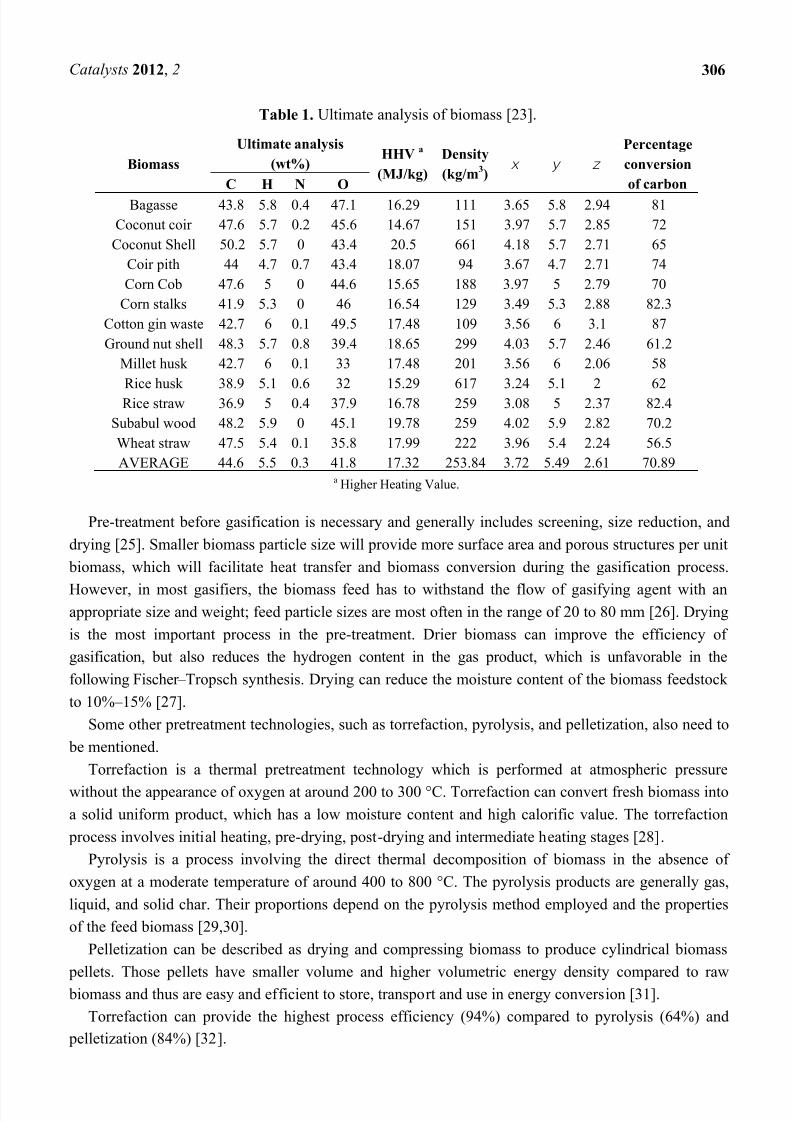
In the updraft fixed bed gasifier, as shown in Figure 3, the biomass feed is introduced into the top
oft he gasifier and falls downwards when the gasifying agent comes into the bottom of the grate and
then goes upwards. The combustion happens at the bottom of the bed, and the gas product is released
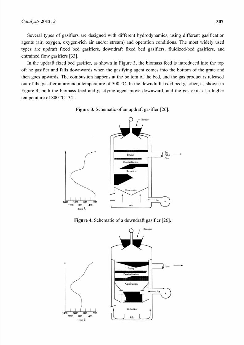
out of the gasifier at around a temperature of 500 °C. In the downdraft fixed bed gasifier, as shown in
Figure 4, both the biomass feed and gasifying agent move downward, and the gas exits at a higher
temperature of 800 °C [34].
Figure 3. Schematic of an updraft gasifier [26].
Figure 4. Schematic of a downdraft gasifier [26].
7/26/2019 Application of Fischer-Tropsch Synthesis in Biomass to Liquid Conversion
http://slidepdf.com/reader/full/application-of-fischer-tropsch-synthesis-in-biomass-to-liquid-conversion 6/24
Catalysts 2012, 2 308
In the fluidized bed gasifier, the biomass feed is introduced into the gasifier bottom and then
fluidized using air, oxygen or another gasifying agent. Such kinds of gasifiers can increase the reaction
rates and conversion efficiencies by enhancing the heat transfer during the gasification. Fluidized beds
can be further divided into bubbling fluidized beds and circulating fluidized beds [34].
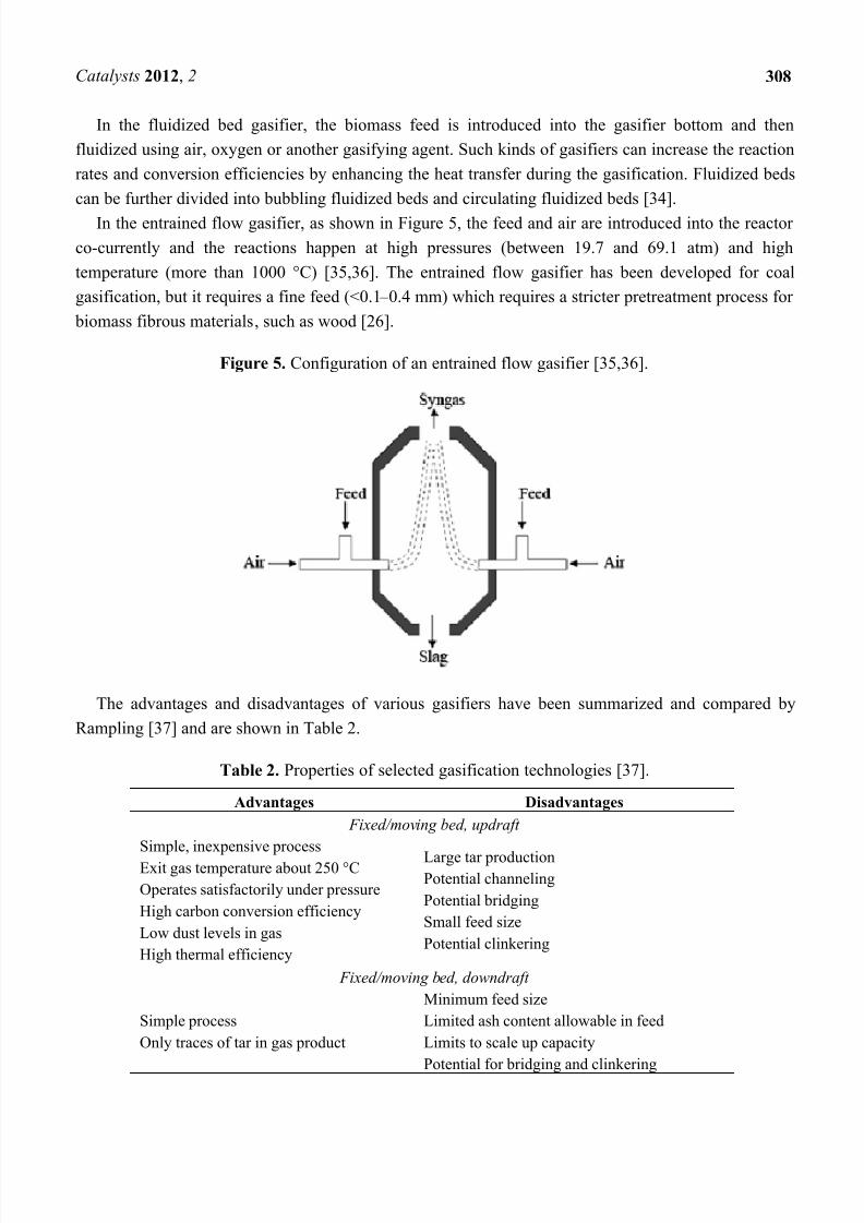
In the entrained flow gasifier, as shown in Figure 5, the feed and air are introduced into the reactor
co-currently and the reactions happen at high pressures (between 19.7 and 69.1 atm) and high
temperature (more than 1000 °C) [35,36]. The entrained flow gasifier has been developed for coal
gasification, but it requires a fine feed (<0.1 – 0.4 mm) which requires a stricter pretreatment process for
biomass fibrous materials, such as wood [26].
Figure 5. Configuration of an entrained flow gasifier [35,36].
The advantages and disadvantages of various gasifiers have been summarized and compared by
Rampling [37] and are shown in Table 2.
Table 2. Properties of selected gasification technologies [37].
Advantages Disadvantages
Fixed/moving bed, updraft
Simple, inexpensive process
Exit gas temperature about 250 °C
Operates satisfactorily under pressure
High carbon conversion efficiency
Low dust levels in gas
High thermal efficiency
Large tar productionPotential channeling
Potential bridging
Small feed size
Potential clinkering
Fixed/moving bed, downdraft
Simple process
Only traces of tar in gas product
Minimum feed size
Limited ash content allowable in feed
Limits to scale up capacity
Potential for bridging and clinkering
7/26/2019 Application of Fischer-Tropsch Synthesis in Biomass to Liquid Conversion
http://slidepdf.com/reader/full/application-of-fischer-tropsch-synthesis-in-biomass-to-liquid-conversion 7/24
Catalysts 2012, 2 309
Table 2. Cont.
Fluidized bed
Flexible feed rate and composition
High ash fuels acceptable
Able to pressurize
High CH4 in gas product
High volumetric capacity
Easy temperature control
Operating temperature limited by ash clinkering
High gas product temperature
High tar and fines content in gas
Possibility of high C content in fly ash
Circulating fluidized bed
Flexible process
Up to 850 °C operating temperature
Corrosion and attrition problems
Poor operational control using biomass
Double fluidized bed
Oxygen not required
High CH4 due to low bed
Temperature
Temperature limit in the oxidizer
More tar due to lower bed temperature
Difficult to operate under pressure
Entrained bed
Very low in tar and CO2
Flexible to feedstock
Exit gas temperature
Low in CH4
Extreme feedstock size reduction required
Complex operational control
Carbon loss with ash
Ash slagging
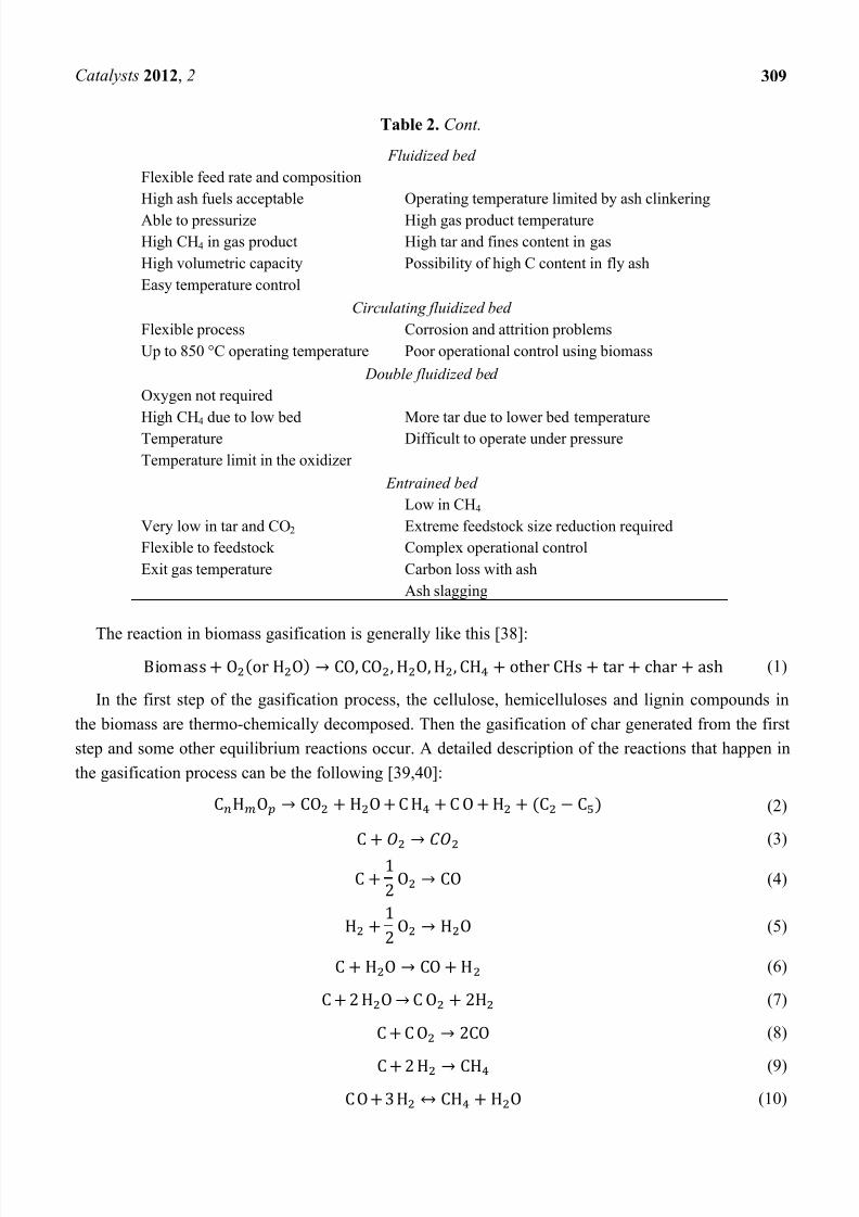
The reaction in biomass gasification is generally like this [38]:
(1)
In the first step of the gasification process, the cellulose, hemicelluloses and lignin compounds in
the biomass are thermo-chemically decomposed. Then the gasification of char generated from the first
step and some other equilibrium reactions occur. A detailed description of the reactions that happen in
the gasification process can be the following [39,40]:
(2)
(3)
(4)
(5)
(6)
(7)
(8)
(9)
(10)

7/26/2019 Application of Fischer-Tropsch Synthesis in Biomass to Liquid Conversion
http://slidepdf.com/reader/full/application-of-fischer-tropsch-synthesis-in-biomass-to-liquid-conversion 8/24
Catalysts 2012, 2 310
(11)
The composition of the product gas from a gasifier will be influenced by several parameters [41,42],
such as feedstock composition, moisture content of the feedstock, gasifying agents, operation pressure,
operation temperature, etc. It is difficult to predict the composition of the gas product from a gasifier
due to the complex reactions occurred during the gasification. Table 3 shows the typical composition
of gas produced from gasification of wood and charcoal with low to medium moisture content with
ambient air as the gasifying agent in a downdraft gasifier [43] and composition of bio-syngas from
biomass gasification [44 – 46].
Table 3. Composition of gas produced from gasification of wood and charcoal in ambient
air [43] and also the composition of typical nitrogen free bio-syngas [44 – 46].
Component Wood gas (air) Charcoal gas (air) Bio-syngas (nitrogen free)
N2 50 – 60 55 – 65 0
CO 14 – 25 28 – 32 28 – 36
CO2 9 – 15 1 – 3 22 – 32
H2 10 – 20 4 – 10 21 – 30
CH4 2 – 6 0 – 2 8 – 11
C2H4 n/a n/a 2 – 4
BTX n/a n/a 0.84 – 0.96
C2H5 n/a n/a 0.16 – 0.22
Tar n/a n/a 0.15 – 0.24
Others n/a n/a <0.021
Some other critical issues in biomass gasification, such as the effects of gasification temperature,
biomass flow rate, type and properties and gasifying agent types on the product properties, can be
found in previous research work [47 – 51].
2.2. Bio-Syngas Cleaning
The biomass feedstock is pretreated and the gasification technologies are optimized to efficiently
produce bio-syngas with the desired content of carbon monoxide and hydrogen. However, some
amounts of impurities will show in the raw bio-syngas. Those impurities can lower the FT activity in
the bio-syngas catalytic conversion, so it is necessary to remove them to meet the Fischer – Tropsch
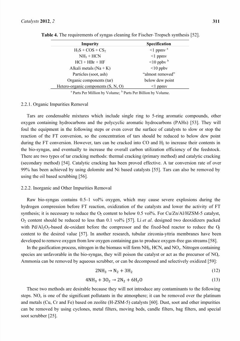
synthesis specifications [52], which are shown in Table 4.
Generally, the impurities in bio-syngas produced from the gasifier can be grouped into three types:
(1) organic impurities, such as tars, Benzene, Toluene, and Xylenes (BTX); (2) inorganic impurities,
such as O2, NH3, HCN, H2S, COS, and HCl; (3) other impurities, such as dust and soot.
7/26/2019 Application of Fischer-Tropsch Synthesis in Biomass to Liquid Conversion
http://slidepdf.com/reader/full/application-of-fischer-tropsch-synthesis-in-biomass-to-liquid-conversion 9/24
Catalysts 2012, 2 311
Table 4. The requirements of syngas cleaning for Fischer – Tropsch synthesis [52].
Impurity Specification
H2S + COS + CS2 <1 ppmva
NH3 + HCN <1 ppmv
HCl + HBr + HF <10 ppbv b
Alkali metals (Na + K) <10 ppbv
Particles (soot, ash) “almost removed”
Organic components (tar) below dew point
Hetero-organic components (S, N, O) <1 ppmva Parts Per Million by Volume;
b Parts Per Billion by Volume.
2.2.1. Organic Impurities Removal
Tars are condensable mixtures which include single ring to 5-ring aromatic compounds, other
oxygen containing hydrocarbons and the polycyclic aromatic hydrocarbons (PAHs) [53]. They will
foul the equipment in the following steps or even cover the surface of catalysts to slow or stop the
reaction of the FT conversion, so the concentration of tars should be reduced to below dew point
during the FT conversion. However, tars can be cracked into CO and H2 to increase their contents in
the bio-syngas, and eventually to increase the overall carbon utilization efficiency of the feedstock.
There are two types of tar cracking methods: thermal cracking (primary method) and catalytic cracking
(secondary method) [54]. Catalytic cracking has been proved effective. A tar conversion rate of over
99% has been achieved by using dolomite and Ni based catalysts [55]. Tars can also be removed by
using the oil based scrubbing [56].
2.2.2. Inorganic and Other Impurities Removal
Raw bio-syngas contains 0.5 – 1 vol% oxygen, which may cause severe explosions during the
hydrogen compression before FT reaction, oxidization of the catalysts and lower the activity of FT
synthesis; it is necessary to reduce the O2 content to below 0.5 vol%. For Cu/Zn/Al/HZSM-5 catalyst,
O2 content should be reduced to less than 0.1 vol% [57]. Li et al . designed two deoxidizers packed
with Pd/Al2O3-based de-oxidant before the compressor and the fixed-bed reactor to reduce the O2
content to the desired value [57]. In another research, tubular zirconia-yttria membranes have been
developed to remove oxygen from low oxygen containing gas to produce oxygen-free gas streams [58].
In the gasification process, nitrogen in the biomass will form NH3, HCN, and NO x. Nitrogen containing
species are unfavorable in the bio-syngas, they will poison the catalyst or act as the precursor of NO x.
Ammonia can be removed by aqueous scrubber, or can be decomposed and selectively oxidized [59]:
(12)
(13)
These two methods are desirable because they will not introduce any contaminants to the following
steps. NO x is one of the significant pollutants in the atmosphere; it can be removed over the platinum
and metals (Cu, Cr and Fe) based on zeolite (H-ZSM-5) catalysts [60]. Dust, soot and other impurities
can be removed by using cyclones, metal filters, moving beds, candle filters, bag filters, and special
soot scrubber [25].
7/26/2019 Application of Fischer-Tropsch Synthesis in Biomass to Liquid Conversion
http://slidepdf.com/reader/full/application-of-fischer-tropsch-synthesis-in-biomass-to-liquid-conversion 10/24
Catalysts 2012, 2 312
Sulfur contaminants from the biomass gasification can take up the active sites of catalysts and
reduce the catalytic activity during the reaction. A current approach in the coal industry is the use of a
sulfur sorbent, like ZnO, to absorb H2S and form ZnS to protect catalysts from sulfur poisoning [61].
2.3. Fischer – Tropsch Synthesis
The Fischer – Tropsch process or Fischer – Tropsch synthesis is a set of catalytic processes for
converting synthesis gas (syngas, carbon monoxide hydrogen and/or other gases mixture) into liquid
hydrocarbons. It was first introduced by Han Fischer and Franz Tropsch in 1923 [62]. The
Fischer – Tropsch process has now become a key component in Gas to Liquid (GTL) technology.
The reactions in the Fischer – Tropsch process are generally described as the following:
(14)
(15)
(16)
(17)
Except alkanes (Equation 14) and alkenes (Equation 15), some oxygenates (Equation 16) may be
also formed during the Fischer – Tropsch process. A water gas shift (WGS) reaction (Equation 17)
occurring during the process can be used to adjust the ratio of carbon monoxide and hydrogen.
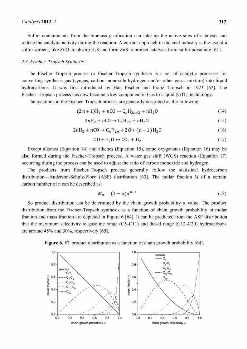
The products from Fischer – Tropsch process generally follow the statistical hydrocarbon
distribution — Anderson-Schulz-Flory (ASF) distribution [63]. The molar fraction M of a certain
carbon number of n can be described as:
(18)
So product distribution can be determined by the chain growth probability α value. The product
distribution from the Fischer – Tropsch synthesis as a function of chain growth probability in molar
fraction and mass fraction are depicted in Figure 6 [64]. It can be predicted from the ASF distribution
that the maximum selectivity to gasoline range (C5 – C11) and diesel range (C12 – C20) hydrocarbons
are around 45% and 30%, respectively [65].
Figure 6. FT product distribution as a function of chain growth probability [64].
7/26/2019 Application of Fischer-Tropsch Synthesis in Biomass to Liquid Conversion
http://slidepdf.com/reader/full/application-of-fischer-tropsch-synthesis-in-biomass-to-liquid-conversion 11/24
Catalysts 2012, 2 313
Commercially available FT reactors nowadays have two different temperature ranges. The high
temperature FT (HTFT) reactor runs with iron catalysts at around 340 °C, and is used to produce
olefins and gasoline. The low temperature FT (LTFT) reactor uses iron or cobalt based catalysts at
around 230 °C, and is used to produce diesel and linear waxes [66]. Generally, commercially
established FT reactors can be divided into three main categories: fixed bed, fluid bed and slurry FT
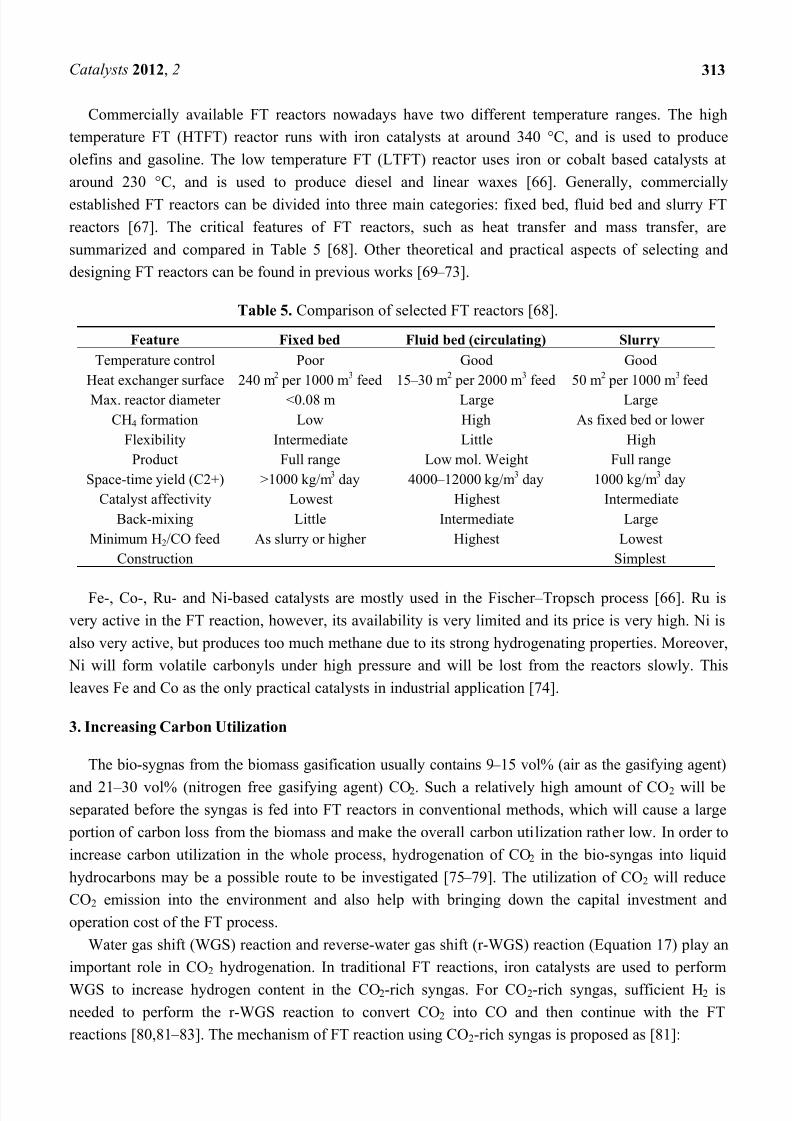
reactors [67]. The critical features of FT reactors, such as heat transfer and mass transfer, are
summarized and compared in Table 5 [68]. Other theoretical and practical aspects of selecting and
designing FT reactors can be found in previous works [69 – 73].
Table 5. Comparison of selected FT reactors [68].
Feature Fixed bed Fluid bed (circulating) Slurry
Temperature control Poor Good Good
Heat exchanger surface 240 m2 per 1000 m
3 feed 15 – 30 m
2 per 2000 m
3 feed 50 m
2 per 1000 m
3feed
Max. reactor diameter <0.08 m Large Large
CH4 formation Low High As fixed bed or lower
Flexibility Intermediate Little High
Product Full range Low mol. Weight Full range
Space-time yield (C2+) >1000 kg/m3 day 4000 – 12000 kg/m
3 day 1000 kg/m
3 day
Catalyst affectivity Lowest Highest Intermediate
Back-mixing Little Intermediate Large
Minimum H2/CO feed As slurry or higher Highest Lowest
Construction Simplest
Fe-, Co-, Ru- and Ni-based catalysts are mostly used in the Fischer – Tropsch process [66]. Ru is
very active in the FT reaction, however, its availability is very limited and its price is very high. Ni is
also very active, but produces too much methane due to its strong hydrogenating properties. Moreover,
Ni will form volatile carbonyls under high pressure and will be lost from the reactors slowly. This
leaves Fe and Co as the only practical catalysts in industrial application [74].
3. Increasing Carbon Utilization
The bio-sygnas from the biomass gasification usually contains 9 – 15 vol% (air as the gasifying agent)
and 21 – 30 vol% (nitrogen free gasifying agent) CO2. Such a relatively high amount of CO2 will beseparated before the syngas is fed into FT reactors in conventional methods, which will cause a large
portion of carbon loss from the biomass and make the overall carbon utilization rather low. In order to
increase carbon utilization in the whole process, hydrogenation of CO2 in the bio-syngas into liquid
hydrocarbons may be a possible route to be investigated [75 – 79]. The utilization of CO2 will reduce
CO2 emission into the environment and also help with bringing down the capital investment and
operation cost of the FT process.
Water gas shift (WGS) reaction and reverse-water gas shift (r-WGS) reaction (Equation 17) play an
important role in CO2 hydrogenation. In traditional FT reactions, iron catalysts are used to perform
WGS to increase hydrogen content in the CO2-rich syngas. For CO2-rich syngas, sufficient H2 is
needed to perform the r-WGS reaction to convert CO2 into CO and then continue with the FT
reactions [80,81 – 83]. The mechanism of FT reaction using CO2-rich syngas is proposed as [81]:
7/26/2019 Application of Fischer-Tropsch Synthesis in Biomass to Liquid Conversion
http://slidepdf.com/reader/full/application-of-fischer-tropsch-synthesis-in-biomass-to-liquid-conversion 12/24
Catalysts 2012, 2 314
(19)
The reaction stoichiometry of CO2 hydrogenation suggests the ratio of hydrogen to CO and CO 2 to
be between 2 and 3 in the bio-syngas. However, the ratio of hydrogen to CO and CO2 in bio-syngas
from the biomass gasification is lower than 2, thus more investigations into increasing the hydrogencontent in bio-syngas or finding additional cheap hydrogen source are needed in the future.
Thomas Riedel [84] made a comparative study of CO2 by using iron and cobalt based catalysts in
the environments of both H2/CO and H2/CO2. They found that iron and cobalt catalysts behaved
differently in CO2 hydrogenation. By using cobalt catalysts, CO2 acts only as a diluent. With more CO2
in the feed gas, more methane was formed. However with iron catalysts, the composition of the
hydrocarbon products of H2/CO2 feed gas is the same as obtained from H2/CO feed gas, with no
excessive methane formed. So it is possible to use an iron catalyst to perform Fischer – Tropsch CO2
hydrogenation rather than cobalt catalyst. Zhang [85] found similar results regarding cobalt catalyst in
CO2 hydrogenation. With cobalt catalysts, the products of CO2 hydrogenation are 70% or moremethane. Dorner et al. [86] added Pt to Cobalt catalyst to investigate conversion of CO2 into valuable
hydrocarbons. Different feed gas ratios of H2 and CO2 (3:1, 2:1, and 1:1) were used in the research.
With the shift of gas ratios of H2 and CO2 from 3:1 to 1:1, it was found that the product distribution
moved from methane to higher hydrocarbons.
4. Enhancing Catalyst Activity
Promoters are used to enhance activity and modify the selectivity to target products [87 – 93]. In
Fischer – Tropsch synthesis, there is no need to use any promoter for Ru-based catalysts due to its high
catalytic activity. However, Fe- and Co-based catalysts generally require alkali metals, transition
metals and noble metals to promote their activities to achieve desired performance [94].
For Fe-based catalysts, alkali metals are used to change the electronic properties of Fe-based
catalysts, and to enhance the CO chemisorption during the reaction, and then to promote the activity of
the Fe-based catalysts. The effect of potassium promoter on the performance of the iron-manganese
catalyst was investigated by Yang et al . [95]. The relatively large crystallite sizes of α-Fe2O3,
inhibition of the reduction of catalyst and enhancement carbonization of the catalyst were observed
due to the addition of potassium in the experiment. A maximum FTS activity was achieved in 0.7% K
content. With increasing potassium level, selectivity to olefins was promoted and the formation ofmethane and light hydrocarbons was restrained. The addition of potassium was found to enhance the
activity of the catalyst and also the water gas shift reaction. However, a high content of potassium may
lead to deactivation of the catalyst [96,97].
The addition of copper into Fe-based catalyst was found to help with the reduction of catalyst
precursor and then to increase its activity. Catalytic behavior of Cu-promoted Fe – Mn – K/SiO2 catalysts
was studied by Zhang et al . [98]; copper improved the catalyst activation rate and shortened the
induction period, but the addition of Cu showed no apparent influence on the steady-state activity of
the catalyst.
The effects of various transition metals (Cr, Mn, Mo, Ta, V, W, and Zr) on the catalytic
performance of Fe-based catalysts were investigated by Lohitharn et al . [99]. They found that those
transition metals (except W) increased CO hydrogenation activity in Fe-based catalysts. Cr-, Mn- and
7/26/2019 Application of Fischer-Tropsch Synthesis in Biomass to Liquid Conversion
http://slidepdf.com/reader/full/application-of-fischer-tropsch-synthesis-in-biomass-to-liquid-conversion 13/24
Catalysts 2012, 2 315
Zr-promoted catalysts showed higher catalytic activities than the other transition metals did. However,
the presence of transition metal did not affect the hydrocarbons distribution in the products.
Some transitional metals, noble metals and rare earth metals are used as promoters in the Co-based
catalyst. The addition of Pt, Ru and Pd to the Co-based catalysts enhanced the reduction of the cobalt
oxides, and increased the overall activity of the promoted catalysts [100]. Rhenium is also widely used
to promote the cobalt catalyst [101,102]. ZrO2 proved to be a very good promoter for cobalt catalyst, it
can improve the CO conversion rate and C5+ selectivity [103 – 105].
5. Selectivity Maximization
Conventional FT synthesis usually generates products which follow the ASF distribution and is
typically unselective to generate from light to heavy hydrocarbons. Thus, controlling and maximizing
selectivity is one of biggest challenges in FT synthesis research. A lot of research progress has been
made in the past [106 – 113]. Here we will primarily discuss selectivity control and maximizationthrough bi-functional FT catalysts.
The bi-functional catalysts were first successfully proposed by Chang et al . [114] in 1978.
Traditional Fischer – Tropsch synthesis needs post-cracking or refinery to achieve the desired products.
However, by using bi-functional catalysts, the transformation of syngas into liquid hydrocarbons
directly with the certain desired carbon number range was made possible. Bi-functional catalysts
contain metallic (syngas to alcohol) and acidic (alcohol to hydrocarbon) components, they can be used
in a single reactor to synthesize methanol with metallic component and transform methanol into
hydrocarbons with zeolite simultaneously [115].
The bi-functional catalyst Cr 2O3-ZnO/ZSM-5 was extensively investigated [114,116 – 118] in the
past decades due to its satisfactory performance in high octane gasoline synthesis. Liu et al . [119,120]
recently developed a Mo/HZSM-5 bi-functional catalyst and found it active in Fischer – Tropsch
synthesis to produce high octane gasoline range hydrocarbons. The catalysts were evaluated under
various reaction conditions with H2/CO = 1 syngas which is the typical composition of the bio-syngas
from biomass gasification. Liquid hydrocarbons from Mo/HZSM-5 catalyst were composed mainly of
alkyl-substituted aromatics and lower branched and cyclized alkanes. Small amount of alcohols were
detected in the water phase. They proposed the mechanism of formation of hydrocarbons on
Mo/zeolite is through molybdenum metal catalysis via mixed alcohols as the intermediates.
Other than alcohol intermediate route bi-functional catalysts, many studies have added zeolites to
the conventional Fischer – Tropsch system. In the traditional Fischer – Tropsch process, the product
distribution follows ASF function, so the syngas to gasoline range hydrocarbon (C5 – C12) selectivity
can only achieve around 48% [121]. Besides, traditional Fischer – Tropsch synthesis products contain
primarily linear paraffins and olefins [122], which lead to a low octane number of the gasoline.
Zeolites have a shape-selective property, which can restrain the formation of products that are larger
than the size of the channels of zeolite and result in lighter hydrocarbons. Moreover, the acid site of
zeolites can help with cracking, isomerization and aromatization reactions for the Fischer – Tropsch
products. The cracking of longer chain hydrocarbons and light olefins oligomerization will increase theyield of certain carbon range hydrocarbons, such as gasoline range hydrocarbons (C5 – C12), the
branched and oligomerized hydrocarbons from zeolite catalysts containing catalysts possessing high
7/26/2019 Application of Fischer-Tropsch Synthesis in Biomass to Liquid Conversion
http://slidepdf.com/reader/full/application-of-fischer-tropsch-synthesis-in-biomass-to-liquid-conversion 14/24
Catalysts 2012, 2 316
octane number. This property can help with overcoming the limitation of ASF distribution and
adjustment of the Fischer – Tropsch product distributions.
Various combinations of Fischer – Tropsch catalysts and zeolites have been investigated.
Guczi et al . [123] found that Ru/NaY was very active in Fischer – Tropsch conversion with 86% of CO
conversion rate, while Co/NaY showed a very low CO conversion rate in the test. Wang et al . [124]
concluded that Fe/NaX and Fe/NaY provided higher conversion rates and higher C5+ selectivity than
other combinations of Fe and zeolites. The other zeolites mixed with FT catalyst system which
have been investigated were faujasites, MCM-22 [125], ITQ-2, ITQ-6, ZSM-5, ZSM-11, ZSM-12,
ZSM-34 [126], etc.
6. Catalyst Deactivation
The activity and catalyst life time have been primary concerns in the large-scale catalytic process,
since they can greatly affect the productivity and the economic aspect of the whole process. Thus, it isessential to study how to avoid catalyst deactivation during the bio-syngas liquefaction process.
Catalyst decay can be found in many pathways: mechanically, thermally and chemically. Here we will
primarily discuss three categories of catalyst deactivation.
6.1. Carbon Deposition Related Deactivation
Fouling is the mechanical deposition of impurities from the feed gas, which will block the active
sites or catalyst channels and then decrease the catalytic activities. The organic impurities, such as tar,
when condensed could be a source of catalyst fouling. Therefore, it is beneficial to remove the tar fromraw bio-syngas cleaning in the upstream process [127].
The origin of coke and carbon deposition is different from fouling, which is the product of CO
disproportionation and decomposition or condensation of hydrocarbons on the catalyst surfaces during
the catalytic reactions. Typically, coke and carbon deposition will form polymerized long chain
hydrocarbons or primarily carbons, like graphite, according to specific reaction conditions [128,129].
By studying coke and carbon formation mechanisms during the reaction, researchers have made
much progress in developing carbon deactivation resistant catalysts. Rostrup-Nielsen et al . investigated
carbon nucleation rate and tried to slow the coking during the reaction [130]. They used theoretical
density functional theory (DFT) to show that nickel particle size affected the carbon nucleation rate.Bengaard [131] and Besenbacher [132] also controlled the coking rate by promoting the nickel catalyst
with potassium and gold. Other metal catalysts, such as Ru and Rh, have also been investigated in
controlling catalyst deactivation caused by coking [133].
6.2. Sintering (Aging)
Sintering, or aging, is the loss of catalytic activity, which is the result of reducing the catalytic
surface area caused by crystallite growth and loss of support area caused by support collapse or pore
collapse. Sintering mostly occurs at high reaction temperature and its rate will be increased with the
presence of water vapor during the reaction. Various factors can affect the sintering rate of catalysts,
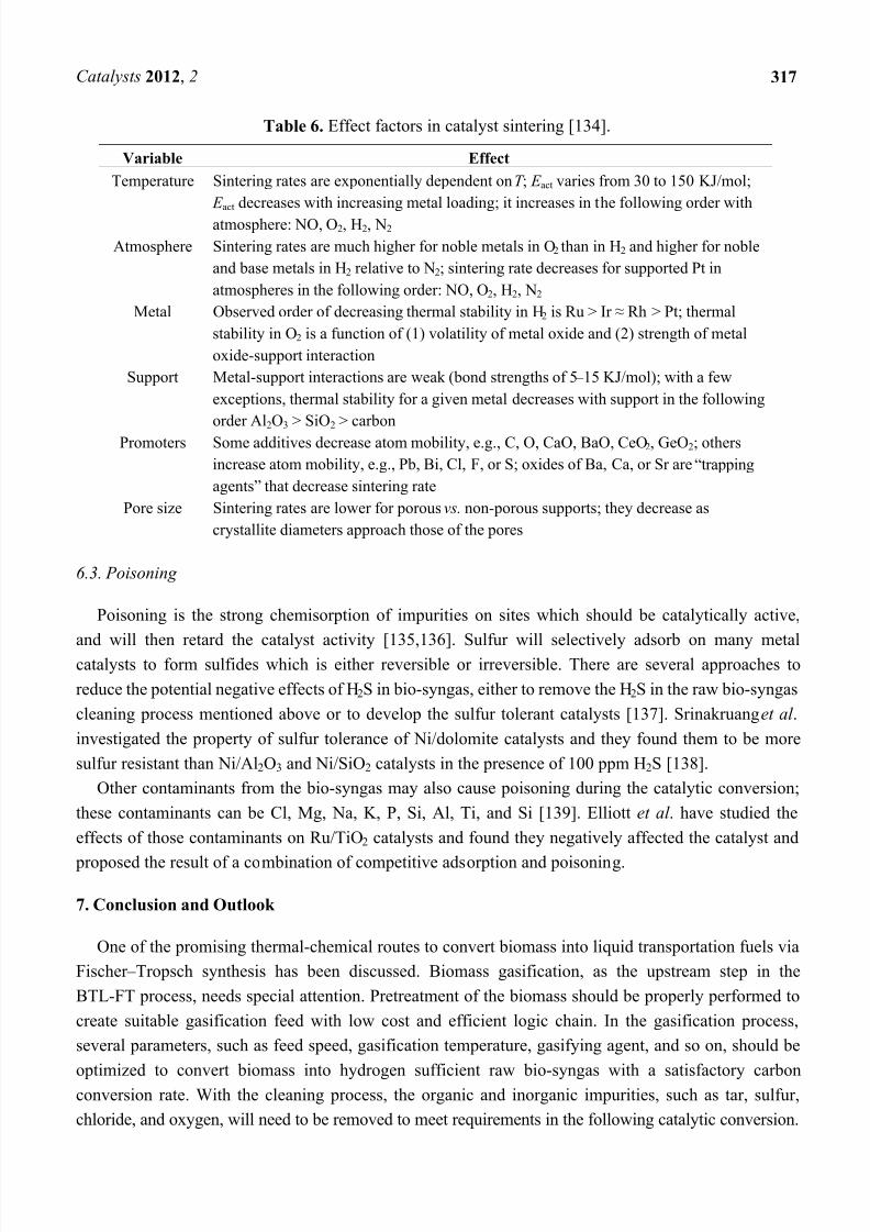
which has been summarized by Bartholomew [134] and is shown in Table 6.
7/26/2019 Application of Fischer-Tropsch Synthesis in Biomass to Liquid Conversion
http://slidepdf.com/reader/full/application-of-fischer-tropsch-synthesis-in-biomass-to-liquid-conversion 15/24
Catalysts 2012, 2 317
Table 6. Effect factors in catalyst sintering [134].
Variable Effect
Temperature Sintering rates are exponentially dependent on T ; E act varies from 30 to 150 KJ/mol;
E act decreases with increasing metal loading; it increases in the following order with
atmosphere: NO, O2, H2, N2
Atmosphere Sintering rates are much higher for noble metals in O2 than in H2 and higher for noble
and base metals in H2 relative to N2; sintering rate decreases for supported Pt in
atmospheres in the following order: NO, O2, H2, N2
Metal Observed order of decreasing thermal stability in H2 is Ru > Ir ≈ Rh > Pt; thermal
stability in O2 is a function of (1) volatility of metal oxide and (2) strength of metal
oxide-support interaction
Support Metal-support interactions are weak (bond strengths of 5 – 15 KJ/mol); with a few
exceptions, thermal stability for a given metal decreases with support in the following
order Al2O3 > SiO2 > carbon
Promoters Some additives decrease atom mobility, e.g., C, O, CaO, BaO, CeO2, GeO2; others
increase atom mobility, e.g., Pb, Bi, Cl, F, or S; oxides of Ba, Ca, or Sr are “trapping
agents” that decrease sintering rate
Pore size Sintering rates are lower for porous vs. non-porous supports; they decrease as
crystallite diameters approach those of the pores
6.3. Poisoning
Poisoning is the strong chemisorption of impurities on sites which should be catalytically active,
and will then retard the catalyst activity [135,136]. Sulfur will selectively adsorb on many metalcatalysts to form sulfides which is either reversible or irreversible. There are several approaches to
reduce the potential negative effects of H2S in bio-syngas, either to remove the H2S in the raw bio-syngas
cleaning process mentioned above or to develop the sulfur tolerant catalysts [137]. Srinakruang et al .
investigated the property of sulfur tolerance of Ni/dolomite catalysts and they found them to be more
sulfur resistant than Ni/Al2O3 and Ni/SiO2 catalysts in the presence of 100 ppm H2S [138].
Other contaminants from the bio-syngas may also cause poisoning during the catalytic conversion;
these contaminants can be Cl, Mg, Na, K, P, Si, Al, Ti, and Si [139]. Elliott et al . have studied the
effects of those contaminants on Ru/TiO2 catalysts and found they negatively affected the catalyst and
proposed the result of a combination of competitive adsorption and poisoning.
7. Conclusion and Outlook
One of the promising thermal-chemical routes to convert biomass into liquid transportation fuels via
Fischer – Tropsch synthesis has been discussed. Biomass gasification, as the upstream step in the
BTL-FT process, needs special attention. Pretreatment of the biomass should be properly performed to
create suitable gasification feed with low cost and efficient logic chain. In the gasification process,
several parameters, such as feed speed, gasification temperature, gasifying agent, and so on, should be
optimized to convert biomass into hydrogen sufficient raw bio-syngas with a satisfactory carbon
conversion rate. With the cleaning process, the organic and inorganic impurities, such as tar, sulfur,
chloride, and oxygen, will need to be removed to meet requirements in the following catalytic conversion.
7/26/2019 Application of Fischer-Tropsch Synthesis in Biomass to Liquid Conversion
http://slidepdf.com/reader/full/application-of-fischer-tropsch-synthesis-in-biomass-to-liquid-conversion 16/24
Catalysts 2012, 2 318
Heat and mass transfer are the critical issues in FT reactor design and selection. The catalyst is the
heart of Fischer – Tropsch synthesis. Higher activity with desired product selection and longer life time
with less catalyst decay should be the priority of the FT catalyst design in future research. More
attention should be paid to increase the carbon utilization in the bio-syngas conversion, to reduce the
greenhouse emissions and to promote the overall rate of carbon conversion into liquid fuels.
Acknowledgments
This material is based upon work performed through the Sustainable Energy Research Center at
Mississippi State University and is supported by the Department of Energy under Awards
(DE-FG3606GO86025, DE-FC2608NT01923) and US Department of Agriculture under Award
(AB567370MSU).
Disclaimer
This report was prepared as an account of work sponsored by an agency of the United States
Government. Neither the United States Government nor any agency thereof, nor any of their
employees, makes any warranty, express or implied, or assumes any legal liability or responsibility for
the accuracy, completeness, or usefulness of any information, apparatus, product, or process disclosed,
or represents that its use would not infringe privately owned rights. Reference herein to any specific
commercial product, process, or service by trade name, trademark, manufacturer, or otherwise does not
necessarily constitute or imply its endorsement, recommendation, or favoring by the United States
Government or any agency thereof. The views and opinions of authors expressed herein do notnecessarily state or reflect those of the United States Government or any agency thereof.
References
1. Kaygusuz, K. Energy for sustainable development: A case of developing countries. Renew.
Sustain. Energy Rev. 2012, 16 , 1116 – 1126.
2. Veziroğlu, T. N.; Şahi'n, S. 21st Century’s energy: Hydrogen energy system. Energy Convers.
Manag. 2008, 49, 1820 – 1831.
3. Davis, S.J.; Caldeira, K. Consumption-based accounting of CO2 emissions. Proc. Natl. Acad. Sci.
USA 2010, 107 , 5687 – 5692.
4. Street, J.; Yu, F. Production of high-value products including gasoline hydrocarbons from
thermochemical conversion of syngas. Biofuels 2011, 2, 677 – 691.
5. Le Quere, C.; Raupach, M.R.; Canadell, J.G.; Marland, G. Trends in the sources and sinks of
carbon dioxide. Nat. Geosci. 2009, 2, 831 – 836.
6. Tilman, D.; Socolow, R.; Foley, J.A.; Hill, J.; Larson, E.; Lynd, L.; Pacala, S.; Reilly, J.;
Searchinger, T.; Somerville, C.; Williams, R. Beneficial biofuels — the food, energy, and
environment trilemma. Science 2009, 325, 270 – 271.
7. Yang, J.H.; Kim, H.J.; Chun, D.H.; Lee, H.T.; Hong, J.C.; Jung, H.; Yang, J.I. Mass transfer
limitations on fixed-bed reactor for Fischer – Tropsch synthesis. Fuel Process. Technol. 2010, 91,
285 – 289.
7/26/2019 Application of Fischer-Tropsch Synthesis in Biomass to Liquid Conversion
http://slidepdf.com/reader/full/application-of-fischer-tropsch-synthesis-in-biomass-to-liquid-conversion 17/24
Catalysts 2012, 2 319
8. Demirbas, A. Global biodiesel strategies. Energy Educ. Sci. Technol. 2006, 17 , 27 – 63.
9. Tijmensen, M.J.A.; Faaij, A.P.C.; Hamelinck, C.N.; van Hardeveld, M.R.M. Exploration of the
possibilities for production of Fischer Tropsch liquids and power via biomass gasification.
Biomass Bioenergy 2002, 23, 129 – 152.
10. Klass, D.L. Biomass for Renewable Energy, Fuels and Chemicals; Academic Press: San Diego,
CA, USA, 1998.
11. Beenackers, A.A.C.M.; Swaaij, W.P.M. Thermochemical Processing of Biomass; Butterworth:
London, UK, 1984.
12. Wei, L.; Thomasson, J.A.; Bricka, R.M.; Sui, R.; Wooten, J.R.; Columbus, E.P. Syngas quality
evaluation for biomass gasification with a downdraft gasifier. Trans. ASABE 2009, 52, 21 – 37.
13. Dry, M.E. The Fischer – Tropsch process: 1950 – 2000. Catal. Today 2002, 71, 227 – 241.
14. den Breejen, J.P.; Radstake, P.B.; Bezemer, G.L.; Bitter, J.H.; Frøseth, V.; Holmen, A.;
de Jong, K.P. On the origin of the cobalt particle size effects in Fischer – Tropsch catalysis. J. Am.
Chem. Soc. 2009, 131, 7197 – 7203.
15. Davis, B.H. Fischer – Tropsch synthesis: Reaction mechanisms for iron catalysts. Catal. Today
2009, 141, 25 – 33.
16. den Breejen, J.P.; Sietsma, J.R.A.; Friedrich, H.; Bitter, J.H.; de Jong, K.P. Design of supported
cobalt catalysts with maximum activity for the Fischer – Tropsch synthesis. J. Catal. 2010, 270,
146 – 152.
17. Khodakov, A.Y. Fischer – Tropsch synthesis: Relations between structure of cobalt catalysts and
their catalytic performance. Catal. Today 2009, 144, 251 – 257.
18. Yan, Z.; Bukur, D.B.; Goodman, D.W. Silica-supported rhodium-cobalt catalysts forFischer – Tropsch synthesis. Catal. Today 2011, 160, 39 – 43.
19. Lualdi, M.; Lögdberg, S.; Regali, F.; Boutonnet, M.; Järås, S. Investigation of mixtures of a
Co-based catalyst and a Cu-based catalyst for the Fischer – Tropsch synthesis with bio-syngas:
The importance of indigenous water. Top. Catal. 2011, 54, 977 – 985.
20. Mogorosi, R.P.; Fischer, N.; Claeys, M.; van Steen, E. Strong-metal-support interaction by
molecular design: Fe-silicate interactions in Fischer – Tropsch catalysts. J. Catal. 2012, 289,
140 – 150.
21. Hamelinck, C.N.; Faaij, A.P.C.; den Uil, H.; Boerrigter, H. Production of FT transportation fuels
from biomass: Technical options, process analysis and optimisation, and development potential.
Energy 2004, 29, 1743 – 1771.
22. Raveendran, K.; Ganesh, A.; Khilar, K.C. Influence of mineral matter on biomass pyrolysis
characteristics. Fuel 1995, 74, 1812 – 1822.
23. Kirubakaran, V.; Sivaramakrishnan, V.; Nalini, R.; Sekar, T.; Premalatha, M.; Subramanian, P.
A review on gasification of biomass. Renew. Sustain. Energy Rev. 2009, 13, 179 – 186.
24. Faaij, A.; van den Broek, R.; van Engelenburg, B.; Lysen, E. Global availability of biomass for
energy and possibilities and constraints for large scale international trade. In Proceedings of the
Fifth International Conference on Greenhouse Gas Control Technologies; Williams, D.J., Ed.;
CSIRO Publishing: Collingwood, Australia, 2001; pp. 1145 – 1151.
7/26/2019 Application of Fischer-Tropsch Synthesis in Biomass to Liquid Conversion
http://slidepdf.com/reader/full/application-of-fischer-tropsch-synthesis-in-biomass-to-liquid-conversion 18/24
Catalysts 2012, 2 320
25. Faaij, A.; van Ree, R.; Meuleman, B. Long Term Perspectives of Biomass Integrated
Gasification with Combined Cycle Technology: Costs and Efficiency and a Comparison with
Combustion; EWAB Report 9840; The Netherlands Agency for Energy and the Environmen
(NOVEM): Utrecht, The Netherlands, 1998.
26. McKendry, P. Energy production from biomass (part 3): Gasification technologies. Bioresour.
Technol. 2002, 83, 55 – 63.
27. van Ree, R.; Oudhuis, A.; Faaij, A.; Curvers, A. Modelling of a Biomass Integrated
Gasifier/Combined Cycle (BIG/CC) System with the Flowsheet Simulation Programme ASPEN+;
ECN Report ECN-C – 95-041; Energy research Centre of the Netherlands (ECN): Petten, The
Netherlands, 1995.
28. Bergman, P.C.A.; Boersma, A.R.; Zwart, R.W.R.; Kiel, J.H.A. Torrefaction for Biomass
Co-Firing in Existing Coal-Fired Power Stations “ BIOCOAL”; ECN Report ECN-C – 05-013;
Energy research Centre of the Netherlands (ECN): Petten, The Netherlands, 2005.
29. Yaman, S. Pyrolysis of biomass to produce fuels and chemical feedstock. Energy Convers.
Manag. 2004, 45, 651 – 671.
30. Bridgwater, A.V.; Evans, G.D. An Assessment of Thermochemical Conversion Systems for
Processing Biomass and Refuse; ETSU Report ETSU/B/T – 1/00207/REP; Energy Technology
Support Unit (ETSU): Harwell, UK, 1993.
31. Koppejan, J.; Meulman, P.D.M. The Market for Fuel Pellet Produced from Biomass and Waste
in the Netherlands; EWAB Report 1; The Netherlands Agency for Energy and the Environmen
(NOVEM): Utrecht, The Netherlands, 2001.
32. Uslu, A.; Faaij, A.P.C.; Bergman, P.C.A. Pre-treatment technologies, and their effect oninternational bioenergy supply chain logistics. Techno-economic evaluation of torrefaction, fast
pyrolysis and pelletisation. Energy 2008, 33, 1206 – 1223.
33. Prins, M.J. Thermodynamic analysis of biomass gasification and torrefaction. Ph.D. Thesis,
Eindhoven University of Technology, Eindhoven, The Netherlands, 16 February 2005.
34. Kumar, A.; Jones, D.; Hanna, M. Thermochemical Biomass Gasification: A Review of the
Current Status of the Technology. Energies 2009, 2, 556 – 581.
35. Marsh, R.; Hewlett, S.; Griffiths, T.; Williams, K. Advanced thermal treatment for solid
waste —a wastemanager’s guide. In Proceedings of the 22nd International Conference on Solid
Waste Technology and Management , Philadelphia, PA, USA, 18 – 21 March 2007.
36. Zhang, L.; Xu, C.; Champagne, P. Overview of recent advances in thermo-chemical conversion
of biomass. Energy Convers. Manag. 2010, 51, 969 – 982.
37. Rampling, T.; Gill, P. Fundamental Research on the Thermal Treatment of Wastes and Biomass:
Literature Review of Part Research on Thermal Treatment of Biomass and Waste; ETSU Report
ETSU B/T1/00208/Rep/1; Energy Technology Support Unit (ETSU): Harwell, UK, 1993.
38. Balat, M. New biofuel production technologies. Energy Educ. Sci. Technol. 2009, 22, 147 – 161.
39. Rajvanshi, A.K. Biomass gasification. In Alternative Energy in Agriculture; Goswami, D.Y., Ed.;
CRC Press: Boca Raton, FL, USA, 1986; Volume 2, Chapter 4, pp. 83 – 102.
40. Cao, Y.; Wang, Y.; Riley, J.T.; Pan, W.P. A novel biomass air gasification process for producing
tar-free higher heating value fuel gas. Fuel Process. Technol. 2006, 87 , 343 – 353.
7/26/2019 Application of Fischer-Tropsch Synthesis in Biomass to Liquid Conversion
http://slidepdf.com/reader/full/application-of-fischer-tropsch-synthesis-in-biomass-to-liquid-conversion 19/24
Catalysts 2012, 2 321
41. Balat, M. Mechanisms of thermochemical biomass conversion processes. Part 2: Reactions of
gasification. Energy Sources A 2008, 30, 636 – 648.
42. Basu, P. Combustion and Gasification in Fluidized Beds; CRC Press: Boca Raton, FL, USA, 2006.
43. Stassen, H.E.M.; Knoef, H.A.M. Small Scale Gasification Systems; Biomass Technology Group,
University of Twente: Enschede, The Netherlands, 1993.
44. Demirbas, A. Progress and recent trends in biofuels. Prog. Energy Combust. Sci. 2007, 33, 1 – 18.
45. Demirbas, A. Converting biomass derived synthetic gas to fuels via Fisher – Tropsch synthesis.
Energy Sources A 2007, 29, 1507 – 1512.
46. Demirbas, A. Hydrogen production from carbonaceous solid wastes by steam reforming. Energy
Sources A 2008, 30, 924 – 931.
47. Hanaoka, T.; Inoue, S.; Uno, S.; Ogi, T.; Minowa, T. Effect of woody biomass components on
air-steam gasification. Biomass Bioenergy 2005, 28, 69 – 76.
48. Barneto, A.G.; Carmona, J.A.; Gálvez, A.; Conesa, J. Effects of the compositing and the heating
rate on biomass gasification. Energy Fuels 2009, 23, 951 – 957.
49. Yamazaki, T.; Kozu, H.; Yamagata, S.; Murao, N.; Ohta, S.; Shiya, S.; Ohba, T. Effect of
superficial velocity on tar from downdraft gasification of biomass. Energy Fuels 2005, 19,
1186 – 1191.
50. Lv, P.M.; Xiong, Z.H.; Chang, J.; Wu, C.Z.; Chen, Y.; Zhu, J.X. An experimental study on
biomass air-steam gasification in a fluidized bed. Bioresour. Technol. 2004, 95, 95 – 101.
51. Lucas, C.; Szewczyk, D.; Blasiak, W.; Mochida, S. High-temperature air and steam gasification
of densified biofuels. Biomass Bioenergy 2004, 27 , 563 – 575.
52. Boerrigter, H.; Calis, H.P.; Slort, D.J. Cleaning for Integrated Biomass Gasification (BG) and Fischer – Tropsch (FT) Systems; ECN Report ECN-C – 04-056; Energy research Centre of the
Netherlands (ECN): Petten, The Netherlands, 2004.
53. Devi, L.; Ptasinski, K.J.; Janssen, F.J.J.G. A review of the primary measures for tar elimination
in biomass gasification processes. Biomass Bioenergy 2003, 24, 125 – 140.
54. Milne, T.A.; Evans, R.J.; Abatzoglou, N. Biomass Gasifier “ Tars”: Their Nature, Formation
and Conversion; NREL Report NREL/TP-570-25357; National Renewable Energy Laboratory
(NREL): Golden, CO, USA, 1998.
55. Warnecke, R. Gasification of biomass: comparison of fixed bed and fluidized bed gasifier.
Biomass Bioenergy 2000, 18, 489 – 497.
56. Boerrigter, H.; den Uil, H.; Calis, H. Green Diesel from Biomass via Fischer – Tropsch Synthesis:
New Insights in Gas Cleaning and Process Design. In Pyrolysis and Gasification of Biomass and
Waste; Bridgwater, A.V., Ed.; CPL Press: Newbury, UK, 2003; pp. 385 – 394.
57. Li, Y.; Wang, T. 100t/a-Scale demonstration of direct dimethyl ether synthesis from
corncob-derived syngas. Renew. Energy 2010, 35, 583 – 587.
58. Badwal, S.; Ciacchi, F.; Zelizko, V.; Giampietro, K. Oxygen removal and level control with
zirconia-Yttria membrane cells. Ionics 2003, 9, 315 – 320.
59. Tamaru, K. A “new” general mechanism of ammonia synthesis and decomposition on transition
metals. Acc. Chem. Res. 1988, 21, 88 – 94.
60. Salker, A.V.; Weisweiler, W. Catalytic behaviour of metal based ZSM-5 catalysts for NO x
reduction with NH3 in dry and humid conditions. Appl. Catal. A 2000, 203, 221 – 229.

7/26/2019 Application of Fischer-Tropsch Synthesis in Biomass to Liquid Conversion
http://slidepdf.com/reader/full/application-of-fischer-tropsch-synthesis-in-biomass-to-liquid-conversion 20/24
Catalysts 2012, 2 322
61. Yung, M.M.; Jablonski, W.S.; Magrini-Bair, K.A. Review of catalytic conditioning of
biomass-derived syngas. Energy Fuels 2009, 23, 1874 – 1887.
62. Fischer, F.; Tropsch, H. The preparation of synthetic oil mixtures (synthol) from carbon
monoxide and hydrogen. Brennst. Chem. 1923, 4, 276 – 285.
63. Patzlaff, J.; Liu, Y.; Graffmann, C.; Gaube, J. Studies on product distributions of iron and cobalt
catalyzed Fischer – Tropsch synthesis. Appl. Catal. A 1999, 186 , 109 – 119.
64. Guettel, R.; Kunz, U.; Turek, T. Reactors for Fischer – Tropsch Synthesis. Chem. Eng. Technol.
2008, 31, 746 – 754.
65. Tavakoli, A.; Sohrabi, M.; Kargari, A. Application of Anderson – Schulz – Flory (ASF) equation in
the product distribution of slurry phase FT synthesis with nanosized iron catalysts. Chem. Eng. J.
2008, 136 , 358 – 363.
66. Dry, M.E. Present and future applications of the Fischer – Tropsch process. Appl. Catal. A 2004,
276 , 1 – 3.
67. Sie, S.T.; Krishna, R. Fundamentals and selection of advanced Fischer – Tropsch reactors.
Appl. Catal. A 1999, 186 , 55 – 70.
68. Davis, B.H. Fischer – Tropsch synthesis: Overview of reactor development and future
potentialities. Top. Catal. 2005, 32, 143 – 168.
69. Mark, E.D. Practical and theoretical aspects of the catalytic Fischer – Tropsch process. Appl.
Catal. A 1996, 138, 319 – 344.
70. Knochen, J.; Güttel, R.; Knobloch, C.; Turek, T. Fischer – Tropsch synthesis in milli-structured
fixed-bed reactors: Experimental study and scale-up considerations. Chem. Eng. Process. 2010,
49, 958 – 964.71. Guettel, R.; Turek, T. Comparison of different reactor types for low temperature Fischer – Tropsch
synthesis: A simulation study. Chem. Eng. Sci. 2009, 64, 955 – 964.
72. Jager, B.; Espinoza, R. Advances in low temperature Fischer – Tropsch synthesis. Catal. Today
1995, 23, 17 – 28.
73. Myrstad, R.; Eri, S.; Pfeifer, P.; Rytter, E.; Holmen, A. Fischer – Tropsch synthesis in a
microstructured reactor. Catal. Today 2009, 147 , S301 – S304.
74. Dry, M.E. High quality diesel via the Fischer – Tropsch process — a review. J. Chem. Technol.
Biotechnol. 2002, 77 , 43 – 50.
75. Unruh, D.; Rohde, M.; Schaub, G. Improving carbon utilization in biomass conversion to
synthetic hydrocarbons via Fischer – Tropsch synthesis. Stud. Surf. Sci. Catal. 2004, 153, 91 – 96.
76. James, O.O.; Mesubi, A.M.; Ako, T.C.; Maity, S. Increasing carbon utilization in Fischer – Tropsch
synthesis using H2-deficient or CO2-rich syngas feeds. Fuel Process. Technol. 2010, 91, 136 – 144.
77. Yao, Y.; Hildebrandt, D.; Glasser, D. Fischer – Tropsch Synthesis Using H2/CO/CO2 Syngas
Mixtures over a Cobalt Catalyst. Ind. Eng. Chem. Res. 2010, 49, 11061 – 11066.
78. Robert, D.W.; Hardy, D.R.; Williams, F.W.; Willaue, H.D. Catalytic CO2 hydrogenation to
feedstock chemicals for jet fuel synthesis using multi-walled carbon nanotubes as support. In
Advances in CO2 Conversion and Utilization; Hu, Y.H., Ed.; ACS Symposium Series 1056;
American Chemical Society: Washington, DC, USA, 2010; pp. 125 – 139.
79. Visconti, C.G.; Lietti, L.; Tronconi, E.; Forzatti, P.; Zennaro, R.; Finocchio, E. Fischer – Tropsch
synthesis on a Co/Al2O3 catalyst with CO2 containing syngas. Appl. Catal. A 2009, 355, 61 – 68.
7/26/2019 Application of Fischer-Tropsch Synthesis in Biomass to Liquid Conversion
http://slidepdf.com/reader/full/application-of-fischer-tropsch-synthesis-in-biomass-to-liquid-conversion 21/24
Catalysts 2012, 2 323
80. Riedel, T.; Claeys, M.; Schulz, H.; Schaub, G.; Nam, S.S.; Jun, K.W.; Choi, M.J.; Kishan, G.;
Lee, K.W. Comparative study of FTS with H2/CO and H2/CO2 syngas using Fe and Co catalysts.
Appl. Catal. A 1999, 186 , 201 – 213.
81. Jun, K.W.; Roh, H.S.; Kim, K.S.; Ryu, J.S.; Lee, K.W. Catalytic investigation for Fischer – Tropsch
synthesis from bio-mass derived syngas. Appl. Catal. A 2004, 259, 221 – 226.
82. Ando, H.; Xu, Q.; Fujiwara, M.; Matsumura, Y.; Tanaka, M.; Souma, Y. Hydrocarbon synthesis
from CO2 over Fe – Cu catalysts. Catal. Today 1998, 45, 229 – 234.
83. Tominaga, H.; Nagai, M. Density functional study of carbon dioxide hydrogenation on
molybdenum carbide and metal. Appl. Catal. A 2005, 282, 5 – 13.
84. Riedel, T.; Claeys, M.; Schulz, H.; Schaub, G.; Nam, S.S.; Jun, K.W.; Choi, M.J.; Kishan, G.;
Lee, K.W. Comparative study of Fischer – Tropsch synthesis with H2/CO and H2/CO2 syngas
using Fe- and Co-based catalysts. Appl. Catal. A 1999, 186 , 201 – 213.
85. Zhang, Y.; Jacobs, G.; Sparks, D.E.; Dry, M.E.; Davis, B.H. CO and CO2 hydrogenation study
on supported cobalt Fischer – Tropsch synthesis catalysts. Catal. Today 2002, 71, 411 – 418.
86. Dorner, R.W.; Hardy, D.R.; Williams, F.W.; Davis, B.H.; Willauer, H.D. Influence of gas feed
composition and pressure on the catalytic conversion of CO2 to Hydrocarbons using a traditional
cobalt-based Fischer – Tropsch catalyst. Energy Fuels 2009, 23, 4190 – 4195.
87. Pour, A.N.; Shahri, S.M.K.; Bozorgzadeh, H.R.; Zamani, Y.; Tavasoli, A.; Marvast, M.A. Effect
of Mg, La and Ca promoters on the structure and catalytic behavior of iron-based catalysts in
Fischer – Tropsch synthesis. Appl. Catal. A 2008, 348, 201 – 208.
88. Pour, A.N.; Shahri, S.M.K. Promoter effect on the CO2 – H2O formation during Fischer – Tropsch
synthesis on iron-based catalysts. J. Nat. Gas Chem. 2010, 19, 193 – 197.89. Gaube, J.; Klein, H.F. The promoter effect of alkali in Fischer – Tropsch iron and cobalt catalysts.
Appl. Catal. A 2008, 350, 126 – 132.
90. Escalona, N.; Medina, C.; García, R.; Reyes, P. Fischer – Tropsch reaction from a mixture similar
to biosyngas. Influence of promoters on surface and catalytic properties of Co/SiO2 catalysts.
Catal. Today 2009, 143, 76 – 79.
91. Zhang, H.; Ma, H.; Zhang, H.; Ying, W.; Fang, D. Effects of Zr and K promoters on precipitated
iron-based catalysts for Fischer – Tropsch synthesis. Catal. Lett. 2012, 142, 131 – 137.
92. Ma, W.; Kugler, E.L.; Dadyburjor, D.B. Promotional Effect of copper on activity and selectivity
to Hydrocarbons and Oxygenates for Fischer – Tropsch Synthesis over potassium-promoted iron
catalysts supported on activated carbon. Energy Fuels 2011, 25, 1931 – 1938.
93. Dinse, A.; Aigner, M.; Ulbrich, M.; Johnson, G.R.; Bell, A.T. Effects of Mn promotion on the
activity and selectivity of Co/SiO2 for Fischer – Tropsch synthesis. J. Catal. 2012, 288, 104 – 114.
94. Hans, S. Short history and present trends of Fischer – Tropsch synthesis. Appl. Catal. A 1999, 186 ,
3 – 12.
95. Yang, Y.; Xiang, H.W.; Xu, Y.; Bai, L.; Li, Y. Effect of potassium promoter on precipitated
iron-manganese catalyst for Fischer – Tropsch synthesis. Appl. Catal. A 2004, 266 , 181 – 194.
96. Forzatti, P.; Lietti, L. Catalyst deactivation. Catal. Today 1999, 52, 165 – 181.
97. Lohitharn, N.; Goodwin, J.G., Jr. Effect of K promotion of Fe and FeMn Fischer – Tropsch
synthesis catalysts: Analysis at the site level using SSITKA. J. Catal. 2008, 260, 7 – 16.
7/26/2019 Application of Fischer-Tropsch Synthesis in Biomass to Liquid Conversion
http://slidepdf.com/reader/full/application-of-fischer-tropsch-synthesis-in-biomass-to-liquid-conversion 22/24
Catalysts 2012, 2 324
98. Zhang, C.H.; Yang, Y.; Tao, Z.; Zhang, C.; Xiang, H.; Li, Y. Study of an iron-manganese
Fischer – Tropsch synthesis catalyst promoted with copper. J. Catal. 2006, 237 , 405 – 415.
99. Lohitharn, N.; Goodwin, J.G., Jr.; Lotero, E. Fe-based Fischer – Tropsch synthesis catalysts
containing carbide-forming transition metal promoters. J. Catal. 2008, 255, 104 – 113.
100. Xu, D.; Li, W.; Duan, H.; Ge, Q.; Xu, H. Effect of Pt, Ru and Pd Promoters on the Performance
of Co/gamma-Al2O3 Catalysts for Fischer – Tropsch Synthesis. Chin. J. Catal. 2005, 26 , 780 – 784.
101. Enrique, I. Design, synthesis, and use of cobalt-based Fischer – Tropsch synthesis catalysts. Appl.
Catal. A 1997, 161, 59 – 78.
102. Bertole, C.J.; Mims, C.A.; Kiss, G. Support and rhenium effects on the intrinsic site activity and
methane selectivity of cobalt Fischer – Tropsch catalysts. J. Catal. 2004, 221, 191 – 203.
103. Withers, H.P., Jr.; Eliezer, K.F.; Mitchell, J.W. Slurry-phase Fischer – Tropsch synthesis and
kinetic studies over supported cobalt carbonyl derived catalysts. Ind. Eng. Chem. Res. 1990, 29,
1807 – 1814.
104. All, S.; Chen, B.; Goodwin, J.G. Zr Promotion of Co/SiO2 for Fischer – Tropsch Synthesis. J. Catal.
1995, 157 , 35 – 41.
105. Feller, A.; Claeys, M.; van Steen, E.J. Cobalt Cluster Effects in Zirconium Promoted Co/SiO2
Fischer – Tropsch Catalysts. J. Catal . 1999, 185, 120 – 130.
106. Pham, H.N.; Nowicki, L.; Xu, J.; Datye, A.K.; Bukur, D.B.; Bartholomew, C. Attrition
Resistance of Supports for Iron Fischer – Tropsch Catalysts. Ind. Eng. Chem. Res. 2003, 42,
4001 – 4008.
107. Soled, S.L.; Iglesia, E.; Fiato, R.A.; Baumgartner, J.E.; Vroman, H.; Miseo, S. Control of Metal
Dispersion and Structure by Changes in the Solid-State Chemistry of Supported CobaltFischer – Tropsch Catalysts. Top. Catal. 2003, 26 , 101 – 109.
108. Bartholomew, C.H.; Reuel, R.C. Cobalt-support interactions: Their effects on adsorption and
carbon monoxide hydrogenation activity and selectivity properties. Ind. Eng. Chem. Prod. Res.
Dev. 1985, 24, 56 – 61.
109. Jacobs, G.; Das, T.K.; Zhang, Y.; Li, J.; Racoillet, G.; Davis, B.H. Fischer – Tropsch synthesis:
Support, loading, and promoter effects on the reducibility of cobalt catalysts. App. Catal. A 2002,
233, 263 – 281.
110. Bertole, C.J.; Mims, C.A.; Kiss, G. Support and rhenium effects on the intrinsic site activity and
methane selectivity of cobalt Fischer – Tropsch catalysts. J. Catal. 2004, 221, 191 – 203.
111. Storsæter, S.; Tøtdal, B.; Walmsley, J.C.; Tanem, B.S.; Holmen, A. Characterization of alumina-,
silica-, and titania-supported cobalt Fischer – Tropsch catalysts. J. Catal . 2005, 236 , 139 – 152.
112. Oh, J.H.; Bae, J.; Park, S.J.; Khanna, P.; Jun, K.W. Slurry-Phase Fischer – Tropsch Synthesis
Using Co/γ-Al2O3, Co/SiO2 and Co/TiO2: Effect of Support on Catalyst Aggregation. Catal. Lett.
2009, 130, 403 – 409.
113. Enache, D.I.; Roy-Auberger, M.; Revel, R. Differences in the characteristics and catalytic
properties of cobalt-based Fischer – Tropsch catalysts supported on zirconia and alumina. Appl.
Catal. A 2004, 268, 51 – 60.
114. Chang, C.D.; Lang, W.H.; Silvestri, A.J.; Smith, R.L. Conversion of synthesis gas to
hydrocarbons mixtures. US Patent 4,096,163, 20 June 1978.
7/26/2019 Application of Fischer-Tropsch Synthesis in Biomass to Liquid Conversion
http://slidepdf.com/reader/full/application-of-fischer-tropsch-synthesis-in-biomass-to-liquid-conversion 23/24
Catalysts 2012, 2 325
115. Marschner, F.; Moeller, F.W. Methanol Synthesis. In Applied Industrial Catalysis; Leach, B.E.,
Ed.; Academic Press: New York, NY, USA, 1983; Volume 2, pp. 215 – 243.
116. Chang, C.D.; Lang, W.H.; Bell, W.K. Dual-Functional Coupling of Methanol Synthesis and
Hydrocarbons Synthesis from Methanol. Chem. Energy Prod. Symp. Proc. 1980, 1, 127 – 132.
117. Ereña, J.; Arandes, J.M.; Bilbao, J.; Aguayo, A.T.; de Lasa, H.I. Study of physical mixtures of
Cr 2O3 – ZnO and ZSM-5 catalysts for the transformation of syngas into liquid hydrocarbons. Ind.
Eng. Chem. Res. 1998, 37 , 1211 – 1219.
118. Simard, F.; Sedran, U.A.; Sepúlveda, J.; Fígoli, N.S.; de Lasa, H.I. ZnO – Cr 2O3 + ZSM-5 catalyst
with very low Zn/Cr ratio for the transformation of synthesis gas to hydrocarbons. Appl. Catal. A
1995, 125, 81 – 98.
119. Liu, S.; Gujar, A.C.; Thomas, P.; Toghiani, H.; White, M.G. Synthesis of gasoline-range
hydrocarbons over Mo/HZSM-5 catalysts. Appl. Catal. A 2009, 357 , 18 – 25.
120. Street, J.; Yu, F.; Wooten, J.; Columbus, E.; White, M.G.; Warnock, J. Gasoline-range
hydrocarbon production using biomass derived synthesis gas over Mo/H + ZSM-5. Fuel 2012,
96 , 239 – 249.
121. Udaya, V.; Rao, S.; Gormley, R.J. Bifunctional catalysis in syngas conversions. Catal. Today
1990, 6 , 207.
122. Dry, M.E. The Fischer – Tropsch Synthesis. In Catalysis: Science and Technology; Anderson, J.R.,
Boudart, M., Eds.; Springer: Berlin, Germany, 1981; Volume 1, Chapter 4.
123. Guczi, L.; Kiricsi, I. Zeolite supported mono- and bimetallic systems: Structure and performance
as CO hydrogenation catalysts. Appl. Catal. A 1999, 186 , 375 – 394.
124. Wang, P.; Kang, J.; Zhang, Q.; Wang, Y. Lithium ion-exchanged zeolite faujasite as support ofiron catalyst for Fischer – Tropsch synthesis. Catal. Lett. 2007, 114, 178 – 184.
125. Ravishankar, R.; Li, M.M.; Borgna, A. Novel utilization of MCM-22 molecular sieves as
supports of cobalt catalysts in the Fischer – Tropsch synthesis. Catal. Today 2005, 106 , 149 – 153.
126. Bessell, S. Investigation of bifunctional zeolite supported cobalt Fischer – Tropsch catalysts. Appl.
Catal. A 1995, 126 , 235 – 244.
127. Lv, P.; Yuan Z. Bio-syngas production from biomass catalytic gasification. Energy Convers.
Manag. 2007, 48, 1132 – 1139.
128. Albright, L.F.; Baker, R.T.K. Coke Formation on Metal Surfaces; ACS Symposium Series 202;
American Chemical Society: Washington, DC, USA, 1982.
129. Menon, P.G. Coke on catalysts-harmful, harmless, invisible and beneficial types. J. Mol. Catal.
1990, 59, 207 – 220.
130. Rostrup-Nielsen, J.R.; Sehested, J. Hydrogen and synthesis gas by steam- and CO2 reforming.
Adv. Catal. 2002, 47 , 65 – 139.
131. Bengaard, H.S.; Norskov, J.K.; Sehested, J.; Clausen, B.S.; Nielsen, L.P.; Molenbroek, A.M.;
Rostrup-Nielsen, J.R.J. Steam reforming and graphite formation on Ni catalysts. J. Catal. 2002,
209, 365 – 384.
132. Besenbacher, F.; Chorkendorff, I.; Clausen, B.S.; Hammer, B.; Molenbroek, A.M.; Norskov, J.K.;
Stensgaard, I. Design of a surface alloy catalyst for steam reforming. Science 1998, 279, 1913 – 1915.
133. Trimm, D.L. Coke formation and minimisation during steam reforming reactions. Catal. Today
1997, 37 , 233 – 238.
7/26/2019 Application of Fischer-Tropsch Synthesis in Biomass to Liquid Conversion
http://slidepdf.com/reader/full/application-of-fischer-tropsch-synthesis-in-biomass-to-liquid-conversion 24/24
Catalysts 2012, 2 326
134. Bartholomew, C.H. Mechanisms of catalyst deactivation. Appl. Catal. A 2001, 212, 17 – 60.
135. Li, J.; Coville, N.J. Effect of boron on the sulfur poisoning of Co/TiO2 Fischer – Tropsch catalysts.
Appl. Catal. A 2001, 208, 177 – 184.
136. Bartholomew, C.H.; Bowman, R.M. Sulfur poisoning of cobalt and iron Fischer – Tropsch
catalysts. Appl. Catal. 1985, 15, 59 – 67.
137. Magrini-Bair, K.A.; Czernik, S.; French, R.; Parent, Y.O.; Chornet, E.; Dayton, D.C.; Feik, C.;
Bain, R. Fluidizable reforming catalyst development for conditioning biomass-derived syngas.
Appl. Catal. A 2007, 318, 199 – 206.
138. Srinakruang, J.; Sato, K.; Vitidsant, T.; Fujimoto, K. Highly efficient sulfur and coking
resistance catalysts for tar gasification with steam. Fuel 2006, 85, 2419 – 2426.
139. Bain, R.L.; Dayton, D.C.; Carpenter, D.L.; Czernik, S.R.; Feik, C.J.; French, R.J.;
Magrini-Bair, K.A.; Phillips, S.D. Evaluation of catalyst deactivation during catalytic steam
reforming of biomass-derived syngas. Ind. Eng. Chem. Res. 2005, 44, 7945 – 7956.
© 2012 by the authors; licensee MDPI, Basel, Switzerland. This article is an open access article
distributed under the terms and conditions of the Creative Commons Attribution license
(http://creativecommons.org/licenses/by/3.0/).