Embed Size (px)
Citation preview
49th International Conference on Environmental Systems ICES-2019-205 7-11 July 2019, Boston, Massachusetts
This material is declared a work of the U.S. Government and is not subject to copyright protection in the United States
Application of Composite Materials to Reduce Mass of
Internal and External Exploration Habitat Structures
Matthew A. Simon1, Lemuel Carpenter2, Glenn Hrinda3, Andrew Bergan4, and Jamshid Samareh5
NASA Langley Research Center, Hampton, VA, 23681
Anatoli Mitrou6
University of Patras, Patras, Greece
Habitats for human exploration missions to the Moon and Mars (including rovers and
surface ascent cabins) are often massive elements, which must be pushed through many
propulsive burns. Small increases in habitat mass can translate into large mass changes in
launch vehicle and propulsion stage masses, which often drive the affordability and
complexity of missions. Targeted investments in technologies that substantially reduce mass
of habitats, such as lightweight, composite structures, are impactful for any human
exploration mission. In previous studies, composite structures have been proposed to
significantly reduce the mass of habitat primary structures over traditional aluminum
structures. However, these designs faced challenges including certification, damage tolerance,
inherited requirements, a lack of early consideration of required joints, and challenges
manufacturing large-scale sealed structures. There is an opportunity to achieve substantial
mass savings by implementing multiple-composite habitat structures, which apply different,
optimal composite materials and structural concepts for each part of the habitat structure
(e.g., acreage, discontinuities, secondary structure, interior equipment cases) customized to
its unique structural requirements (e.g., strength, loads, and damage tolerance). This paper
describes the current progress of a study into composite habitat structures to identify those
beneficial composite materials and layups that enable substantial mass savings (target of
>20%) at similar cost and risk of existing metallic structures. Composite material systems and
structural concepts are assessed for their desirable structural properties, ease of manufacture,
technical maturity, cost, and ability to join efficiently with other composite and metallic
structures using a representative Mars Transit Habitat. The differences and implications for
a lunar ascent module application are briefly discussed.
Nomenclature
ACP = Advanced Composites Project
AFP = Automated Fiber Placement
BoE = Basis of Estimate
CaLV = Cargo Launch Vehicle
CCM = Composite Crew Module
CCTD = Composite Cryotank Technologies and
Demonstration
CM = Crew Module
CTE = Composite Technology for Exploration
ESAS = Exploration Systems Architecture Study
1 Habitation Design Lead, Space Mission Analysis Branch, 1 North Dryden Street, MS 462, Hampton, VA, 23681 2 Space Mission Analysis Branch, Hampton, VA, 23681. 3 Vehicle Analysis Branch, Hampton, VA, 23681. 4 Research Engineer, Durability, Damage Tolerance, and Reliability Branch, Hampton, VA, 23681. 5 Vehicle Analysis Branch, Hampton, VA, 23681. 6 NASA Langley Research Center Intern: Durability, Damage Tolerance, and Reliability Branch, Hampton, VA,
23681 & Student, University of Patras, Patras, Greece, 26504
FEA = Finite Element Analysis
FML = Fiber Metal Laminate
GLARE® = GLAss REinforced aluminum
laminates
HWB = Hybrid Wing Body
LEO = Low-Earth Orbit
MCH = Multiple-Composites Habitat
MMOD = Micro-Meteoroid and Orbital Debris
MTH = Mars Transit Habitat
NDS = NASA Docking System
International Conference on Environmental Systems
2
OOA = Out of Autoclave
PMC = Polymer Matrix Composites
PRSEUS = Pultruded Rod Stitched Efficient
Unitized Structure
SLS = Space Launch System
TA = Technology Area
TMI = Trans-Mars Injection
TRL = Technology Readiness Level
X-Cab = eXploration Cabin
I. Introduction
ASA is developing strategies for human exploration missions to lunar orbit, the lunar surface, and Mars which
will require highly capable habitat systems to support translation and habitation of astronauts for mission
durations from a few days to several years. These habitats are complex elements which must keep crewmembers
healthy and productive “in challenging environments, [often] with limited resupply, no crew abort, and long
communication delays; all within constrained mass, volume, and power budgets”1. These habitats are large, massive
elements that push the limits of available launch vehicle payloads capabilities and often drive lander payload capacity
requirments to planetary surfaces2. Additionally, because these habitats are carried through most of the propulsive
maneuvers of the mission, small increases in habitat mass can often drive the cost and complexity of a mission by 1)
increasing the number of launches and/or landers and 2) adding operational complexity through requiring multiple
habitat deliveries, additional rendezvous or longer loiter durations for refueling, and challenging crew time needs
should offloading of habitat systems require additional internal outfitting and assembly. This can be seen clearly
through the analysis of Ref. 2., where the Mars Transit Habitat (MTH) required significant technology advancement,
full logistics offloading at launch, and novel strategies for reducing spares to achieve the < 22 metric ton empty mass
at launch and < 43 metric ton wet mass at Trans-Mars Injection (TMI). Other recent habitat design studies2-5 have
shown similar constraints on habitat masses.
Targeted investment to reduce mass of habitats is impactful for the development of any human space exploration
mission. Lower masses reduce the cost of the mission concepts while providing an opportunity to buy down risk
through additional spares and physiological/psychological countermeasures. Substantial mass reductions can be
achieved through the application of technologies to develop lightweight, efficient, optimized structures (see NASA
Strategic Technology Roadmaps TA 12.1.1, TA 12.2.1)6. In particular, previous studies designing composite
structures for habitats7,8 identify the potential performance benefits of composites over traditional aluminum structures
to reduce the structural mass of habitats, and these reductions generally constitute significant portions of total habitat
masses (especially for small pressure vessels such as rovers and ascent cabins). However, the mass savings in these
studies are limited by inherited requirements, the application of only a single type of composites material and
manufacturing method across a complicated habitat design, and a lack of early consideration of required joints
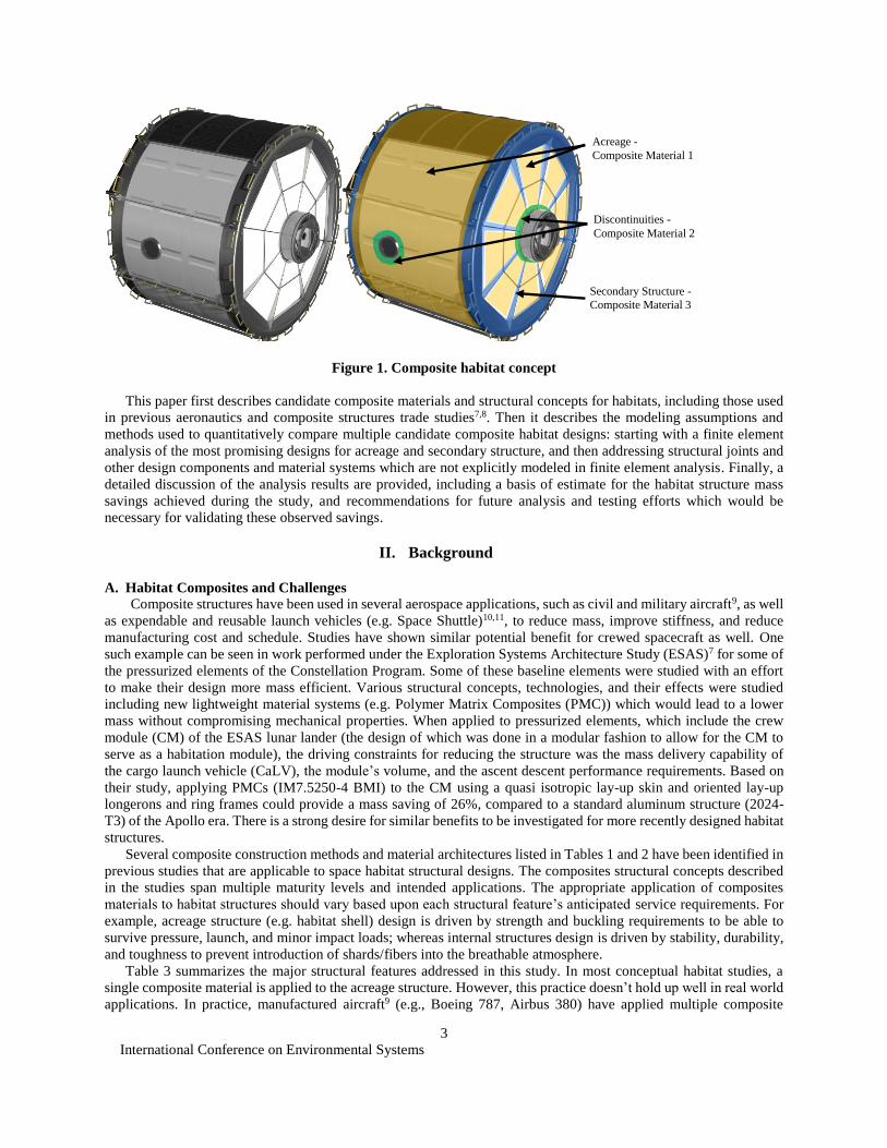
(Example: Composite Crew Module8). There is an opportunity to achieve substantial mass savings by implementing
a multiple composite habitat structure that applies different composite materials and manufacturing methods for each
part of the habitat structure (e.g., acreage, discontinuities, secondary structure, etc.) customized to its unique structural
requirements (Figure 1).
This paper documents the interim progress of a study to quantify the benefit of different composite materials and
structural concepts to reduce habitat mass and improve affordability over traditional composite and metallic
approaches. A subset of the composite structural concepts (Table 1) and material architectures (Table 2) are
qualitatively assessed against a set of figures of merit (Table 6). Then, multiple-composite habitat configurations are
generated that advantageously apply these compatible manufacturing methods to structural features of the habitat,
including large sections of uninterrupted habitat shell (i.e., acreage), joints, internal structure, and secondary structure.
These configurations are generated for conceptual MTH habitat design which are quantitatively assessed on “1)
[lower] mass … (with a target of 20% reduction in structural mass over traditional aluminum manufacturing), 2)
improv[ed] (or maintain[ed]) structural performance to reduce risk and extend life, and 3) improv[ed] manufacturing
and processing to reduce costs (will be assessed in future work)”7. The overall goal of this study is to identify
advantageous structural configurations for follow-on efforts including: 1) higher-fidelity habitat modeling efforts and
2) demonstration in element, sub-scale, and full-scale habitat hardware tests. The final results of this study will also
focus on identifying knowledge gaps for particular composite structural configurations where further research and
testing is needed.
N
International Conference on Environmental Systems
3
Figure 1. Composite habitat concept
This paper first describes candidate composite materials and structural concepts for habitats, including those used
in previous aeronautics and composite structures trade studies7,8. Then it describes the modeling assumptions and
methods used to quantitatively compare multiple candidate composite habitat designs: starting with a finite element
analysis of the most promising designs for acreage and secondary structure, and then addressing structural joints and
other design components and material systems which are not explicitly modeled in finite element analysis. Finally, a
detailed discussion of the analysis results are provided, including a basis of estimate for the habitat structure mass
savings achieved during the study, and recommendations for future analysis and testing efforts which would be
necessary for validating these observed savings.
II. Background
A. Habitat Composites and Challenges
Composite structures have been used in several aerospace applications, such as civil and military aircraft9, as well
as expendable and reusable launch vehicles (e.g. Space Shuttle)10,11, to reduce mass, improve stiffness, and reduce
manufacturing cost and schedule. Studies have shown similar potential benefit for crewed spacecraft as well. One
such example can be seen in work performed under the Exploration Systems Architecture Study (ESAS)7 for some of
the pressurized elements of the Constellation Program. Some of these baseline elements were studied with an effort
to make their design more mass efficient. Various structural concepts, technologies, and their effects were studied
including new lightweight material systems (e.g. Polymer Matrix Composites (PMC)) which would lead to a lower
mass without compromising mechanical properties. When applied to pressurized elements, which include the crew
module (CM) of the ESAS lunar lander (the design of which was done in a modular fashion to allow for the CM to
serve as a habitation module), the driving constraints for reducing the structure was the mass delivery capability of
the cargo launch vehicle (CaLV), the module’s volume, and the ascent descent performance requirements. Based on
their study, applying PMCs (IM7.5250-4 BMI) to the CM using a quasi isotropic lay-up skin and oriented lay-up
longerons and ring frames could provide a mass saving of 26%, compared to a standard aluminum structure (2024-
T3) of the Apollo era. There is a strong desire for similar benefits to be investigated for more recently designed habitat
structures.
Several composite construction methods and material architectures listed in Tables 1 and 2 have been identified in
previous studies that are applicable to space habitat structural designs. The composites structural concepts described
in the studies span multiple maturity levels and intended applications. The appropriate application of composites
materials to habitat structures should vary based upon each structural feature’s anticipated service requirements. For
example, acreage structure (e.g. habitat shell) design is driven by strength and buckling requirements to be able to
survive pressure, launch, and minor impact loads; whereas internal structures design is driven by stability, durability,
and toughness to prevent introduction of shards/fibers into the breathable atmosphere.
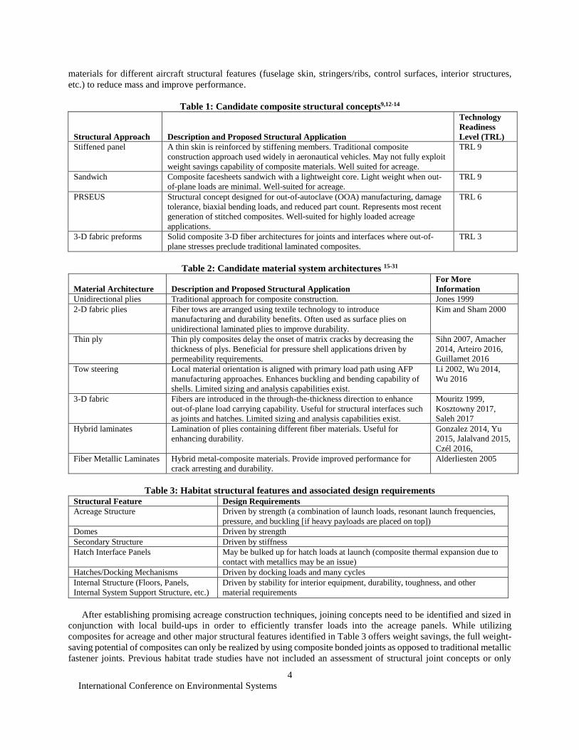
Table 3 summarizes the major structural features addressed in this study. In most conceptual habitat studies, a
single composite material is applied to the acreage structure. However, this practice doesn’t hold up well in real world
applications. In practice, manufactured aircraft9 (e.g., Boeing 787, Airbus 380) have applied multiple composite
Acreage -
Composite Material 1
Discontinuities -
Composite Material 2
Secondary Structure -
Composite Material 3
International Conference on Environmental Systems
4
materials for different aircraft structural features (fuselage skin, stringers/ribs, control surfaces, interior structures,
etc.) to reduce mass and improve performance.
Table 1: Candidate composite structural concepts9,12-14
Structural Approach Description and Proposed Structural Application
Technology
Readiness
Level (TRL)
Stiffened panel A thin skin is reinforced by stiffening members. Traditional composite
construction approach used widely in aeronautical vehicles. May not fully exploit
weight savings capability of composite materials. Well suited for acreage.
TRL 9
Sandwich Composite facesheets sandwich with a lightweight core. Light weight when out-
of-plane loads are minimal. Well-suited for acreage.
TRL 9
PRSEUS Structural concept designed for out-of-autoclave (OOA) manufacturing, damage
tolerance, biaxial bending loads, and reduced part count. Represents most recent
generation of stitched composites. Well-suited for highly loaded acreage
applications.
TRL 6
3-D fabric preforms Solid composite 3-D fiber architectures for joints and interfaces where out-of-
plane stresses preclude traditional laminated composites.
TRL 3
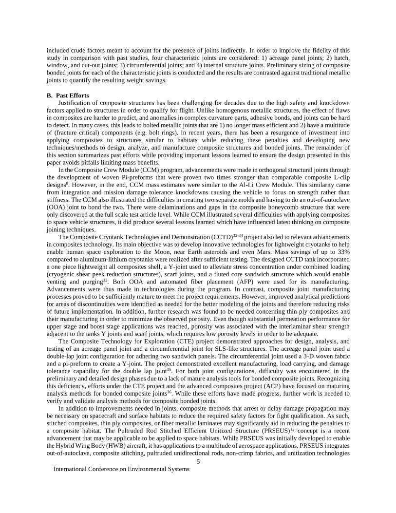
Table 2: Candidate material system architectures 15-31
Material Architecture Description and Proposed Structural Application
For More
Information
Unidirectional plies Traditional approach for composite construction. Jones 1999
2-D fabric plies Fiber tows are arranged using textile technology to introduce
manufacturing and durability benefits. Often used as surface plies on
unidirectional laminated plies to improve durability.
Kim and Sham 2000
Thin ply Thin ply composites delay the onset of matrix cracks by decreasing the
thickness of plys. Beneficial for pressure shell applications driven by
permeability requirements.
Sihn 2007, Amacher
2014, Arteiro 2016,
Guillamet 2016
Tow steering Local material orientation is aligned with primary load path using AFP
manufacturing approaches. Enhances buckling and bending capability of
shells. Limited sizing and analysis capabilities exist.
Li 2002, Wu 2014,
Wu 2016
3-D fabric Fibers are introduced in the through-the-thickness direction to enhance
out-of-plane load carrying capability. Useful for structural interfaces such
as joints and hatches. Limited sizing and analysis capabilities exist.
Mouritz 1999,
Kosztowny 2017,
Saleh 2017
Hybrid laminates Lamination of plies containing different fiber materials. Useful for
enhancing durability.
Gonzalez 2014, Yu
2015, Jalalvand 2015,
Czél 2016,
Fiber Metallic Laminates Hybrid metal-composite materials. Provide improved performance for
crack arresting and durability.
Alderliesten 2005
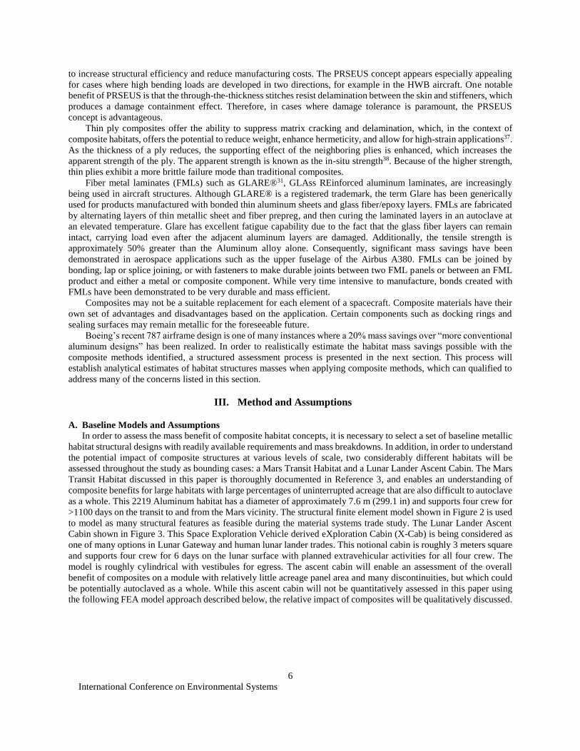
Table 3: Habitat structural features and associated design requirements
Structural Feature Design Requirements
Acreage Structure Driven by strength (a combination of launch loads, resonant launch frequencies,
pressure, and buckling [if heavy payloads are placed on top])
Domes Driven by strength
Secondary Structure Driven by stiffness
Hatch Interface Panels May be bulked up for hatch loads at launch (composite thermal expansion due to
contact with metallics may be an issue)
Hatches/Docking Mechanisms Driven by docking loads and many cycles
Internal Structure (Floors, Panels,
Internal System Support Structure, etc.)
Driven by stability for interior equipment, durability, toughness, and other
material requirements
After establishing promising acreage construction techniques, joining concepts need to be identified and sized in
conjunction with local build-ups in order to efficiently transfer loads into the acreage panels. While utilizing
composites for acreage and other major structural features identified in Table 3 offers weight savings, the full weight-
saving potential of composites can only be realized by using composite bonded joints as opposed to traditional metallic
fastener joints. Previous habitat trade studies have not included an assessment of structural joint concepts or only
International Conference on Environmental Systems
5
included crude factors meant to account for the presence of joints indirectly. In order to improve the fidelity of this
study in comparison with past studies, four characteristic joints are considered: 1) acreage panel joints; 2) hatch,
window, and cut-out joints; 3) circumferential joints; and 4) internal structure joints. Preliminary sizing of composite
bonded joints for each of the characteristic joints is conducted and the results are contrasted against traditional metallic
joints to quantify the resulting weight savings.
B. Past Efforts
Justification of composite structures has been challenging for decades due to the high safety and knockdown
factors applied to structures in order to qualify for flight. Unlike homogenous metallic structures, the effect of flaws
in composites are harder to predict, and anomalies in complex curvature parts, adhesive bonds, and joints can be hard
to detect. In many cases, this leads to bolted metallic joints that are 1) no longer mass efficient and 2) have a multitude
of (fracture critical) components (e.g. bolt rings). In recent years, there has been a resurgence of investment into
applying composites to structures similar to habitats while reducing these penalties and developing new
techniques/methods to design, analyze, and manufacture composite structures and bonded joints. The remainder of
this section summarizes past efforts while providing important lessons learned to ensure the design presented in this
paper avoids pitfalls limiting mass benefits.
In the Composite Crew Module (CCM) program, advancements were made in orthogonal structural joints through
the development of woven Pi-preforms that were proven two times stronger than comparable composite L-clip
designs8. However, in the end, CCM mass estimates were similar to the Al-Li Crew Module. This similarity came
from integration and mission damage tolerance knockdowns causing the vehicle to focus on strength rather than
stiffness. The CCM also illustrated the difficulties in creating two separate molds and having to do an out-of-autoclave
(OOA) joint to bond the two. There were delaminations and gaps in the composite honeycomb structure that were
only discovered at the full scale test article level. While CCM illustrated several difficulties with applying composites
to space vehicle structures, it did produce several lessons learned which have influenced latest thinking on composite
joining techniques.
The Composite Cryotank Technologies and Demonstration (CCTD)32-34 project also led to relevant advancements
in composites technology. Its main objective was to develop innovative technologies for lightweight cryotanks to help
enable human space exploration to the Moon, near Earth asteroids and even Mars. Mass savings of up to 33%
compared to aluminum-lithium cryotanks were realized after sufficient testing. The designed CCTD tank incorporated
a one piece lightweight all composites shell, a Y-joint used to alleviate stress concentration under combined loading
(cryogenic shear peek reduction structures), scarf joints, and a fluted core sandwich structure which would enable
venting and purging32. Both OOA and automated fiber placement (AFP) were used for its manufacturing.
Advancements were thus made in technologies during the program. In contrast, composite joint manufacturing
processes proved to be sufficiently mature to meet the project requirements. However, improved analytical predictions
for areas of discontinuities were identified as needed for the better modeling of the joints and therefore reducing risks
of future implementation. In addition, further research was found to be needed concerning thin-ply composites and
their manufacturing in order to minimize the observed porosity. Even though substantial permeation performance for
upper stage and boost stage applications was reached, porosity was associated with the interlaminar shear strength
adjacent to the tanks Y joints and scarf joints, which requires low porosity levels in order to be adequate.
The Composite Technology for Exploration (CTE) project demonstrated approaches for design, analysis, and
testing of an acreage panel joint and a circumferential joint for SLS-like structures. The acreage panel joint used a
double-lap joint configuration for adhering two sandwich panels. The circumferential joint used a 3-D woven fabric
and a pi-preform to create a Y-joint. The project demonstrated excellent manufacturing, load carrying, and damage
tolerance capability for the double lap joint35. For both joint configurations, difficulty was encountered in the
preliminary and detailed design phases due to a lack of mature analysis tools for bonded composite joints. Recognizing
this deficiency, efforts under the CTE project and the advanced composites project (ACP) have focused on maturing
analysis methods for bonded composite joints36. While these efforts have made progress, further work is needed to
verify and validate analysis methods for composite bonded joints.
In addition to improvements needed in joints, composite methods that arrest or delay damage propagation may
be necessary on spacecraft and surface habitats to reduce the required safety factors for fight qualification. As such,
stitched composites, thin ply composites, or fiber metallic laminates may significantly aid in reducing the penalties to
a composite habitat. The Pultruded Rod Stitched Efficient Unitized Structure (PRSEUS)12 concept is a recent
advancement that may be applicable to be applied to space habitats. While PRSEUS was initially developed to enable
the Hybrid Wing Body (HWB) aircraft, it has applications to a multitude of aerospace applications. PRSEUS integrates
out-of-autoclave, composite stitching, pultruded unidirectional rods, non-crimp fabrics, and unitization technologies
International Conference on Environmental Systems
6
to increase structural efficiency and reduce manufacturing costs. The PRSEUS concept appears especially appealing
for cases where high bending loads are developed in two directions, for example in the HWB aircraft. One notable
benefit of PRSEUS is that the through-the-thickness stitches resist delamination between the skin and stiffeners, which
produces a damage containment effect. Therefore, in cases where damage tolerance is paramount, the PRSEUS
concept is advantageous.
Thin ply composites offer the ability to suppress matrix cracking and delamination, which, in the context of
composite habitats, offers the potential to reduce weight, enhance hermeticity, and allow for high-strain applications37.
As the thickness of a ply reduces, the supporting effect of the neighboring plies is enhanced, which increases the
apparent strength of the ply. The apparent strength is known as the in-situ strength38. Because of the higher strength,
thin plies exhibit a more brittle failure mode than traditional composites.
Fiber metal laminates (FMLs) such as GLARE®31, GLAss REinforced aluminum laminates, are increasingly
being used in aircraft structures. Although GLARE® is a registered trademark, the term Glare has been generically
used for products manufactured with bonded thin aluminum sheets and glass fiber/epoxy layers. FMLs are fabricated
by alternating layers of thin metallic sheet and fiber prepreg, and then curing the laminated layers in an autoclave at
an elevated temperature. Glare has excellent fatigue capability due to the fact that the glass fiber layers can remain
intact, carrying load even after the adjacent aluminum layers are damaged. Additionally, the tensile strength is
approximately 50% greater than the Aluminum alloy alone. Consequently, significant mass savings have been
demonstrated in aerospace applications such as the upper fuselage of the Airbus A380. FMLs can be joined by
bonding, lap or splice joining, or with fasteners to make durable joints between two FML panels or between an FML
product and either a metal or composite component. While very time intensive to manufacture, bonds created with
FMLs have been demonstrated to be very durable and mass efficient.
Composites may not be a suitable replacement for each element of a spacecraft. Composite materials have their
own set of advantages and disadvantages based on the application. Certain components such as docking rings and
sealing surfaces may remain metallic for the foreseeable future.
Boeing’s recent 787 airframe design is one of many instances where a 20% mass savings over “more conventional
aluminum designs” has been realized. In order to realistically estimate the habitat mass savings possible with the
composite methods identified, a structured assessment process is presented in the next section. This process will
establish analytical estimates of habitat structures masses when applying composite methods, which can qualified to
address many of the concerns listed in this section.
III. Method and Assumptions
A. Baseline Models and Assumptions
In order to assess the mass benefit of composite habitat concepts, it is necessary to select a set of baseline metallic
habitat structural designs with readily available requirements and mass breakdowns. In addition, in order to understand
the potential impact of composite structures at various levels of scale, two considerably different habitats will be
assessed throughout the study as bounding cases: a Mars Transit Habitat and a Lunar Lander Ascent Cabin. The Mars
Transit Habitat discussed in this paper is thoroughly documented in Reference 3, and enables an understanding of
composite benefits for large habitats with large percentages of uninterrupted acreage that are also difficult to autoclave
as a whole. This 2219 Aluminum habitat has a diameter of approximately 7.6 m (299.1 in) and supports four crew for
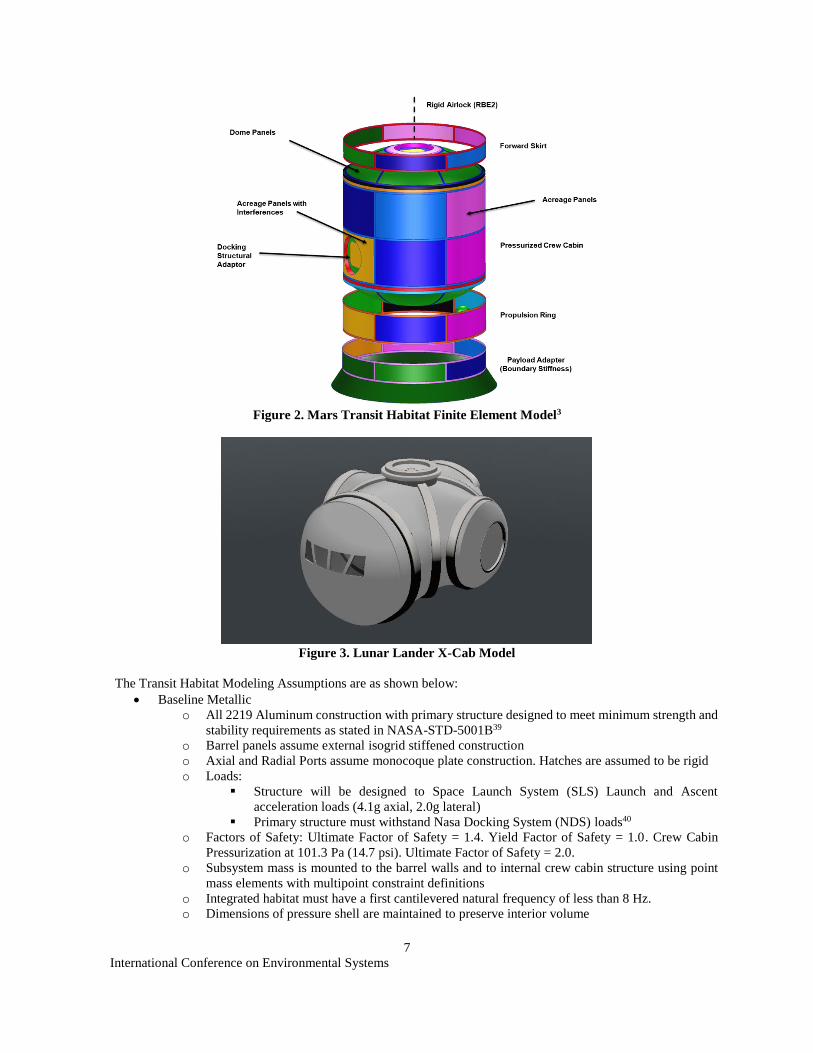
>1100 days on the transit to and from the Mars vicinity. The structural finite element model shown in Figure 2 is used
to model as many structural features as feasible during the material systems trade study. The Lunar Lander Ascent
Cabin shown in Figure 3. This Space Exploration Vehicle derived eXploration Cabin (X-Cab) is being considered as
one of many options in Lunar Gateway and human lunar lander trades. This notional cabin is roughly 3 meters square
and supports four crew for 6 days on the lunar surface with planned extravehicular activities for all four crew. The
model is roughly cylindrical with vestibules for egress. The ascent cabin will enable an assessment of the overall
benefit of composites on a module with relatively little acreage panel area and many discontinuities, but which could
be potentially autoclaved as a whole. While this ascent cabin will not be quantitatively assessed in this paper using
the following FEA model approach described below, the relative impact of composites will be qualitatively discussed.
International Conference on Environmental Systems
7
Figure 2. Mars Transit Habitat Finite Element Model3
Figure 3. Lunar Lander X-Cab Model
The Transit Habitat Modeling Assumptions are as shown below:
Baseline Metallic
o All 2219 Aluminum construction with primary structure designed to meet minimum strength and
stability requirements as stated in NASA-STD-5001B39
o Barrel panels assume external isogrid stiffened construction
o Axial and Radial Ports assume monocoque plate construction. Hatches are assumed to be rigid
o Loads:
Structure will be designed to Space Launch System (SLS) Launch and Ascent
acceleration loads (4.1g axial, 2.0g lateral)
Primary structure must withstand Nasa Docking System (NDS) loads40
o Factors of Safety: Ultimate Factor of Safety = 1.4. Yield Factor of Safety = 1.0. Crew Cabin
Pressurization at 101.3 Pa (14.7 psi). Ultimate Factor of Safety = 2.0.
o Subsystem mass is mounted to the barrel walls and to internal crew cabin structure using point
mass elements with multipoint constraint definitions
o Integrated habitat must have a first cantilevered natural frequency of less than 8 Hz.
o Dimensions of pressure shell are maintained to preserve interior volume
NOTIONAL
International Conference on Environmental Systems
8
B. HyperSizer Composite Mass Analysis Process
A finite element model (FEM) of the MTH is used to determine the effect of structural design choices and various
materials systems on habitat dry weight. For the baseline metallic habitat concept, the primary and secondary structure
is sized using a HyperSizer/NASTRAN/PATRAN structural model approach similar to the approach used in Ref. 2.
To simplify the analysis and ensure only the effects of the habitat structures are traded, the model was simplified to
isolate only the habitat structure itself (less any payload adaptors, or propulsion stages). The loads from these other
structures are included in the analyses, but not reported in the structural mass comparisons.
After the reduced baseline metallic habitat masses are assessed and documented, the material and composite
structural concept trades are performed systematically, sequentially, and independently. A partial test matrix of
composite materials/structural concepts assessed for the MTH structural features is shown in Table 4. Only those
combinations identified by discipline experts as sufficiently mature, feasible, and advantageous are assessed. Initially,
each habitat structural feature is assessed independently to identify the best candidates for habitat structural mass
reduction. Thus, the set of trades is intended to be exploratory, not comprehensive.
Table 4: Composite habitat analysis matrix
Stiffened panel Sandwich Monolithic
Acreage panels x x
Dome panels x x
Floors x x
Internal columns x
For each analyzed case, HyperSizer is used to make slight adjustments to thicknesses and structural design to
optimize structural performance to service requirements. Details of the model and sizing assumptions are provided in
the following two sections.
C. Mars Transit Habitat Model
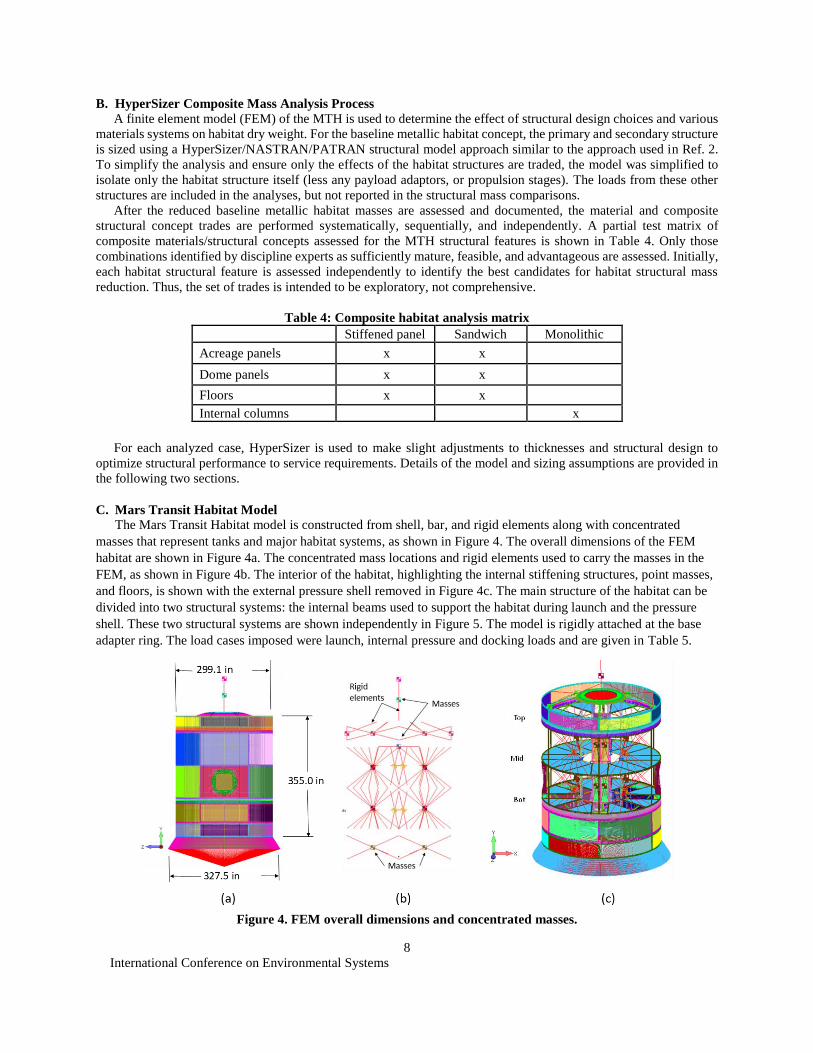
The Mars Transit Habitat model is constructed from shell, bar, and rigid elements along with concentrated
masses that represent tanks and major habitat systems, as shown in Figure 4. The overall dimensions of the FEM
habitat are shown in Figure 4a. The concentrated mass locations and rigid elements used to carry the masses in the
FEM, as shown in Figure 4b. The interior of the habitat, highlighting the internal stiffening structures, point masses,
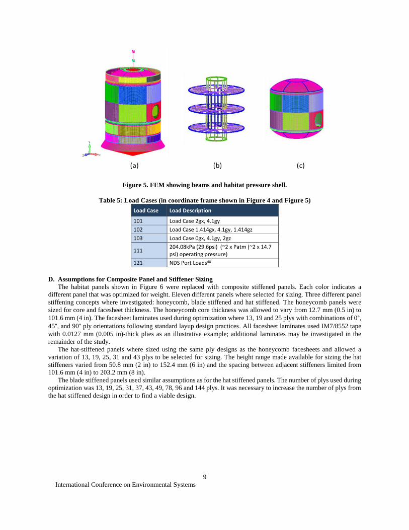
and floors, is shown with the external pressure shell removed in Figure 4c. The main structure of the habitat can be
divided into two structural systems: the internal beams used to support the habitat during launch and the pressure
shell. These two structural systems are shown independently in Figure 5. The model is rigidly attached at the base
adapter ring. The load cases imposed were launch, internal pressure and docking loads and are given in Table 5.
Figure 4. FEM overall dimensions and concentrated masses.
International Conference on Environmental Systems
9
Figure 5. FEM showing beams and habitat pressure shell.
Table 5: Load Cases (in coordinate frame shown in Figure 4 and Figure 5)
Load Case Load Description
101 Load Case 2gx, 4.1gy
102 Load Case 1.414gx, 4.1gy, 1.414gz
103 Load Case 0gx, 4.1gy, 2gz
111 204.08kPa (29.6psi) (~2 x Patm (~2 x 14.7 psi) operating pressure)
121 NDS Port Loads40
D. Assumptions for Composite Panel and Stiffener Sizing
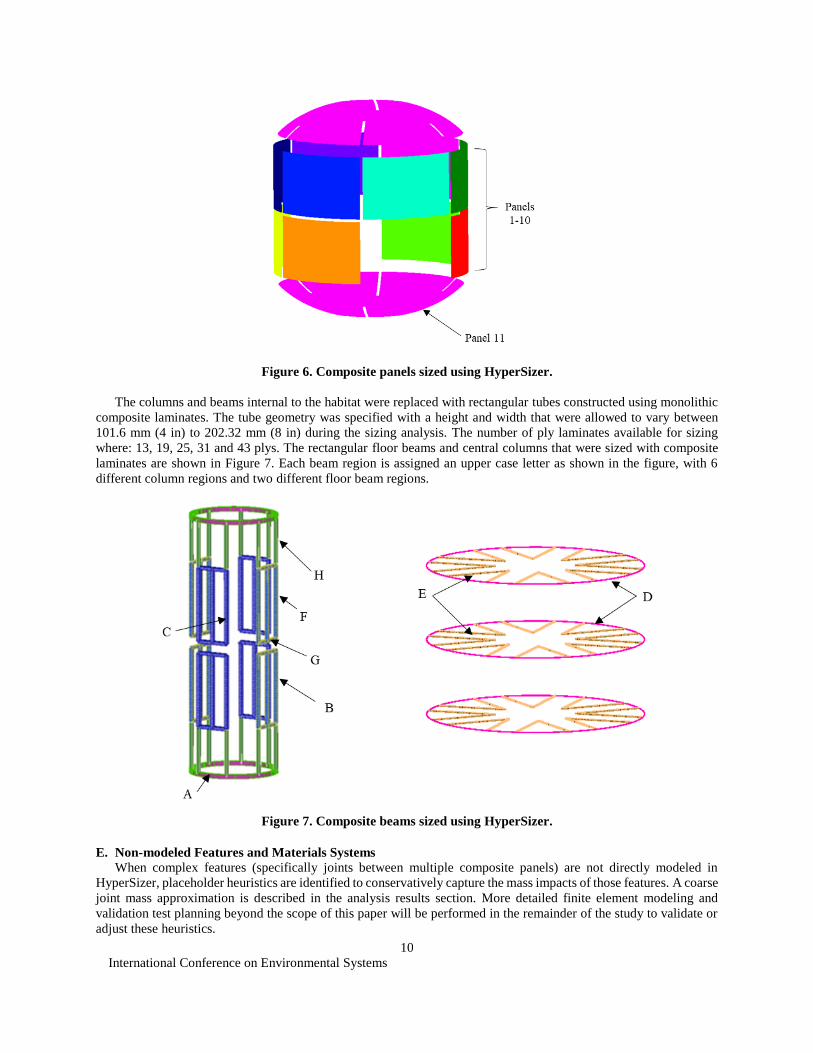
The habitat panels shown in Figure 6 were replaced with composite stiffened panels. Each color indicates a
different panel that was optimized for weight. Eleven different panels where selected for sizing. Three different panel
stiffening concepts where investigated: honeycomb, blade stiffened and hat stiffened. The honeycomb panels were
sized for core and facesheet thickness. The honeycomb core thickness was allowed to vary from 12.7 mm (0.5 in) to
101.6 mm (4 in). The facesheet laminates used during optimization where 13, 19 and 25 plys with combinations of 0°, 45°, and 90° ply orientations following standard layup design practices. All facesheet laminates used IM7/8552 tape
with 0.0127 mm (0.005 in)-thick plies as an illustrative example; additional laminates may be investigated in the
remainder of the study.
The hat-stiffened panels where sized using the same ply designs as the honeycomb facesheets and allowed a
variation of 13, 19, 25, 31 and 43 plys to be selected for sizing. The height range made available for sizing the hat
stiffeners varied from 50.8 mm (2 in) to 152.4 mm (6 in) and the spacing between adjacent stiffeners limited from
101.6 mm (4 in) to 203.2 mm (8 in).
The blade stiffened panels used similar assumptions as for the hat stiffened panels. The number of plys used during
optimization was 13, 19, 25, 31, 37, 43, 49, 78, 96 and 144 plys. It was necessary to increase the number of plys from
the hat stiffened design in order to find a viable design.
International Conference on Environmental Systems
10
Figure 6. Composite panels sized using HyperSizer.
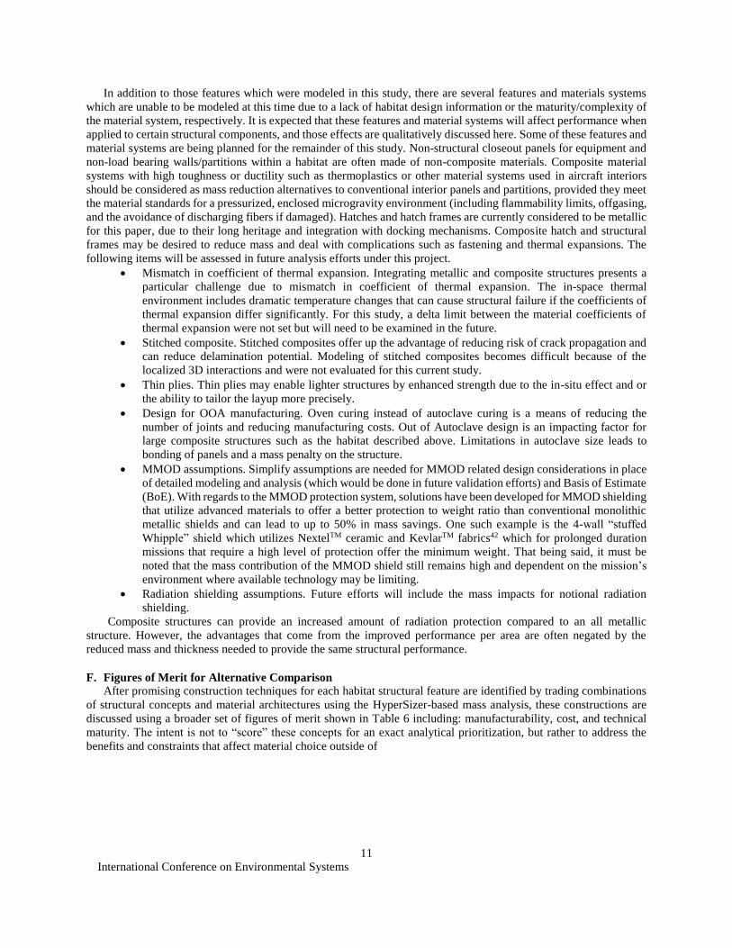
The columns and beams internal to the habitat were replaced with rectangular tubes constructed using monolithic
composite laminates. The tube geometry was specified with a height and width that were allowed to vary between
101.6 mm (4 in) to 202.32 mm (8 in) during the sizing analysis. The number of ply laminates available for sizing
where: 13, 19, 25, 31 and 43 plys. The rectangular floor beams and central columns that were sized with composite
laminates are shown in Figure 7. Each beam region is assigned an upper case letter as shown in the figure, with 6
different column regions and two different floor beam regions.
Figure 7. Composite beams sized using HyperSizer.
E. Non-modeled Features and Materials Systems
When complex features (specifically joints between multiple composite panels) are not directly modeled in
HyperSizer, placeholder heuristics are identified to conservatively capture the mass impacts of those features. A coarse
joint mass approximation is described in the analysis results section. More detailed finite element modeling and
validation test planning beyond the scope of this paper will be performed in the remainder of the study to validate or
adjust these heuristics.
International Conference on Environmental Systems
11
In addition to those features which were modeled in this study, there are several features and materials systems
which are unable to be modeled at this time due to a lack of habitat design information or the maturity/complexity of
the material system, respectively. It is expected that these features and material systems will affect performance when
applied to certain structural components, and those effects are qualitatively discussed here. Some of these features and
material systems are being planned for the remainder of this study. Non-structural closeout panels for equipment and
non-load bearing walls/partitions within a habitat are often made of non-composite materials. Composite material
systems with high toughness or ductility such as thermoplastics or other material systems used in aircraft interiors
should be considered as mass reduction alternatives to conventional interior panels and partitions, provided they meet
the material standards for a pressurized, enclosed microgravity environment (including flammability limits, offgasing,
and the avoidance of discharging fibers if damaged). Hatches and hatch frames are currently considered to be metallic
for this paper, due to their long heritage and integration with docking mechanisms. Composite hatch and structural
frames may be desired to reduce mass and deal with complications such as fastening and thermal expansions. The
following items will be assessed in future analysis efforts under this project.
Mismatch in coefficient of thermal expansion. Integrating metallic and composite structures presents a
particular challenge due to mismatch in coefficient of thermal expansion. The in-space thermal
environment includes dramatic temperature changes that can cause structural failure if the coefficients of
thermal expansion differ significantly. For this study, a delta limit between the material coefficients of
thermal expansion were not set but will need to be examined in the future.
Stitched composite. Stitched composites offer up the advantage of reducing risk of crack propagation and
can reduce delamination potential. Modeling of stitched composites becomes difficult because of the
localized 3D interactions and were not evaluated for this current study.
Thin plies. Thin plies may enable lighter structures by enhanced strength due to the in-situ effect and or
the ability to tailor the layup more precisely.
Design for OOA manufacturing. Oven curing instead of autoclave curing is a means of reducing the
number of joints and reducing manufacturing costs. Out of Autoclave design is an impacting factor for
large composite structures such as the habitat described above. Limitations in autoclave size leads to
bonding of panels and a mass penalty on the structure.
MMOD assumptions. Simplify assumptions are needed for MMOD related design considerations in place
of detailed modeling and analysis (which would be done in future validation efforts) and Basis of Estimate
(BoE). With regards to the MMOD protection system, solutions have been developed for MMOD shielding
that utilize advanced materials to offer a better protection to weight ratio than conventional monolithic
metallic shields and can lead to up to 50% in mass savings. One such example is the 4-wall “stuffed
Whipple” shield which utilizes NextelTM ceramic and KevlarTM fabrics42 which for prolonged duration
missions that require a high level of protection offer the minimum weight. That being said, it must be
noted that the mass contribution of the MMOD shield still remains high and dependent on the mission’s
environment where available technology may be limiting.
Radiation shielding assumptions. Future efforts will include the mass impacts for notional radiation
shielding.
Composite structures can provide an increased amount of radiation protection compared to an all metallic
structure. However, the advantages that come from the improved performance per area are often negated by the
reduced mass and thickness needed to provide the same structural performance.
F. Figures of Merit for Alternative Comparison
After promising construction techniques for each habitat structural feature are identified by trading combinations
of structural concepts and material architectures using the HyperSizer-based mass analysis, these constructions are
discussed using a broader set of figures of merit shown in Table 6 including: manufacturability, cost, and technical
maturity. The intent is not to “score” these concepts for an exact analytical prioritization, but rather to address the
benefits and constraints that affect material choice outside of
International Conference on Environmental Systems
12
Table 6: Habitat Composite Structures Figures of Merit
Figure of Merit Measurement Method
Mass Reduction HyperSizer Analysis and Heuristic
Methods
Manufacturability Anecdotal
Cost Parametric Cost Estimation (Future Work)
Technical Maturity NASA TRL Scale
IV. Analyses Results
A. Mars Transit Habitat Metallic vs. Composite Comparison
This section describes the results of the composite sizing using the HyperSizer modeling approach described in
Section III. While detailed modeling for the metallic baseline is not shown, they are provided towards the end of this
section for purposes of comparison with the optimized composite structural designs.
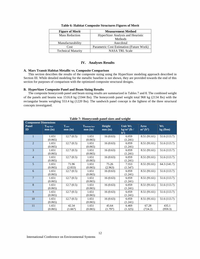
B. HyperSizer Composite Panel and Beam Sizing Results
The composite honeycomb panel and beam sizing results are summarized in Tables 7 and 8. The combined weight
of the panels and beams was 1516.8 kg (3344 lbs). The honeycomb panel weight total 968 kg (2134 lbs) with the
rectangular beams weighing 553.4 kg (1220 lbs). The sandwich panel concept is the lightest of the three structural
concepts investigated.
Table 7: Honeycomb panel sizes and weight
Component Dimensions
Panel
ID
Ttop face
mm (in)
Tcore
mm (in)
Tbottom face
mm (in)
Height
mm (in)
Unit Wt.
kg/m2 (lb /
ft2)
Area
m2 (ft2)
Wt.
kg (lbm)
1 1.651
(0.065)
12.7 (0.5) 1.651
(0.065)
16 (0.63) 6.059
(1.241)
8.51 (91.61) 51.6 (113.7)
2 1.651
(0.065)
12.7 (0.5) 1.651
(0.065)
16 (0.63) 6.059
(1.241)
8.51 (91.61) 51.6 (113.7)
3 1.651
(0.065)
12.7 (0.5) 1.651
(0.065)
16 (0.63) 6.059
(1.241)
8.51 (91.61) 51.6 (113.7)
4 1.651
(0.065)
12.7 (0.5) 1.651
(0.065)
16 (0.63) 6.059
(1.241)
8.51 (91.61) 51.6 (113.7)
5 1.651
(0.065)
71.96
(2.833)
1.651
(0.065)
75.26
(2.963)
7.553
(1.547)
8.51 (91.61) 64.3 (141.7)
6 1.651
(0.065)
12.7 (0.5) 1.651
(0.065)
16 (0.63) 6.059
(1.241)
8.51 (91.61) 51.6 (113.7)
7 1.651
(0.065)
12.7 (0.5) 1.651
(0.065)
16 (0.63) 6.059
(1.241)
8.51 (91.61) 51.6 (113.7)
8 1.651
(0.065)
12.7 (0.5) 1.651
(0.065)
16 (0.63) 6.059
(1.241)
8.51 (91.61) 51.6 (113.7)
9 1.651
(0.065)
12.7 (0.5) 1.651
(0.065)
16 (0.63) 6.059
(1.241)
8.51 (91.61) 51.6 (113.7)
10 1.651
(0.065)
12.7 (0.5) 1.651
(0.065)
16 (0.63) 6.059
(1.241)
8.51 (91.61) 51.6 (113.7)
11 1.651
(0.065)
42.34
(1.667)
1.651
(0.065)
45.64
(1.797)
6.469
(1.325)
67.28
(724.2)
435.1
(959.3)
International Conference on Environmental Systems
13
Table 8: Honeycomb panel sizing summary Honeycomb Summary
Weight Total kg (lbm) 1516.9 (3344)
Beam, Unit Weight kg/m (lb/ ft) 0.162 (1.175)
Beam, Total Length m (ft) 316.38 (1038)
Beam, Total Weight kg (lbm) 553.4 (1220)
Panel, Unit Weight kg/m (lb/ft2) 6.323 (1.295)
Panel, Total Area m2 (ft2) 152.36 (1640)
Panel, Total Weight kg (lbm) 963.4 (2124)
Figure 9. Honeycomb geometry.
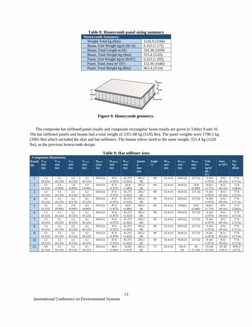
The composite hat stiffened panel results and composite rectangular beam results are given in Tables 9 and 10.
The hat stiffened panels and beams had a total weight of 2351.88 kg (5185 lbs). The panel weights were 1798.5 kg
(3965 lbs) which included the skin and hat stiffeners. The beams where sized to the same weight, 553.4 kg (1220
lbs), as the previous honeycomb design.
Table 9: Hat stiffener sizes Component Dimensions
Panel
ID
Tskin
mm
(in)
Tweb
mm
(in)
Tfoot
mm
(in)
Tcrown
mm
(in)
Hpanel
(mm
(in)
Hstiffener
mm
(in)
Hweb
mm
(in)
Spacin
g
mm
(in)
Angle
(°)
Wfoot
mm
(in)
Wcrown
mm
(in)
Wopen
mm
(in)
Unit
Wt.
kg/m2
(lb /
ft2)
Area
m2 (ft2)
Wt.
Kg
(lbm)
1 3.2
(0.125)
3.2
(0.125)
3.2
(0.125)
3.2
(0.125)
50.8 (2) 47.6
(1.875)
41.275
(1.625)
203.2
(8)
90 25.4 (1) 50.8 (2) 127 (5) 9.145
(1.873)
8.51
(91.61)
77.8
(171.6)
2 3.2
(0.125)
2.4
(0.095)
2.4
(0.095)
2.4
(0.095)
50.8 (2) 47.6
(1.875)
42.8
(1.685)
203.2
(8)
60 25.4 (1) 50.8 (2) 74.8
(2.945)
8.451
(1.731)
8.51
(91.61)
71.9
(158.6)
3 3.2
(0.125)
3.2
(0.125)
3.2
(0.125)
3.2
(0.125)
50.8 (2) 47.6
(1.875)
41.275
(1.625)
203.2
(8)
90 25.4 (1) 50.8 (2) 127 (5) 9.145
(1.873)
8.51
(91.61)
77.8
(171.6)
4 3.2
(0.125)
3.2
(0.125)
3.2
(0.125)
3.2
(0.125)
50.8 (2) 47.6
(1.875)
41.275
(1.625)
203.2
(8)
90 25.4 (1) 50.8 (2) 127 (5) 9.145
(1.873)
8.51
(91.61)
77.8
(171.6)
5 3.2
(0.125)
2.4
(0.095)
2.4
(0.095)
2.4
(0.095)
50.8 (2) 47.6
(1.875)
42.8
(1.685)
203.2
(8)
60 25.4 (1) 50.8(2) 74.8
(2.945)
8.451
(1.731)
8.51
(91.61)
71.9
(158.6)
6 3.2
(0.125)
3.2
(0.125)
3.2
(0.125)
3.2
(0.125)
50.8 (2) 47.6
(1.875)
41.275
(1.625)
203.2
(8)
90 25.4 (1) 50.8 (2) 127 (5) 9.145
(1.873)
8.51
(91.61)
77.8
(171.6)
7 3.2
(0.125)
3.2
(0.125)
3.2
(0.125)
3.2
(0.125)
50.8 (2) 47.6
(1.875)
41.275
(1.625)
203.2
(8)
90 25.4 (1) 50.8 (2) 127 (5) 9.145
(1.873)
8.51
(91.61)
77.8
(171.6)
8 3.2
(0.125)
3.2
(0.125)
3.2
(0.125)
3.2
(0.125)
50.8 (2) 47.6
(1.875)
41.275
(1.625)
203.2
(8)
90 25.4 (1) 50.8 (2) 127 (5) 9.145
(1.873)
8.51
(91.61)
77.8
(171.6)
9 3.2
(0.125)
3.2
(0.125)
3.2
(0.125)
3.2
(0.125)
50.8 (2) 47.6
(1.875)
41.275
(1.625)
203.2
(8)
90 25.4 (1) 50.8 (2) 127 (5) 9.145
(1.873)
8.51
(91.61)
77.8
(171.6)
10 3.2
(0.125)
3.2
(0.125)
3.2
(0.125)
3.2
(0.125)
50.8 (2) 47.6
(1.875)
41.275
(1.625)
203.2
(8)
90 25.4 (1) 50.8 (2) 127 (5) 9.145
(1.873)
8.51
(91.61)
77.8
(171.6)
11 3.9
(0.155)
5.5
(0.215)
5.5
(0.215)
5.5
(0.215)
50.8 (2) 46.9
(1.845)
35.94
(1.415)
203.2
(8)
75 25.4 (1) 101.6
(4)
54
(2.126)
15.341
(3.142)
67.28
(724.2)
1031.9
(2275)
International Conference on Environmental Systems
14
Table 10: Hat stiffened sizing summary Hat Summary
Weight Total kg (lbm) 2351.9 (5185)
Beam, Unit Weight kg/m(lb / ft) 0.162 (1.175)
Beam, Total Length m (ft) 316.38 (1038)
Beam, Total Weight kg (lbm) 553.4 (1220)
Panel, Unit Weight kg/m2 (lb / ft2) 11.8 (2.417)
Panel, Total Area m2(ft2) 152.36 (1640)
Panel, Total Weight kg (lbm) 1798.5 (3965)
Figure 10. Hat stiffener geometry.
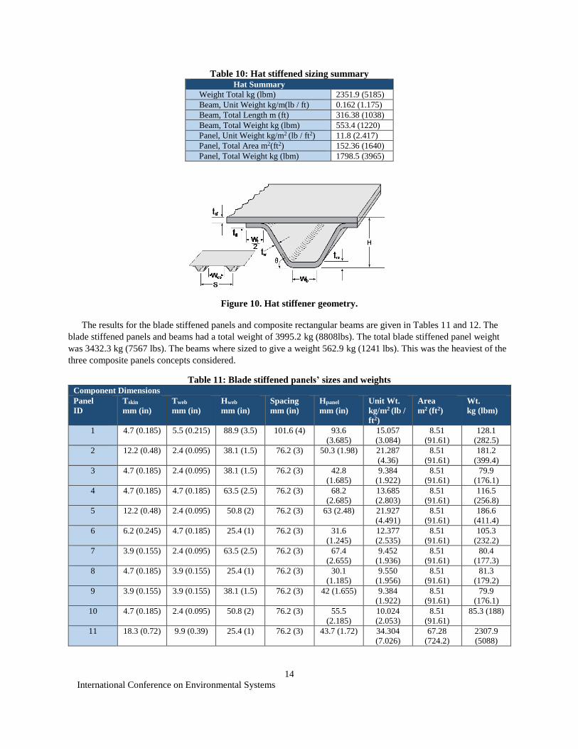
The results for the blade stiffened panels and composite rectangular beams are given in Tables 11 and 12. The
blade stiffened panels and beams had a total weight of 3995.2 kg (8808lbs). The total blade stiffened panel weight
was 3432.3 kg (7567 lbs). The beams where sized to give a weight 562.9 kg (1241 lbs). This was the heaviest of the
three composite panels concepts considered.
Table 11: Blade stiffened panels’ sizes and weights Component Dimensions
Panel
ID
Tskin
mm (in)
Tweb
mm (in)
Hweb
mm (in)
Spacing
mm (in)
Hpanel
mm (in)
Unit Wt.
kg/m2 (lb /
ft2)
Area
m2 (ft2)
Wt.
kg (lbm)
1 4.7 (0.185) 5.5 (0.215) 88.9 (3.5) 101.6 (4) 93.6
(3.685)
15.057
(3.084)
8.51
(91.61)
128.1
(282.5)
2 12.2 (0.48) 2.4 (0.095) 38.1 (1.5) 76.2 (3) 50.3 (1.98) 21.287
(4.36)
8.51
(91.61)
181.2
(399.4)
3 4.7 (0.185) 2.4 (0.095) 38.1 (1.5) 76.2 (3) 42.8
(1.685)
9.384
(1.922)
8.51
(91.61)
79.9
(176.1)
4 4.7 (0.185) 4.7 (0.185) 63.5 (2.5) 76.2 (3) 68.2
(2.685)
13.685
(2.803)
8.51
(91.61)
116.5
(256.8)
5 12.2 (0.48) 2.4 (0.095) 50.8 (2) 76.2 (3) 63 (2.48) 21.927
(4.491)
8.51
(91.61)
186.6
(411.4)
6 6.2 (0.245) 4.7 (0.185) 25.4 (1) 76.2 (3) 31.6
(1.245)
12.377
(2.535)
8.51
(91.61)
105.3
(232.2)
7 3.9 (0.155) 2.4 (0.095) 63.5 (2.5) 76.2 (3) 67.4
(2.655)
9.452
(1.936)
8.51
(91.61)
80.4
(177.3)
8 4.7 (0.185) 3.9 (0.155) 25.4 (1) 76.2 (3) 30.1
(1.185)
9.550
(1.956)
8.51
(91.61)
81.3
(179.2)
9 3.9 (0.155) 3.9 (0.155) 38.1 (1.5) 76.2 (3) 42 (1.655) 9.384
(1.922)
8.51
(91.61)
79.9
(176.1)
10 4.7 (0.185) 2.4 (0.095) 50.8 (2) 76.2 (3) 55.5
(2.185)
10.024
(2.053)
8.51
(91.61)
85.3 (188)
11 18.3 (0.72) 9.9 (0.39) 25.4 (1) 76.2 (3) 43.7 (1.72) 34.304
(7.026)
67.28
(724.2)
2307.9
(5088)
International Conference on Environmental Systems
15
Table 12: Blade stiffened sizing summary Blade Summary
Weight Total kg (lbm) 3995.2 (8808)
Beam, Unit Weight kg/m (lb / ft) 0.165 (1.195)
Beam, Total Length m (ft) 316.38 (1038)
Beam, Total Weight kg (lbm) 562.9 (1241)
Panel, Unit Weight kg/m2(lb / ft2) 22.523 (4.613)
Panel, Total Area m2(ft2) 152.36 (1640)
Panel, Total Weight kg (lbm) 3432.3 (7567)
Figure 11. Blade stiffened geometry
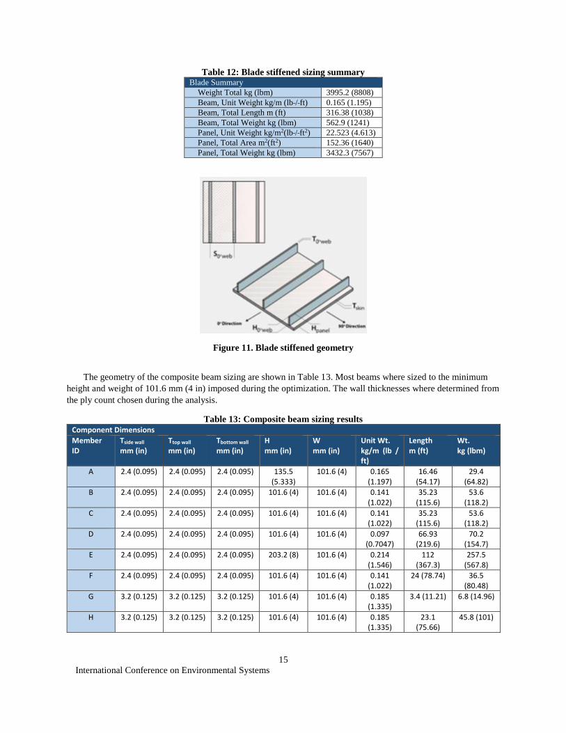
The geometry of the composite beam sizing are shown in Table 13. Most beams where sized to the minimum
height and weight of 101.6 mm (4 in) imposed during the optimization. The wall thicknesses where determined from
the ply count chosen during the analysis.
Table 13: Composite beam sizing results
Component Dimensions
Member ID
Tside wall mm (in)
Ttop wall mm (in)
Tbottom wall mm (in)
H mm (in)
W mm (in)
Unit Wt. kg/m (lb / ft)
Length m (ft)
Wt. kg (lbm)
A 2.4 (0.095) 2.4 (0.095) 2.4 (0.095) 135.5 (5.333)
101.6 (4) 0.165 (1.197)
16.46 (54.17)
29.4 (64.82)
B 2.4 (0.095) 2.4 (0.095) 2.4 (0.095) 101.6 (4) 101.6 (4) 0.141 (1.022)
35.23 (115.6)
53.6 (118.2)
C 2.4 (0.095) 2.4 (0.095) 2.4 (0.095) 101.6 (4) 101.6 (4) 0.141 (1.022)
35.23 (115.6)
53.6 (118.2)
D 2.4 (0.095) 2.4 (0.095) 2.4 (0.095) 101.6 (4) 101.6 (4) 0.097 (0.7047)
66.93 (219.6)
70.2 (154.7)
E 2.4 (0.095) 2.4 (0.095) 2.4 (0.095) 203.2 (8) 101.6 (4) 0.214 (1.546)
112 (367.3)
257.5 (567.8)
F 2.4 (0.095) 2.4 (0.095) 2.4 (0.095) 101.6 (4) 101.6 (4) 0.141 (1.022)
24 (78.74) 36.5 (80.48)
G 3.2 (0.125) 3.2 (0.125) 3.2 (0.125) 101.6 (4) 101.6 (4) 0.185 (1.335)
3.4 (11.21) 6.8 (14.96)
H 3.2 (0.125) 3.2 (0.125) 3.2 (0.125) 101.6 (4) 101.6 (4) 0.185 (1.335)
23.1 (75.66)
45.8 (101)
International Conference on Environmental Systems
16
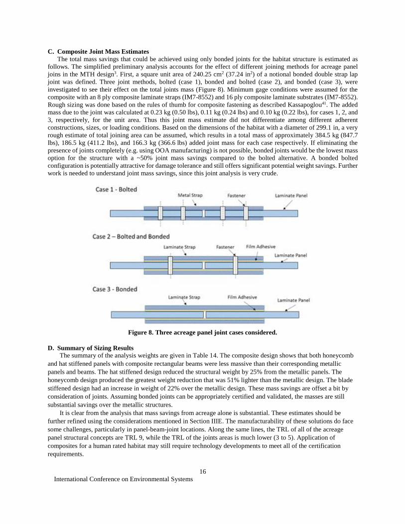
C. Composite Joint Mass Estimates
The total mass savings that could be achieved using only bonded joints for the habitat structure is estimated as
follows. The simplified preliminary analysis accounts for the effect of different joining methods for acreage panel
joins in the MTH design3. First, a square unit area of 240.25 cm2 (37.24 in2) of a notional bonded double strap lap
joint was defined. Three joint methods, bolted (case 1), bonded and bolted (case 2), and bonded (case 3), were
investigated to see their effect on the total joints mass (Figure 8). Minimum gage conditions were assumed for the
composite with an 8 ply composite laminate straps (IM7-8552) and 16 ply composite laminate substrates (IM7-8552).
Rough sizing was done based on the rules of thumb for composite fastening as described Kassapoglou41. The added
mass due to the joint was calculated at 0.23 kg (0.50 lbs), 0.11 kg (0.24 lbs) and 0.10 kg (0.22 lbs), for cases 1, 2, and
3, respectively, for the unit area. Thus this joint mass estimate did not differentiate among different adherent
constructions, sizes, or loading conditions. Based on the dimensions of the habitat with a diameter of 299.1 in, a very
rough estimate of total joining area can be assumed, which results in a total mass of approximately 384.5 kg (847.7
lbs), 186.5 kg (411.2 lbs), and 166.3 kg (366.6 lbs) added joint mass for each case respectively. If eliminating the
presence of joints completely (e.g. using OOA manufacturing) is not possible, bonded joints would be the lowest mass
option for the structure with a ~50% joint mass savings compared to the bolted alternative. A bonded bolted
configuration is potentially attractive for damage tolerance and still offers significant potential weight savings. Further
work is needed to understand joint mass savings, since this joint analysis is very crude.
Figure 8. Three acreage panel joint cases considered.
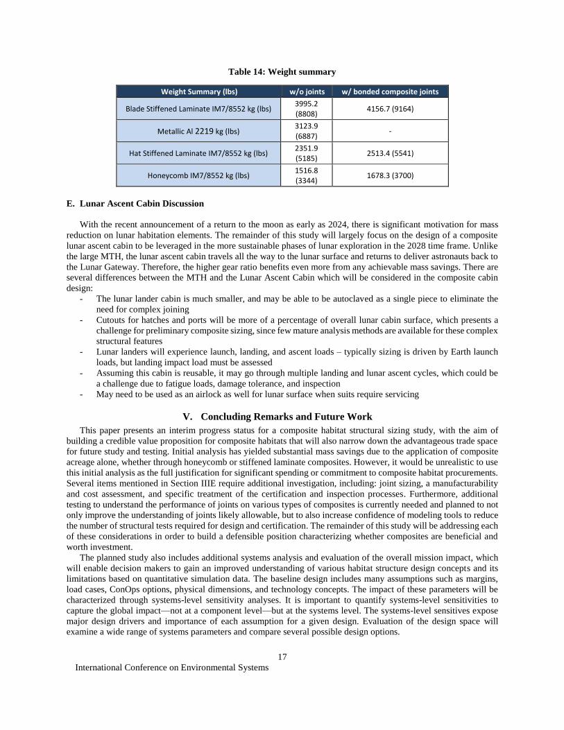
D. Summary of Sizing Results
The summary of the analysis weights are given in Table 14. The composite design shows that both honeycomb
and hat stiffened panels with composite rectangular beams were less massive than their corresponding metallic
panels and beams. The hat stiffened design reduced the structural weight by 25% from the metallic panels. The
honeycomb design produced the greatest weight reduction that was 51% lighter than the metallic design. The blade
stiffened design had an increase in weight of 22% over the metallic design. These mass savings are offset a bit by
consideration of joints. Assuming bonded joints can be appropriately certified and validated, the masses are still
substantial savings over the metallic structures.
It is clear from the analysis that mass savings from acreage alone is substantial. These estimates should be
further refined using the considerations mentioned in Section IIIE. The manufacturability of these solutions do face
some challenges, particularly in panel-beam-joint locations. Along the same lines, the TRL of all of the acreage
panel structural concepts are TRL 9, while the TRL of the joints areas is much lower (3 to 5). Application of
composites for a human rated habitat may still require technology developments to meet all of the certification
requirements.
International Conference on Environmental Systems
17
Table 14: Weight summary
Weight Summary (lbs) w/o joints w/ bonded composite joints
Blade Stiffened Laminate IM7/8552 kg (lbs) 3995.2 (8808)
4156.7 (9164)
Metallic Al 2219 kg (lbs) 3123.9 (6887)
-
Hat Stiffened Laminate IM7/8552 kg (lbs) 2351.9 (5185)
2513.4 (5541)
Honeycomb IM7/8552 kg (lbs) 1516.8 (3344)
1678.3 (3700)
E. Lunar Ascent Cabin Discussion
With the recent announcement of a return to the moon as early as 2024, there is significant motivation for mass
reduction on lunar habitation elements. The remainder of this study will largely focus on the design of a composite
lunar ascent cabin to be leveraged in the more sustainable phases of lunar exploration in the 2028 time frame. Unlike
the large MTH, the lunar ascent cabin travels all the way to the lunar surface and returns to deliver astronauts back to
the Lunar Gateway. Therefore, the higher gear ratio benefits even more from any achievable mass savings. There are
several differences between the MTH and the Lunar Ascent Cabin which will be considered in the composite cabin
design:
- The lunar lander cabin is much smaller, and may be able to be autoclaved as a single piece to eliminate the
need for complex joining
- Cutouts for hatches and ports will be more of a percentage of overall lunar cabin surface, which presents a
challenge for preliminary composite sizing, since few mature analysis methods are available for these complex
structural features
- Lunar landers will experience launch, landing, and ascent loads – typically sizing is driven by Earth launch
loads, but landing impact load must be assessed
- Assuming this cabin is reusable, it may go through multiple landing and lunar ascent cycles, which could be
a challenge due to fatigue loads, damage tolerance, and inspection
- May need to be used as an airlock as well for lunar surface when suits require servicing
V. Concluding Remarks and Future Work
This paper presents an interim progress status for a composite habitat structural sizing study, with the aim of
building a credible value proposition for composite habitats that will also narrow down the advantageous trade space
for future study and testing. Initial analysis has yielded substantial mass savings due to the application of composite
acreage alone, whether through honeycomb or stiffened laminate composites. However, it would be unrealistic to use
this initial analysis as the full justification for significant spending or commitment to composite habitat procurements.
Several items mentioned in Section IIIE require additional investigation, including: joint sizing, a manufacturability
and cost assessment, and specific treatment of the certification and inspection processes. Furthermore, additional
testing to understand the performance of joints on various types of composites is currently needed and planned to not
only improve the understanding of joints likely allowable, but to also increase confidence of modeling tools to reduce
the number of structural tests required for design and certification. The remainder of this study will be addressing each
of these considerations in order to build a defensible position characterizing whether composites are beneficial and
worth investment.
The planned study also includes additional systems analysis and evaluation of the overall mission impact, which
will enable decision makers to gain an improved understanding of various habitat structure design concepts and its
limitations based on quantitative simulation data. The baseline design includes many assumptions such as margins,
load cases, ConOps options, physical dimensions, and technology concepts. The impact of these parameters will be
characterized through systems-level sensitivity analyses. It is important to quantify systems-level sensitivities to
capture the global impact—not at a component level—but at the systems level. The systems-level sensitives expose
major design drivers and importance of each assumption for a given design. Evaluation of the design space will
examine a wide range of systems parameters and compare several possible design options.
International Conference on Environmental Systems
18
Acknowledgments
The authors would like to thank: Wade Jackson for discussions on past program experience with composites, David
Smitherman and Jay Garcia for access to the transit habitat finite element model, and the Langley Technology Council
for funding this study.
References
1Simon, M. A., et al., “Evolvable Mars Campaign Long Duration Habitation Strategies: Architectural Approaches to Enable
Human Exploration Missions (AIAA 2015-4514),” AIAA SPACE 2015 Conference and Exposition, Pasadena, CA, 2015. 2Simon, M. A., et al., “NASA’s Advanced Exploration Systems Mars Transit Habitat Refinement Point of Departure Design,”
2017 IEEE Aerospace Conference, Big Sky, MT, 2017, pp. 1-34. doi: 10.1109/AERO.2017.7943662 3Polsgrove, T. P., Waggoner, J. D., Smitherman, D. V., Percy, T. K., and Howard, R. L., “Transit Habitat Design for Mars
Exploration (AIAA-2018-5143),” AIAA SPACE 2018 Conference and Exposition, Orlando, FL, 2018. 4Hufenbach, B., Laurini, K., Satoh, N., Lange, C., Martinez, R., Hill, J., Landgraf, M. and Bergamasco, A.. "International
missions to lunar vicinity and surface-near-term mission scenario of the Global Space Exploration Roadmap." In IAF 66th
International Astronautical Congress. Jerusalem, Israel, October, 2015. 5Rucker, M. A., Hoffman, S., Andrews, A., and Watts, K., “Advantages of a Modular Mars Surface Habitat Approach,” AIAA
SPACE 2018 Conference and Exposition, Orlando, 2018. 62015 NASA technology roadmaps: TA 12: Materials, Structures, Mechanical Systems, and Manufacturing
https://www.nasa.gov/sites/default/files/atoms/files/2015_nasa_technology_roadmaps_ta_12_materials_structures_final.pdf 7Belvin, W. K., Watson, J. J., and Singhal, S. N., “ Structural Concepts and Materials for Lunar Exploration Habitats,” AIAA-
2006-7338, AIAA SPACE 2006 Conference and Exposition, San Jose, CA, 19-21 Sept. 2006. 8Kirsch, M., “Composite Crew Module: Primary Structure,” NASA/TM-2011-217185, NESC-RP-06-019, NASA, 2011. 9Harris, C. E., Starnes Jr., J. H.,and Shuart, M. J., “An Assessment of the State-of-the-Art in the Design and Manufacturing of
Large Composite Structures for Aerospace Vehicles”, NASA/TM-2001-210844, NASA, 2001. 10Sawyer, J. W., “Graphite Composite Primary Structure for Reusable Launch Vehicles”, AIAA Meeting Papers on Disc,
September 1996. 11McGill, P., Russell, S., “Manufacturing and NDE of Large Composite Structures for Space Transportation at MSFC”,
https://ntrs.nasa.gov/archive/nasa/casi.ntrs.nasa.gov/20000067685.pdf 12Velicki, A., Jegley, D., “PRSEUS Structural Concept Development”,
https://ntrs.nasa.gov/archive/nasa/casi.ntrs.nasa.gov/20140003950.pdf 13Jegley, D. C., “Behaviour of Frame-Stiffened Composite Panels with Damage”,
https://ntrs.nasa.gov/archive/nasa/casi.ntrs.nasa.gov/20130012914.pdf 14Bogdanovich, A. E., “Advancements in manufacturing and Applications of 3-D Woven Preforms and Composites”, 16th
Iternational Conference On Composite Materials, http://iccm-
central.org/Proceedings/ICCM16proceedings/contents/pdf/FriB/FrBM1-05sp_bogdanovicha2276.pdf 15Jones, R. M., Mechanics of Composite Materials. NY: Taylor & Francis Group, 1999. 16Kim, J. K. and Sham, M. L., “Impact and delamination failure of woven-fabric composites,” Composites Science and
Technology, vol. 60, no. 5, pp. 745–761, Apr. 2000. 17Sihn, S., Kim, R. Y., Kawabe, K., and Tsai S. W., “Experimental studies of thin-ply laminated composites,” Composites
Science and Technology, vol. 67, no. 6, pp. 996–1008, May 2007. 18Amacher, R., Cugnoni, J., Botsis, J., Sorensen, L., Smith, W., and Dransfeld, C., “Thin ply composites: Experimental
characterization and modeling of size-effects,” Composites Science and Technology, vol. 101, pp. 121–132, Sep. 2014. 19Arteiro, A., “Structural mechanics of thin-ply laminated composites,” PhD Thesis, Universidade do Porto, 2016. 20Guillamet, G., Turon, A., Costa, J., and Linde, P., “A quick procedure to predict free-edge delamination in thin-ply laminates
under tension,” Engineering Fracture Mechanics, vol. 168, pp. 28–39, Dec. 2016. 21Li, R., Kelly, D., and Crosky, A., “Strength improvement by fibre steering around a pin loaded hole,” Composite Structures,
vol. 57, no. 1, pp. 377–383, Jul. 2002. 22Wu, K. C., Turpin, J. D., Stanford, B. K., Martin, R. A., “Structural Performance of Advanced Composite Tow-Steered Shells
With Cutouts,” presented at the 55th AIAA/ASME/ASCE/AHS/ASC Structures, Structural Dynamics, and Materials Conference,
13-17 Jan. 2014, United States, 2014. 23Wu, K. C., Farrokh, B., Stanford, B. K., and Weaver, P. M., “Imperfection Insensitivity Analyses of Advanced Composite
Tow-Steered Shells,” AIAA SciTech 2016 24Mouritz, A. P., Bannister, M. K., Falzon, F. J., and Leong, K. H., “Review of Applications for Advanced Three-Dimensional
Fibre Textile Composites,” Composites Part A, vol. 30, no. 12, pp. 1445–1461, 1999. 25Kosztowny, C. J., “Unitized Stiffened Composite Textile Panels: Manufacturing, Characterization, Experiments, and
Analysis,” PhD Thesis, University of Michigan, 2017. 26Saleh, M. N. et al., “Investigating the Potential of Using Off-Axis 3D Woven Composites in Composite Joints’ Applications,”
Appl Compos Mater, vol. 24, no. 2, pp. 377–396, Apr. 2017.
International Conference on Environmental Systems
19
27Gonzalez, E. V., Maimi, P., Sainz de Aja, J. R., Cruz, P., and Camanho, P. P., “Effects of interply hybridization on the damage
resistance and tolerance of composite laminates,” Composite Structures, vol. 108, pp. 319–31, Feb. 2014. 28Yu, H., Longana, M. L., Jalalvand, M., Wisnom, M. R. and Potter, K. D., “Pseudo-ductility in intermingled carbon/glass
hybrid composites with highly aligned discontinuous fibres,” Composites Part A: Applied Science and Manufacturing, vol. 73, pp.
35–44, Jun. 2015. 29Jalalvand, M., Czél, G., and Wisnom, M. R., “Parametric study of failure mechanisms and optimal configurations of pseudo-
ductile thin-ply UD hybrid composites,” Composites Part A: Applied Science and Manufacturing, vol. 74, pp. 123–131, Jul. 2015. 30Czél, G., Jalalvand, M., and Wisnom, M. R., “Design and characterisation of advanced pseudo-ductile unidirectional thin-
ply carbon/epoxy–glass/epoxy hybrid composites,” Composite Structures, vol. 143, pp. 362–370, May 2016. 31Alderliesten, R.C., Fatigue Crack Propagation and Delamination Growth in Glare, PhD Thesis, Delft University of
Technology, ISBN 90-407-2588-8, 2005. 32Fikes, J. and Vickers, J., “Composite Cryotank Technologies and Demonstration Project,” NASA Technical Reports Server
[online database], URL: https://ntrs.nasa.gov/archive/nasa/casi.ntrs.nasa.gov/20120002943.pdf. [cited 27 February 2019] 33Jackson, J. R., Vickers, J., Fikes, J., “ Composite Cryotank Technologies and Development 2.5 and 5.5 m Out of Autoclave
Tank Test Results,” NASA Technical Reports Server [online database], URL:
https://ntrs.nasa.gov/archive/nasa/casi.ntrs.nasa.gov/20150021410.pdf [cited 27 February 2019] 34Vickers, J. “NASA Composite Cryotank Technology Project Game Changing Program,” NASA Technical Reports Server
[online database], URL: https://ntrs.nasa.gov/archive/nasa/casi.ntrs.nasa.gov/20160000466.pdf [cited 27 February 2019] 35Sleigh, D. W. et al., “Development of Composite Sandwich Bonded Longitudinal Joints for Space Launch Vehicle
Structures,” presented at the AIAA SciTech 2019 Forum, 2019. 36Stapleton, S. E. et al., “Comparison of Design Tools for Stress Analysis of Adhesively Bonded Joints,” presented at the AIAA
SciTech 2019 Forum, 2019. 37Sihn, S., Kim, R. Y., Kawabe, K., and Tsai, S. W., “Experimental studies of thin-ply laminated composites,” Composites
Science and Technology, vol. 67, no. 6, pp. 996–1008, May 2007. 38Pinho, S. T., Dávila, C. G., Camanho, P. P., Iannucci, L., and Robinson, P. ,“Failure models and criteria for FRP under in-
plane or three-dimensional stress states including shear non-linearity,” NASA/TM-2005-213530, 2005.
39Structural Design and Test Factors of Safety for Spaceflight Hardware, NASA-STD-5001 RevB w/ Change 2, NASA,
October, 2016. 40Structural NASA Docking System (NDS) Interface Definitions Document (IDD), JSC 65795 RevF, NASA, August 2011. 41Kassapoglou, C., Design and Analysis of Composite Structures: With Applications to Aerospace Structures, Second Edition,
Chapter 12, John Wiley & Sons Inc., 2013. 42Christiansen, E. L., et. al, “Handbook for Designing MMOD Protection”, NASA Johnson Space Center, NASA/TM–2009–
214785, 2009. 41Robinson, J., "An Overview of NASA's Integrated Design and Engineering Analysis (IDEA) Environment," in AIAA 2011-
2392, AIAA, 2011.
42TechnoSoft Corporation, "Adaptive Modeling Language," [Online]. Available: http://www.technosoft.com. 43Collier Research Corporation, "HyperSizer," [Online]. Available: http://www.HyperSizer.com.