Embed Size (px)
Citation preview

1
Application of Coir Fibres as Concrete Composites for
Disaster prone Structures
R&D Project Report
Submitted by
Dr.M.SIVARAJA M.E., Ph.D., P.D (USA)
(Principal Investigator)
Assistant Professor in Civil EngineeringKONGU ENGINEERING COLLEGE, PERUNDURAI
(An Autonomous Institution Affiliated to Anna University – Coimbatore)
Submitted to
CENTRAL INSTITUTE OF COIR TECHNOLOGY
COIR BOARDPeenya Industrial Area,
Bangalore – 560 058
MARCH 2010

2
Application of Coir Fibres as Concrete Composites for
Disaster prone Structures
Abstract
Investigations to overcome the brittle response and limiting post – yield energyabsorption of concrete led to the development of fibre reinforced concrete using discretefibres within the concrete mass. A wide variety of fibres have been proposed by theresearchers such as steel, glass, polypropylene, carbon, polyester, acrylic and aramidetc., Over half of the population around the world is living in slums and villages. Theearthquake damages in rural areas get multiplied mainly due to the widely adopted non– engineered constructions. On the other hand, in many smaller towns and villages insouthern part of India, materials such as nylon, plastic, tyre, coir, sugarcane bagasse andrice husk are available as waste. So, here an attempt has been made to investigate thepossibility of reusing these locally available rural waste fibrous materials as concretecomposites.
Since the materials used are locally available rural fibres, a detailedcharacterization is planned. A concrete mix has been designed to achieve the minimumgrade of M20 as required by IS 456 – 2000. The investigation contains four phases. Inthe first phase, to identify the effects on workability and mechanical strength propertiesdue to the addition of these rural fibres, workability tests such slump, vee – bee, aircontent tests and the mechanical strength tests on standard specimens such ascompressive strength, split tensile strength, modulus of rupture, modulus of elasticityand shear strength were conducted on the different fibrous concrete specimens to obtainthe optimum volume fraction and length of fibres.
Totally 174 cubes, 348 cylinders, 174 flexure specimens and 174 shearspecimens were cast and tested. Based on the experimental results of workability andmechanical strength studies, a constant length of 50 mm and two volume fractions suchas 0.5% and 1% are chosen for further studies. By analysing the results, empiricalrelations also have been proposed for mechanical strength properties and compared withthe experimental results. From these results, it is concluded that even though addition offibres reduces the workability of fresh concrete, marginal improvements in themechanical strength properties are observed which ranges from 10% to 20%.

3
To asses the performance of different fibrous concrete beams under staticloading condition, in the second phase of the investigation, 15 numbers of ReinforcedConcrete Beam specimens were cast and tested. Load – deflection and Moment –rotation characteristics are studied. In addition to that, the critical seismic parameterssuch as ductility, energy absorption capacity and stiffness degradation are alsoevaluated and discussed. The experimental results are validated by conducting a finiteelement analysis using ANSYS 10. Concrete is modeled using ‘SOLID 65’ element andthe reinforcements including fibres are modeled using ‘LINK 8’ element. ANSYSmodel predicts the experimental behaviour of beams very closely.
The third phase of the investigation aims to estimate the performance of fibrousconcrete under seismic loading. For that, another set of 15 beams were cast and testedunder simulated cyclic loading conditions. The middle third flexural load was appliedon beams at an interval of 2.5 kN. Load – deflection hysteresis loops were drawn toobtain the cumulative values of ductility and energy absorption capacity. Damageindices were also obtained for each fibrous concrete beam specimen by analysing theexperimental results, and compared with conventional concrete properties. To examinethe effect of rural fibres in the most critical portions of a structure, the beam – columnjoints, in the fourth phase of this investigation, cyclic load testing was also conductedon three fibrous exterior joint specimens using nylon, plastic and coir fibres at a volumefraction of 1%. The seismic parameters are presented and discussed along with theconventional joint results.
From these elaborative experimental and analytical investigations, it isconcluded that out of all the rural fibrous materials used, the contribution of steelbinding wire, nylon and coir waste fibres are significant. The remaining are reasonablycontribute in the performance enhancement under both static as well as cyclic loadingconditions. To ascertain the durability of natural fibres in concrete, an accelerated testwas conducted on natural fibres of two forms such as fibres in as received condition andfibres allowed to react with concrete for two years under alternate wetting and dryingconditions. These fibre samples were subjected to SEM and EDX analysis, to obtain thechanges happened in the microstructure of natural fibres. From these analyses, it isconfirmed that the boundary of fibre-matrix transition zone has excellent adhesion. Theimpregnation of calcium content on the fibre walls showed the better strengthenhancement.
Finally it is concluded that fibres recovered from various waste stream aresuitable to use as secondary reinforcement in concrete. The advantage of using suchrural fibres provides generally a low cost construction than using virgin fibres and theelimination of the need for waste disposal in landfills. Utilization of these fibres inconcrete leads to an effective solid waste management technique.

4
CHAPTER 1
INTRODUCTION
1.1 GENERAL
This chapter deals with the develoment, applications, advantages and limitations of
fibre reinforced concrete. It also analyses the necessity of local materials, objectives and scope
of the present study with thesis organisation.
1.2 FIBRE REINFORCED CONCRETE
1.2.1 General
Concrete is acknowledged to be a relatively brittle material when subjected to
normal stresses and impact loads, where tensile strength is approximately just one tenth of its
compressive strength. As a result for these characteristics, concrete flexural members could not
support such loads that usually take place during their service life. Historically, concrete
member reinforced with continuous reinforcing bars to withstand tensile stresses and
compensate for the lack of ductility and strength. Furthermore, steel reinforcement is adopted
to overcome high potentially tensile stresses and shear stresses at critical location in concrete
member. Even though the addition of steel reinforcement significantly increases the strength of
concrete, the development of micro cracks must be controlled to produce concrete with
homogenous tensile properties. The introduction of fibres is brought in as a solution to develop
concrete with enhanced flexural and tensile strength, which is a new form of binder that could
combine Portland cement in bonding with cement matrices. Fibres are most generally
discontinuous, randomly distributed throughout the cement matrices. According to terminology
adopted by the American Concrete Institute (ACI) Committee 544, in Fibre Reinforced
Concrete, there are four catagories namely,
SFRC – Steel Fibre Reinforced Concrete
GFRC – GlassFibre Reinforced Concrete
SNFRC – Synthetic Fibre Reinforced Concrete and
NFRC – Natural Fibre Reinforced Concrete.

5
1.2.2 Applications of Fibre Reinforced Concrete
The inclusion of fibres in concrete is to delay and control the tensile cracking of
composite material. Fibres thus transform an inherent unstable tensile crack propagation to a
slow controlled crack growth. This crack controlling property of fibre reinforcement delays the
initiation of flexural and shears cracking. It imparts extensive post cracking behaviour and
significantly enhances the ductility and the energy absorption capacity of the composite. Earlier
fibre-reinforced concrete was used in pavements and industrial floors. But subsequently, Fibre
Reinforced Concrete have wide variety of usages in structures such as heavy-duty pavements,
Airfields, industrial floor, water retaining and hydraulic structures, parking structure decks,
water and waste water treatment plants, pipes, precast roof and wall panels, and the techniques
of shotcrete application.
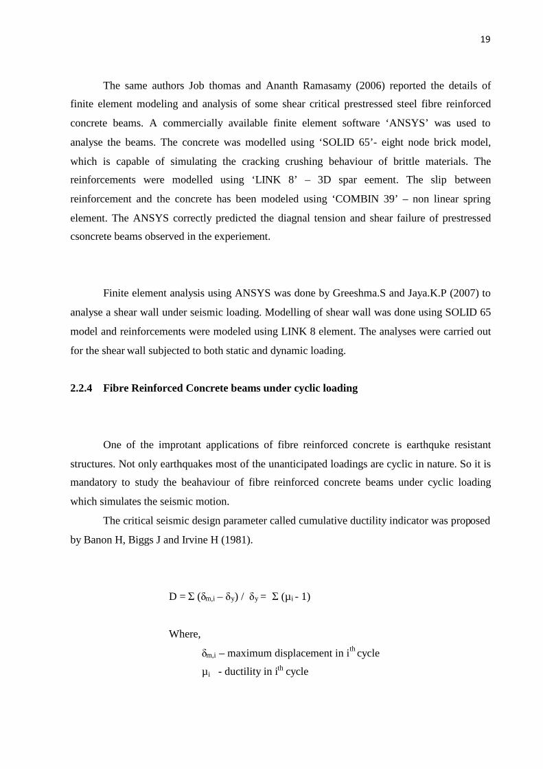
Fig.1 Concept of Ductility Enhancement
Figure 1 indicates the enhancement of ductility in the case of Fibre Reinforced Concrete
Composites. Hence the FRC has the potential application in Earthquake resistant structures.
Concrete composite
Normal concrete -actual
Codal curve for concrete
Strain
Stress
in
N/mm2
0.002 0.0035 0.0054

6
1.2.3 Limitations of Fibre Reinforced Concrete
Fibres, which are randomly distributed throughout the concrete, can overcome
cracks and control shrinkage more effectively. These materials have outstanding combinations
of strength and energy absorption capacity. In general, the fibre reinforcement is not a
substitution to conventional steel reinforcement. The fibres and steel reinforcement have their
own role in concrete technology. Therefore, many applications in which both fibres and
continuous reinforcing steel bars can be used together. However, fibres are not efficient in
withstanding the tensile stresses compared to conventional steel reinforcements. But, fibres are
more closely spaced than steel reinforcements, which are better in controlling crack and
shrinkage. Consequently, conventional steel reinforcements are used to increase the load
bearing capacity of concrete member; fibres are more effective in crack control. The lack of
corrosion resistance of normal steel fibres could be a disadvantage in exposed concrete
situations. The synthetic fibres are uneconomical to medium level people. Fire resistance of
synthetic fibres is also needed to be evaluated.
For example, 1 m3 of concrete will cost about Rs. 5,000/-. If 1% of steel fibre is put
to 1m3 of concrete, the cost of steel fibres would come around Rs.5,000/-. Hence people living
in rural areas that always prefer the non-engineered constructions can not use these fibres. So
for medium level constructions, particularly located in medium to high seismic prone areas
locally available new contruction materials which would cost are required to be cost effective.
1.3 WASTE FIBROUS RURAL MATERIALS
1.3.1 General
Concrete made with Ordinary Portland Cement has certain characteristics: it is
strong in compression and tends to brittle. The weakness in tension can be overcome by the use
of primary reinforcement rods and to some extend by the inclusion of a sufficient volume of
certain fibres. Moreover the use of fibres alters the behaviour of fibre-matrix composite after
concrete has cracked, there by improving its Ductility Since the conventional fibres like steel,
polypropylene and glass fibres have some limitations, focus on some other alternative materials
which are easy to find in the locality is important.

7
1.3.2 Local Materials
In India a great amount of Municipal Solid wastes and Agricultural wastes is
produced everyday. Reuse of such waste materials in concrete construction is happening
nowdays. But they are in the form of Aggregates, Cement (for example fly ash, brick wastes,
crusher powder etc,). Similarly only small quantity of work is concentrated on Composites,
particularly on natural waste materials. In many smaller towns and villages in the southern
parts of India, materials such as Rice Husk, Coir, Nylon Fibre and Sugarcane stems result in the
form of fibres and granular materials as waste. Such materials were chosen and properly treated
and shaped in the form of fibres or granules and introduced in concrete beams in critical zones
for accessing the properties by testing under middle third loading.
1.4 OBJECTIVES AND SCOPE OF THE STUDY
In the recent times, seismic effects have become a major governing factor in
analysis, design and construction in India. This is mainly due to the occurrence of medium to
severe earthquakes in regions which were not prone to earthquake earlier. Bhuj in the western
India and many cities in South India had experienced earthquakes after 1990 and earlier these
parts were considered as non-seismic zone. Due to this unexpected attack, losses in lives,
property and infrastructural resources are on the rise particularly in residential areas with
majority of non-engineered systems.
So, besides improving codal provisions and construction practices, it is necessary to
adapt local materials in construction with down-to-earth technology. So far the work on
composites is confined to application of aircraft & automobile industries with very little work
being imparted in civil infra-structural activities. The application of composites in civil infra-
structural activities mostly concentrated on the mechanical strength on composites and not on
its usage in structural system. On the other hand solid waste disposal has become one of the
major problems in modern cities. At present there are two major methods in practice to dispose
wastes. One is land filling and theother is burning. First one requires more valuable land and
second one pollutes the environment. So, alternate methods to dispose solid waste should be
found. By considering these requirements, here an attempt is made to study the possibilities of

8
reusing the coir fibre materials as fibre composites in concrete which not only tries to solve the
ductility problem but also the problem of waste disposal atleast to a small extent.
Hence the focus of the study is to characterize the mechanical, structureal and
microstructural properties of local and waste materials as composites in terms of flexibility,
ductility & energy absorption to improve seismic resistance. Since the materials chosen in this
research work are locally available materials, a detailed characterisation through various testing
and analytical mehtods are essential. Linear regresion analyses have been carried out for
mechanical strength properties and equations are proposed. The results of flexural testing have
been validated by doing the finite element analyses with commercially available software
‘ANSYS’.
The current approah to the design of earthquake resistant structures is based on damage
prevention during low magnitude earthquakes allowing some damage during moderate and
intermediate tremors and on prevention of collapse during severe earthqukes.A numerical
damage index has to be defined to facilitate the quantification of damage in analysis and design
of engineering systems. Damage indices are potentially valuable design tools, since they
provide a means by which different design or retrofi options can be compared objectively. So
here damge index based on ductiltiy and energy absorption are also eveluated according to the
previous proposed equations.

9
CHAPTER 2
LITERATURE REVIEW
2.1 GENERAL
In this chapter, an eloborative discussion is made regarding works done so far in
this area as literature review. Fibre reinforced concrete with different fibres and their behaviour
studies are discussed at the initial subheadings. Works on waste materials are discussed in the
subsequent headings comprehensively.
2.2 REVIEW ON FIBRE REINFORCED CONCRETE
2.2.1 General
Ronald F. Zollo (1997) presented an overview regarding history and development of
Fibre Reinforced Concrete in last 30 years. According to the literature, in the early 1960s, the
works on fibre reinforced concrete have been started. A lot of research works has been
conducted by many researchers on different fashions. Since local material is the focus of the
project, there is no much literature available in both national and international level. Even
majority of these projects have studied about steel fibres alone. So far there were only a few
works which have studied about the other fibres like nylon, plastic, rubber and natural fibres.
But those researches are completely different from the current study, since they have
concentrated along the material strength properties not on strucutral behaviour.
2.2.2 History and Development
The concept of using fibres in a brittle matrix was first recorded with the ancient
Egyptians who used the hair of animals and straw as reinforcement for mud bricks and walls in
housing.This dates back to 1500 B.C. (Balaguru et. al, 1992). During the same period, straws
were used to reinforce sun-baked bricks for a 57m high hill of ‘Aqar Quf’, near Baghdad.

10
During 1900’s that asbestos fibres were developed, manufactured and widely used to augment
mechanical properties of cement matrix as described by Bentur and Mindess (1990).
According to terminology adopted by American Concrete Institute (ACI) Committee
544, there are four catagories of Fibre Reinforced Concrete namely 1) SFRC (Steel Fibre
Reinforced Concrete), 2) GFRC (Glass Fibre Reinforced concrete), 3) SNFRC (Synthetic Fibre
Reinforced Concrete) and 4) NFRC (Natural Fibre Reinforced Concrete). It also provides the
information about various mechanical properties and design applications. Cement and Concrete
Institute also published the clasification of FRC in their website. Based on their classification,
Fibres are classified into Glass, Steel, Sythetic (includes Acrylic, Aramid, Carbon, Nylon,
Polyster, Polyethylene, Polypropylene) and Natural Fibres.
2.2.3 Mechanical Properties
C.B.Kukreja, S.K.Kaushik, M.B.Kanchi and O.P.Jain (1980) conducted some
experiments and reported that based on the results of three methods such as split tensile test,
direct tensile test and flexural test, split tensile strength test was recommended for fibrous
concrete. Here also increase in tensile strength and post cracking strength , toughnes were
reported.
Tensile strength of SFRC was also studied by researchers namely S.Goash,
C.Bhattacharya and S.P.Roy (1989) and reported as inclusion of suitable short steel fibres
increases the tensile strength of concrete even in low volume fractions. Optimum aspect ratio
was found as 80 and the maximum increase in tensile strength was obtained as 33.14% at a
fibre content of 0.7% by volume. Also it was reported that cylinder split tensile strength gave
more uniform and consistent results than the modulus of rupture test and direct tension test.
Stress – Strain characteristics of steel fibre reinforced concrete under compression was
studied by P.Sabapathi and H.Achyutha (1989). Cube compressive strength and Initial Tangent
Modulus of Elasticity were obtained and equation for stress-strain relation was also proposed.
Distribution and orientation of fibres in FRC significantly affects the properties of FRC.
Based on this concept Paviz Soroushian and Cha-Don Lee (1990) have carried out some

11
investigation by counting the number of fibres per unit cross sectional area of SFRC specimen
incorporationg various volume fractions of different fibres. Theoretical expressions were
derived for the number of fibres per cross sectional area in fibre reinforced concrete as a
function of volume fraction and length, assuming the cross sectional boundaries are the only
factors distributing the 3-D random oriention of fibres. Comparisions were also made between
number of fibres per cross sectional area and the reorientation fibres in concrete due to
vibration.
To ascertain the tensile strength of fibre reinforced concrete, a simple testing set up was
introduced to replace the costly direct tensile strength test apparatus by Youjiang Wang, Victor
C. Li and Stanley Backer (1990). Methodology and testing procedure were also given. But still
it requires servo controlled testing machine.
Stress – Strain behaviour of short, confined, reinforced concrete column with and
without steel fibres was ascertained by N.Ganesan and V.Ramana Murthy (1990). The volume
fraction of 1.5% with aspect ratio of 70 of steel fibres was used. The variable of the study was
percentage reinforcement of lateral reinforcement. The strain at peak loads was increased to
certain extent.
M. Ziad Bayasi and Paviz Soroushian (1992) reported that the rhelogical properties of
SFRC are significant. The large surface area and interlocking property of fibres leads formation
of balls among the concrete during mixing which can create damage to the hardened material
properties. An experimental investigation was conducted by them to study the fresh concrete
properties of concrete with different types of steel fibres. It was concluded that the fresh
concrete workability preoperties of FRC were significantly affected by fibre reinforcing index.
At a specific fibre reinforcing index, crimpled fibres seem to give slightly higher value than
plain fibres.
Balaguru and Shah (1992) have reported that the fibres that are long and at higher
volume fractions were found to ball up during the mixing process. The process called ‘balling’

12
occurs and causes the concrete to become stiff and a reduction in workability with increase
volume dosage of fibres. This has a tendency to influence the quality of concrete and strength.
Mechanical properties of high strength fibre reinforced concrete were also studied by
Faisal F Wafa and Samir A. Ashour (1992). A total of 504 test specimens were tested for
different mechanical properties such as compressive strength, split tensile strength, flexural
toughness and modulus of rupture. The mix was designed to achieve compressive strength of
94 N/mm2. Three volume fractions of steel fibres such as 0.5%, 1.0% and 1.5% were selected.
It was concluded that no real workability problem was encountered upto the addition of 1.5%
volume fraction of fibres in concrete. Steel fibres enhanced the ductility and post cracking load
carrying capacity of high strength concrete. 4.6%, 67%, 159.8% increase in compressive
strength, modulus of rupture and split tensile strength were achieved by introducing hooked
steel fibres as reinforcement in high strength concrete. Here also some emprical formulae were
proposed in terms of volume fraction of fibres and compressive strength of conventional
concrete.
fcf = fc + 3.53 Vf (2.7)
fr = 0.99 fc0.5 (2.8)
fsp = 0.58 fc0.5 (2.9)
where,
Vf = Volume fraction of fibres
Consolidation of concrete on split tensile strength was studied by A.M.Shaaban and
H.Gesund (1993). 0 to 8% of different mixes were selcted for the study. It is concluded that
split tensile strength is increasd by 20% due to external vibration than standard rodded
compaction.
Similar to the studies on steel fibre reinforced concrete, some works have also carried
out by the researchers on synthetic fibre reinforced concrete. Ziad Bayasi and Jack Zeng (1993)
have conducted some experimental works on workability and mechanical strength properties.
Fibrillated polypropylene fibres of length ½ inch and ¼ inch at three volume fractions 0.1, 0.3
and 0.5% were used in concrete and workability properties such as slump, inverted slum cone,
air content and mechanical strength properties such as compressive, impact and flexural
behaviour were studied. In addition to them rapid chloride permeability is also conducted.
13
Impact test was conducted according to ACI Committee 544 method. Number of blows
required to fail the cylindrical specimen is placed below a height of 457 mm. The hammer
weight was about 45.5 kg. From this extensive research work, it was concluded that
polypropylene fibres have no detectable effect on workablity upto 0.3%. Permeabilty of
concrete was increased due to the addition of polypropylene fibres. Similarly post – peak
flexural strength and impact resistance also increased due to the fibre addition.
Statistical prediction of compressive strength of steel fibre reinforced concrete has been
carried out by V.Kumar, S.D.Suman and Mohammad Shamim (1997) and reported that the
compressive strength of SFRC increases steeply with the increase of fibre content upto 1% (by
volume) beyond which the rate of increase in strength reduces. It was also reported that the
compressive strength of SFRC increases with the increase in the aspect ratio upto 60 and
beyond this the rate of increase in strength reduces. It was furhter concluded that Fibre
Reinforcing Index (FRI) significantly influences the compressive strength. the strength
increased upto FRI = 90 for stright fibres and FRI = 60 for crimpled fibres. Beyond these
values the rate of increase in strength started to decrease. They also proposed some statistical
emprical relationships between compressive strength and FRI.
fcf = afc + bx2 + cx2 + dx3 (2.4)
where,
x = Fibre Reinforcing Index (RI)
The values of co-efficients were determined using non-linear regression analysis as for
straight fibres, a = 1.003, b = 0.214653MPa, c = -0.001136MPa, d = -1.22657 x 10⁻⁶ Mpa
for crimped fibres, a = 0.904, b = 0.1075MPa, c = 0.0006928MPa, d = -8.841 x 10⁻⁶
Mpa
M.C.Nataraja et.al (1998) have conducted for a study on steel fibre reinforced concrete
under compression. Here the behaviour of steel fibre reinforced concrete under compression for
cylinder compressive strength ranged from 30 to 50 N/mm2. Round crimpled fibres with three
volume fracions of 0.5 percent, 0.75 percent and 1.0 percent and for two aspect ratios of 55 and
82 are considered. The effect of fibre addition to concrete on compressive strength was studied.
It was concluded that the addition of fibres increases the compressive strength and toughness.
Some square fitting line analyses were also done and some equations were proposed for
compressive strength in terms of fibre reinforcing index (length of fibre x volume fraction).
14
fcf = fc + 2.1756 (RI) (2.1)
(for strength upto 30 N/mm2)
fcf = fc + 2.145 (RI) (2.2)
(for strength between 30 to 50 N/mm2)
fcf = fc + 2.2604 (RI) (2.1)
(for strength upto 50 N/mm2)
An intresting study was carried out by Rami H. Haddad and Ahmed M. Asteyate (2001)
to predict the role of synthetic fibres such as polypropylene and nylon fibres in delaying steel
corrosion cracks and improving the bond with concrete. Different length of polypropylene and
nylon fibres with various volumes were mixed with concrete.Pullout tests and corrosion study
were conducted and concluded that both the fibres contributed more in delaying the corrosion
and improving the bond strength. Moreover it is pointed out that polypropylene firbes play a
major role than nylon fibre in the improvement of bond.
Another intresting investigation was carried out by Yaghoub Mohammadi ans
S.K.Kaushik (2003) about the effect of mixed aspect ratio of fibres on mechanical strength
properties of concrete. 25 mm – 50 mm long crimped type flat steel fibres were mixed in
different proportions with concrete and tested for split tensile, compressive, static flexural
strength. Compressive toughness and flexural toughness were obtained from the test results. It
is found that use of 65% long fibres and 35% short fibres gives optimum composite properties
when compared with other mixes. An important note also was given in that literature that use of
mixed aspect ratio of fibres does not have a significant effect on the static modulus of elasticity.
Wu Yao, Jie Li and Keru Wu (2003) have examined the mechanical behaviour of hybrid
fibre reinforced concrete at low fibre volume fraction. Three hybrid composites such as
polypropylene and carbon, carbon and steel and steel and polypropylene fibres were chosen and
the mechanical strength properties such as Compressive strength, split tensile strength, modulus
of rupture and flexural toughness were ascertained. A statistical response surface method and
three level full factorial experimental design were used to study the effects of volume fraction
and aspect ratio of fibre on fractional energy, compressive strengh, splitting tensile strength,
flexural strength and characteristic length of steel fibre reinforced concrete. When the
mechanical properties are alone considered, the optimal values of design variables such as

15
0.64% for volume fraction and 76.44 for aspect ratio were obtained. If both mechanical
properties and cost optimisation are considered, volume fraction of 0.558% and aspect ratio of
75.87 were obtained.
Job thomas and Ananth Ramasamy (2007) carried some experimental investigation on
mechanical properties of steel fibre reinforced concrete. Three different strengths such as
normal strength (35 MPa), moderately high strength (65 Mpa) and high strength (85 Mpa)
concrete mixes were selected for this study. 30 mm long steel fibres ( Aspect ratio of 55) with
three different volume fractions as 0.5%, 1.0% and 1.5% were selected and uniformly
distributed in the mix. The mechanical strength properties such as compressive strength, split
tensile strength, modulus of rupture and post cracking performance, modulus of elasticity,
poisson’s ratio and strain corresponding to peak compressive stress were studied. Based on 60
test data regression analysis is done and emprical relations were provided.
Based on the test results of 320 numbers of specimens on mechanical strength
properties of high strength fibrous concrete, J.Premalatha and R.Sundararajan (2007) suggested
no significant improvement in compressive strength was obtained beyond 1.5% volume
fraction of steel fibre content. The high strength concrete mix was designed to achieve 60
N/mm2 and their strength properties like compresive strength, modulus of rupture, split tensile
strength were studied and emprical relations were also proposed in terms of Fibre Reinforcing
Index (FRI).
frf = fr +5.85F (2.5)
fspf = fsp +3.42F (2.6)
where,
F = Fibre Reinforcing Index (RI)
Effects of aspect ratio and volume fractions of steel fibre on the mechanical properties
of SFRC were studied by Semsi Yazici et.al (2007). Three aspect ratios (l/d) of 45, 65, 80 and
three volume fractions of 0.5%, 1.0%, 1.5% hooked end bundled fibres were taken in that
study. Increase in the aspect ratio decreases the workability. In compressive strength 4 – 19%
16
incraese, in split tensile strength 11 – 54% increase and in flexural strength 3 – 18% increase
were obtained from the experimental investigation. A multilinear regression analysis was used
to obtain the following relationships.
fc (Mpa) = 50.4869 + 0.0434 x l/d + 1.9667 x Vf (%) (2.10)
fsp (Mpa) = 2.2121 + 0.0077 x l/d + 1.4233 x Vf (%) (2.11)
fr (Mpa) = 0.8261 + 0.0638 x l/d + 3.000 x Vf (%) (2.12)
2.2.4 Fibre Reinforced Concrete beams under static loading
M.Lakshmipathy and A.R.Santhakumar (1987) have conducted an experimental
analytical investigation on two span continuous beams with steel fibres. The important
characteristics such as cracking behaviour, ductiltiy and energy absorption were ascertained
from experimental investigation and compared with analytical results. The fibrous concrete
beams served superior than conventioanl concrete.
An experimental investigation was carried out by D.L.N Rao, M.R.A Kadir and Kawa
Taha Abu Al Awffa (1987) on deformation characteristics and strength of reinforced concrete
beams made with steel fibres in pure bending. 1.85m span beams were casted and tested under
static flexural loading. The increase in depth of neutral axis and hence flexural stiffness of fibre
reinforced concrete beams at all stages of loading reflected the ability of fibres in arresting the
crack growth. The inclusion of steel fibres in the concrete significantly increased the post
cracking stiffness at all the stages upto failure. Lim.T.Y, Paramasivam.P and Lee.S.L (1998)
carried out some experimental and analytical study on bending behaviour of steel fibre
reinforced concrete beams. A simplified Moment – Curvature (M–Ø) relationship for beam
with rectangular was proposed. The proposed model was verified with experimental results
carried out 2.2m span reinforced concrete beams. The enhancement in ductility and energy
absorption under static loading was delivered through the study.
Balaguru and Shah (1992) reported that the modern developments of using only straight
steel fibres began in the early 1960’s. Till now, a wide range of other type of fibres was used in
17
cement matrices. Construction industries have led the development of conventional fibres such
as steel, stainless steel and glass.
Cheng-Tzu Thomas Hsu, Rujun Linda He and Samer Ezeldin (1992) were presented a
computer algorithm to analyse the load – deflection and moment – curvature behaviour of steel
fibre reinforced concrete beams. A total of 11 SFRC simple beams were casted and tested
under two point loading. The experimental results obtained were compared with computer
program results.
Flexural behaviour of fibre reinforced concrete beams were experimented by
H.V.Dwarakanath and T.S.Nagaraj (1998). In this study fibres were put in two types of
locations such as over the entire depth and oner half the depth of the beam on the tension side.
20 numbers of 1.8m long reinforced concrete beams with steel fibres were tested under flexural
static loading. Midspan deflections and curvatures at salient points such as cracking, and
ultimate points were compared. It is found that half depth mode of inclusion of fibres for under
reinforced concrete beams and full depth mode of inclusion of fibres for over reinforced
concrete beams.
Antonia F. Barbosa and Gabriel O. Ribeiro (1998) worked on ANSYS for finite element
analysis of reinfroced concrete structures. A simply supported reinfroced concrete beam
subjected to uniformly distributed load was taken as a simple example in that study. Two
different models were considered for steel reinforcement such as discrete and smeared. Load –
deflection curves obtaind through ANSYS have been compared with experimental results and
found satisfactory.
Piti Sukontasukkul (2004) conducted an experiemntal investigation on toughness of
steel and polypropylene fibre reinforced concrete beams under bending using two different
methods such as ASTM C1018 and JSCE SF-4. The behaviour of steel fibre reinforced
concrete was single peak response whereas polypropylene fibre reinforced concrete was double
peak response. The deformations under two methods were compared.

18
Earlier a similar study has been conducted by S.K.Padmarajaiah and Ananth
Ramaswamy (2004) on flexural strength of steel fibre reinforced high strength concrete in fully
and partially prestressed beam specimens. It is found that the toughness and ductility of
prestressed high strength concrete beams have been increased with the increase in fibre content.
The maximum increase in ductility was 18%, 45% and 68% and percentage increase in energy
absorption 25%, 78% and 88% for fully prestressed beams with full depth of steel fibre content
of 0.5%, 1.0% and 1.5% volume fractions.
Experimental investigation and Analytical modeling for flexural behaviour of
reinforced fibrous concrete beams using synthetic fibres were performed by D.Suji,
S.C.Natesan and R.Murugesan (2006). Graded fibrillated polypropylene fibres were used in
this study. 1.8 m long rectangular reinforced concrete beams were casted with and without fibre
at different volume fractions of 0.1%, 0.2% and 0.3%. Moment carrying capacity of beams
were arrived and compared with theoretical equations. Also it was concluded that the crack
pattern was remains same for all beams, but the rack with and length were reduced for fibre
reinforced concrete beams.
Ultimate strength of steel fibre reinforced self compacting concrete beams were tested
by Ganesan.N, Indira.P.V and Santhosh kumar.P.T (2006). 1.2m long reinforced concrete
beams are prepared using self compacting concrete with steel fibres of three volume fractions
of 0.25%, 0.5% and 0.75%. It is foiund that strength and ductility of fibre reinforced self
compacting concrete specimens have increased substantially over conventional concrete.
Load – Deflection performance of partialy prestressed concrete T-beams with steel
fibres in partial and full depth was assessed by J.Thomas and A.Ramasamy (2006). Three
mixes M35, M65 and M85 were used with steel fibres at a volume fraction of 1.5%. Totally 6
numbers of 3.85 m long T-beams with simply supported span of 3.6m prestressed with 7 mm
wires were casted and tested under four point bending. Analytical models were proposed for
computation of load – deflection and moment – curvature. Comparisions were made between
the experimental and analytical results.
19
The same authors Job thomas and Ananth Ramasamy (2006) reported the details of
finite element modeling and analysis of some shear critical prestressed steel fibre reinforced
concrete beams. A commercially available finite element software ‘ANSYS’ was used to
analyse the beams. The concrete was modelled using ‘SOLID 65’- eight node brick model,
which is capable of simulating the cracking crushing behaviour of brittle materials. The
reinforcements were modelled using ‘LINK 8’ – 3D spar eement. The slip between
reinforcement and the concrete has been modeled using ‘COMBIN 39’ – non linear spring
element. The ANSYS correctly predicted the diagnal tension and shear failure of prestressed
csoncrete beams observed in the experiement.
Finite element analysis using ANSYS was done by Greeshma.S and Jaya.K.P (2007) to
analyse a shear wall under seismic loading. Modelling of shear wall was done using SOLID 65
model and reinforcements were modeled using LINK 8 element. The analyses were carried out
for the shear wall subjected to both static and dynamic loading.
2.2.4 Fibre Reinforced Concrete beams under cyclic loading
One of the improtant applications of fibre reinforced concrete is earthquke resistant
structures. Not only earthquakes most of the unanticipated loadings are cyclic in nature. So it is
mandatory to study the beahaviour of fibre reinforced concrete beams under cyclic loading
which simulates the seismic motion.
The critical seismic design parameter called cumulative ductility indicator was proposed
by Banon H, Biggs J and Irvine H (1981).
D = Σ(δm,i – δy) / δy = Σ(µi - 1)
Where,
δm,i – maximum displacement in ith cycle
µi - ductility in ith cycle

20
Roufail and Meyer (1987) proposed some analytial modelling of hysteretic behaviour of
reinforced concrete strucutres. Measures of stiffness degradation have been considered as
damage indicators.
Kf (km – k0)
D = ------------------
Km (kf – k0)
Where,
kf – Secant stiffness at failure
km– Secant stiffness at the maximum deformation caused
by the applied loads
ko – Initial tangent stiffness
But in the above equation effect of repeted cycclic loading was not considered.
Kratzig W.B, Meyer I.F and Meskouris K (1989) propsed a model to evaluate the
damage index in reinfroced concrete under cyclic loading. The proposed damage index was
based on the hysteric energy absorbed by a member. The first loading cycle at given amplitude
is termed as primary half cycle, with subsequent cycle at the same or smaller amplitudes termed
as follows. Then the damage index for the positive half cycle was defined as
ΣE+p,i + ΣE+
i
D+ = ------------------
ΣE+f + ΣE+
i
Where,
E+p,i – energy absorped in a primary half cycle
E+I - energy absorped of a follower half cycle
E+f – energy absorped in monotonic test to failure
With a similar index defined for a negative cycles, overall damage index was given by,
D = (D+ + D-) – (D+D-)

21
Wang M.L and Shah S.P have proposed a reinfroced concrete hysteritic model on the
damage concept. The proposed damage was a simple one in which the rate of accumulation of
damage is assumed proportional to the damage already incurred. The proposed equation was
exp(sα) - 1
D = ---------------
exp(s) - 1
Where,
δm,i
α= cΣ-----
δf
c, s are constants, the value of constants c = 0.1 and s = 1.0 for well reinforced
member.
Simulation of highly ductile fibre reinforced cement based composite componenets
under cyclic loading was carried out by Tong-Seok Han, Peter h. feenstra and Sarah L.
Billington (2003). Experiments on cantilever beams and corresponding finite element models
were proposed in the literature.
Similarly cyclic response of highly ductile fibre reinforced cement based composites
were ascertained by Keith E. Kesner, Sarah L.Billington and Kyle S. Douglas (2003) and
reported that improvement in performance was in DFRCC members.
U.B. Choubey, Uttamasha and B.K.Prasad (2006) have reported some studies on cyclic
behaviour of latex modeified reinforced concrete beams. Tests on 14 numbers of different
reinforced concrete beams with and without latex were casted and studied. In that study
forward cyclic loading was applied and load-deflection curves were obtained.

22
2.2.5 Fibre Reinforced Beam Column Joint under cyclic loading
An experimental investigation was conducted on the behaviour of beam-column joints
with inclined reinforcing bars under seismic condition and reported by A. G. Tsonos, I. A.
Tegos and G. Gr. Penelis (1992). By conducting experiments on twenty joints, it was concluded
that, improvement in the ductile behaviour of exterior beam-column joints resulting in the
presence of inclined reinforcing bars in their core region.
A MS thesis was presented by Michael Gebman (2001) on the application of SFRC in
building frames to help provide a basis for possible modifications to the building code. The
thesis was focused on frame joints, particularly on the improvement in joint seismic
performance by using steel fibre reinforced concrete. By adding hooked steel fibres to
reinforced concrete, the joint was toughened which enables the structure to survive strong
earthqukes. Simulated quasi-static earthquke loading was applied on the joints and hysteresis
loops were drawn. Based on the curves, ductility, beam cracking and column cracking were
observed carefuly and found that stel fibres enhances all the structural behavior of joints.
SIFCON is a special type of fibre reinforced concrete at high volume fraction (4 to
20%) in which the formwork is filled to capacity with steel fibres and the resulting fibre
network is then infiltrated by a cement based slurry. Ductile behaviour of SIFCON structural
members were studied by G.S.Thirugnanam, P.Govindan and A.Sethurathnam (2001). The
investigation was carried out in two stages. Initially single span beams were tested to quantify
the structural behaviour in the hinging zones of flexural members. In the second stage, multi
bay,multi-storey RC frames were tested with SIFCON beam-column joints to study the
structural behaviour under cyclic loading. The seismic parameters such as cumulative ductiltiy,
cumulative energy absorption, stiffness degradation and failure mode were obtained. It was
concluded that Ductiltiy was increased to 100% and energy absorption was increased about
50% in hinging zones of structural joints because of SIFCON.

23
An experimental investigation was carried out by Mustafa GENCOGLU, Iihan EREN
(2002) to study the effect of steel fibre reinforced concrete on the behaviour of the exterior
beam-column joints subjected to reverse cyclic loading. To achieve the ductility in joints for
earthquake resistant structures, closely spaced reinforcements are recommended by the code.
To avoid the congestion of reinforcement, alternate solution was given in the literature. Steel
fibres of aspect ratio 75 were added at a 1% volume fraction. Tests were conducted by applying
reverse cyclic loading and mode of failure and energy dissipation capacity was observed. It was
concluded that steel fibres can be used as alternative for the increase in confining reinforcement
so as to minimise the congestion of reinforcement at beam-column joint and hence reduce the
problem of consolidation of concrete.
Intrinsic response control of moment resisting frames using advance composite
materials and structural elements was tested by Gregor Fischer and Victor C. Li (2003). In this
research work, the load-deformation response of a composite frame system under reverse cyclic
loading condition was investigated. From this work it was concluded that engineered
cementatious composites and fibre reinforced polymer reinforcements can be used as
alternative approach for earthquke resistant structures with improved performance in terms of
dynamic response, residual displacement, damage tolerance and rehabilitation requirements.
Seismic performance of confined high strength concrete square columns with carbon
fibre reinforced polymers were experimented by A.Hosseini, Ali R. Khaloo and S.Fadaee
(2005). To evaluate the performance of high strength, reinforced concrete columns confined
with carbon fibre reinforced polymers, six square concrete columns were tested under constant
axial load and cyclic lateral load. The energy damage indicator and ductiltiy parameters of
strengthened columns were improved. Both system and section ductility and energy dessipation
were improved considerably in strengthened joints.
As seismic design of structures moves towards performance based design, there is need
for a few strcutural members and systems that possess enhanced deformation capacity and
damage tolerance, while requiring simple reinforcements.One option for achieveing thiss goal
was given and experimented by Gustavo J. Parra-Montesinos, Sean W. Peterfreund and Shih-
HO Chao (2005). Using High-performeance fibre-reinforced cement composites, high damage
tolerant beam-column joints were achieved. It is concluded that beam-column joints
24
constructed with an HPFRCC material containing a 1.5% volume fraction of ultra-high
molecular weight polyethylene fibres exhibited excellent strength, deformation capacity and
damage tolerance. It is also reported that use of HPFRCC materials in beam plastic regions
allowed an increase in transverse reinforcement spacing to half the effective beam depth.
P.Asha et.al (2006) carried out an experimental investigation on cyclic response of
reinforced concrete exterior beam – column joints. Two types of reinforcement were considered
namely circular hoop and conventional reinforcement. Load-displacement hysteresis loops
were drawn and hence cumulative enerfgy absorption and ductility were ascertained. Similar
study was carried out by Valeria Corinadesi and Giacomo Moriconi (2006) on behaviour of
beam-column joints made of sustainable concrete. In this two different types of aggregares
namely natural aggregates and recycled aggregates were used. In order to ascertain the real
scale behaviour, several beam-column joints were casted and tested under low cycle loading.
There are two options in seismic design. One is design of structures with full strength so it will
respond elastically while ensuring adequate ductility and energy absorption. Second one
permits the structure to be designed for considerably lower forces than those required for first
one. Here also ductility and energy dessipation capability were ascertained based on the load-
displacement hysteristic loops.
Strength and ductility of partially confined bridge column under seismic loading were
studied by D.Prapakaran and R.Sundararajan (2007). The main objective of the study was to
investigate the influence of partial confinement at plastic hinge region on the structural
characteristics of circular bridge column. Based on the lateral load - tip displacement hysteristic
loops, cumulative energy absorption were calculated and compared.
2.2 REVIEWS ON WASTE FIBROUS MATERIALS
2.2.1 General
India owns huge amount of waste materials in the form of organic and inorganic state.
Nowadays inorganic waste materials such as plastic, nylon, rubber are produced in massive
volumes because of increase in use of inorganic materials for various purposes such as
automobile parts, households, industrial wastes etc., One of the leading problem of generating

25
these inorganic waste materials is disposal without environmental pollution. Common methods
of solid waste disposal are land filling and incineration. But these methods lead uneconomic.
So, attempts to reuse the waste materials for construction purposes have been made by many
researchers in many forms. Similarly organic natural fibres are abundantly available in many
parts of the world. For different reasons, developing countries recognise the importance of the
use of ecologically friendly and cost effective materials in urban and rural buildings. This
section will elaborate the studies carried by the researchers on inorganic fibrous materials.
2.2.2 Review on inorganic fibres
Gonzalo Martinez-Barrera et.al (2006) reported about concrete reinforced with
irradiated nylon fibres. Modified nylon fibres were mixed with cement mortar at 1.5%, 2.0%
and 2.5% volume fractions. The compressive strength of the fibre reinforced concrete was
evaluated.
Some studies on properties of concretes containing reengineered plastic shred fibre were
studied by K.Anbuvelan, M.M.Khadar, M.H.Lakshmipathy and K.S.Sathyanarayanan (2007).
Reengineered plastic shred fibres are made by re-processing the plastic waste and then rolling it
into plastic sheets which were subsequently shredded into fibres of required dimensions.
Compressive, split tensile, flexural, abrasion, impact strength and plastic shrinkage studies
were studied by the authors. It was concluded that the engineering properties were improved by
the addition of plastic shred fibres.
2.2.3 Review on Natural Fibres
Natural fibres are prospective reinforcing materials and their use until now has been
more traditional than technical. They have long served many useful purposes but the
application of materials technology for the utilization of natural fibres as the reinforcement in
concrete has only taken place in comparatively in recent years. The distinctive properties of
natural fibre reinforced concretes are improved tensile and bending strength, greater ductiltiy,
greater resistance to cracking and hence improved impact strength and toughness. Besides its
ability to sustain loads, natural fibre reinforced concrete is also required to be durable.
Durability relates to its resistance to deterioration resulting from external causes as well as
internal causes (M.A.Aziz, P.Paramasivam and S.L.Lee 1984).
26
Mechanical characterization and impact behaviour of concrete reinforced with natural
fibres were studied by S.K. Al-Oraimi and A.C.Seibi (1995). Here an experimental study was
conducted using glass and palm tree fibres on high strength concrete. Mechanical strength
properties such as compressive, split tensile, flexural strengths and post cracking toughness
were studied. It was concluded that natural fibres are comparable with glass fibres. A finite
element analysis was also done using ANSYS software. Both analytical and
experimental results were compared and acceptable.
Rheological properties of coir fibre reinforced cement mortar were carried out by
G.Ramakrishna and T.Sundararajan (2002). Flow value, cohesion and angle of internal friction
were determined for three diffrenet mix ratios and four different aspect ratios and fibre
contents. Based on the rheological properties of fresh mortar, it was recommended to use
shorter fibres with low fibre-content for achieving workability and higher fibre content for
better cohesiveness in wet state.
G.Ramakrishna, T.Sundararajan and Usha Nandhini (2002) compared the theoretical
and experimental investigations on the compressive strength and elastic modulus of coir and
sisal fibre reinforced concretes for various volume fractions. It was observed that both the
experimental and analytical values of elastic modulus had shown 15% discrepancy, which can
be regarded as comparitively small.
Sugarcane bagasse fibre reinforced cement composites were studied by K.Bilba,
M.A.Arsene and A.Ouensanga (2003). Various bagasse fibre-cement composites were prepared
and influence various parameters on the setting of the composite materials were studied.
Botanical components, thermal and chemical treatment of bagasse fibres were also studied.
The natural fibre composites may undergo a reduction in strength and toughness as a
result of weakening of fibres by the combination of alkali attack and mineralisation through the
migration of hydrogen products to lumens and spaces. Romildo D. Toledo Filho, Khosrow
Ghavami, George L. England and Karen Scrivener (2003) reported their study on development
of vegetable fibre-mortar composites of improved durability. So, several approaches were
proposed by the authors to improve the durability of vegetable fibre-cement composites. These
include carbonation of the matrix in a CO2-rich environment; the immersion of fibres in

27
slurried silica fume prior to incorporation in Ordinary Portland Cement matrix; partial
replacement of Ordinary Portland Cement by undensified silicafume or blast furnace slag. The
performance of modified vegetable fibre-mortar composites was analysed in terms of effects of
aging in water, exposure to cycles of wetting and drying and open air weathering on the
microstructures and flexural behaviour. It was suggested that immersion of natural fibres in a
silica fume slurry before the addition to the cement based composites was found to be effective
means of reducing embrittlement of the composite in the environments. Also early cure
composites in a CO2-rich environment and the partial replacement of OPC by undensified
silicafume were the efficient approaches in obtaining natural fibres in improved durability.
Robert S.P. Coutts (2005) reviewed critically about the Australian research into natural
fibre cement composites. It was mentioned that over the last three decades considerable
research has been commited to find an alternative fibre to replace asbestos and glass fibres.
V.Agopyan et.al (2005) reported the devlopments on vegetable fibre-cement based materials in
Brazil. Taking into account the mechanical properties, with an adequate mix design, it is
possible to develop a material with suitable properties for building purposes. To overcome the
drawback, it was suggested that durability of natural fibres can be impoved by making
alternative binders with controlled free lime using ground granulated blast furnace slag.
Romildo D. Toledo Filho et.al (2005) made some experiments on free, restrained and
drying shrinkage of cement mortar composites reinforced with vegetable fibres. The free and
restrained shrinkage were studied by subjecting the specimens to wind speed of 0.4-0.5 m/s at
40o C temperature for upto 280min. Drying shrinkage tests were carried out at room
temperature with about 41% relative humudity for 320 days. It was concluded that free plastic
shrinkage is significantly reduced by the inclusion of 0.2% volume fraction of 25mm short sisal
fibres in cement mortar. Also it was stated that the presence of sisal and coconut fibres
promotes an effective self-healing of plastic cracking after 40 days at 100% RH. The drying
shrinkage was increased by upto 27% when up to 3% of sisal and coconut fibres were present
in that stud.

28
The capability to absorb energy, called toughness is important in actual service
conditions. For that an experiemntal investigation was carried out by Ramakrishna.G and
Sundararajan (2005) on impact strength of a few natural fibre reinforced cement mortar slabs.
Four types of natural fibres such as coir, sisal, jute and hibiscus cannebinus with four different
fibre contents such as 0.5%, 1.0%, 1.5% and 2.0% by weight of cement were used. The tests
were carried using repeated projectile test apparatus and the performance of specimens was
ascertained based on the parameters namely impact resistance, residual impact ratio, crack
resistance ratio and the condition of fibre at ultimate. From this elaborative test results, it was
concluded that coir fibres absorb more energy ie., 253.5 J at 2% fibre content and fibre length
of 40 mm. Coir fibre reinforced slab specimens exhibit fibre pull out failure, whereas all other
types of fibre reinforced specimens exhibit fibre fracture at ultimate failure.
Some studies have been also conducted by Ramakrishna.G and Sundararajan (2005) on
the durability of natural fibres and the effect of corroded fibres on the strength of mortar. Coir
fibres were found to retain higher percentages of their initial strength than all other fibres after
the specified exposure in the various mediums.
Mechanical properties of date palm fibres and concrete reinforced with date palm fibres
were tested and reported by A.Kriker et.al (2005) in two different climates. In addition to the
above properties, continuity index, microstructure and toughness were also studied. The
volume fraction and length of fibres chosen were 2-3% and 15-60mm respectively. It was
concluded that male date palm fibre got more tensile strength. Also it was stated that observing
micro-structue of the fibre-matrix interface cured in hot-dry and water environments. Based on
the results and observations of that work, it was suggested that future research should be
developed on the treatment of Male date palm surface fibre concretes to improve their
mechanical properties using local industrial wastes, especially hot-dry climate.
Microstructure and mechanical poperties of waste fibre-cement composites were studied
by H. Savastano Jr, P.G.Warden and R.S.P.Coutts (2005). Both secondary and back-scattered
electron imaging and energy dispersive X-ray spectrography were used for compositational
analysis. It was concluded that sisal waste fibres presented satisfactory bonding in matrices.
BSE images and EDS analyses confirmed the fibre-matrix transition zone can be improved by
using production process based on vaccum dewatering and pressure.

29
K.Murali Mohan Rao and K.Mohana Rao (2005) introduced and studied the extractio
and tensile properties of new natural fibres used as fillers in a polymeric matrix enabling
production of economical and light weight composites for load carrying structures. The cross
sectional shape, the density and tensile properties of these fibres along with established natural
fibres like sisal, bana, coconut and palm were determined experimentally under similar
conditions and compared. The density of newly introduced fibres such as vakka, date and
bamboo were less than the existing fibres.
30
CHAPTER 3
EXPERIMENTAL INVESTIGATION
3.1 INTRODUCTION
This chapter demonstrates the detailed exprimental programme of this investigation . It
includes materials and fibres used, detailed methodology of experimetal programme, mix
proportions, specimen details, reinforcement detailing and test set up. In this experimental
investigation, initially three organic fibres such as plastic, nylon, tyre and three inorganic fibres
such as coconut coir, sugarcane bagasse and rice husk have been taken. The properties are
compared with well known steel fibres. Their physical properties such as aspect ratio, specific
gravity, water absorption, density and ultimate tensile load are studied. However natural
inorganic fibres are subjected to ageing process in different environments in which they may
suffer a reduction in strength and toughness. So it is mandatory to study the microstructure
properties of fresh as well as used (reacted with concrete for two years) natural fibres through
SEM with EDS and X-ray difraction. Since the focus of this research is aimed on reuse of
waste fibrous materials, an overall characterization with different characteristics are required to
recommend the materials. This characterization is divided into many parts. Initially seven fibres
(steel, nylon, plastic, tyre, coconut coir, sugarcane bagasse and rice husk) of three different
aspect ratios (30, 60, 90) and three volume fractions (0.5%, 1.0% and 1.5%) have been taken.
First the influence of different fibres on workability of concrete are studied. Whilst the slump
test is commonly used to assess the workability of conventioanl concretes, it is not generally
suitable for natural fibre reinforced concrete (Aziz M.A et.al 1984). Hence in this investigation,
both slump test as well as Vee-bee test have been conducted to assess the workability of fibre
reinforced concretes.
To achieve the optimim length and volume fractions of fibres for structural studies,
mechanical strength properties such as compressive strength, split tensile strength, modulus of
rupture, modulus of elasticity, shear strength and impact energy have been conducted. From the
test results optimum length of 50mm and two different volume fractions 0.5% and 1.0% have

31
been selected for further structural study. Behaviour of reinforced concrete beams with all
seven fibres of two different volume fractions have been studied under both monotonic and
cyclic (psuedo static) loading. From the performance behaviour of beams nylon, plastic and
coir fibres of 1.0% volume fraction are slected for further study. Since the field studies have
shown that beam-column joints are vulnerable during an intensive earthquake, the work has
been extended to study the behaviour of beam-column joints with fibre composites.
Besides the strength behaviour, durability of proposed concrete is also important.
Durability relates to its resistance to deterioration resulting from external and internal causes.
The internal causes include volume change and permeability of concrete. So, in this study
effects of plastic shrinkage, drying shrinkage and permeability on selcted fibre reinforced
concrete have been studied.
3.2 MATERIALS AND MIX
The materials used in this investigation were: ordinary portland cement, coarse
aggregate of crushed rock with a maximum size of 20 mm, fine aggregate of clean river sand
and portable water. 8mm dia HYSD bars were used as main reinforcement. 6mm dia MS bars
were used as stirrups. Commercially used MS wires (binding wires) were used as steel fibres.
Locally available materials such as nylon, plastic, tyre, coconut coir, sugarcane bagasse, rice
husk were taken from the waste stream and converted in to fibres of required length and
diameter. The detailed properties are given in subsequent contents.
3.2.1 Cement
Ordinary Portland Cement of 43 grade conforming to IS 8112-1989 was used. Tests
were carried out on vatious physical properties of cement and the results are shown in Table 3.1
3.2.2 Fine Aggregate
Natural river sand was used as fine aggregate. The properties of sand were determined
by conducing tests as per IS: 2386 (Part- I). The results are shown in Table 3.2. The results
obtained from sieve analysis are furnished in Table 3.3. The results indicate that the sand
conforms to Zone II of IS: 383 – 1970

32
3.2.3 Coarse Aggregate
Crushed granite stones obtained from local quaries were used as coarse aggregate. The
maximum size of coarse aggregate used was 20 mm. The properties of coarse aggregate were
determined by conducting tests as per IS: 2386 (Part – III). The results are tabulated in Table
3.4
3.2.4 Water
Portable water free from salts was used for casting and curing of concrete as per IS: 456
– 2000 recommendations.
3.2.5 Fibres
Locally available waste materials were collected from different stream and properly
shaped in the form of fibres. Uniform length of fibres was obtained by using cutting machine.
Plastic fibres were colleceted from plastic pot industry waste. Nylon waste fibres were
collected from nylon industries.
Table.3.1 Physical Properties of 43 Grade Ordinary Portland Cement
Physical Properties Values of OPC usedRequirements as per IS
8112-1989
Standard Consistency 29.2% -
Initial Setting Time 45 Minutes Minimum of 30 minutes
Final Setting Time 265 Minutes Maximum of 600 minutes
Specific gravity 3.15 -
Compressive strength in
N/mm2 at 3 days29 Not less than
Compressive strength in
N/mm2 at 7 days38.5 Not less than
Compressive strength in
N/mm2 at 28 days48 Not less than

33
Bi-cycle rubber tyres were collected from local automobile workshops. Locally and
easily available natural fibres such as coconut coir fibre, sugarcane baggasse and rice husk were
collected from local coconut oil mills, sugar industries and rice mills respectively.
Commercially available GI Steel wires which are used as binding wires for reinforcement tieing
were used. The clear photographs of different fibres are shown in Fig. 3.2 to Fig.3.8. The
geometrical and physical properties of different fibres are tabulated in Table 3.5.
Table.3.2 Sieve Analysis of Fine Aggregate
I.S. Sieve Size Weight
Retained (gm)
Cumulative
Weight
Retained (gm)
Cumulative
Percentage
Weight
Retained
Cumulative
Percentage
Weight Passing
10 mm 2 2 0.4 99.6
4.75 mm 6 8 1.6 98.4
2.36 mm 20 28 5.6 94.4
1.18 mm 76 104 20.8 79.2
600 microns 224 328 65.6 34.4
300 microns 114 442 88.4 11.6
150 microns 54 496 99.2 0.8
< 150 microns 4 500 100 0.0
Remarks: Conforming to Zone II of Table 4 of IS: 383-1970
Table.3.3 Physical Properties of Fine Aggregate
(Tests as per IS: 2386 – 1968: Part III)
Physical properties Values
Specific gravity 2.6
Fineness Modulus 2.83
Water Absorption 0.75%
Bulk density (kg/m3) 1654
Free moisture content 0.1%

34
Table.3.4 Physical Properties of Coarse Aggregate
(Tests as per IS: 2386 – 1968 Part III)
Physical properties Values
Specific gravity 2.6
Fineness Modulus 2.73
Water Absorption 0.5%
Bulk density (kg/m3) 1590
Free moisture content (%) 0.2%
Aggregate Impact value (%) 11.2
Aggregate Crushing value (%) 25.12
Diameter of fibres were measured through microscope of capacity……. . The specific
gravity was determined based on the method specified in IS: 2386 (Part III). Five gram of each
fibre samples was accurately weighed in an electronic balance of accuracy….. and the water
absorbed after 24 hours of continuous immersion was determined. Except for rice husk, the
ultimate tensile strength was determined by the tension test using 4 kN tensile testing machine.
A gauge length of 100 mm was chosen to measure the maximum elongation.
Table.3.5 Typical Properties of Fibres
Type of FibreProperties of Fibres
Steel Nylon Plastic Tyre Coir Sugarcane Rice
Husk
Diameter/Equivalent
Diameter (mm)
0.60 0.44 1.51 1.50 0.48 1.50 1.60
Aspect Ratio 83.3 113.6 33.1 33.1 104.2 33.1 12.5
Specific gravity 5.86 0.7 1.25 1.08 0.87 0.52 0.4
Water Absorption (%) 33.33 66.66 66.66 75 210 286.6 225.66
Density in kg/m3 6879 657 763 530 2057 260 564

35
Fig.3.1 Steel Reinforcements Fig.3.2 Steel Fibres
Fig.3.3 Nylon Fibres Fig.3.4 Plastic Fibres
Fig.3.5 Tyre Fibres Fig.3.6 Coir Fibres
Fig.3.7 Sugarcane Fibres
Fig.3.8 Rice Husk Fibres
36
3.2.6 Reinforcements
Fe 415 steel bars of diametrs 8 mm and 12 mm were used as main reinforcements for
beams and beam-column joints respectively. Mild steel 6 mm diameter rods were used as
stirrups and ties.
3.2.7 Mix Proportion
A mix was designed as per IS 10262 – 1982 to achieve a minimum target strength of 20
N/mm2. The same mix was used for all type of fibre reinforced concretes. The mix proportion
was 1:1.38:3.09. A constant water cement ratio of 0.5 was used. The quantities of different
ingredients per cubic meter of concrete mix were given in Table.3.6.
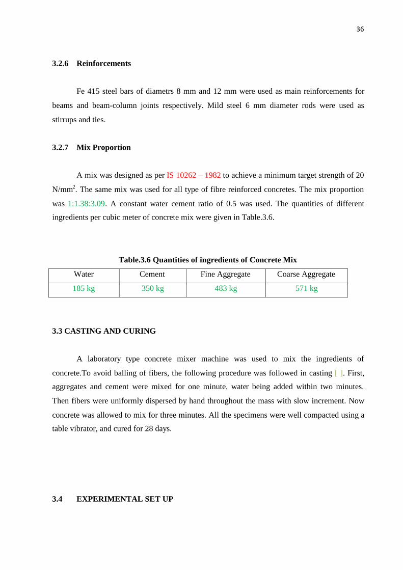
Table.3.6 Quantities of ingredients of Concrete Mix
Water Cement Fine Aggregate Coarse Aggregate
185 kg 350 kg 483 kg 571 kg
3.3 CASTING AND CURING
A laboratory type concrete mixer machine was used to mix the ingredients of
concrete.To avoid balling of fibers, the following procedure was followed in casting [ ]. First,
aggregates and cement were mixed for one minute, water being added within two minutes.
Then fibers were uniformly dispersed by hand throughout the mass with slow increment. Now
concrete was allowed to mix for three minutes. All the specimens were well compacted using a
table vibrator, and cured for 28 days.
3.4 EXPERIMENTAL SET UP
37
This section deals about the experimental set up, spcimen details and testing procedure
of each test planned. The photographs of each test set up also presented in each sub sections.
3.4.1 Workability Studies
The rhelogical properties of fibre reinforced concrete are significant. The large surface
area of fibres tends to restrain flowability and mobility of the mix. Interlocking of fibres and
consequently the formation of fibre balls can be very damaging to the hardened material
properties (M.Ziad Bayasi et.al 1992). There are two important fibre parameters that strongly
influence the degree of damage to concrete workability caused by fibres. It is already
mentioned in the introduction chapter, slump test is not sufficient for measuring the workability
of fibre reinforced concrete. So, both slum test and vee be tests are planned.
3.4.1.1 Slump Test
The slump test was conducted as per IS: 7320 – 1974 The slump was measured in mm.
3.4.1.2 Vee-Bee Test
By using this method, consistency is being found by determining the time required for
transforming b vibration, a concrete specimen in the shape of a conical frustum into a cylinder.
The test was conducted as per Indian Standards.
3.4.1.3 Air Content
The exact air content in concrete is extremely important as it affects the various
parameters of concrete. If the amount of air in a mix differs widely from the design value, the
properties of the concrete may be seriously affected. Too little air results in insufficient
workability and too much air will result in low strength. There are three methods for measuring
air content of fresh concrete namely Gravimetric meter method, volumetric method and
pressure method. Out of which pressure method is perhaps the best method for finding the air
content of fresh concrete because of its superiority and ease of operation.

38
The water meter type has been used in this investigation. The vessel was filled with
concrete, compacted in a standard manner and struck off level. A cover was then clamped in
position. Water was added until the level eas reached ‘0’ mark on the tube of the cover and then
pressure is applied by means of a bicycle pump. The pressure was transmitted to the air
entrained in the concrete, which contracts accordingly. The water level has falled. The pressure
has been incresed to a predetermined value as indicated by a small pressure gauge mounted on
the cover. The glass gauge tube was so calibrated that the percentage of air by volume was
indicated directly.
3.4.2 Mechanical Strength Studies
Plain concrete possesses very low tensile strength, limited ductility and little resistance
to cracking. The presence of micro cracks is responsible for weakness of plain concrete. The
strength characteristics and economic advantages of fibre reinforced concrete are better
compared to conventional concrete. To study the fundamental strength characteristics, the
following studies have been carried out.

39
3.4.2.1 Compressive Strength
According to Indian Standard specifications (IS: 516 – 1959), the compression test on
cubes and cylinders were conducted.
3.4.2.2 Modulus of Elasticity
The modulus of elasticity of concrete is one of the most important mechanical
properties of concrete since it impacts the serviceability and the structural performance of
reinforced concrete structures. The closest approximation to the theoretical modulus of
elasticity derived from a truly elastic response is initial tangent modulus. But it is not always
easily determined from a compession method. In such a case chord modulus of elasticity is
being used. The current method to determine the chord modulus of elasticity of concrete is
Compressometer method. California test 522 (2000) procedure was followed in this study to
eveluate the chord modulus of elasticity. Cylinderical specimens of size 100 mm dia and 300
mm length were casted and cured.
The load was applied continuously without shock. Without interruption, applied loading
and longitudinal strain at pre-designated intervals were taken. The reading interval was fixed as
2kN to permit plotting stress-strain curve if desired. Along the above set of readings, the
following two readings were also monitored and noted. These are
i) The applied load when the longitidinal strain is 50 x 10-6 m/m
ii) The longitudinal strain when the applied load is equal to 40 percent of the
ultimate.
Here, longitudinal strain was defined as the total longitudinal deformation divided by the
effective gauge length. The chord modulus of elasticity was obtained using the formula
(S2 – S1)
E = ----------------------- (3.2)
(C – 0.00005)
Where,
E – Chord modulus of elasticity in Mpa
S2 – Stress corresponding to 40% of ultimate load
40
S1 – Stress corresponding to a longitudinal strain of 50 x 10-6 m/m
C – Longitudinal strain produced by stress S2
3.4.2.2 Split Tensile Strength
Direct measurement of tensile strength of concrete is difficult. One of the indirect
tension test methods is Split tension test. The Split tensile strength test was carried out on the
compression testing machine. The casting and testing of the specimens were done as per IS
5816: 1999.
3.4.2.3 Modulus of Rupture
The extreme fibre stress calculated at the failure of specimen is called Modulus of
rupture. It is also an indirect measure to predict the tensile strength of concrete. Flexural
strength test was conducted as per recommendations IS: 516 – 1959. In flexural strength test,
beams of size 10 x 10 x 50 cm were casted.
3.4.2.5 Shear Strength
So far mechanical strength properties are representing the compressive and tensile
strength of concrete only. No much work on shear strength of concrete was reported by
researchers. But fibre reinforced concrete possesses significant improvement in shear strength
(Baruah.P and Talukdar 2007). Bairagi N.K et.al (2001) proposed a method to determine the
shear strength of fibre reinforced concrete.
Based on the literature, L-shaped shear test specimens were prepared from 150 mm
cubes by inserting a wooden block of 90 mm x 60 mm in cross section and 150 mm high into
the cube moulds before casting of concrete. The details of the shear test specimen are shown in
Fig.3.24. All the test specimens were casted and cured for 28 days. The loading arrangement
for shear test is shown in Fig.3.25. The speciemns were placed as shown in Fig.3.26 on
compression testing machine. A 150 x 85 x 10 mm size MS plate was placed on 90 mm face of
leftside portion. Mild steel bar of 12 mm diameter was placed over the centre of the plate.
Another 22 mm diameter MS bar was placed at the edge of the plate. Ovar these bars, another

41
MS plate of size 150 x 110 x 10 mm was placed. Load was applied on the top plate which
forms shear plane below the centre of 22 mm diameter bar. The loading was continued until the
specimen failure. The shear strength was obtained using
P
fs = ----
A
Where,
fs – Shear strength
P – Applied compression load
A – Shearing area
Fig. 3.24 Details of ‘L’ Shaped Specimen
Fig3.25 Loading Arrangement of Shear Test

42
Fig.3.26 Shear Test on ‘L’Specimen
3.4.3 Structural Behaviour Studies
This section provides the details about experimental methodology, test set up, detailing
of specimens which were casted to study the structural properties such as ductility, energy
absorption of beam and beam-column joint specimens under static and cyclic loading. Based on
the above mentioned elaborative mechanical strength studies, two volume fractions such as
0.5% and 1.0% of all the fibres were selected and further used in this section.
3.4.3.1Static Flexural Behaviour of Beams
The benefit of addition of discrete fibres on the flexural strength of reinforced concrete
beams has been investigated in this section. Based on the experimental investigations, load vs
midspan deflection and moment vs rotation curves have been drawn. Seismic critical
parameters such as ductiltiy, energy absorption capacity and stiffness degradation at three
salient points such as first cracking, first yielding and ultimate points. This section is giving the
specimen details including reinforcement detailing; loading sequence and experimental set up
are discussed.
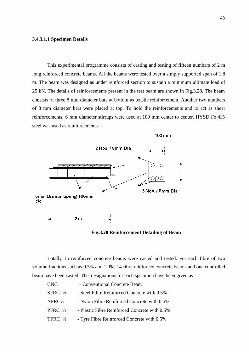
43
3.4.3.1.1 Specimen Details
This experimental programme consists of casting and testing of fifteen numbars of 2 m
long reinforced concrete beams. All the beams were tested over a simply supported span of 1.8
m. The beam was designed as under reinforced section to sustain a minimum ultimate load of
25 kN. The details of reinforcements present in the test beam are shown in Fig.3.28. The beam
consists of three 8 mm diameter bars at bottom as tensile reinforcement. Another two numbers
of 8 mm diameter bars were placed at top. To hold the reinforcements and to act as shear
reinforcements, 6 mm diameter stirrups were used at 100 mm center to center. HYSD Fe 415
steel was used as reinforcements.
Fig.3.28 Reinforcement Detailing of Beam
Totally 15 reinforced concrete beams were casted and tested. For each fibre of two
volume fractions such as 0.5% and 1.0%, 14 fibre reinforced concrete beams and one controlled
beam have been casted. The designations for each specimen have been given as
CNC – Conventional Concrete Beam
SFRC ½ - Steel Fibre Reinforced Concrete with 0.5%
NFRC½ - Nylon Fibre Reinforced Concrete with 0.5%
PFRC ½ - Plastic Fibre Reinforced Concrete with 0.5%
TFRC ½ - Tyre Fibre Reinforced Concrete with 0.5%

44
CFRC ½ - Coir Fibre Reinforced Concrete with 0.5%
SCFRC½ - Sugarcane Fibre Reinforced Concrete with 0.5%
RFRC ½ - Rice Husk Fibre Reinforced Concrete with 0.5%
SFRC1- Steel Fibre Reinforced Concrete with 1.0%
NFRC1 - Nylon Fibre Reinforced Concrete with 1.0%
PFRC 1 - Plastic Fibre Reinforced Concrete with 1.0%
TFRC 1 - Tyre Fibre Reinforced Concrete with 1.0%
CFRC 1 - Coir Fibre Reinforced Concrete with 1.0%
SCFRC1 - Sugarcane Fibre Reinforced Concrete with 1.0%
RFRC 1 - Rice Husk Fibre Reinforced Concrete with 1.0%
3.4.3.1.2 Specimens Casting
All the beams specimens were cast in steel moulds. Laboratory type mixer machine was
used to mix the ingredients of concrete. To avoid balling effect of fibers, the following
procedure was followed in casting. First, aggregates and cement were put and allowed to mix
for one minute and water was added within two minutes. Then, fibers were uniformly dispersed
throughout the mass with slow increment. Finally, concrete was allowed to mix for three
minutes. All the specimens were well compacted using table vibrator. The specimens were
demolded after one day and then placed in a curing tank for 28 days of curing. For 12 hours
prior to the testing, the specimens were allowed to air dry in laboratory.
3.4.3.1.3 Test Set Up
Tests were carried out at room temperature and as per the Indian standards. Structural
properties are ascertained by conducting middle third loading test. The testing arrangement is
shown in Fig.3.29. Four point bending was applied on reinforced concrete beams of beam span
1.8 m through hydraulic jack of capacity 100kN. The specimens were placed on a simply
supported arrangement of 100 T Loading frame. The beams were suitably instrumented for
measuring deflections at several locations including the midspan deflection with dial gauges
and LVDTs. To avoid the excessive deformation at the support locations, additional dial gauges

45
were placed at the top and bottom faces of ends. DEMEC (Demoundable mechanical strain
gauge) was used to measure the concrete strain readings at top as well as the bottom fibre on
mid section of the beam.
Fig.3.29 Loading Arrangement of Flexural Test
Fig.3.30 Experimental Set Up
First yielding of steel is very much important in structural characterization particularly
in ductiltiy calculation. To read the strain values of main steel reinforcement, electrical strain
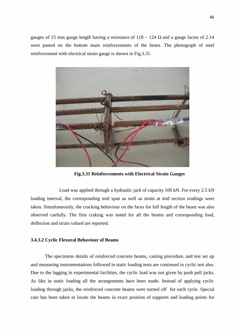
46
gauges of 15 mm gauge length having a resistance of 118 – 124 Ωand a gauge factor of 2.14
were pasted on the bottom main reinforcements of the beam. The photograph of steel
reinfrocement with electrical strain gauge is shown in Fig.3.31.
Fig.3.31 Reinforcements with Electrical Strain Gauges
Load was applied through a hydraulic jack of capacity 100 kN. For every 2.5 kN
loading interval, the corresponding mid span as well as strain at mid section readings weer
taken. Simultaneously, the cracking behaviour on the faces for full length of the beam was also
observed caefully. The first craking was noted for all the beams and corresponding load,
deflection and strain valued are reported.
3.4.3.2 Cyclic Flexural Behaviour of Beams
The specimens details of reinforced concrete beams, casting procedure, and test set up
and measuring instrumentations followed in static loading tests are continued in cyclic test also.
Due to the lagging in experimental facilities, the cyclic load was not given by push pull jacks.
As like in static loading all the arrangements have been made. Instead of applying cyclic
loading through jacks, the reinforced concrete beams were turned off for each cycle. Special
care has been taken to locate the beams in exact position of supports and loading points for
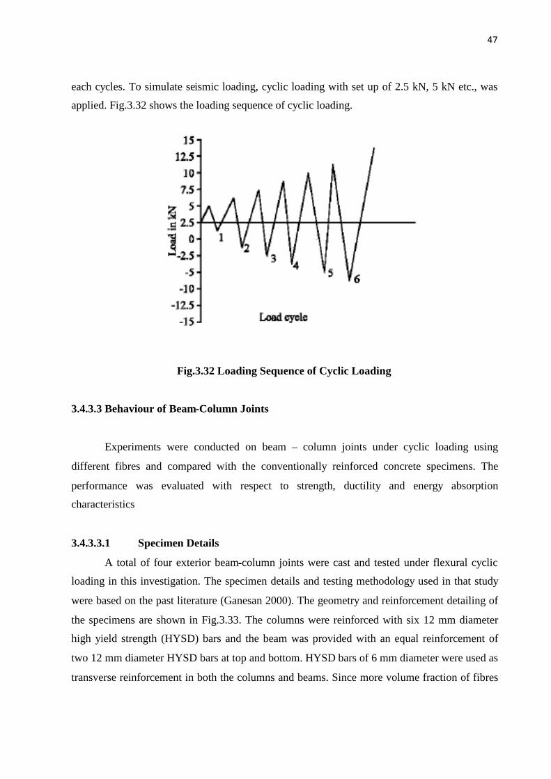
47
each cycles. To simulate seismic loading, cyclic loading with set up of 2.5 kN, 5 kN etc., was
applied. Fig.3.32 shows the loading sequence of cyclic loading.
Fig.3.32 Loading Sequence of Cyclic Loading
3.4.3.3 Behaviour of Beam-Column Joints
Experiments were conducted on beam – column joints under cyclic loading using
different fibres and compared with the conventionally reinforced concrete specimens. The
performance was evaluated with respect to strength, ductility and energy absorption
characteristics
3.4.3.3.1 Specimen Details
A total of four exterior beam-column joints were cast and tested under flexural cyclic
loading in this investigation. The specimen details and testing methodology used in that study
were based on the past literature (Ganesan 2000). The geometry and reinforcement detailing of
the specimens are shown in Fig.3.33. The columns were reinforced with six 12 mm diameter
high yield strength (HYSD) bars and the beam was provided with an equal reinforcement of
two 12 mm diameter HYSD bars at top and bottom. HYSD bars of 6 mm diameter were used as
transverse reinforcement in both the columns and beams. Since more volume fraction of fibres

48
than 1% does not yield good workability as well as leads to strength reduction, it was restricted
to 1%.
Fig.3.33 Reinforcement Detailing of Beam-Column Joint
Fig.3.34 Fibre Portion in Beam – Column Joint
3.4.3.3.2 Testing of Specimens

49
Tests were carried out at room temperature in a universal testing machine (UTM) of 100
t capacity. As shown in Fig.3.35, to simulate the column axial load as well as to maintain the
position, vertically placed specimens were subjected to a constant axial load of 75 kN which
consists of 20 percent of the axial load capacity of the column. A dial gauge was provided at
the free end of the beam to measure deflection and DEMEC gauge pellets were pasted at the
top and bottom of the junction as well as at centre of the column to record the strains. The beam
was loaded at free end through a hydraulic jack and the corresponding deflection and strain
readings were taken. To read the intensity of loading precisely, load cell with a least count of
0.01 kN was used. The sequence of cyclic loading is also shown in Fig.3.36. The increment of
loading selected was 4 kN. Load-Deflection and Moment-Curvature curves were plotted based
on the experimental readings
Fig.3.35 Loading Arrangement of Beam – Column Joint

50
Fig.3.36 Loading Sequence of Beam – Column Joint Test
Fig.3.37 Reinforcement Detailing of Beam – Column Joint
Fig.3.38 Casting of Beam – Column Joint

51
Fig.3.39 Testing of Beam – Column Joint
Fig.3.40 Final Shape of Beam – Column Joint
52
CHAPTER 4
ANALYTICAL INVESTIGATION
4.1 INTRODUCTION
Since the focus of the present study is based on the locally available waste materials, validation
of experimental results through some means will give more confident to future researchers. For
this purpose, a three dimensional non-linear finite element modeling and analysis has been
carried out for different concrete beams using commercial software ANSYS 10. The fraction of
the entire volume of the fibre present along the longitudinal axis of the reinforced concrete
beams alone has been modeled explicitly as it is expected that these fibres would contribute to
the mobilization of forces required to ustain the applied loads across the nterfaces through their
bridging action (Padmarajaiah S.K and Ananth Ramaswamy 2002). The load – displacement
curve obtained for different type of concrete beams from ANSYS 10 are compared with
experimental curves.
One of the important advantages of using fibres in seismic design of reinforced concrete beams
is to limit the damage at critical locations of the structures by improving their energy
absorption and ductility characteristics. Experimental results of cyclic loading tests have
repoted the enhancement in seismic parameters. To facilitate the quantification of damage in
analysis and design, a numerical damage is a valuable tool. Two well known damage index
models have been selected for the computation of damage index, namely the one proposed by
Kratzig et.al (1989) and the simplified damage model proposed by Sreekala S et.al (2007).
Based on the static and cyclic experimental results, damage indices have been computed and
compared.
4.2 Finite Element Modelling Using ANSYS 10
53
The step-by-step procedure of FE analysis has been briefly described here.
1. The structure has been descretized into finite elements. The geometry, loading and
boundary conditions have been defined. The concrete has been modeled using
SOLID65 elements; the steel reinforcements (fibers / prestressing steel (S) / high
strength deformed bars (HYSD) have been modeled using LINK8 elements. SOLID65,
LINK8 are the elements available in the ANSYS 10 element library.
2. The number of load steps and sub-steps required has been specified to capture the
nonlinearity effectively. In ANSYS 10 program, the load steps and sub-steps is
specified with a ‘time’ parameter established at the end of each step. At each load
increment, the stiffness matrix will get updated in the Newton Raphson iteration
procedure in the ANSYS.
3. The program continues the iteration process until the convergence criteria are satisfied
or the maximum number of iteration specified for the sub-step is reached. If the
convergence criteria are satisfied, the next increment of load is applied and the
procedure is repeated. Otherwise, the unbalanced load is applied back to the structure
and the iterations continued. If the maximum iterations are exceeded, the program
terminates.
The FE model used in this finite element analysis is shown in Fig.4.3.1. The full length
beam has been modeled as SOLID 65 element. The mesh consisted of 20 concrete elements
along the longitudinal axis, 4 elements across the width and 6 element along the depth. Studies
by Bazzant and Oh (1983) and Bazant and Cedolin (1993) indicated that the smallest element
dimension in FE analysis is fixed based on the size of coarse aggregate used. So, the mesh size
has been fixed as 25mm which is greater than the maximum size of coarse aggregate used in
the experimental investigation. The test results of cylinder compressive strength and split
tensile strength based on the companion specimens cast and tested along the reinforced
concrete beams were used as material properties of concrete in ‘ANSYS’.
To obtain the crack pattern of the beams at the end, shear transfer co-efficients in
opening is assumed as 0.2 and in closing is assumed as 0.9. The remainig parameters such as
Hydrostatic stress state, Bi-axial compressive stress, Uni-axial tensile stress and Tensile
cracking fracture are assumed to be the default values have been set so as to represent William

54
and Warnke model (1975). In ANSYS, smeared representation of crack is used in ‘SOLID 65’.
Before cracking concrete, concrete is assumed to an elastic isotropic material. After cracking,
concrete is assumed to be orthotropic having stiffness based on a bi-linear softening stress-
strain response. The steel reinforcements such as stirrups, deformed main bars and hanger bars
have been modeled as ‘LINK 8’three dimensional truss element. Addition of fibres in concrete
increases the post-cracking stiffness of the concrete through the bridging of fibres across the
crack interfaces. This induces the resistance to the ctack opening when the concrete strain is
greater than six times the ultimate strain. For that fibres have been modeled discretely.
The effectiveness of fibres in increasing the tensile strength of the concrete, at least
partially depends on the number of fibres per cross sectional area of concrete (Padmarajaiah
S.K and Ananth Ramaswamy 2002). The fraction of the entire volume of the fibre present
along the longitudinal axis alone was modeled explicity as it was expected to contribute to the
mobilization of forces required to sustain the applied loads after concrete cracking and provide
resistance to crack propogation. Another important point is during the casting of fibre
reinforced concrete , due to the vibration process fibres in concrete tend to settle down and
reorient in horizontal planes. Hence the area of discrete reinforcement representing the fibre
(Af) is arrived based on the equation
Af = α’ Vf Act (4.32)
Where, α’ is the Orientation factor which is assumed as 0.64 for 2D and 3D
orientation of fibres in beam (Souroushian and Lee 1990). Act is the tributary area of the
concrete over which the fibre present. The tributary area concept is illustrated in Fig.4.3.2. The
elements lying in the boundaries carry half of the area of fibres used in the interior of the FE
mesh. Rate independent multi-linear isotropic hardening option with Von-Mises yield creterion
has been used to define the material property of fibres. The elasto-plastic material behaviour of
the fibres was given as input into ‘ANSYS’.
4.3 Evaluation of Damage Indices
Damage indices are the valuable tools which provide a means by which different design
or retrofit options can be compared objectively. Among the different models proposed by
earlier researchers, the followint two has been selcted in this study.
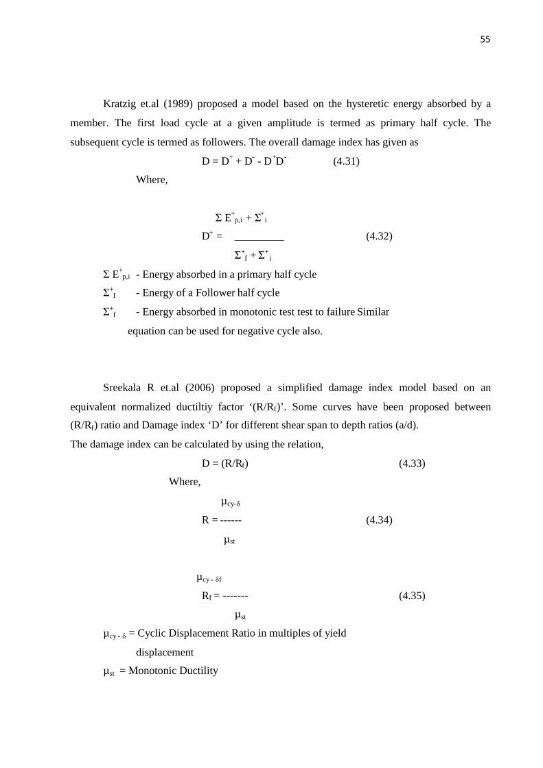
55
Kratzig et.al (1989) proposed a model based on the hysteretic energy absorbed by a
member. The first load cycle at a given amplitude is termed as primary half cycle. The
subsequent cycle is termed as followers. The overall damage index has given as
D = D+ + D- - D+D- (4.31)
Where,
ΣE+p,i + Σ+
i
D+ = _________ (4.32)
Σ+f +Σ+
i
ΣE+p,i - Energy absorbed in a primary half cycle
Σ+I - Energy of a Follower half cycle
Σ+f - Energy absorbed in monotonic test test to failure Similar
equation can be used for negative cycle also.
Sreekala R et.al (2006) proposed a simplified damage index model based on an
equivalent normalized ductiltiy factor ‘(R/Rf)’. Some curves have been proposed between
(R/Rf) ratio and Damage index ‘D’ for different shear span to depth ratios (a/d).
The damage index can be calculated by using the relation,
D = (R/Rf) (4.33)
Where,
µcy-δ
R = ------ (4.34)
µst
µcy - δf
Rf = ------- (4.35)
µst
µcy - δ= Cyclic Displacement Ratio in multiples of yield
displacement
µst = Monotonic Ductility

56
Fig.4.3.3 Proposed Curve for Damage Index (Sreekala R et.al)
The value of (R/Rf) for conventional and fibre reinforced concrete beams have been
calculated from the experimental hysteretic curves. For the corresponding (R/Rf) value,
Damage indices have been obtained from the Fig.4.3.3. This will give the clear indication about
the increment or reduction in damage of structural element under unanticipated loading
conditions.

57
CHAPTER 5
RESULTS AND DISCUSSIONS
5.1 INTRODUCTION
The results obtained from the above elaborative experimental as well as analytical
investigations are discussed in this chapter. Initially the workability properties such as slump
value, vee-bee time and air content percentage have been discussed. Then the results of
mechanical strength properties such as cube compressive strength, cylinder compressive
strength, split tensile strength, modulus of rupture, modulus of elasticity, shear strength and
impact energy have discussed. Comparision of experimental and predicted values of proposed
expressions has been made for all the fibre concrete mixes. Even the natural fibres have given
comparable strength properties, durability of such natural fibres are questionable. So the natural
fibres have been allowed to react with concrete for about two years under alternative wetting
and drying conditions. After two years they have been taken from the concrete and subjected to
microstructural SEM study. The results obtained from the investigations are discussed. Next
the structural properties of conventionally reinforced and fibre reinforced concrete beams under
static loading are discussed. The critical seismic parameters such as ductility, energy absorption
capacity and stiffness degradation along both system and section are discussed. The
experimental results are validated analytically by two means. One of the ways is validationg the
ultimate moment obtained from the moment - rotation curves using a mechanical model which
was proposed by earlier researchers. The another one is a finite element analysis which has
been conducted using ANSYS software. Apart from these analyses, a inverse type finite
element analyses has been carried out using MATLAB and the results are discussed in the
subsequent heading. Then the damage indices based on the expressions proposed by earlier
researchers for different fibre reinforced concrete beams have been evaluated from the
experimental results and discussed. Finally the results obtained from the beam – column joint
test are discussed.
5.2 Workability Properties
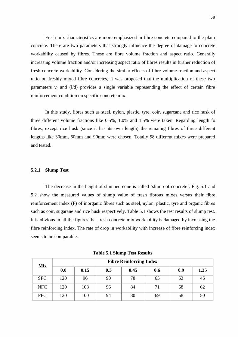
58
Fresh mix characteristics are more emphasized in fibre concrete compared to the plain
concrete. There are two parameters that strongly influence the degree of damage to concrete
workability caused by fibres. These are fibre volume fraction and aspect ratio. Generally
increasing volume fraction and/or increasing aspect ratio of fibres results in further reduction of
fresh concrete workability. Considering the similar effects of fibre volume fraction and aspect
ratio on freshly mixed fibre concretes, it was proposed that the multiplication of these two
parameters vf and (l/d) provides a single variable represending the effect of certain fibre
reinforcement condition on specific concrete mix.
In this study, fibres such as steel, nylon, plastic, tyre, coir, sugarcane and rice husk of
three different volume fractions like 0.5%, 1.0% and 1.5% were taken. Regarding length fo
fibres, except rice husk (since it has its own length) the remainig fibres of three different
lengths like 30mm, 60mm and 90mm were chosen. Totally 58 different mixes were prepared
and tested.
5.2.1 Slump Test
The decrease in the height of slumped cone is called ‘slump of concrete’. Fig. 5.1 and
5.2 show the measured values of slump value of fresh fibrous mixes versus their fibre
reinforcement index (F) of inorganic fibres such as steel, nylon, plastic, tyre and organic fibres
such as coir, sugarane and rice husk respectively. Table 5.1 shows the test results of slump test.
It is obvious in all the figures that fresh concrete mix workability is damaged by increasing the
fibre reinforcing index. The rate of drop in workability with increase of fibre reinforcing index
seems to be comparable.
Table 5.1 Slump Test Results
Fibre Reinforcing IndexMix
0.0 0.15 0.3 0.45 0.6 0.9 1.35
SFC 120 96 90 78 65 52 45
NFC 120 108 96 84 71 68 62
PFC 120 100 94 80 69 58 50

59
TFC 120 95 82 68 53 42 35
CFC 120 96 85 70 59 52 42
SCFC 120 92 80 64 50 42 36
RFC 120 95 82 74 - - -
At specific fibre reinforing index value, tyre fibre seems to give higher slump value.
Next to tyre, sugarcane, plastic, steel and coir have given the higher slumps respectively. Due
to higher surface area, tyre and plastic fibres possessed less workability in incresed fibre
reinforcing index values. Also because of water absorption capabilty, organic natural fibres
have given the lesser workability. Though rice husk is a organic fibre, its less specific area did
not affect the workability significantly while comparing with others. Among all the fibres,
nylon possesed higher workability by having less water absorption capability as well as less
surface area.
Fig 5.1 Comparision of FRI and Slump of Inorganic Fibres
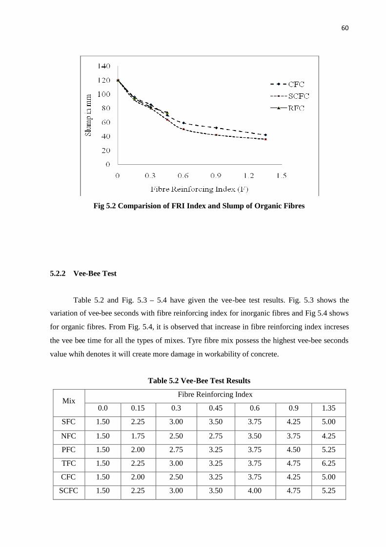
60
Fig 5.2 Comparision of FRI Index and Slump of Organic Fibres
5.2.2 Vee-Bee Test
Table 5.2 and Fig. 5.3 – 5.4 have given the vee-bee test results. Fig. 5.3 shows the
variation of vee-bee seconds with fibre reinforcing index for inorganic fibres and Fig 5.4 shows
for organic fibres. From Fig. 5.4, it is observed that increase in fibre reinforcing index increses
the vee bee time for all the types of mixes. Tyre fibre mix possess the highest vee-bee seconds
value whih denotes it will create more damage in workability of concrete.
Table 5.2 Vee-Bee Test Results
Fibre Reinforcing IndexMix
0.0 0.15 0.3 0.45 0.6 0.9 1.35
SFC 1.50 2.25 3.00 3.50 3.75 4.25 5.00
NFC 1.50 1.75 2.50 2.75 3.50 3.75 4.25
PFC 1.50 2.00 2.75 3.25 3.75 4.50 5.25
TFC 1.50 2.25 3.00 3.25 3.75 4.75 6.25
CFC 1.50 2.00 2.50 3.25 3.75 4.25 5.00
SCFC 1.50 2.25 3.00 3.50 4.00 4.75 5.25

61
RFC 1.50 1.75 2.00 2.25 3.25 3.75 4.50
Vee bee seconds for steel fibre concrete stated from 1.5 seconds for zero fibre reinforcing index
to 4.5 seconds for fibre reinforcing index 1.35. Nylon fibre concrete possesses lowest vee bee
seconds values while comparing with other fibres. As like in slump test, here also tyre fibre
concrete yields more vee bee seconds. Though it has lesser value at lower fibre reinforcing
index values, it rearches the highest at higher fibre reinforcing indices. The remaining inorganic
fibre called plastic fibre shows the intermideate value of vee bee seconds.
Fig 5.3 Comparision of FRI and Vee-Bee sec of Inorganic Fibres
While considering the organic fibres, rice husk did not give very big damage to vee
seconds deviation. But sugarcane starts from 1.50 seconds for zero fibre reinforcing index and
ends at 5.25 seconds for fibre reinforcing index of 1.35. Coir fibre shows the intermediate value
of vee bee seconds. So from the vee bee test results also it is proved that fibres having large
surface area and higher water absorption capacity tends the concrete to less workable, where as
fibres like nylon having less surface area and water absorbing capability did not affect much
than others. Anyway it is also observed that addition of any fibre damages the workability from
150% to 250%.

62
Fig 5.4 Comparision of FRI and Vee-Bee sec of Organic Fibres
5.2.3 Air Content
The experimental results of pressure method which was conducted to measure the air
content are shown in Fig.5.5 – 5.4. There is no any direct relation for air content with fibre
reinforcing indeices. So, in this study comparisions were made with volume fractions and
length of fibres. From the Figures, it can be known that increase in volume fraction of any fibre
increases the air content values. But length of fibre concrened, decrese in length of fibres in
thinner fibres increases the air content where as in thicker fibres increase in length of fibres
increases the percentage of air content.
Among the seven fibres used, steel, nylon, coir and sugarcane are compritively thinner
than the remaining fibres such as plastic, tyre and sugarcane. For constant volume fraction,
decreasing the length of thinner fibres increases the air content. This may be due to the increase
in number of fibres per unit volume of concrete area. Air content of conventional concrete was
measured as 2%. This is increased upto 4.8% for steel fibres of 30mm length and 1.5% volume
fraction. For nylon fibres, air content increses upto 4.6%, for coir fibres upto 5.2%, and for rice
husk upto 4.6%.

63
Fig 5.5 Comparision Between Volume Fraction of 30 mm long
Thin Fibres and Air Content
Similarly in thick fibres also volume of fibres in concrete increases the air content of the
concrete. Though at the lower volume fractions, tyre and sugarcene fibres influenced the air
content comparitively lightly, at higher volume fraction it exceeds the air conten of plastic fibre
concrete. The air content of fibre concrete deviates from 50% to 140% from conventional
concrete air content. Similary for 60mm length and 90 mm length fibres, effect of volume
fraction of fibres on air content percentage are shown in Fig. 5.7 to 5.10. In all the figures, at
any particular length of fibre, volume fraction increases the air content significantly.

64
Fig 5.6 Comparision between Volume Fraction of 30 mm long Thick Fibres and Air
Content
Fig 5.7 Comparision between Volume Fraction of 60mm long Thin Fibres and Air
Content
Fig 5.8 Comparision between Volume Fraction of 60mm long Thick Fibres and Air
Content
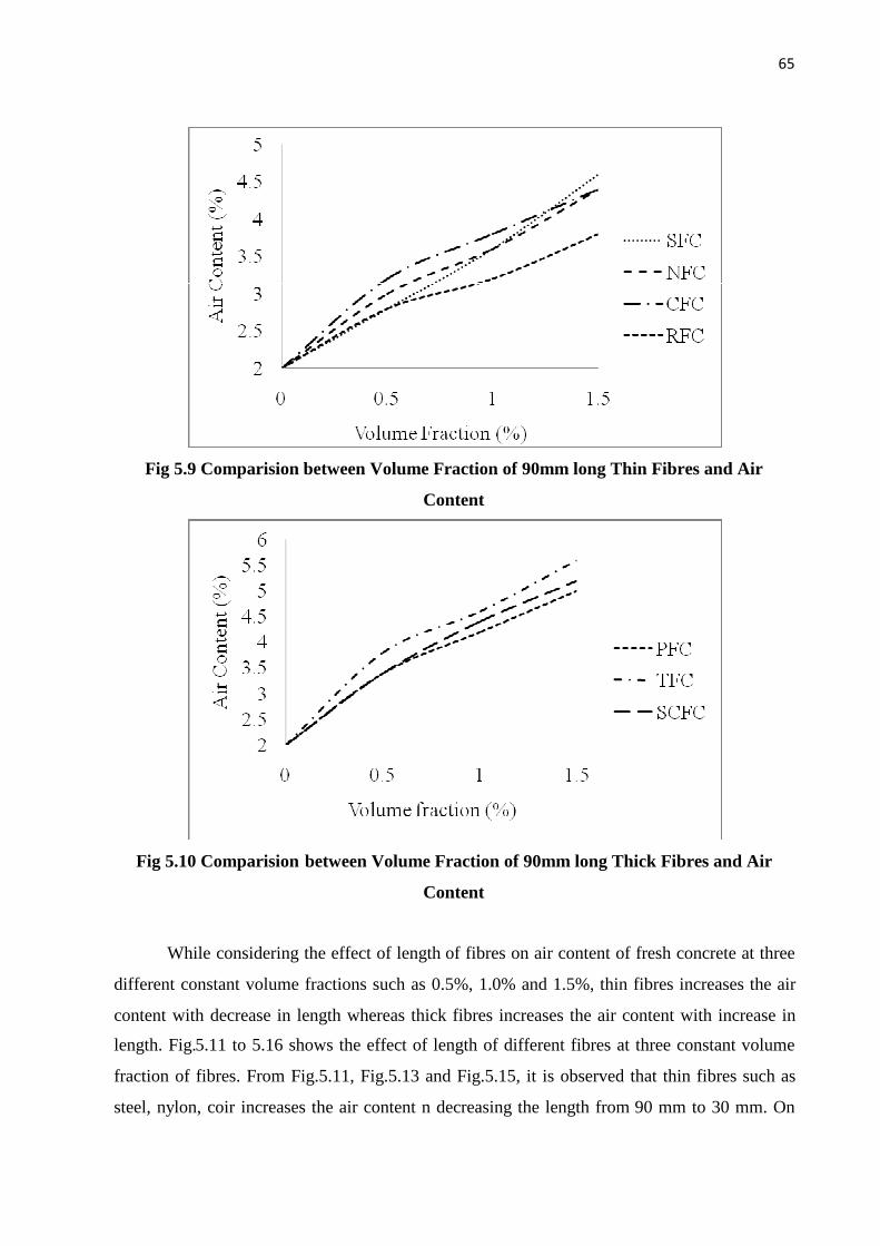
65
Fig 5.9 Comparision between Volume Fraction of 90mm long Thin Fibres and Air
Content
Fig 5.10 Comparision between Volume Fraction of 90mm long Thick Fibres and Air
Content
While considering the effect of length of fibres on air content of fresh concrete at three
different constant volume fractions such as 0.5%, 1.0% and 1.5%, thin fibres increases the air
content with decrease in length whereas thick fibres increases the air content with increase in
length. Fig.5.11 to 5.16 shows the effect of length of different fibres at three constant volume
fraction of fibres. From Fig.5.11, Fig.5.13 and Fig.5.15, it is observed that thin fibres such as
steel, nylon, coir increases the air content n decreasing the length from 90 mm to 30 mm. On

66
other hand, if thick fibres are consideed, plastic, tyre and sugarcane fibres increases the air
content while increasing the length of fibres. While observing the graphs, the decay pattern of
all the fibres of three different lengths at three volume fractions is nearly same.
Fig 5.11 Comparision between Length of Thin Fibres at 0.5% Volume Fraction and Air
Content
Fig 5.12 Comparision Between Length of Thick Fibres at 0.5% Volume Fraction and Air
Content

67
Fig 5.13 Comparision between Length of Thin Fibres at 1.0% Volume Fraction and Air
Content
Fig 5.14 Comparision Between Length of Thick Fibres at 1.0% Volume Fraction and Air
Content

68
Fig 5.15 Comparision between Length of Thin Fibres at 1.5% Volume Fraction and Air
Content
Fig 5.16 Comparision between Length of Thick Fibres at 1.5% Volume Fraction and Air
Content
5.3 Mechanical Strength Studies
To evaluate the mechanical strength characteristics of concrete reinforced with different
fibre materials, detailed experimental investgation was carried out and the results are discussed
in the forthcoming sections. Totally eight important characteristics are discussed. Along with

69
the fundamental material strength parameters such as cube compressive strength, cylinder
compressive strength, split tensile strength, modulus of rupture, modulus of elasticity additional
strength parameters such as shear strength and impact energy at both first crack as well as
ultimate stages are also studied. Effect of type of fibre and fibre reinforcing index which was
calculted by multiplying the volume fraction of fibres and aspect ratio of fibres on the
abovementioned parameters are also discussed.
Based on the experimental results, regression analysis was carried out to form some
relations between different parameters and equtions are also proposed. The proposed equations
include the relation between each parameter with cyclinder compressive strength which is the
most common strength parameter obtained in all the works and the relation between the
parameters and fibre reinforcing index values. Using the proposed regression models, one can
easily compute all the strength parameters by means of basic concrete property known as
compressive strength. Another application of these parameters is in analytical invesigations. In
both mechanical model and numerical finite element model formulation, the strength
characteristics are used to assess the flexural performance of different structural members.
5.3.1 Cube Compressive Strength
Totally 174 cube specimens of size 150 mm with 58 mixes were casted and tested.
Three volume fractions were considered for six fibres of three different lengths and one fibre
of constant length. Results for compressive strength based on the average values of three test
data for all mixtures are presented fibre wise from Table 5.5 to 5.11. Based on the experimental
results a linear regression model is proposed for each fibre concrete. A sample comparision
graph for steel fibre concrete is plotted to study the effect of fibre reinforcing index on
conventional concrete stength which is shown in Fig. 5.17. The first term of the model shows
the contribution of controlled concrete strength and the second term represents the contribution
of fibre dosage and fibre geometry. The predicted value of the compressive strength of different
mixes has been compared with the experimental results in Table 5.4.

70
Fig. 5.17 Relation between Cube Compressive Strength of Steel Fibre Concrete and Fibre
Reinforcing Index
Table 5.4 Predicted Regression Models for Cube Compressive Strength of Different Fibre
Concretes
Type of Fibre Concrete Predicted Model
Steel Fibre Concrete fcuf = 4.43(FRI)+fcu
Nylon Fibre Concrete fcuf = 2.83(FRI)+fcu
Plastic Fibre Concrete fcuf = 2.43 (FRI)+fcu
Tyre Fibre Concrete fcuf = 1.80 (FRI)+fcu
Coir Fibre Concrete fcuf = 1.92 (FRI)+fcu
Sugarcane Fibre Concrete fcuf = 1.97 (FRI)+fcu
Rice Husk Fibre Concrete fcuf = 1.51 (FRI)+fcu
From the proposed equations, it is observed that at a particular fibre reinforcing
index value, steel fibres contributed more in compressive strength than others. Next to steel
fibres, the contributors are nylon, plastic, sugarcene, coir, tyre and rice husk. The predicted
values of compressive strength for different fibre concretes have been compared with the
experimental results. The comparision indicates that the proposed compressive strength model
predicts the test data accurately.

71
Table 5.4 also shows the percentage increase in compressive strength of fibre concrete
over conventional concrete. Table 5.5 shows the compressive strength values of steel fibre
concrete. The compressive strength of SFC with fibre reinforcing index 0.45 (Volume fraction
= 0.5% and Aspect ratio = 90) shows the highest value. It is nearly 20% increment over
conventional concrete. While considering the different volume fractions, 0.5% only gives the
higher value. Increase in the volume fraction reduces the increment of compressive strength for
higher Aspect ratio. It may be due to the balling effect during the concrete mixing. While
considering the Aspect ratios, increase in Aspect ratio of fibres increases the stremgth almost
for al the mixes. But if 1.5% volume fraction is used, the strength of higher Aspect ratio fibres
has been reduced than the strength of lower Aspect ratio.
Table 5.5 Compressive Strength of Steel Fibre Concrete
fcuf in MPaType of
Concrete
Volume
fraction
(vf) in %
Aspect
ratio
(l/d)
FRI
(vf x l/d) Expt. Model
Model/
Expt.
CC - - - 27.33 27.33 1
0.5% 30 0.15 27.95 28 1.01
0.5% 60 0.30 30.52 28.66 0.94
0.5% 90 0.45 32.88 29.33 0.9
1.0% 30 0.30 29.98 28.66 0.96
1.0% 60 0.60 30.54 29.99 0.99
1.0% 90 0.90 31.67 31.32 0.99
1.5% 30 0.45 29.65 29.33 0.99
1.5% 60 0.90 31.24 31.32 1.01
SFC
1.5% 90 1.35 30.78 33.32 1.09
Table 5.6 Compressive Strength of Nylon Fibre Concrete
fcu in MPaType of
Concrete
Volume
fraction
(vf) in %
Aspect
ratio
(l/d)
FRI
(vf x l/d) Expt. Model
Model/
Expt.
CC - - 0 27.33 27.33 1
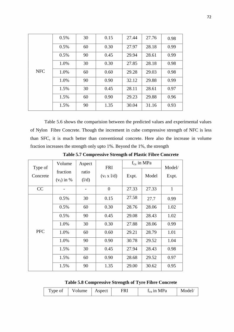
72
0.5% 30 0.15 27.44 27.76 0.98
0.5% 60 0.30 27.97 28.18 0.99
0.5% 90 0.45 29.94 28.61 0.99
1.0% 30 0.30 27.85 28.18 0.98
1.0% 60 0.60 29.28 29.03 0.98
1.0% 90 0.90 32.12 29.88 0.99
1.5% 30 0.45 28.11 28.61 0.97
1.5% 60 0.90 29.23 29.88 0.96
NFC
1.5% 90 1.35 30.04 31.16 0.93
Table 5.6 shows the comparision between the predicted values and experimental values
of Nylon Fibre Concrete. Though the increment in cube compressive strength of NFC is less
than SFC, it is much better than conventional concrete. Here also the increase in volume
fraction increases the strength only upto 1%. Beyond the 1%, the strength
Table 5.7 Compressive Strength of Plastic Fibre Concrete
fcu in MPaType of
Concrete
Volume
fraction
(vf) in %
Aspect
ratio
(l/d)
FRI
(vf x l/d) Expt. Model
Model/
Expt.
CC - - 0 27.33 27.33 1
0.5% 30 0.15 27.58 27.7 0.99
0.5% 60 0.30 28.76 28.06 1.02
0.5% 90 0.45 29.08 28.43 1.02
1.0% 30 0.30 27.88 28.06 0.99
1.0% 60 0.60 29.21 28.79 1.01
1.0% 90 0.90 30.78 29.52 1.04
1.5% 30 0.45 27.94 28.43 0.98
1.5% 60 0.90 28.68 29.52 0.97
PFC
1.5% 90 1.35 29.00 30.62 0.95
Table 5.8 Compressive Strength of Tyre Fibre Concrete
Type of Volume Aspect FRI fcu in MPa Model/

73
Concrete fraction
(vf) in %
ratio
(l/d)
(vf x l/d)Expt. Model
Expt.
CC - - 0 27.33 27.33 1
0.5% 30 0.15 27.34 27.6 0.99
0.5% 60 0.30 28.12 27.87 1
0.5% 90 0.45 28.58 28.14 1.01
1.0% 30 0.30 27.88 27.87 1
1.0% 60 0.60 28.52 28.41 1
1.0% 90 0.90 29.68 28.95 1.02
1.5% 30 0.45 27.88 28.14 0.99
1.5% 60 0.90 28.94 28.95 0.99
TFC
1.5% 90 1.35 29.12 29.76 0.97
Table 5.9 Compressive Strength of Coir Fibre Concrete
fcu in MPaType of
Concrete
Volume
fraction
(vf) in %
Aspect
ratio
(l/d)
FRI
(vf x l/d) Expt. Model
Model/
Expt.
CC - - 0 27.33 27.33 1
0.5% 30 0.15 27.34 27.6 0.99
0.5% 60 0.30 27.96 27.87 1
0.5% 90 0.45 28.45 28.14 1.01
1.0% 30 0.30 27.28 27.87 0.97
1.0% 60 0.60 28.74 28.41 1.01
1.0% 90 0.90 30.54 28.95 1.05
1.5% 30 0.45 28.21 28.14 1
1.5% 60 0.90 29.44 28.95 1.01
CFC
1.5% 90 1.35 28.62 29.76 0.96
Table 5.10 Compressive Strength of Sugarcane Fibre Concrete
Type of Volume Aspect FRI fcu in MPa Model/
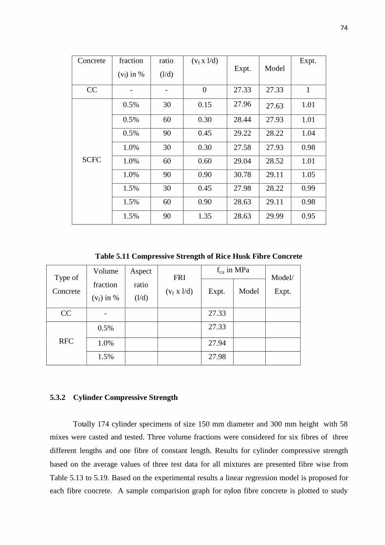
74
Concrete fraction
(vf) in %
ratio
(l/d)
(vf x l/d)Expt. Model
Expt.
CC - - 0 27.33 27.33 1
0.5% 30 0.15 27.96 27.63 1.01
0.5% 60 0.30 28.44 27.93 1.01
0.5% 90 0.45 29.22 28.22 1.04
1.0% 30 0.30 27.58 27.93 0.98
1.0% 60 0.60 29.04 28.52 1.01
1.0% 90 0.90 30.78 29.11 1.05
1.5% 30 0.45 27.98 28.22 0.99
1.5% 60 0.90 28.63 29.11 0.98
SCFC
1.5% 90 1.35 28.63 29.99 0.95
Table 5.11 Compressive Strength of Rice Husk Fibre Concrete
fcu in MPaType of
Concrete
Volume
fraction
(vf) in %
Aspect
ratio
(l/d)
FRI
(vf x l/d) Expt. Model
Model/
Expt.
CC - 27.33
0.5% 27.33
1.0% 27.94RFC
1.5% 27.98
5.3.2 Cylinder Compressive Strength
Totally 174 cylinder specimens of size 150 mm diameter and 300 mm height with 58
mixes were casted and tested. Three volume fractions were considered for six fibres of three
different lengths and one fibre of constant length. Results for cylinder compressive strength
based on the average values of three test data for all mixtures are presented fibre wise from
Table 5.13 to 5.19. Based on the experimental results a linear regression model is proposed for
each fibre concrete. A sample comparision graph for nylon fibre concrete is plotted to study
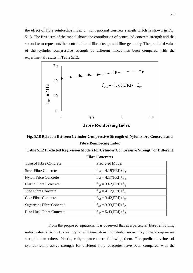
75
the effect of fibre reinforcing index on conventional concrete stength which is shown in Fig.
5.18. The first term of the model shows the contribution of controlled concrete strength and the
second term represents the contribution of fibre dosage and fibre geometry. The predicted value
of the cylinder compressive strength of different mixes has been compared with the
experimental results in Table 5.12.
Fig. 5.18 Relation Between Cylinder Compressive Strength of Nylon Fibre Concrete and
Fibre Reinforcing Index
Table 5.12 Predicted Regression Models for Cylinder Compressive Strength of Different
Fibre Concretes
Type of Fibre Concrete Predicted Model
Steel Fibre Concrete fcyf = 4.19(FRI)+fcy
Nylon Fibre Concrete fcyf = 4.17(FRI)+fcy
Plastic Fibre Concrete fcyf = 3.62(FRI)+fcy
Tyre Fibre Concrete fcyf = 4.17(FRI)+fcy
Coir Fibre Concrete fcyf = 3.42(FRI)+fcy
Sugarcane Fibre Concrete fcyf = 3.33(FRI)+fcy
Rice Husk Fibre Concrete fcyf = 5.43(FRI)+fcy
From the proposed equations, it is observed that at a particular fibre reinforcing
index value, rice husk, steel, nylon and tyre fibres contributed more in cylinder compressive
strength than others. Plastic, coir, sugarcene are following them. The predicted values of
cylinder compressive strength for different fibre concretes have been compared with the

76
experimental results. The comparision indicates that the proposed cylindervcompressive
strength model predicts the test data accurately. Table 5.14 also shows the percentage increase
in cylinder compressive strength of nylon fibre concrete over conventional concrete.
Table 5.13 Cylinder Compressive Strength of Steel Fibre Concrete
fcyf in MPaType of
Concrete
Volume
fraction
(vf) in %
Aspect
ratio
(l/d)
FRI
(vf x l/d) Expt. Model
Model/
Expt.
CC - - - 21.56 21.56 1.00
0.5% 30 0.15 23.12 22.19 0.96
0.5% 60 0.30 23.6 22.82 0.97
0.5% 90 0.45 24.02 23.45 0.98
1.0% 30 0.30 23.42 22.82 0.98
1.0% 60 0.60 24.34 24.08 0.99
1.0% 90 0.90 25.08 25.34 1.02
1.5% 30 0.45 24.34 23.45 0.97
1.5% 60 0.90 25.78 25.34 0.99
SFC
1.5% 90 1.35 26.04 27.22 1.05
Table 5.13 shows the cylinder compressive strength values of steel fibre concrete.
Table 5.14 Cylinder Compressive Strength of Nylon Fibre Concrete
fcyf in MPaType of
Concrete
Volume
fraction
(vf) in %
Aspect
ratio
(l/d)
FRI
(vf x l/d) Expt. Model
Model/
Expt.
CC - - 0 21.56 21.56 1
0.5% 30 0.15 22.42 22.19 0.99
0.5% 60 0.30 23.68 22.82 0.97
NFC
0.5% 90 0.45 24.12 23.44 0.98

77
1.0% 30 0.30 23.22 22.82 0.99
1.0% 60 0.60 24.14 24.07 1
1.0% 90 0.90 25.34 25.32 1
1.5% 30 0.45 24.06 23.44 0.98
1.5% 60 0.90 25.92 25.32 0.98
1.5% 90 1.35 25.98 27.19 1.05
Table 5.15 Cylinder Compressive Strength of Plastic Fibre Concrete
fcyf in MPaType of
Concrete
Volume
fraction
(vf) in %
Aspect
ratio
(l/d)
FRI
(vf x l/d) Expt. Model
Model/
Expt.
CC - - 0 21.56 21.56 1
0.5% 30 0.15 22.94 22.11 0.97
0.5% 60 0.30 23.68 22.65 0.96
0.5% 90 0.45 24.34 23.19 0.96
1.0% 30 0.30 23.84 22.65 0.96
1.0% 60 0.60 24.12 23.74 0.99
1.0% 90 0.90 25.01 24.82 1
1.5% 30 0.45 24.21 23.19 0.96
1.5% 60 0.90 24.42 24.82 1.02
PFC
1.5% 90 1.35 25.1 26.45 1.06
Table 5.16 Cylinder Compressive Strength of Tyre Fibre Concrete
fcyf in MPaType of
Concrete
Volume
fraction
(vf) in %
Aspect
ratio
(l/d)
FRI
(vf x l/d) Expt. Model
Model/
Expt.
CC - - 0 21.56 21.56 1
0.5% 30 0.15 22.22 22.19 1TFC
0.5% 60 0.30 23.43 22.82 0.98

78
0.5% 90 0.45 23.58 23.44 1
1.0% 30 0.30 22.01 22.82 1.04
1.0% 60 0.60 22.84 24.07 1.06
1.0% 90 0.90 24.85 25.32 1.02
1.5% 30 0.45 23.55 23.44 1
1.5% 60 0.90 23.56 25.32 1.08
1.5% 90 1.35 23.54 27.19 1.16
Table 5.17 Cylinder Compressive Strength of Coir Fibre Concrete
fcyf in MPaType of
Concrete
Volume
fraction
(vf) in %
Aspect
ratio
(l/d)
FRI
(vf x l/d) Expt. Model
Model/
Expt.
CC - - 0 21.56 21.56 1
0.5% 30 0.15 22.5 22.08 0.99
0.5% 60 0.30 23.02 22.59 0.99
0.5% 90 0.45 23.75 23.1 0.98
1.0% 30 0.30 23.08 22.59 0.98
1.0% 60 0.60 24.12 23.62 0.98
1.0% 90 0.90 24.67 24.64 1
1.5% 30 0.45 23.81 23.1 0.98
1.5% 60 0.90 24.64 24.64 1
CFC
1.5% 90 1.35 25.22 26.18 1.04
Table 5.18 Cylinder Compressive Strength of Sugarcane Fibre Concrete
fcyf in MPaType of
Concrete
Volume
fraction
(vf) in %
Aspect
ratio
(l/d)
FRI
(vf x l/d) Expt. Model
Model/
Expt.
CC - - 0 21.56 21.56 1
0.5% 30 0.15 23.89 22.06 0.93
0.5% 60 0.30 24.65 22.56 0.92
SCFC
0.5% 90 0.45 24.88 23.06 0.93
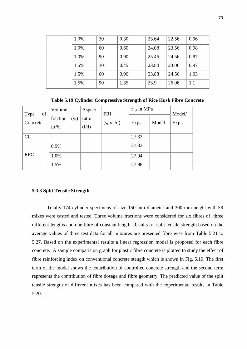
79
1.0% 30 0.30 23.64 22.56 0.96
1.0% 60 0.60 24.08 23.56 0.98
1.0% 90 0.90 25.46 24.56 0.97
1.5% 30 0.45 23.84 23.06 0.97
1.5% 60 0.90 23.88 24.56 1.03
1.5% 90 1.35 23.9 26.06 1.1
Table 5.19 Cylinder Compressive Strength of Rice Husk Fibre Concrete
fcyf in MPaType of
Concrete
Volume
fraction (vf)
in %
Aspect
ratio
(l/d)
FRI
(vf x l/d) Expt. Model
Model/
Expt.
CC - 27.33
0.5% 27.33
1.0% 27.94RFC
1.5% 27.98
5.3.3 Split Tensile Strength
Totally 174 cylinder specimens of size 150 mm diameter and 300 mm height with 58
mixes were casted and tested. Three volume fractions were considered for six fibres of three
different lengths and one fibre of constant length. Results for split tensile strength based on the
average values of three test data for all mixtures are presented fibre wise from Table 5.21 to
5.27. Based on the experimental results a linear regression model is proposed for each fibre
concrete. A sample comparision graph for plastic fibre concrete is plotted to study the effect of
fibre reinforcing index on conventional concrete stength which is shown in Fig. 5.19. The first
term of the model shows the contribution of controlled concrete strength and the second term
represents the contribution of fibre dosage and fibre geometry. The predicted value of the split
tensile strength of different mixes has been compared with the experimental results in Table
5.20.

80
Fig. 5.19 Relation Between split tensile Strength of Plastic Fibre Concrete and Fibre
Reinforcing Index
Table 5.20 Predicted Regression Models for split tensile Strength of Different Fibre
Concretes
Type of Fibre Concrete Predicted Model
Steel Fibre Concrete fcyf = 1.68(FRI)+fcy
Nylon Fibre Concrete fcyf = 1.03(FRI)+fcy
Plastic Fibre Concrete fcyf = 1.04(FRI)+fcy
Tyre Fibre Concrete fcyf = 0.72(FRI)+fcy
Coir Fibre Concrete fcyf = 0.83(FRI)+fcy
Sugarcane Fibre Concrete fcyf = 0.71(FRI)+fcy
Rice Husk Fibre Concrete fcyf = 0.26(FRI)+fcy
From the proposed equations, it is observed that at a particular fibre reinforcing
index value, rice husk, steel, nylon and tyre fibres contributed more in cylinder compressive
strength than others. Plastic, coir, sugarcene are following them. The predicted values of
cylinder compressive strength for different fibre concretes have been compared with the
experimental results. The comparision indicates that the proposed cylinder compressive
strength model predicts the test data accurately. Table 5.14 also shows the percentage increase
in cylinder compressive strength of nylon fibre concrete over conventional concrete.
Table 5.21 Split Tensile Strength of Steel Fibre Concrete

81
fspf in MPaType of
Concrete
Volume
fraction
(vf) in %
Aspect
ratio
(l/d)
FRI
(vf x l/d) Expt. Model
Model/
Expt.
CC - - - 2.86 2.86 1
0.5% 30 0.15 3.22 3.12 0.97
0.5% 60 0.30 3.56 3.37 0.95
0.5% 90 0.45 3.75 3.62 0.97
1.0% 30 0.30 3.53 3.37 0.96
1.0% 60 0.60 3.92 3.87 0.99
1.0% 90 0.90 4.42 4.38 1
1.5% 30 0.45 3.81 3.62 0.96
1.5% 60 0.90 4.28 4.38 1.03
SFC
1.5% 90 1.35 4.92 5.13 1.05
Table 5.13 shows the cylinder compressive strength values of steel fibre concrete.
Table 5.22 Split Tensile Strength of Nylon Fibre Concrete
fspf in MPaType of
Concrete
Volume
fraction
(vf) in %
Aspect
ratio
(l/d)
FRI
(vf x l/d) Expt. Model
Model/
Expt.
CC - - 0 2.86 2.86 1
0.5% 30 0.15 3.12 3.02 0.97
0.5% 60 0.30 3.45 3.17 0.92
0.5% 90 0.45 3.58 3.33 0.94
1.0% 30 0.30 3.22 3.17 0.99
1.0% 60 0.60 3.48 3.48 1
1.0% 90 0.90 3.78 3.79 1.01
1.5% 30 0.45 3.46 3.33 0.97
NFC
1.5% 60 0.90 3.92 3.79 0.97

82
1.5% 90 1.35 3.94 4.26 1.09
Table 5.23 Split Tensile Strength of Plastic Fibre Concrete
fspf in MPaType of
Concrete
Volume
fraction
(vf) in %
Aspect
ratio
(l/d)
FRI
(vf x l/d) Expt. Model
Model/
Expt.
CC - - 0 2.86 2.86 1
0.5% 30 0.15 2.98 3.02 1.02
0.5% 60 0.30 3.45 3.18 0.93
0.5% 90 0.45 3.86 3.33 0.87
1.0% 30 0.30 3.12 3.18 1.02
1.0% 60 0.60 3.49 3.49 1
1.0% 90 0.90 3.99 3.8 0.96
1.5% 30 0.45 3.21 3.33 1.04
1.5% 60 0.90 3.67 3.8 1.04
PFC
1.5% 90 1.35 4.02 4.27 1.07
Table 5.24 Split Tensile Strength of Tyre Fibre Concrete
fspf in MPaType of
Concrete
Volume
fraction
(vf) in %
Aspect
ratio
(l/d)
FRI
(vf x l/d) Expt. Model
Model/
Expt.
CC - - 0 2.86 2.86 1
0.5% 30 0.15 2.85 2.97 1.05
0.5% 60 0.30 3.74 3.08 0.83
0.5% 90 0.45 3.95 3.19 0.81
TFC
1.0% 30 0.30 2.67 3.08 1.16

83
1.0% 60 0.60 3.56 3.3 0.93
1.0% 90 0.90 3.85 3.51 0.92
1.5% 30 0.45 3.48 3.19 0.92
1.5% 60 0.90 3.24 3.51 1.09
1.5% 90 1.35 3.28 3.84 1.18
Table 5.25 Split Tensile Strength of Coir Fibre Concrete
fspf in MPaType of
Concrete
Volume
fraction
(vf) in %
Aspect
ratio
(l/d)
FRI
(vf x l/d) Expt. Model
Model/
Expt.
CC - - 0 2.86 2.86 1
0.5% 30 0.15 2.98 2.99 1.01
0.5% 60 0.30 3.06 3.11 1.02
0.5% 90 0.45 3.12 3.24 1.04
1.0% 30 0.30 3.24 3.11 0.96
1.0% 60 0.60 3.92 3.36 0.86
1.0% 90 0.90 3.98 3.61 0.91
1.5% 30 0.45 3.22 3.24 1.01
1.5% 60 0.90 3.64 3.61 1
CFC
1.5% 90 1.35 3.48 3.99 1.15
Table 5.26 Split Tensile Strength of Sugarcane Fibre Concrete
fspf in MPaType of
Concrete
Volume
fraction
(vf) in %
Aspect
ratio
(l/d)
FRI
(vf x l/d) Expt. Model
Model/
Expt.
CC - - 0 2.86 2.86 1
0.5% 30 0.15 2.86 2.97 1.04
0.5% 60 0.30 2.86 3.08 1.08
SCFC
0.5% 90 0.45 3.14 3.18 1.02
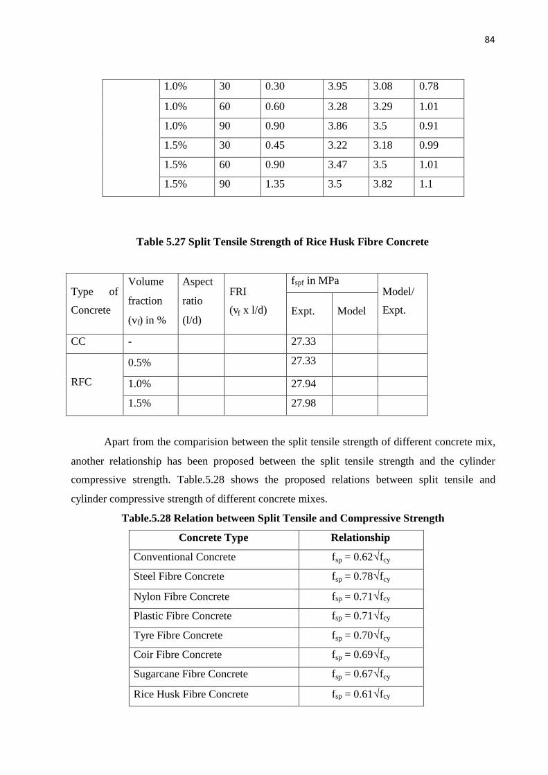
84
1.0% 30 0.30 3.95 3.08 0.78
1.0% 60 0.60 3.28 3.29 1.01
1.0% 90 0.90 3.86 3.5 0.91
1.5% 30 0.45 3.22 3.18 0.99
1.5% 60 0.90 3.47 3.5 1.01
1.5% 90 1.35 3.5 3.82 1.1
Table 5.27 Split Tensile Strength of Rice Husk Fibre Concrete
fspf in MPaType of
Concrete
Volume
fraction
(vf) in %
Aspect
ratio
(l/d)
FRI
(vf x l/d) Expt. Model
Model/
Expt.
CC - 27.33
0.5% 27.33
1.0% 27.94RFC
1.5% 27.98
Apart from the comparision between the split tensile strength of different concrete mix,
another relationship has been proposed between the split tensile strength and the cylinder
compressive strength. Table.5.28 shows the proposed relations between split tensile and
cylinder compressive strength of different concrete mixes.
Table.5.28 Relation between Split Tensile and Compressive Strength
Concrete Type Relationship
Conventional Concrete fsp = 0.62√fcy
Steel Fibre Concrete fsp = 0.78√fcy
Nylon Fibre Concrete fsp = 0.71√fcy
Plastic Fibre Concrete fsp = 0.71√fcy
Tyre Fibre Concrete fsp = 0.70√fcy
Coir Fibre Concrete fsp = 0.69√fcy
Sugarcane Fibre Concrete fsp = 0.67√fcy
Rice Husk Fibre Concrete fsp = 0.61√fcy
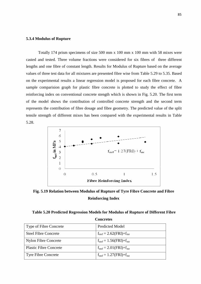
85
5.3.4 Modulus of Rupture
Totally 174 prism specimens of size 500 mm x 100 mm x 100 mm with 58 mixes were
casted and tested. Three volume fractions were considered for six fibres of three different
lengths and one fibre of constant length. Results for Modulus of Rupture based on the average
values of three test data for all mixtures are presented fibre wise from Table 5.29 to 5.35. Based
on the experimental results a linear regression model is proposed for each fibre concrete. A
sample comparision graph for plastic fibre concrete is plotted to study the effect of fibre
reinforcing index on conventional concrete stength which is shown in Fig. 5.20. The first term
of the model shows the contribution of controlled concrete strength and the second term
represents the contribution of fibre dosage and fibre geometry. The predicted value of the split
tensile strength of different mixes has been compared with the experimental results in Table
5.28.
Fig. 5.19 Relation between Modulus of Rupture of Tyre Fibre Concrete and Fibre
Reinforcing Index
Table 5.20 Predicted Regression Models for Modulus of Rupture of Different Fibre
Concretes
Type of Fibre Concrete Predicted Model
Steel Fibre Concrete fmrf = 2.62(FRI)+fmr
Nylon Fibre Concrete fmrf = 1.56(FRI)+fmr
Plastic Fibre Concrete fmrf = 2.01(FRI)+fmr
Tyre Fibre Concrete fmrf = 1.27(FRI)+fmr
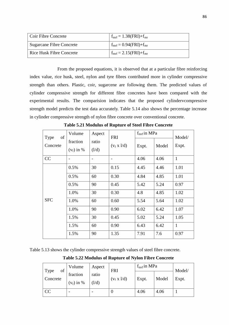
86
Coir Fibre Concrete fmrf = 1.38(FRI)+fmr
Sugarcane Fibre Concrete fmrf = 0.94(FRI)+fmr
Rice Husk Fibre Concrete fmrf = 2.15(FRI)+fmr
From the proposed equations, it is observed that at a particular fibre reinforcing
index value, rice husk, steel, nylon and tyre fibres contributed more in cylinder compressive
strength than others. Plastic, coir, sugarcene are following them. The predicted values of
cylinder compressive strength for different fibre concretes have been compared with the
experimental results. The comparision indicates that the proposed cylindervcompressive
strength model predicts the test data accurately. Table 5.14 also shows the percentage increase
in cylinder compressive strength of nylon fibre concrete over conventional concrete.
Table 5.21 Modulus of Rupture of Steel Fibre Concrete
fmrf in MPaType of
Concrete
Volume
fraction
(vf) in %
Aspect
ratio
(l/d)
FRI
(vf x l/d) Expt. Model
Model/
Expt.
CC - - - 4.06 4.06 1
0.5% 30 0.15 4.45 4.46 1.01
0.5% 60 0.30 4.84 4.85 1.01
0.5% 90 0.45 5.42 5.24 0.97
1.0% 30 0.30 4.8 4.85 1.02
1.0% 60 0.60 5.54 5.64 1.02
1.0% 90 0.90 6.02 6.42 1.07
1.5% 30 0.45 5.02 5.24 1.05
1.5% 60 0.90 6.43 6.42 1
SFC
1.5% 90 1.35 7.91 7.6 0.97
Table 5.13 shows the cylinder compressive strength values of steel fibre concrete.
Table 5.22 Modulus of Rupture of Nylon Fibre Concrete
fmrf in MPaType of
Concrete
Volume
fraction
(vf) in %
Aspect
ratio
(l/d)
FRI
(vf x l/d) Expt. Model
Model/
Expt.
CC - - 0 4.06 4.06 1

87
0.5% 30 0.15 4.22 4.3 1.02
0.5% 60 0.30 4.86 4.53 0.94
0.5% 90 0.45 5.23 4.77 0.92
1.0% 30 0.30 4.34 4.53 1.05
1.0% 60 0.60 4.97 5 1.01
1.0% 90 0.90 5.34 5.47 1.03
1.5% 30 0.45 4.56 4.77 1.05
1.5% 60 0.90 5.34 5.47 1.03
NFC
1.5% 90 1.35 6.23 6.17 1
Table 5.23 Modulus of Rupture of Plastic Fibre Concrete
fmrf in MPaType of
Concrete
Volume
fraction
(vf) in %
Aspect
ratio
(l/d)
FRI
(vf x l/d) Expt. Model
Model/
Expt.
CC - - 0 4.06 4.06 1
0.5% 30 0.15 4.23 4.35 1.03
0.5% 60 0.30 4.98 4.63 0.93
0.5% 90 0.45 5.68 4.91 0.87
1.0% 30 0.30 5.34 4.63 0.87
1.0% 60 0.60 5.96 5.19 0.88
1.0% 90 0.90 6 5.75 0.96
1.5% 30 0.45 4.67 4.91 1.06
1.5% 60 0.90 5.84 5.75 0.99
PFC
1.5% 90 1.35 6.05 6.59 1.09
Table 5.24 Modulus of Rupture of Tyre Fibre Concrete
fmrf in MPaType of
Concrete
Volume
fraction
(vf) in %
Aspect
ratio
(l/d)
FRI
(vf x l/d) Expt. Model
Model/
Expt.
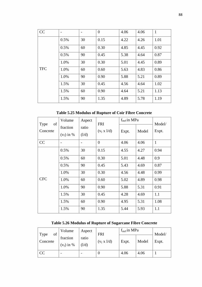
88
CC - - 0 4.06 4.06 1
0.5% 30 0.15 4.22 4.26 1.01
0.5% 60 0.30 4.85 4.45 0.92
0.5% 90 0.45 5.38 4.64 0.87
1.0% 30 0.30 5.01 4.45 0.89
1.0% 60 0.60 5.63 4.83 0.86
1.0% 90 0.90 5.88 5.21 0.89
1.5% 30 0.45 4.56 4.64 1.02
1.5% 60 0.90 4.64 5.21 1.13
TFC
1.5% 90 1.35 4.89 5.78 1.19
Table 5.25 Modulus of Rupture of Coir Fibre Concrete
fmrf in MPaType of
Concrete
Volume
fraction
(vf) in %
Aspect
ratio
(l/d)
FRI
(vf x l/d) Expt. Model
Model/
Expt.
CC - - 0 4.06 4.06 1
0.5% 30 0.15 4.55 4.27 0.94
0.5% 60 0.30 5.01 4.48 0.9
0.5% 90 0.45 5.43 4.69 0.87
1.0% 30 0.30 4.56 4.48 0.99
1.0% 60 0.60 5.02 4.89 0.98
1.0% 90 0.90 5.88 5.31 0.91
1.5% 30 0.45 4.28 4.69 1.1
1.5% 60 0.90 4.95 5.31 1.08
CFC
1.5% 90 1.35 5.44 5.93 1.1
Table 5.26 Modulus of Rupture of Sugarcane Fibre Concrete
fmrf in MPaType of
Concrete
Volume
fraction
(vf) in %
Aspect
ratio
(l/d)
FRI
(vf x l/d) Expt. Model
Model/
Expt.
CC - - 0 4.06 4.06 1
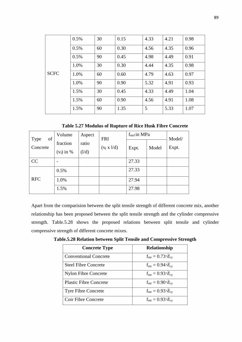
89
0.5% 30 0.15 4.33 4.21 0.98
0.5% 60 0.30 4.56 4.35 0.96
0.5% 90 0.45 4.98 4.49 0.91
1.0% 30 0.30 4.44 4.35 0.98
1.0% 60 0.60 4.79 4.63 0.97
1.0% 90 0.90 5.32 4.91 0.93
1.5% 30 0.45 4.33 4.49 1.04
1.5% 60 0.90 4.56 4.91 1.08
SCFC
1.5% 90 1.35 5 5.33 1.07
Table 5.27 Modulus of Rupture of Rice Husk Fibre Concrete
fmrf in MPaType of
Concrete
Volume
fraction
(vf) in %
Aspect
ratio
(l/d)
FRI
(vf x l/d) Expt. Model
Model/
Expt.
CC - 27.33
0.5% 27.33
1.0% 27.94RFC
1.5% 27.98
Apart from the comparision between the split tensile strength of different concrete mix, another
relationship has been proposed between the split tensile strength and the cylinder compressive
strength. Table.5.28 shows the proposed relations between split tensile and cylinder
compressive strength of different concrete mixes.
Table.5.28 Relation between Split Tensile and Compressive Strength
Concrete Type Relationship
Conventional Concrete fmr = 0.73√fcy
Steel Fibre Concrete fmr = 0.94√fcy
Nylon Fibre Concrete fmr = 0.93√fcy
Plastic Fibre Concrete fmr = 0.90√fcy
Tyre Fibre Concrete fmr = 0.93√fcy
Coir Fibre Concrete fmr = 0.93√fcy
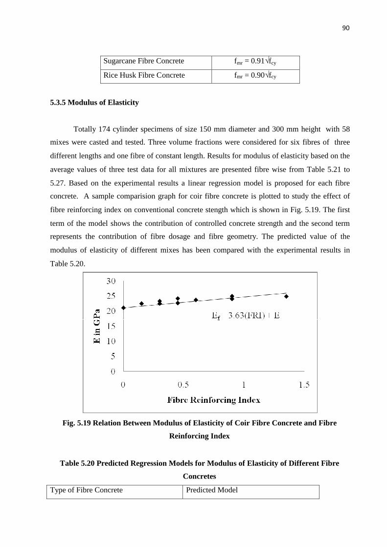
90
Sugarcane Fibre Concrete fmr = 0.91√fcy
Rice Husk Fibre Concrete fmr = 0.90√fcy
5.3.5 Modulus of Elasticity
Totally 174 cylinder specimens of size 150 mm diameter and 300 mm height with 58
mixes were casted and tested. Three volume fractions were considered for six fibres of three
different lengths and one fibre of constant length. Results for modulus of elasticity based on the
average values of three test data for all mixtures are presented fibre wise from Table 5.21 to
5.27. Based on the experimental results a linear regression model is proposed for each fibre
concrete. A sample comparision graph for coir fibre concrete is plotted to study the effect of
fibre reinforcing index on conventional concrete stength which is shown in Fig. 5.19. The first
term of the model shows the contribution of controlled concrete strength and the second term
represents the contribution of fibre dosage and fibre geometry. The predicted value of the
modulus of elasticity of different mixes has been compared with the experimental results in
Table 5.20.
Fig. 5.19 Relation Between Modulus of Elasticity of Coir Fibre Concrete and Fibre
Reinforcing Index
Table 5.20 Predicted Regression Models for Modulus of Elasticity of Different Fibre
Concretes
Type of Fibre Concrete Predicted Model

91
Steel Fibre Concrete Ef = 7.18(FRI)+E
Nylon Fibre Concrete Ef = 5.55(FRI)+E
Plastic Fibre Concrete Ef = 4.43(FRI)+E
Tyre Fibre Concrete Ef = 5.82(FRI)+E
Coir Fibre Concrete Ef = 3.63(FRI)+E
Sugarcane Fibre Concrete Ef = 3.10(FRI)+E
Rice Husk Fibre Concrete Ef = 5.62(FRI)+E
From the proposed equations, it is observed that at a particular fibre reinforcing
index value, rice husk, steel, nylon and tyre fibres contributed more in cylinder compressive
strength than others. Plastic, coir, sugarcene are following them. The predicted values of
cylinder compressive strength for different fibre concretes have been compared with the
experimental results. The comparision indicates that the proposed cylindervcompressive
strength model predicts the test data accurately. Table 5.14 also shows the percentage increase
in cylinder compressive strength of nylon fibre concrete over conventional concrete.
Table 5.21 Modulus of Elasticity of Steel Fibre Concrete
Ef in MPaType of
Concrete
Volume
fraction
(vf) in %
Aspect
ratio
(l/d)
FRI
(vf x l/d) Expt. Model
Model/
Expt.
CC - - - 21.06 21.06 1
0.5% 30 0.15 24.57 22.14 0.91
0.5% 60 0.30 25.18 23.22 0.93
0.5% 90 0.45 25.87 24.30 0.94
1.0% 30 0.30 24.49 23.22 0.95
1.0% 60 0.60 26.90 25.37 0.95
1.0% 90 0.90 27.29 27.53 1.01
1.5% 30 0.45 25.56 24.30 0.96
1.5% 60 0.90 27.32 27.53 1.01
SFC
1.5% 90 1.35 28.40 30.76 1.09
Table 5.13 shows the cylinder compressive strength values of steel fibre concrete.

92
Table 5.22 Modulus of Elasticity of Nylon Fibre Concrete
Ef in MPaType of
Concrete
Volume
fraction
(vf) in %
Aspect
ratio
(l/d)
FRI
(vf x l/d) Expt. Model
Model/
Expt.
CC - - 0 21.06 21.06 1
0.5% 30 0.15 23.45 21.90 0.94
0.5% 60 0.30 24.90 22.73 0.92
0.5% 90 0.45 25.57 23.56 0.93
1.0% 30 0.30 24.00 22.73 0.95
1.0% 60 0.60 25.48 24.39 0.96
1.0% 90 0.90 26.20 26.06 1
1.5% 30 0.45 24.58 23.56 0.96
1.5% 60 0.90 25.48 26.06 1.03
NFC
1.5% 90 1.35 26.39 28.56 1.09
Table 5.23 Modulus of Elasticity of Plastic Fibre Concrete
Ef in MPaType of
Concrete
Volume
fraction
(vf) in %
Aspect
ratio
(l/d)
FRI
(vf x l/d) Expt. Model
Model/
Expt.
CC - - 0 21.06 21.06 1
0.5% 30 0.15 23.45 21.73 0.93
0.5% 60 0.30 24.56 22.39 0.92
0.5% 90 0.45 24.83 23.06 0.93
1.0% 30 0.30 23.23 22.39 0.97
1.0% 60 0.60 24.35 23.72 0.98
1.0% 90 0.90 24.56 25.05 1.02
1.5% 30 0.45 23.94 23.06 0.97
1.5% 60 0.90 24.35 25.05 1.03
PFC
1.5% 90 1.35 25.78 27.05 1.05
Table 5.24 Modulus of Elasticity of Tyre Fibre Concrete

93
Ef in MPaType of
Concrete
Volume
fraction
(vf) in %
Aspect
ratio
(l/d)
FRI
(vf x l/d) Expt. Model
Model/
Expt.
CC - - 0 21.059 21.059 1
0.5% 30 0.15 22.4 21.939 0.98
0.5% 60 0.30 23.12 22.809 0.99
0.5% 90 0.45 24.452 23.679 0.97
1.0% 30 0.30 23.462 22.809 0.98
1.0% 60 0.60 25.689 24.559 0.96
1.0% 90 0.90 26.064 26.299 1.01
1.5% 30 0.45 25.4 23.679 0.94
1.5% 60 0.90 26.48 26.299 1
TFC
1.5% 90 1.35 27.345 28.919 1.06
Table 5.25 Modulus of Elasticity of Coir Fibre Concrete
Ef in MPaType of
Concrete
Volume
fraction
(vf) in %
Aspect
ratio
(l/d)
FRI
(vf x l/d) Expt. Model
Model/
Expt.
CC - - 0 21.06 21.06 1
0.5% 30 0.15 22.45 21.61 0.97
0.5% 60 0.30 23.26 22.15 0.96
0.5% 90 0.45 24.12 22.70 0.95
1.0% 30 0.30 22.45 22.15 0.99
1.0% 60 0.60 23.64 23.24 0.99
1.0% 90 0.90 24.88 24.33 0.98
1.5% 30 0.45 22.63 22.70 1.01
1.5% 60 0.90 23.97 24.33 1.02
CFC
1.5% 90 1.35 24.79 25.97 1.05
Table 5.26 Modulus of Elasticity of Sugarcane Fibre Concrete

94
Ef in MPaType of
Concrete
Volume
fraction
(vf) in %
Aspect
ratio
(l/d)
FRI
(vf x l/d) Expt. Model
Model/
Expt.
CC - - 0 21.06 21.06 1
0.5% 30 0.15 22.00 21.53 0.98
0.5% 60 0.30 23.34 21.99 0.95
0.5% 90 0.45 24.12 22.46 0.94
1.0% 30 0.30 22.39 21.99 0.99
1.0% 60 0.60 23.06 22.92 1
1.0% 90 0.90 24.79 23.85 0.97
1.5% 30 0.45 22.99 22.46 0.98
1.5% 60 0.90 23.14 23.85 1.04
SCFC
1.5% 90 1.35 23.87 25.25 1.06
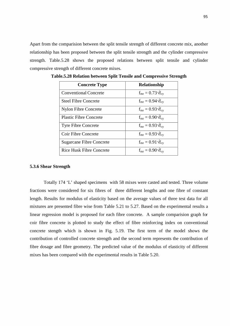
95
Apart from the comparision between the split tensile strength of different concrete mix, another
relationship has been proposed between the split tensile strength and the cylinder compressive
strength. Table.5.28 shows the proposed relations between split tensile and cylinder
compressive strength of different concrete mixes.
Table.5.28 Relation between Split Tensile and Compressive Strength
Concrete Type Relationship
Conventional Concrete fmr = 0.73√fcy
Steel Fibre Concrete fmr = 0.94√fcy
Nylon Fibre Concrete fmr = 0.93√fcy
Plastic Fibre Concrete fmr = 0.90√fcy
Tyre Fibre Concrete fmr = 0.93√fcy
Coir Fibre Concrete fmr = 0.93√fcy
Sugarcane Fibre Concrete fmr = 0.91√fcy
Rice Husk Fibre Concrete fmr = 0.90√fcy
5.3.6 Shear Strength
Totally 174 ‘L’ shaped specimens with 58 mixes were casted and tested. Three volume
fractions were considered for six fibres of three different lengths and one fibre of constant
length. Results for modulus of elasticity based on the average values of three test data for all
mixtures are presented fibre wise from Table 5.21 to 5.27. Based on the experimental results a
linear regression model is proposed for each fibre concrete. A sample comparision graph for
coir fibre concrete is plotted to study the effect of fibre reinforcing index on conventional
concrete stength which is shown in Fig. 5.19. The first term of the model shows the
contribution of controlled concrete strength and the second term represents the contribution of
fibre dosage and fibre geometry. The predicted value of the modulus of elasticity of different
mixes has been compared with the experimental results in Table 5.20.

96
Fig. 5.19 Relation between Cracking shear strength of Sugarcane Fibre Concrete and
Fibre Reinforcing Index
Table 5.20 Predicted Regression Models for Modulus of Elasticity of Different Fibre
Concretes
Type of Fibre Concrete Predicted Model
Steel Fibre Concrete fssf= 1.73(FRI)+fss
Nylon Fibre Concrete fssf= 1.85(FRI)+fss
Plastic Fibre Concrete fssf= 2.06(FRI)+fss
Tyre Fibre Concrete fssf= 1.49(FRI)+fss
Coir Fibre Concrete fssf= 1.08(FRI)+fss
Sugarcane Fibre Concrete fssf= 0.86(FRI)+fss
Rice Husk Fibre Concrete fssf= 0.95(FRI)+fss
From the proposed equations, it is observed that at a particular fibre reinforcing index
value, rice husk, steel, nylon and tyre fibres contributed more in cylinder compressive strength
than others. Plastic, coir, sugarcene are following them. The predicted values of cylinder
compressive strength for different fibre concretes have been compared with the experimental
results. The comparision indicates that the proposed cylindervcompressive strength model
predicts the test data accurately. Table 5.14 also shows the percentage increase in cylinder
compressive strength of nylon fibre concrete over conventional concrete.
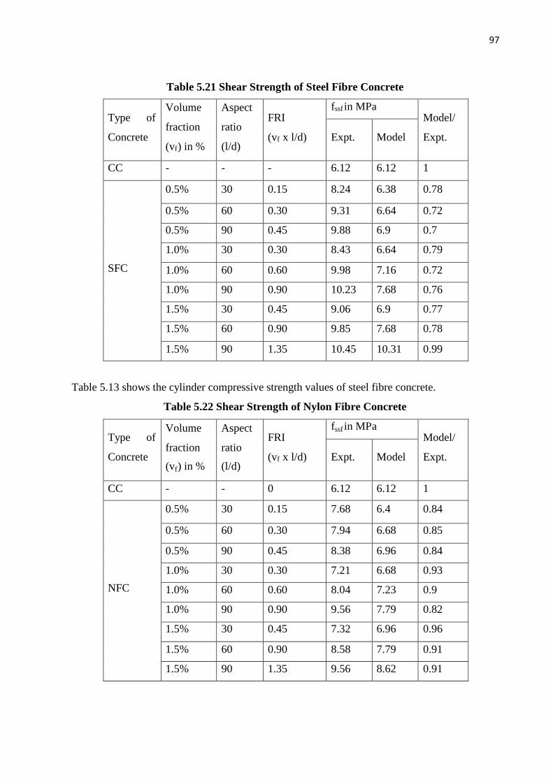
97
Table 5.21 Shear Strength of Steel Fibre Concrete
fssf in MPaType of
Concrete
Volume
fraction
(vf) in %
Aspect
ratio
(l/d)
FRI
(vf x l/d) Expt. Model
Model/
Expt.
CC - - - 6.12 6.12 1
0.5% 30 0.15 8.24 6.38 0.78
0.5% 60 0.30 9.31 6.64 0.72
0.5% 90 0.45 9.88 6.9 0.7
1.0% 30 0.30 8.43 6.64 0.79
1.0% 60 0.60 9.98 7.16 0.72
1.0% 90 0.90 10.23 7.68 0.76
1.5% 30 0.45 9.06 6.9 0.77
1.5% 60 0.90 9.85 7.68 0.78
SFC
1.5% 90 1.35 10.45 10.31 0.99
Table 5.13 shows the cylinder compressive strength values of steel fibre concrete.
Table 5.22 Shear Strength of Nylon Fibre Concrete
fssf in MPaType of
Concrete
Volume
fraction
(vf) in %
Aspect
ratio
(l/d)
FRI
(vf x l/d) Expt. Model
Model/
Expt.
CC - - 0 6.12 6.12 1
0.5% 30 0.15 7.68 6.4 0.84
0.5% 60 0.30 7.94 6.68 0.85
0.5% 90 0.45 8.38 6.96 0.84
1.0% 30 0.30 7.21 6.68 0.93
1.0% 60 0.60 8.04 7.23 0.9
1.0% 90 0.90 9.56 7.79 0.82
1.5% 30 0.45 7.32 6.96 0.96
1.5% 60 0.90 8.58 7.79 0.91
NFC
1.5% 90 1.35 9.56 8.62 0.91

98
Table 5.23 Shear Strength of Plastic Fibre Concrete
fssf in MPaType of
Concrete
Volume
fraction
(vf) in %
Aspect
ratio
(l/d)
FRI
(vf x l/d) Expt. Model
Model/
Expt.
CC - - 0 6.12 6.12 1
0.5% 30 0.15 6.78 6.43 0.95
0.5% 60 0.30 7.72 6.74 0.88
0.5% 90 0.45 8.06 7.05 0.88
1.0% 30 0.30 6.89 6.74 0.98
1.0% 60 0.60 7.46 7.36 0.99
1.0% 90 0.90 8.35 7.98 0.96
1.5% 30 0.45 6.77 7.05 1.05
1.5% 60 0.90 7.92 7.98 1.01
PFC
1.5% 90 1.35 8.02 8.91 1.12
Table 5.24 Shear Strength of Tyre Fibre Concrete
fssf in MPaType of
Concrete
Volume
fraction
(vf) in %
Aspect
ratio
(l/d)
FRI
(vf x l/d) Expt. Model
Model/
Expt.
CC - - 0 6.12 6.12 1
0.5% 30 0.15 6.56 6.35 0.97
0.5% 60 0.30 7 6.57 0.94
0.5% 90 0.45 7.21 6.8 0.95
1.0% 30 0.30 6.89 6.57 0.96
1.0% 60 0.60 6.95 7.02 1.02
1.0% 90 0.90 7.34 7.47 1.02
1.5% 30 0.45 6.98 6.8 0.98
1.5% 60 0.90 7.01 7.47 1.07
TFC
1.5% 90 1.35 6.89 8.14 1.19
Table 5.25 Compressive Shear Strength of Coir Fibre Concrete
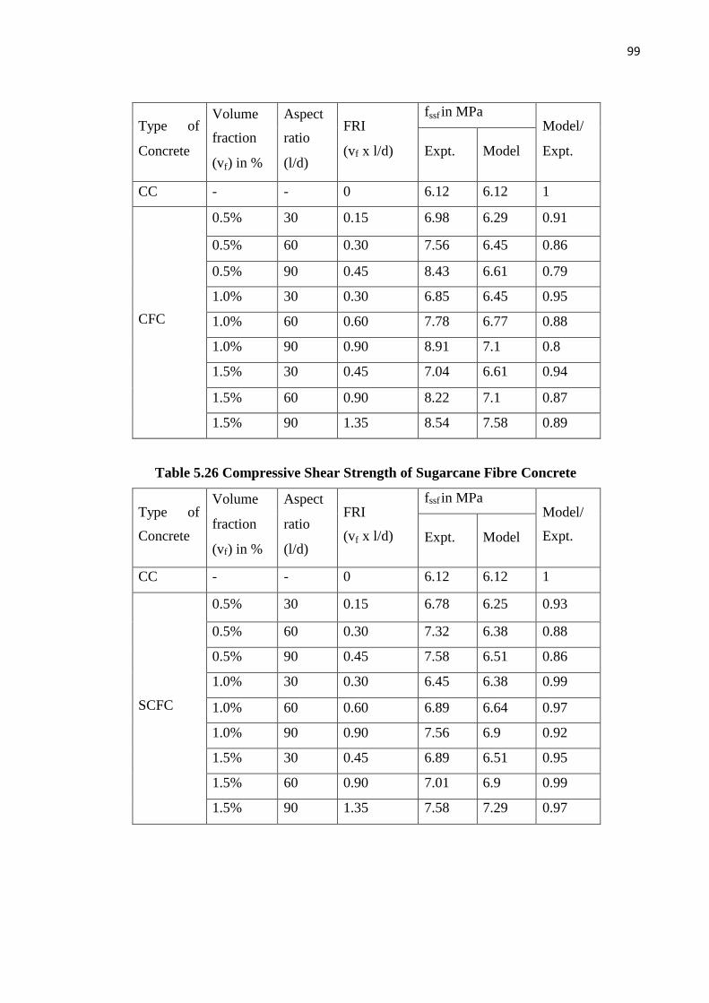
99
fssf in MPaType of
Concrete
Volume
fraction
(vf) in %
Aspect
ratio
(l/d)
FRI
(vf x l/d) Expt. Model
Model/
Expt.
CC - - 0 6.12 6.12 1
0.5% 30 0.15 6.98 6.29 0.91
0.5% 60 0.30 7.56 6.45 0.86
0.5% 90 0.45 8.43 6.61 0.79
1.0% 30 0.30 6.85 6.45 0.95
1.0% 60 0.60 7.78 6.77 0.88
1.0% 90 0.90 8.91 7.1 0.8
1.5% 30 0.45 7.04 6.61 0.94
1.5% 60 0.90 8.22 7.1 0.87
CFC
1.5% 90 1.35 8.54 7.58 0.89
Table 5.26 Compressive Shear Strength of Sugarcane Fibre Concrete
fssf in MPaType of
Concrete
Volume
fraction
(vf) in %
Aspect
ratio
(l/d)
FRI
(vf x l/d) Expt. Model
Model/
Expt.
CC - - 0 6.12 6.12 1
0.5% 30 0.15 6.78 6.25 0.93
0.5% 60 0.30 7.32 6.38 0.88
0.5% 90 0.45 7.58 6.51 0.86
1.0% 30 0.30 6.45 6.38 0.99
1.0% 60 0.60 6.89 6.64 0.97
1.0% 90 0.90 7.56 6.9 0.92
1.5% 30 0.45 6.89 6.51 0.95
1.5% 60 0.90 7.01 6.9 0.99
SCFC
1.5% 90 1.35 7.58 7.29 0.97

100
Apart from the comparision between the split tensile strength of different concrete mix,
another relationship has been proposed between the split tensile strength and the cylinder
compressive strength. Table.5.28 shows the proposed relations between split tensile and
cylinder compressive strength of different concrete mixes.
Table.5.28 Relation between Split Tensile and Compressive Strength
Concrete Type Relationship
Conventional Concrete fmr = 0.73√fcy
Steel Fibre Concrete fmr = 0.94√fcy
Nylon Fibre Concrete fmr = 0.93√fcy
Plastic Fibre Concrete fmr = 0.90√fcy
Tyre Fibre Concrete fmr = 0.93√fcy
Coir Fibre Concrete fmr = 0.93√fcy
Sugarcane Fibre Concrete fmr = 0.91√fcy
Rice Husk Fibre Concrete fmr = 0.90√fcy
![IS 11060 (1984): Rubberized Coir Cushioning - ccriindia.org is.11060.1984.pdf · IS 11060 (1984): Rubberized Coir Cushioning [TXD 25: Coir and Coir Products] iS:liO60 :1984 MOULDED](https://img.pdfslide.us/doc/110x75/5b5bf1b67f8b9a2d458ea426/is-11060-1984-rubberized-coir-cushioning-is110601984pdf-is-11060-1984.jpg)
![Coir Fibre Reinforcement and Application in Polymer ... · Coir Fibre Reinforcement and Application in Polymer Composites: A Review D. Verma1*, ... Matrices [5] materials in composites](https://img.pdfslide.us/doc/110x75/5e3d60412c5aab7cd60ded2f/coir-fibre-reinforcement-and-application-in-polymer-coir-fibre-reinforcement.jpg)


![COIR PITH - Krishna districtkrishna.nic.in/PDFfiles/MSME/Chemical/coir pith[1].pdfMushroom Coir pith blocks are being used by a lot of mushroom growers around the ... Coir dust in](https://img.pdfslide.us/doc/110x75/5aa91e107f8b9a9a188c6a23/coir-pith-krishna-pith1pdfmushroom-coir-pith-blocks-are-being-used-by-a-lot.jpg)


![Advanced Materials Manufacturing & Characterization · 2017-09-28 · [8-12]. The tensile properties of sisal, hemp, coir, kenaf, and jute reinforced composites have been studied](https://img.pdfslide.us/doc/110x75/5f6d50e3c0ed2e008c6979aa/advanced-materials-manufacturing-2017-09-28-8-12-the-tensile-properties.jpg)