Embed Size (px)
Citation preview
98 ECTI TRANSACTIONS ON ELECTRICAL ENG., ELECTRONICS, AND COMMUNICATIONS VOL.10, NO.1 February 2012
Application of Artificial Bees ColonyAlgorithm for Optimal Overcurrent Relay
Coordination Problems
Dusit Uthitsunthorn1 ,
Padej Pao-la-or2 , and Thanatchai Kulworawanichpong3 , Non-members
ABSTRACT
This paper presents optimal coordination of over-current relays by using artificial bees colony algo-rithm. The objective function of the relay coordi-nation problem is to minimize the operation time ofassociated relays in the systems. The control vari-ables used in this paper are the pickup current andtime dial setting of relays. The proposed method wastested with four systems study consists 5-bus, 6-bus,9-bus and 14-bus. Quasi-Newton (BFGS), particleswarm optimization (PSO) and artificial bees colony(ABC) are employed to evaluate the search perfor-mance. For test, there are study test power systemwas used. The simulation results showed that the ar-tificial bees colony algorithm is capable to minimizethe operation time of relays in the entire system. Asa result, all search algorithms can solve optimal coor-dination relay which the artificial bees colony (ABC)gives the best solutions for coordination relay setting.
Keywords: Optimal Coordination, Time Dial Set-ting, Time Grand Margin
1. INTRODUCTION
Short-circuit conditions can occur unexpectedly inany part of a power system at any time due to vari-ous physical problems. Such situations cause a largeamount of fault current flowing through some powersystem apparatus. The occurrence of the fault isharmful and must be isolated promptly by a set ofprotective devices. Over several decades, protectiverelaying has become the brain of power system pro-tection [1]. Its basic function is to monitor abnormaloperations as a “fault sensor” and the relay will opena contractor to separate a faulty part from the otherparts of the network if there exists a fault event. Todate, power transmission and distribution systems arebulky and complicated. These lead to the need for a
Manuscript received on August 2, 2011 ; revised on October19, 2011.1,2,3 The authors are with the School of Electri-
cal Engineering, Institute of Engineering, Suranaree Uni-versity of Technology, Nakhon Ratchasima, Thailand30000, Email: [email protected], [email protected] [email protected]
large number of protective relays cooperating withone another to assure the secure and reliable opera-tion of a whole. There-fore, each protective device isdesigned to perform its action dependent upon a so-called “zone of protection” [2]. From this principle,no protective relay is operated by any fault outsidethe zone if the system is well designed. As widelyknown that old fashion analog relays are inaccurateand difficult to establish the coordination among pro-tective relays, the relay setting is typically conductedbased on the experience of an expert or only a simpleheuristic algorithm. However, with the advancementof digital technologies, a modern digital protectiverelay is more efficient and flexible to enable the fineadjustment of the time-dial setting (TDS) differentto that of the old fashion electromagnetic one.
This paper proposes an intelligent relay coordina-tion method based on one of the most widely usedintelligent search algorithms, called artificial beescolony (ABC) [3,4], for digital relaying, in which thetime-dial setting is appropriately adjusted in order tominimize operating time while coordinated relays arealso reliable. In this paper, the coordination of digi-tal relaying systems is explained in Section II in sucha way that the artificial bees colony (ABC) methodin Section III is employed to achieve the system ob-jective. A case study are include 5-bus, 6-bus, 9-busand 14-bus power system protection, where setting oftwelve digital over-current relays was challenged, wasdiscussed in Section IV. The last section provides theconclusions of artificial bees colony algorithm.
2. OPTIMAL RELAY COORDINATION PROB-LEMS
Overcurrent relays are devices which have abilityto interrupt electricity supply service due to somesevere fault. In a modern electrical power system,network interconnection is very complicated. Thisaffects the difficulty of key parameter setting of pro-tective relaying devices [5]. When a total number ofovercurrent relays to be coordinated is increased oreven feeding in closed-loop configuration is requiredaccording to a complex transmission network, over-current relay coordination setting is more difficult.
An overcurrent relay is a typical protective relaythat allows a protected load operating within a pre-
Application of Artificial Bees Colony Algorithm for Optimal Overcurrent Relay Coordination Problems 99
set value of the load current. The overcurrent relayis placed at the secondary side of the current trans-former. The operating time of the overcurrent relaycan vary due to relay type, time-dial setting (TDS)and magnitude of fault currents. For the inverse timeovercurrent relay which corresponds to the ANSI de-vice number of 51, the operating time of the overcur-rent relay can be expressed as shown in (1) accordingto the IEC standard 255-4 [6].
t =β × TDS
PSMα − 1(1)
PSM =Iact
IPICKUP(2)
Whereα and β are arbitrary constantPSM is the plug setting multiplierIPICKUP is the pickup current of the relayIact is the actual current seen by the relay
α and β are constant. In this paper, a type of veryinverse time overcurrent relay is used. Therefore, αis 1.0 and β is 13.5 can be specified according to theIEC standard.
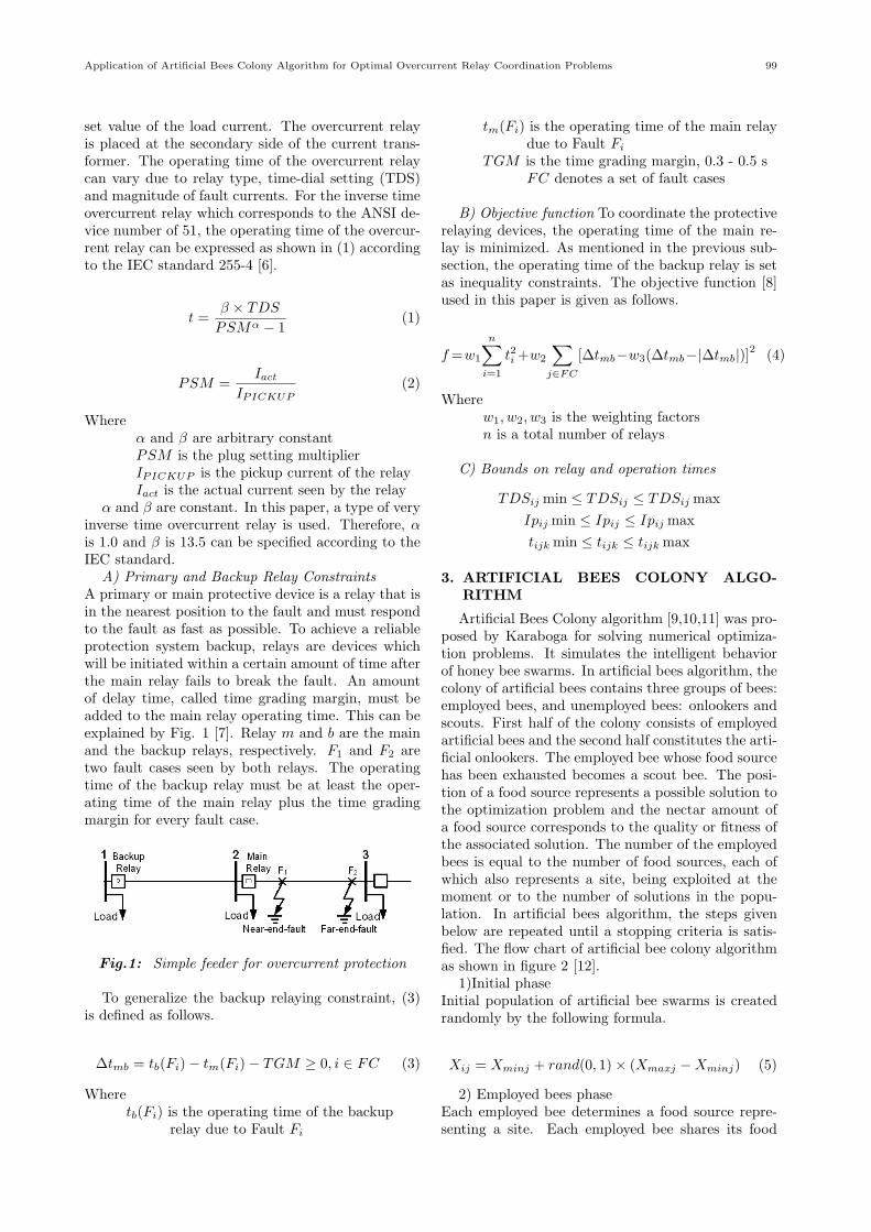
A) Primary and Backup Relay ConstraintsA primary or main protective device is a relay that isin the nearest position to the fault and must respondto the fault as fast as possible. To achieve a reliableprotection system backup, relays are devices whichwill be initiated within a certain amount of time afterthe main relay fails to break the fault. An amountof delay time, called time grading margin, must beadded to the main relay operating time. This can beexplained by Fig. 1 [7]. Relay m and b are the mainand the backup relays, respectively. F1 and F2 aretwo fault cases seen by both relays. The operatingtime of the backup relay must be at least the oper-ating time of the main relay plus the time gradingmargin for every fault case.
Fig.1: Simple feeder for overcurrent protection
To generalize the backup relaying constraint, (3)is defined as follows.
∆tmb = tb(Fi)− tm(Fi)− TGM ≥ 0, i ∈ FC (3)
Wheretb(Fi) is the operating time of the backup
relay due to Fault Fi
tm(Fi) is the operating time of the main relaydue to Fault Fi
TGM is the time grading margin, 0.3 - 0.5 sFC denotes a set of fault cases
B) Objective function To coordinate the protectiverelaying devices, the operating time of the main re-lay is minimized. As mentioned in the previous sub-section, the operating time of the backup relay is setas inequality constraints. The objective function [8]used in this paper is given as follows.
f=w1
n∑i=1
t2i +w2
∑j∈FC
[∆tmb−w3(∆tmb−|∆tmb|)]2 (4)
Wherew1, w2, w3 is the weighting factorsn is a total number of relays
C) Bounds on relay and operation times
TDSij min ≤ TDSij ≤ TDSij max
Ipij min ≤ Ipij ≤ Ipij max
tijk min ≤ tijk ≤ tijk max
3. ARTIFICIAL BEES COLONY ALGO-RITHM
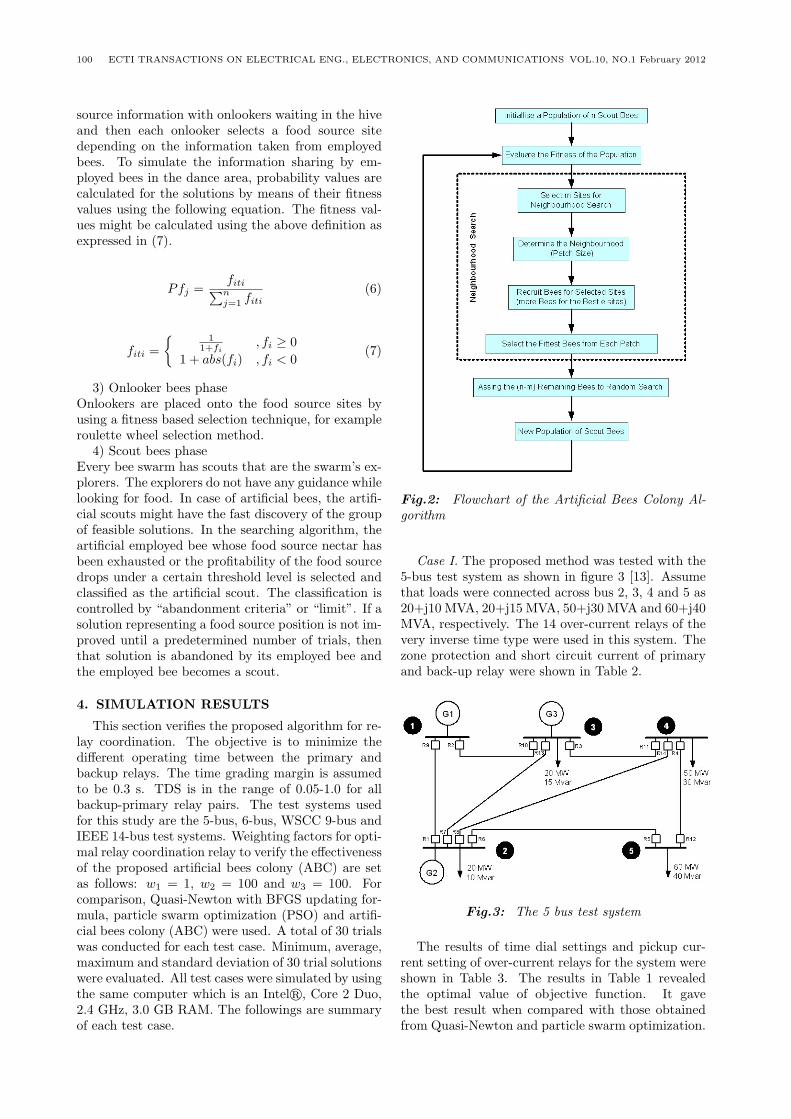
Artificial Bees Colony algorithm [9,10,11] was pro-posed by Karaboga for solving numerical optimiza-tion problems. It simulates the intelligent behaviorof honey bee swarms. In artificial bees algorithm, thecolony of artificial bees contains three groups of bees:employed bees, and unemployed bees: onlookers andscouts. First half of the colony consists of employedartificial bees and the second half constitutes the arti-ficial onlookers. The employed bee whose food sourcehas been exhausted becomes a scout bee. The posi-tion of a food source represents a possible solution tothe optimization problem and the nectar amount ofa food source corresponds to the quality or fitness ofthe associated solution. The number of the employedbees is equal to the number of food sources, each ofwhich also represents a site, being exploited at themoment or to the number of solutions in the popu-lation. In artificial bees algorithm, the steps givenbelow are repeated until a stopping criteria is satis-fied. The flow chart of artificial bee colony algorithmas shown in figure 2 [12].
1)Initial phaseInitial population of artificial bee swarms is createdrandomly by the following formula.
Xij = Xminj + rand(0, 1)× (Xmaxj −Xminj) (5)
2) Employed bees phaseEach employed bee determines a food source repre-senting a site. Each employed bee shares its food
100 ECTI TRANSACTIONS ON ELECTRICAL ENG., ELECTRONICS, AND COMMUNICATIONS VOL.10, NO.1 February 2012
source information with onlookers waiting in the hiveand then each onlooker selects a food source sitedepending on the information taken from employedbees. To simulate the information sharing by em-ployed bees in the dance area, probability values arecalculated for the solutions by means of their fitnessvalues using the following equation. The fitness val-ues might be calculated using the above definition asexpressed in (7).
Pfj =fiti∑nj=1 fiti
(6)
fiti =
{1
1+fi, fi ≥ 0
1 + abs(fi) , fi < 0(7)
3) Onlooker bees phaseOnlookers are placed onto the food source sites byusing a fitness based selection technique, for exampleroulette wheel selection method.
4) Scout bees phaseEvery bee swarm has scouts that are the swarm’s ex-plorers. The explorers do not have any guidance whilelooking for food. In case of artificial bees, the artifi-cial scouts might have the fast discovery of the groupof feasible solutions. In the searching algorithm, theartificial employed bee whose food source nectar hasbeen exhausted or the profitability of the food sourcedrops under a certain threshold level is selected andclassified as the artificial scout. The classification iscontrolled by “abandonment criteria” or “limit”. If asolution representing a food source position is not im-proved until a predetermined number of trials, thenthat solution is abandoned by its employed bee andthe employed bee becomes a scout.
4. SIMULATION RESULTS
This section verifies the proposed algorithm for re-lay coordination. The objective is to minimize thedifferent operating time between the primary andbackup relays. The time grading margin is assumedto be 0.3 s. TDS is in the range of 0.05-1.0 for allbackup-primary relay pairs. The test systems usedfor this study are the 5-bus, 6-bus, WSCC 9-bus andIEEE 14-bus test systems. Weighting factors for opti-mal relay coordination relay to verify the effectivenessof the proposed artificial bees colony (ABC) are setas follows: w1 = 1, w2 = 100 and w3 = 100. Forcomparison, Quasi-Newton with BFGS updating for-mula, particle swarm optimization (PSO) and artifi-cial bees colony (ABC) were used. A total of 30 trialswas conducted for each test case. Minimum, average,maximum and standard deviation of 30 trial solutionswere evaluated. All test cases were simulated by usingthe same computer which is an Intelr, Core 2 Duo,2.4 GHz, 3.0 GB RAM. The followings are summaryof each test case.
Fig.2: Flowchart of the Artificial Bees Colony Al-gorithm
Case I. The proposed method was tested with the5-bus test system as shown in figure 3 [13]. Assumethat loads were connected across bus 2, 3, 4 and 5 as20+j10 MVA, 20+j15 MVA, 50+j30 MVA and 60+j40MVA, respectively. The 14 over-current relays of thevery inverse time type were used in this system. Thezone protection and short circuit current of primaryand back-up relay were shown in Table 2.
Fig.3: The 5 bus test system
The results of time dial settings and pickup cur-rent setting of over-current relays for the system wereshown in Table 3. The results in Table 1 revealedthe optimal value of objective function. It gavethe best result when compared with those obtainedfrom Quasi-Newton and particle swarm optimization.
Application of Artificial Bees Colony Algorithm for Optimal Overcurrent Relay Coordination Problems 101
Table 1: Computational results for the 5-bus testsystem.
Table 2: Primary and backup information for the5-bus test system.
Table 3: Optimal time dial setting and pick-up cur-rent for the 5-bus system
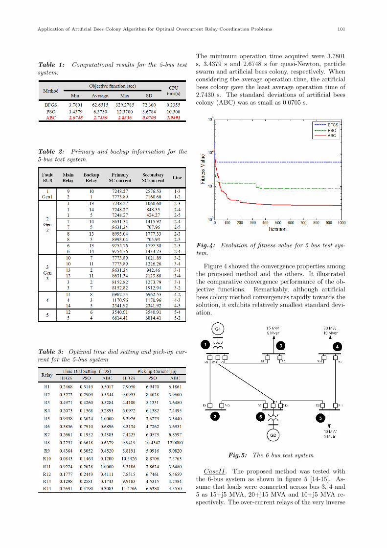
The minimum operation time acquired were 3.7801s, 3.4379 s and 2.6748 s for quasi-Newton, particleswarm and artificial bees colony, respectively. Whenconsidering the average operation time, the artificialbees colony gave the least average operation time of2.7430 s. The standard deviations of artificial beescolony (ABC) was as small as 0.0705 s.
Fig.4: Evolution of fitness value for 5 bus test sys-tem.
Figure 4 showed the convergence properties amongthe proposed method and the others. It illustratedthe comparative convergence performance of the ob-jective functions. Remarkably, although artificialbees colony method convergences rapidly towards thesolution, it exhibits relatively smallest standard devi-ation.
Fig.5: The 6 bus test system
CaseII. The proposed method was tested withthe 6-bus system as shown in figure 5 [14-15]. As-sume that loads were connected across bus 3, 4 and5 as 15+j5 MVA, 20+j15 MVA and 10+j5 MVA re-spectively. The over-current relays of the very inverse
102 ECTI TRANSACTIONS ON ELECTRICAL ENG., ELECTRONICS, AND COMMUNICATIONS VOL.10, NO.1 February 2012
time type were used. Information of this test case wasshown in Table 4.
Table 4: Primary and backup information for the6-bus test system
Table 5: Optimal time dial setting and pick-up cur-rent for the 6-bus system
Table 6: Computational results for the 6-bus testsystem.
The results of the optimal setting value for 14 over-current relays of the 6-bus test system were presented
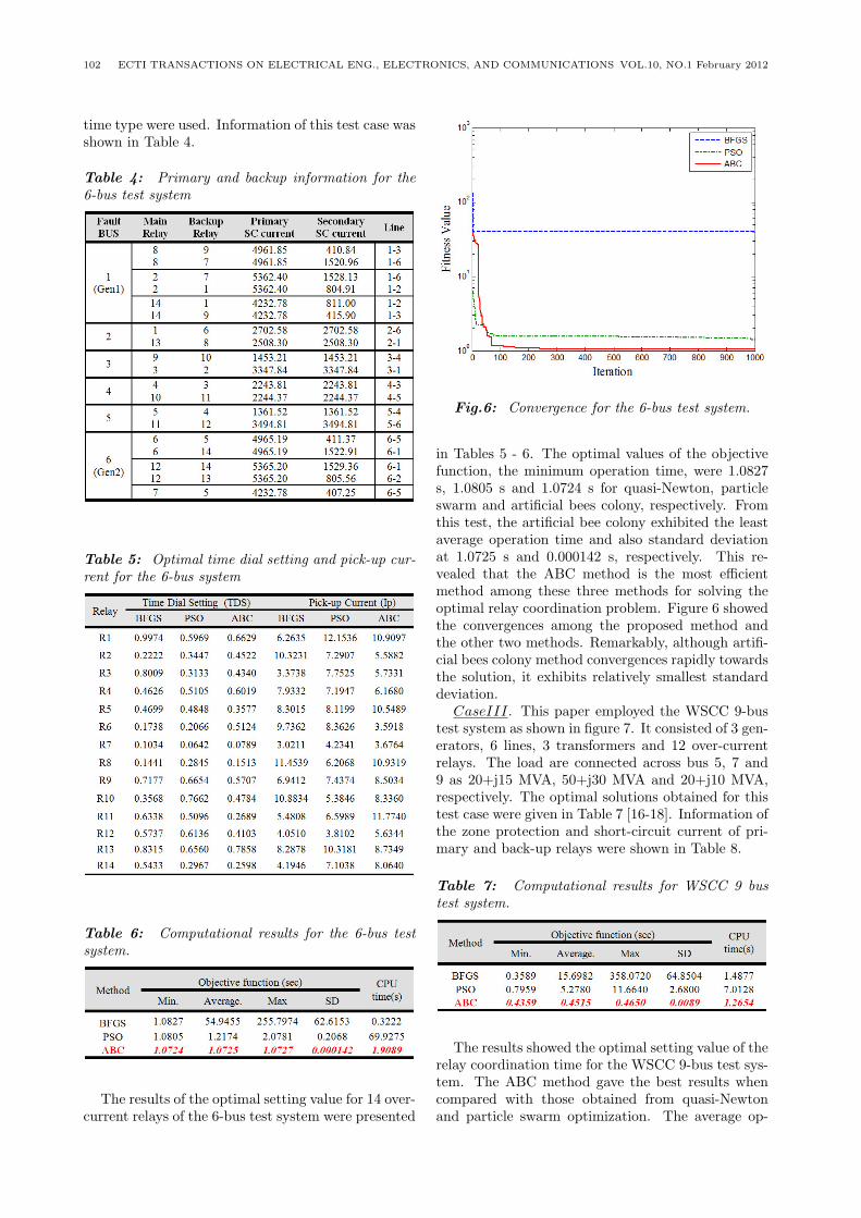
Fig.6: Convergence for the 6-bus test system.
in Tables 5 - 6. The optimal values of the objectivefunction, the minimum operation time, were 1.0827s, 1.0805 s and 1.0724 s for quasi-Newton, particleswarm and artificial bees colony, respectively. Fromthis test, the artificial bee colony exhibited the leastaverage operation time and also standard deviationat 1.0725 s and 0.000142 s, respectively. This re-vealed that the ABC method is the most efficientmethod among these three methods for solving theoptimal relay coordination problem. Figure 6 showedthe convergences among the proposed method andthe other two methods. Remarkably, although artifi-cial bees colony method convergences rapidly towardsthe solution, it exhibits relatively smallest standarddeviation.
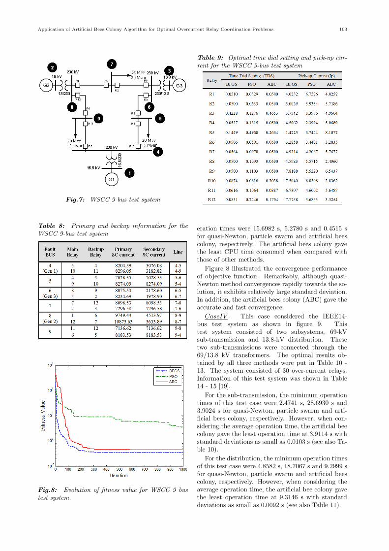
CaseIII. This paper employed the WSCC 9-bustest system as shown in figure 7. It consisted of 3 gen-erators, 6 lines, 3 transformers and 12 over-currentrelays. The load are connected across bus 5, 7 and9 as 20+j15 MVA, 50+j30 MVA and 20+j10 MVA,respectively. The optimal solutions obtained for thistest case were given in Table 7 [16-18]. Information ofthe zone protection and short-circuit current of pri-mary and back-up relays were shown in Table 8.
Table 7: Computational results for WSCC 9 bustest system.
The results showed the optimal setting value of therelay coordination time for the WSCC 9-bus test sys-tem. The ABC method gave the best results whencompared with those obtained from quasi-Newtonand particle swarm optimization. The average op-
Application of Artificial Bees Colony Algorithm for Optimal Overcurrent Relay Coordination Problems 103
Fig.7: WSCC 9 bus test system
Table 8: Primary and backup information for theWSCC 9-bus test system
Fig.8: Evolution of fitness value for WSCC 9 bustest system.
Table 9: Optimal time dial setting and pick-up cur-rent for the WSCC 9-bus test system
eration times were 15.6982 s, 5.2780 s and 0.4515 sfor quasi-Newton, particle swarm and artificial beescolony, respectively. The artificial bees colony gavethe least CPU time consumed when compared withthose of other methods.
Figure 8 illustrated the convergence performanceof objective function. Remarkably, although quasi-Newton method convergences rapidly towards the so-lution, it exhibits relatively large standard deviation.In addition, the artificial bees colony (ABC) gave theaccurate and fast convergence.
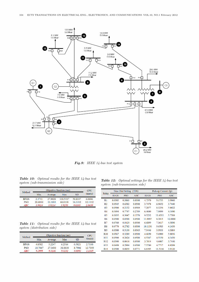
CaseIV . This case considered the IEEE14-bus test system as shown in figure 9. Thistest system consisted of two subsystems, 69-kVsub-transmission and 13.8-kV distribution. Thesetwo sub-transmissions were connected through the69/13.8 kV transformers. The optimal results ob-tained by all three methods were put in Table 10 -13. The system consisted of 30 over-current relays.Information of this test system was shown in Table14 - 15 [19].
For the sub-transmission, the minimum operationtimes of this test case were 2.4741 s, 28.6930 s and3.9024 s for quasi-Newton, particle swarm and arti-ficial bees colony, respectively. However, when con-sidering the average operation time, the artificial beecolony gave the least operation time at 3.9114 s withstandard deviations as small as 0.0103 s (see also Ta-ble 10).
For the distribution, the minimum operation timesof this test case were 4.8582 s, 18.7067 s and 9.2999 sfor quasi-Newton, particle swarm and artificial beescolony, respectively. However, when considering theaverage operation time, the artificial bee colony gavethe least operation time at 9.3146 s with standarddeviations as small as 0.0092 s (see also Table 11).
104 ECTI TRANSACTIONS ON ELECTRICAL ENG., ELECTRONICS, AND COMMUNICATIONS VOL.10, NO.1 February 2012
Fig.9: IEEE 14-bus test system
Table 10: Optimal results for the IEEE 14-bus testsystem (sub-transmission side)
Table 11: Optimal results for the IEEE 14-bus testsystem (distribution side)
Table 12: Optimal settings for the IEEE 14-bus testsystem (sub-transmission side)
Application of Artificial Bees Colony Algorithm for Optimal Overcurrent Relay Coordination Problems 105
Table 13: Optimal settings for the IEEE 14-bus testsystem (distribution side)
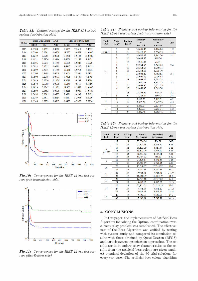
Fig.10: Convergences for the IEEE 14-bus test sys-tem (sub-transmission side)
Fig.11: Convergences for the IEEE 14-bus test sys-tem (distribution side)
Table 14: Primary and backup information for theIEEE 14-bus test system (sub-transmission side)
Table 15: Primary and backup information for theIEEE 14-bus test system (distribution side)
5. CONCLUSIONS
In this paper, the implementation of Artificial BeesAlgorithm for solving the Optimal coordination over-current relay problem was established. The effective-ness of the Bees Algorithm was verified by testingwith system study and compared its simulation re-sults with those obtained by Quasi-Newton (BFGS)and particle swarm optimization approaches. The re-sults are in boundary relay characteristics as the re-sults from the artificial bees colony are given small-est standard deviation of the 30 trial solutions forevery test case. The artificial bees colony algorithm
106 ECTI TRANSACTIONS ON ELECTRICAL ENG., ELECTRONICS, AND COMMUNICATIONS VOL.10, NO.1 February 2012
can converge towards the better solution slightly todecrease on small system, it can be considered as apotential alternative that is suitable for solving therelay coordination problem.
References
[1] P.M. Anderson, Power System Protection, IEEEPress., McGraw-Hill, 1999.
[2] J. L. Blackburn, Protective Relaying: Principlesand Applications, Marcel Dekker, 1987.
[3] V. Rashtchi , J. Gholinezhad and P. Farhang,“Optimal coordination of overcurrent relaysusing Honey Bee algorithm,” Ultra ModernTelecommunications and Control Systems andWorkshops (ICUMT) 2010., pp. 401 - 405.
[4] C. Sumpavakup, I. Srikun and S. Chusanapiputt,“A solution to the Optimal Power Flow usingArtificial Bee Colony algorithm,” Power SystemTechnology (POWERCON), 2010., pp.1 - 5 .
[5] Walter A. Elmore , Protective Relay Theory andApplications, ABB Power T&D Company Inc.,1994.
[6] IEC Standard 255-4.[7] A.J. Urdaneta, R. Nadira, L.G.P. Jimenez, “Op-
timal coordination of directional overcurrent re-lays in interconnected power systems,” IEEETransactions on Power Delivery, Vol. 3, pp. 903-911, 1988.
[8] D. Uthitsunthorn, and T. Kulworawanichpong,“Optimal Overcurrent Relay Coordination usingGenetic Algorithms,” International Conferenceon Advanced Energy Engineering (ICAEE 2010),19-20 June 2010, pp. 162 - 165.
[9] U. Kwannetr, U. Leeton and T. Kulworawanich-pong, “Optimal power flow using artificial beesalgorithm,” Advances in Energy EngineeringICAEE 2010,pp.215 - 218.
[10] N.T. Linh and N.Q. Anh, “Application of artifi-cial bee colony algorithm (ABC) for reconfigur-ing distribution network,” International Confer-ence on Computer Modellingand Simulation, pp.102-106.
[11] D. Karaboga and B. Busturk, “A powerful andefficient algorithm for numerical function op-timization: artificial bee colony optimization,”Journal of Global Optimization, Vol.39, pp. 459-471.
[12] N. Sinsuphun,U. Leeton,U. Kwannetr,D.Uthitsunthorn and T. Kulworawanich-pong, “Loss Minimization Using Optimal PowerFlowBased on Swarm Intelligences,” ECTITransactions on Electrical Eng.,Electronics,And Communications, Vol.9, No.1, pp.212-222,2011.
[13] Y. Wallach, Calculation and programs for powerSystem networks, New Jersy, Prentice-hall, 1996.
[14] Hossein K. K., Hossein A. A., Vivian O., MatinM., “Pre-processing of the optimal coordination
of overcurrent relays,” Electric Power SystemsResearch, Vol.75, pp. 134-141, 2005.
[15] F. Razavi, H. A. Abyaneh, M. Al-Dabbagh,R.Mohammadi and H. Torkaman, “A new com-prehensive genetic algorithm method for optimalovercurrent relays coordination,” Electric PowerSystems Research, Vol. 78, pp. 713-720, 2008.
[16] Y. Xingbin and S. Chanan, “Probabilistic powersystem security analysis considering protectionfailures,” The International Journal for Compu-tation and Mathematics in Electrical and Elec-tronic Engineering, Vol. 23 , 2004 .
[17] WSCC (West Systems Coordination Council)(1996), West Systems Coordinating Council, Fi-nal Report, 10 August 1996.
[18] D. Uthitsunthorn, P. Pao-La-Or and T.Kulworawa-nichpong, “Optimal OvercurrentRelay Coordination Using Artificial Bees ColonyAlgorithm,” Electrical Engineering/Electronics,Computer, Telecommunica-tion and InformationTechnology (ECTI-CON 2011), pp. 901 - 904.
[19] J. Arrillaga, N.R. Watson, S. Chen, Power Sys-tem Quality Assessment, Wiley, UK, 2000.
Dusit Uthitsunthorn received theMaster of Electrical Engineering de-gree from King Mongkut’s Univer-sity of Technology North Bangkok(KMUTNB), Thailand in 2007. Cur-rently he is a Ph.D. Student anda research assistant at Power Sys-tem Research Unit, Suranaree Univer-sity of Technology, Nakhon Ratchasima,THAILAND. His research interest in-cludes power system, power system in-
telligent protection and optimization technique.
Padej Pao-la-or is an assistant profes-sor of the School of Electrical Engineer-ing, Institute of Engineering, Surana-ree University of Technology, NakhonRatchasima, THAILAND. He receivedB.Eng. (1998), M.Eng. (2002) andD.Eng. (2006) in Electrical Engineer-ing from Suranaree University of Tech-nology, Thailand. His fields of researchinterest include a broad range of powersystems, electrical drives, FEM simula-
tion and artificial intelligent techniques. He has joined theschool since December 2005 and is currently a member in PowerSystem Research, Suranaree University of Technology.
Thanatchai Kulworawanichpong isan associate professor of the School ofElectrical Engineering, Institute of En-gineering, Suranaree University of Tech-nology, Nakhon Ratchasima, THAI-LAND. He received B.Eng. with first-class honour in Electrical Engineeringfrom Suranaree University of Technol-ogy, Thailand (1997), M.Eng. in Elec-trical Engineering from Chulalongkorn

Application of Artificial Bees Colony Algorithm for Optimal Overcurrent Relay Coordination Problems 107
University, Thailand (1999), and Ph.D.in Electronic and Electrical Engineering from the Universityof Birmingham, United Kingdom (2003). His fields of researchinterest include a broad range of power systems, power elec-tronic, electrical drives and control, optimization and artificialintelligent techniques. He has joined the school since June 1998and is currently a leader in Power System Research, SuranareeUniversity of Technology, to supervise and co-supervise over15 postgraduate students.