Embed Size (px)
Citation preview

Onyeka et al., International Journal on Emerging Technologies 12(1): 228-240(2021) 228
International Journal on Emerging Technologies 12(1): 228-240(2021)
ISSN No. (Print): 0975-8364ISSN No. (Online): 2249-3255
Application of a New Trigonometric Theory in the Buckling Analysis ofThree-Dimensional Thick Plate
Onyeka, F.C.1, Okafor, F.O.2 and Onah H.N.31Department of Civil Engineering, Edo State University Uzairue, Edo State, Nigeria.
2Department of Civil Engineering, University of Nigeria Nsukka, Nigeria.3Department of Civil Engineering, University of Nigeria Nsukka, Nigeria.
(Corresponding author: Onyeka, F.C.)(Received 08 December 2020, Revised 26 January 2021, Accepted 27 February 2021)
(Published by Research Trend, Website: www.researchtrend.net)
ABSTRACT: In this paper, a new trigonometric shear deformation plate theory is developed for the bucklinganalysis of a three dimensional thick rectangular isotropic plate, elastically restrained along one edge andother three edges simply supported (CSSS) under uniaxial compressive load, using the variational Energyapproach. Total potential energy equation of a thick plate was formulated from the three-dimensionalconstitutive relations, thereafter the compatibility equations was established to obtain the relations betweenthe out of plane displacement and shear deformation slope along the direction of x and y coordinates. Thistotal potential energy functional was differentiated with respect to deflection to obtain the governingequation. The functions for these slopes were obtained from out of plane function using the solution ofcompatibility equations while the solution of the governing equation is the function for the out of planedisplacement. Finally, the total potential energy is minimized with respect to displacement coefficients,thereafter, the deflection and rotations were substituted back into the buckling equation derived to obtain theformulas for calculating the critical buckling load and other the mentioned functions. The three dimensionalanalysis for critical buckling of thick plates were carried out by varying parameters stiffness properties andaspect ratios. The proposed method obviates the need of shear correction factors which is associated withfirst order shear deformation theory for the energy equation formulation. The present theory unlike refinedplate theories, considered all the stress elements of the plate in the analysis. From the numerical analysisobtained, it is found that the value of the critical buckling load increase as the span- thickness ratioincreases. This suggests that as the thickness increases, the safety of the plate structure is improved.
Keywords: CSSS plate, a new trigonometric plate theory, compatibility and governing equation, three-dimensionalbuckling analysis, potential energy functional.
I. INTRODUCTION
The use of thick plate materials in engineering is on theincrease over the years due to its attractive propertiessuch as light weight, economy, its ability to withstandheavy loads and ability to tailor the structural properties,etc. Plate structures can be used in roof and floor slabs,bridge deck slabs, foundation footings, bulkheads, watertanks, ship hulls and spacecraft panels.Plates can be classified into thick, membranes and thinplates, depending upon the heaviness of the plate [1].In-plane loading causes a plate to buckle or becomeelastically unstable. The plates are mostly subjected totransverse and compressive loads acting in the middleplane of the plate. When a plate is subjected to forcesapplied at the boundary parallel to the mid-plane of theplate and distributed uniformly over the plate’sthickness, the state of loading is called an in-planecompressive loading [2]. If the in-plane compressiveload applied to the plate are further increased beyondtheir critical values, very large deflections and bendingstresses will occur which will eventually lead tocomplete failure of the plate. To avoid failure of the
plate, relatively more accurate and practical studies onstability analysis of plate are required.The classical plate theory (CPT) based on Kirchhoffassumptions [3-4] are normally used to plates analysis.It was discovered the solutions based on the classicaltheory agree well with the full elasticity solutions (awayfrom the edges of the plate), provided the platethickness is small relative to its other linear dimensions.The (CPT) neglect the effect of shear deformation whichmakes it inconsistent in the sense that elements areassumed to remain perpendicular to the mid-plane, yetthe equilibrium requires that stress component whichwould cause these elements to deform still arise. Inother words, the thin plate model still makes theassumption that normal stress and strain along the zaxis ( , ) are zero. It was also assumed that thetransverse shear stress ( ) are zero. This assumptionhas discovered to have introduced errors, hence doesnot offer a very accurate analysis of plates in which thethickness-to length proportion is relatively large [5-6].When the plate is relatively thick, one is advised to usean exact theory, for example one of the sheardeformation theories.
et

Onyeka et al., International Journal on Emerging Technologies 12(1): 228-240(2021) 229
In this theory, there is the added complication thatvertical line elements before deformation do not have toremain perpendicular to the mid-surface afterdeformation, although they do remain straight [7; 8; 9].Thus shear strains are generated, constant through thethickness of the plate. Also, Mindlin’s theory satisfiesconstitutive relations for transverse shear stresses andshear strains by using shear correction factor.In avoiding shear correction factor and to get therealistic variation of the transverse shear strains andstresses through the thickness of the plate for improvedreliability in the thick plate analysis, higher order sheardeformation plate theory (HSDT) evolved [10; 11; 12;13; 14;15]. In their solution for the bending and bucklinganalysis of shear deformable plates, it was discoveredthat the thick plate model assumption does not offer amore reliable analysis of plates in which the thickness-to-length proportion is very heavy, therefore calledincomplete three-dimensional analysis.However, a thick plate is a typical three dimensionalelement and true analysis demands a complete three-dimensional analogy. A typical 3-D plate theoryconsidered a deformation of the plate in the threedirections (x, y, and z) thereby involves the twelve (12)stress/strain components in the analysis. That is, usingcompete three dimensional element for the analysis. Itcan be recorded that both first order theory (Mindlin’stheory) and other higher shear deformation incompletethree-dimensional analysis are approximations of theexact three-dimensional equations of elasticity, but for atypical thick plate analysis, a typical 3-D plate theory isrequired [16].Equally well, no much work has been performed along atypical three dimensional element stability analysis ofthick plate by determining the exact displacementfunction from the compatibility equation to find out theoutcome of critical buckling load.
Furthermore, the trigonometric displacementfunctions can be applied successfully to solve anyboundary condition of rectangular plate; a feat that couldnot be easily achieved using exponential and hyperbolicshape functions. In addition, it is really necessary toadopt variational method to simplify a complexequations in the thick plate analysis because theintegration of double Fourier series is quite involvingunlike the present approach.The author in [16] studied the 3-D elasticity bucklingsolution for simply supported thick rectangular platesusing displacement potential functions approach and anassumed displacement functions, thereafter thegoverning differential equations were established usingseparation of variables method and satisfying the exactboundary conditions, an analytical solution is obtained
for linear elastic buckling of simply supportedrectangular thick plates. They neither derive thedisplacement function from the compatibility equation,nor solve for isotropic plates elastically restrained alongone the edge and other three edges simply supported.This gap in the literature is worth filling.This work is aimed at bridging the gap in literature bydeveloping a new trigonometric displacement theoryand applied in the exact three-dimensional stabilityanalysis of isotropic thick rectangular plate subjected toan in-plane loading. The main objective of this study isto determine a realistic formula for calculating the criticalbuckling load of thick rectangular plate elasticallyrestrained along one the edge and other three edgessimply supported (CSSS) under uniaxial compressiveload, using the variational Energy approach. The studysought to achieve the main through the followingspecific objectives:
-To generate the potential energy of a threedimensional rectangular thick plate.-To formulate the general governing andcompatibility equations of the plate and obtainequations for the coefficients of deflection andshear deformation slope for x and y coordinates.- To determine the expressions for the criticalbuckling load of the plate.
II. MATERIAL AND METHODS
A. MethodologyThe processes involved in the formulation of the totalpotential energy of a thick rectangular plate includeskinematics relations and three-dimensional constitutiverelations; formulation of strain energy and Potentialenergy.Basic assumptions. The basic assumptions for threedimensional analyses of refined shear deformation thickcontinuum plate of small deflection theorems include thefollowing:(i) The plate material is elastic, homogenous andisotropic.(ii) The middle surface of the flat plate never stretchesnor compresses before, during or after bending.(iii) A flat x-z or y-z section, which is normal to middle x-y plane before bending shall no longer remain normal tothe middle x-y surface after bending.Kinematics Relations. Our formulation of energyequation for the stability analysis thick rectangular plateunder compressive load will be based on figure 1, figure2 and assumptions made in the previous section. Asshown in figure 1, the spatial dimensions of the platealong x, y and z-axes are a, b and t respectively.

Onyeka et al., International Journal on Emerging Technologies 12(1): 228-240(2021) 230
Fig. 1. A rectangular thick plate element showing the in-plane compressive loading.
As shown in the figure 2, the displacement field includesthe displacements along x, y and z-axes: u, v and wrespectively. The displacement and slope along the xaxis and y axis are mathematically expressed as:= w(x, y, z) = h (1)
= (2) = (3)Considering assumption iii and figure 1, F as used is afunction of z coordinate. Thus, the in-planedisplacements; u and v as presented in the Equation 2and 3 are further defined using trigonometric relationsfor small angles as:= ( ) = (4)= ( ) = (5)Where:The symbol denotes deflection, the symboldenotes in-plane displacement along x-axis, the symbol
denotes in-plane displacement along y-axis, thesymbol denotes shear deformation rotation along xaxis, the symbol denotes shear deformation rotationalong the y axis, and denotes shear deformationprofile.Substituting Equation 2 and 3 into Equation 4 and 5gives:= F(z) (6)= F(z) (7)
Fig. 2. Displacement of x-z (or y-z).
Taking the non-dimensional form of coordinates to be R= x/a, Q = y/b and S = z/t corresponding to x, y and z-axes respectively, the six strain components in terms ofnon-dimensional coordinates are written as:
= θ (8) = θ (9) = 1 (10) = θ + θ (11) = θ + 1 (12) = θ + 1 (13)
Where:the symbol denotes normal strain along x axis, thesymbol denotes normal strain along y axis, thesymbol denotes normal strain along z axis, thesymbol denotes shear strain in the plane parallel tothe x-y plane, the symbol denotes shear strain in theplane parallel to the x-z plane, the symbol denotesshear strain in the plane parallel to the y-z plane.
Constitutive Relations. In the constitutive relation, thestresses causing the body movements are consideredhere. These stresses are described using generalizedHooke’s law, therefore, the three dimensionalconstitutive relation for isotropic material is given as:
⎣⎢⎢⎢⎢⎡
εεεγγγ ⎦⎥⎥⎥⎥⎤
= 1E ⎣⎢⎢⎢⎢⎡1 −μ −μ 0 0 0−μ 1 −μ 0 0 0−μ −μ 1 0 0 00 0 0 2(1 + μ) 0 00 0 0 0 2(1 + μ) 00 0 0 0 0 2(1 + μ)⎦⎥⎥
⎥⎥⎤⎣⎢⎢⎢⎢⎡σσστττ ⎦⎥⎥⎥⎥⎤ (14)
Young’s modulus of elasticity and Poisson’s ratios aredenoted with E and µ respectively.
Onyeka et al., International Journal on Emerging Technologies 12(1): 228-240(2021) 231
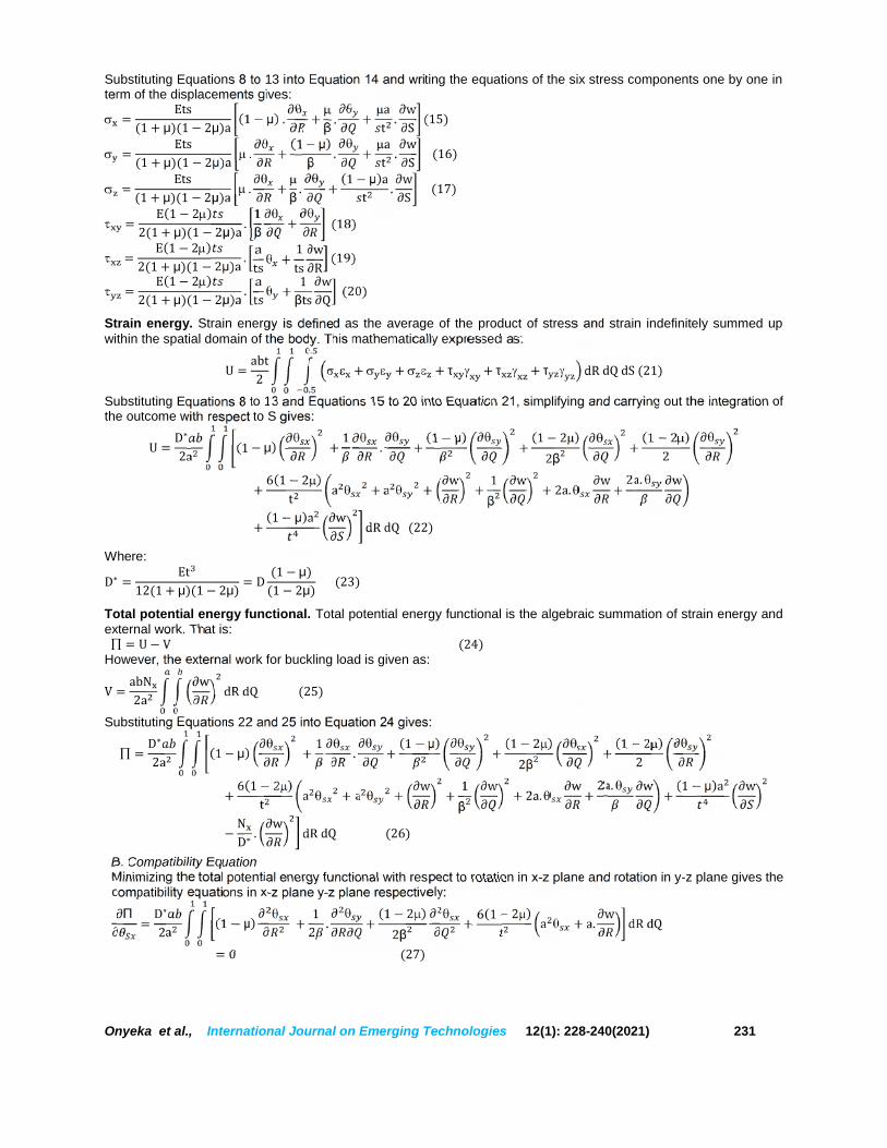
Substituting Equations 8 to 13 into Equation 14 and writing the equations of the six stress components one by one interm of the displacements gives:
= Ets(1 + μ)(1 − 2μ)a (1 − μ) . + β. + at . ∂w∂S (15)
= Ets(1 + μ)(1 − 2μ)a . + (1 − μ)β
. + at . ∂w∂S (16) = Ets(1 + μ)(1 − 2μ)a . + β . + (1 − μ)at . ∂w∂S (17) = E(1 − 2)2(1 + μ)(1 − 2μ)a . 1β + (18) = E(1 − 2)2(1 + μ)(1 − 2μ)a . ats + 1ts ∂w∂R (19) = E(1 − 2)2(1 + μ)(1 − 2μ)a . ats + 1βts ∂w∂Q (20)Strain energy. Strain energy is defined as the average of the product of stress and strain indefinitely summed upwithin the spatial domain of the body. This mathematically expressed as:U = abt2 + + + τ + τ + τ
.. dR dQ dS (21)
Substituting Equations 8 to 13 and Equations 15 to 20 into Equation 21, simplifying and carrying out the integration ofthe outcome with respect to S gives:U = D∗2a (1 − μ) + 1 . + (1 − μ) + (1 − 2)2β + (1 − 2)2
+ 6(1 − 2)t a + a + w + 1β
w + 2a. w+ 2a. w+ (1 − μ)a w dR dQ (22)
Where:D∗ = Et12(1 + μ)(1 − 2μ) = D (1 − μ)(1 − 2μ) (23)Total potential energy functional. Total potential energy functional is the algebraic summation of strain energy andexternal work. That is: = U − V (24)
However, the external work for buckling load is given as:V = abN2a w dR dQ (25)Substituting Equations 22 and 25 into Equation 24 gives:
= D∗2a (1 − μ) + 1 . + (1 − μ) + (1 − 2)2β + (1 − 2)2
+ 6(1 − 2)t a + a + w + 1β
w + 2a. w+ 2a. w + (1 − μ)a w− ND∗ . w dR dQ (26)
B. Compatibility EquationMinimizing the total potential energy functional with respect to rotation in x-z plane and rotation in y-z plane gives thecompatibility equations in x-z plane y-z plane respectively:
Π = D∗2a (1 − μ) + 12 . + (1 − 2)2β + 6(1 − 2)t a + a. w dR dQ= 0 (27)

Onyeka et al., International Journal on Emerging Technologies 12(1): 228-240(2021) 232
Π = D∗2a 12 . + (1 − μ) + (1 − 2)2 + 6(1 − 2)t a + a. w dR dQ= 0 (28)For Equations 27 and 28 to be true, their integrands must be zero. That is:(1 − μ) + 12 . + (1 − 2)2β + 6(1 − 2)t a + a. w = 0 (29) 3112 . + (1 − μ) + (1 − 2)2 + 6(1 − 2)t a + a. w = 0 (30) 32Using law of addition, the Equations 12 and 13 will be simplified and substituted into Equations 29 and 30respectively, then factorizing the outcome gives:(1 − μ) + 1 . (1 − ) + 6(1 − 2)at . 1 + 1 = 0 (31)1 . w (1 − μ) + (1 − μ) + 6(1 − 2)at . 1 + 1 = 0 (32)One of the possibilities of Equation 31 to be true is for the terms in the bracket to sum to zero. Adding terms in thebrackets of Equation 31 and 32 gives:6(1 − 2)(1 + )t = −c(1 − μ)a + 1 (33)C. General Governing EquationThe general governing equation is obtained by minimizing the total potential energy functional with respect todeflection. That is:
Π = D∗2a 12(1 − 2)t w + 1β. w + a. + a + 2 (1 − μ)a . w − 2ND∗ . w dR dQ= 0 (34)
Substituting the simplified Equations 12 and 13 into Equation 34 and simplifying the outcome gives:D∗2a 6(1 − 2)(1 + c)t w + 1β. w + (1 − μ)a w − ND∗ . w dR dQ = 0 (35)
Let:= w .w .w (36)= w .w (37)w = w .w (38)N = N + N (39)Substituting Equation 37, 38 and 33 into Equation 35 and simplifying the outcome gives: gives:D∗2a w + 2
β. w + 1
β. w − N agD∗ . w w + wg (1 − μ)a . w − N aD∗ . w dR dQ = 0 (40)
For Equation 40 to be true, its integrand must be zero. That is:w + 2β. w + 1
β. w − N agD∗ . w w + wg (1 − μ)a . w − N aD∗ . w= 0 (41)
One of the possibilities of Eqn. 41 to be true is for the terms in each of the two brackets sum to zero. That is:w + 2β. w + 1
β. w − N agD∗ . w = 0 (42)(1 − μ)a . w − N aD∗ . w = 0 (43)
Eqns. 42 and 43 are the two Governing Equations of a 3-dimensional rectangular plate subject to pure buckling.Thus, the exact solution to the differential equation of Equation 42 is in trigonometric form gives:
w = [1 ( ) ( )] . [1 ( ) ( )] (44)Recall from Equation 1, w = . ℎ and ws is only differential along z-axis. Hence, it is constant along x-axis and y-axis. Thus, Substituting Equation 45 into Equation 37, gives;

Onyeka et al., International Journal on Emerging Technologies 12(1): 228-240(2021) 233
w = ∆ [1 ( ) ( )] . [1 ( ) ( )] (45)Where:w = ∆ + ∆ S (46)And,w = ∆ (47)Substituting Equation 45 into the simplified Equations 12 and 13 and simplifying the outcome gives:
= . ∆ . [1 ( ) ( )] . [1 ( ) ( )] (48) =
β. ∆ . [1 ( ) ( )] . [1 ( ) ( )] (49)
In symbolic forms, Equations 48 and 49 are:
= . ℎ (50) =
β. ℎ (51)
D. Direct Governing EquationThe governing equation is obtained by minimizing the total potential energy functional with respect to deflectioncoefficient.Substituting Equations (1),(50) and (51) into Equation (26) gives:
= D∗2a (1 − μ) + 1 . + (1 − 2)2 + (1 − 2)2 + (1 − μ)+ 6(1 − 2) a + + 2 . + 1
β. + + 2 .
− N aD∗ . (52)Where:= ℎ : = ℎ ; = ℎ ;= ℎ ; = ℎ
Minimizing Equation 52 with respect to A2R and A2Q and Solving Equations simultaneously gives respectively:= (53)= (54)Where:= ( − )( − ) ; = ( − )( − )= (1 − μ) + 12 (1 − 2) + 6(1 − 2) a= (1 − μ) + 12β (1 − 2) + 6
β(1 − 2) a= = 12 ; = −6(1 − 2) a ; = = − 6
β(1 − 2) a
Minimizing Equation 52 with respect to A1 gives:Π = 6(1 − 2) a [ + ]. + 1
β. [ + ]. − N aD∗ . = 0 (55)
Substituting Equations 53 and 54 into Equation 55 and rearranging gives:

Onyeka et al., International Journal on Emerging Technologies 12(1): 228-240(2021) 234
N aD∗ = 6(1 − 2) a [1 + ] + 1β. [1 + ]. (56)
This gives:a N = (1 + μ)2 a [1 + ] + 1β. [1 + ]. (57)
III. NUMERICAL ANALYSIS
Considering Fig. 3, the numerical analysis of CSSS rectangular plate will be performed to determine the value of thecritical buckling load at various span-thickness ratios. A trigonometric displacement function for the analysis CSSSplate was derived according to author in [17] as presented in Equation (45).
Fig. 3. CSSS Rectangular Plate subjected to uniaxial compressive load.
Equation 45 can be re-written as:(∋,∈) = + + ( ) + ( ) . + + ( ) + ( ) (58)At = = 0; = 0 (59)At = = 1; . = = 0 (60)At = = 1; ∪= 0 (61)At = 0; . = 0 (62)Substituting Equations (59 to 62) into Equation (45) and solving gives the following constants:= 0; 2 + − 2 (63)The value of that satisfies Equation (61) is:= [ ℎ = 1, 2, 3… ]; = 4.49340946 (64)Substituting Equation (64) into (45) and its differentials thereby satisfying the boundary conditions of equation (59 to63) gave;= = = 0; = ; = − (65)Substituting the constants of Equation (67) into Equation (47) gives;= ( . ) × ( − − + ) (66)That is:∪= × ( ). ( − − + ) (67)Recall from Equation 26, that;= ℎ.Let the amplitude,= × (68)And;ℎ = ( ). ( − − + ) (69)Thus, the trigonometric deflection functions after satisfying the boundary conditions is= ( ). ( − − + ). (70)IV. RESULTS AND DISCUSSIONS
The result of stiffness coefficients for deflection of rectangular thick analysis subjected to of CSSS boundary conditionwere obtained using the trigonometric functions as obtained in Equation 70 and presented in Table 1. The Poisson’sratio of the plate is 0.25.
Table 1: The trigonometric stiffness coefficients of deflection function for CSSS plate.
Deflection formTrigonometry CSSS 928.2428 1,015.280 2,057.980 94.05066 102.8692
The expression of the critical buckling loadπand was obtained in the previous section and the numerical
values, determined using Equation 58 and 59 respectively. Table 2 and 3 contains the result of the non-dimensional

Onyeka et al., International Journal on Emerging Technologies 12(1): 228-240(2021) 235
values of the critical buckling load for an isotropic rectangular thick plate elastically restrained along one the edgesand other three edges simply supported (CSSS) under uniaxial compressive load at varying aspect ratio.For the non-dimensional values obtained in Table 3 and 4, it reveals that the values of critical buckling load increaseas the span- thickness ratio increases. This load increase continues until failure occurs. This means that a decreasein plate thickness increases the chance of failure in a plate structure. This means that the plate structure is not safeand needed to be maintained. To avoid this, the designer should consider higher thickness or increase the span-thickness ratio of the plate. Furthermore, it can be deduced that as the in-plane load on the plate increase andapproaches the critical buckling, the failure in a plate structure is a bound to occur.
Table 2: Non-dimensionalCritical Buckling Load on the CSSS Rectangular Plate Using TrigonometricFunction.N = N a
∝= = 1.0 = 1.5 = 2.0 = 2.5 = 3.0 = 3.5 = 4.0 = 4.5 = 5.04 4.3145 2.1634 1.5734 1.3356 1.2166 1.1484 1.1057 1.0771 1.05705 4.8168 2.3330 1.6761 1.4151 1.2854 1.2115 1.1652 1.1343 1.1126
10 5.7053 2.6057 1.8359 1.5371 1.3903 1.3072 1.2553 1.2208 1.196615 5.9076 2.6634 1.8689 1.5621 1.4117 1.3266 1.2736 1.2383 1.213520 5.9818 2.6842 1.8807 1.5710 1.4193 1.3335 1.2801 1.2445 1.219630 6.0361 2.6993 1.8892 1.5774 1.4248 1.3385 1.2848 1.2490 1.223940 6.0553 2.7046 1.8922 1.5797 1.4267 1.3403 1.2864 1.2506 1.225550 6.0642 2.7071 1.8936 1.5807 1.4276 1.3411 1.2872 1.2513 1.226260 6.0691 2.7084 1.8944 1.5813 1.4281 1.3415 1.2876 1.2517 1.226670 6.0720 2.7092 1.8949 1.5817 1.4284 1.3418 1.2879 1.2519 1.226880 6.0739 2.7097 1.8952 1.5819 1.4286 1.3419 1.2880 1.2521 1.226990 6.0752 2.7101 1.8954 1.5820 1.4287 1.3421 1.2881 1.2522 1.2270
100 6.0762 2.7103 1.8955 1.5821 1.4288 1.3422 1.2882 1.2523 1.22711000 6.0801 2.7114 1.8961 1.5826 1.4292 1.3425 1.2886 1.2526 1.22741500 6.0802 2.7114 1.8961 1.5826 1.4292 1.3425 1.2886 1.2526 1.2274
Table 3: Non-dimensional Critical Buckling Load on the CSSS Rectangular Plate using TrigonometricFunction.N = N a
∝= = 1.0 = 1.5 = 2.0 = 2.5 = 3.0 = 3.5 = 4.0 = 4.5 = 5.04 3.7851 1.8979 1.3804 1.1717 1.0673 1.0075 0.9700 0.9450 0.92735 4.2258 2.0467 1.4704 1.2414 1.1277 1.0628 1.0223 0.9952 0.9761
10 5.0052 2.2860 1.6106 1.3485 1.2197 1.1468 1.1013 1.0710 1.049715 5.1827 2.3366 1.6396 1.3704 1.2385 1.1638 1.1173 1.0863 1.064620 5.2479 2.3549 1.6499 1.3782 1.2452 1.1699 1.1230 1.0918 1.069930 5.2954 2.3681 1.6574 1.3839 1.2500 1.1743 1.1271 1.0957 1.073740 5.3123 2.3727 1.6601 1.3859 1.2517 1.1758 1.1286 1.0971 1.075150 5.3201 2.3749 1.6613 1.3868 1.2525 1.1765 1.1293 1.0978 1.075760 5.3244 2.3761 1.6620 1.3873 1.2529 1.1769 1.1296 1.0981 1.076170 5.3270 2.3768 1.6624 1.3876 1.2531 1.1771 1.1298 1.0983 1.076380 5.3286 2.3772 1.6626 1.3878 1.2533 1.1773 1.1300 1.0985 1.076490 5.3298 2.3776 1.6628 1.3879 1.2534 1.1774 1.1301 1.0986 1.0765
100 5.3306 2.3778 1.6629 1.3880 1.2535 1.1775 1.1301 1.0986 1.07651000 5.3341 2.3787 1.6635 1.3884 1.2539 1.1778 1.1304 1.0989 1.07681500 5.3341 2.3787 1.6635 1.3884 1.2539 1.1778 1.1304 1.0989 1.0768

Onyeka et al., International Journal on Emerging Technologies 12(1): 228-240(2021) 236
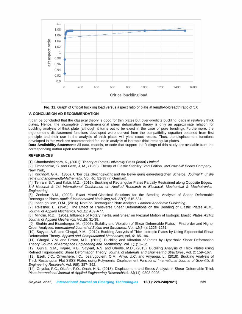
Looking closely at Fig. 4 to 12, which shows that the results of the critical buckling load of an isotropic rectangularthick plate elastically restrained along one the edge and other three edges simply supported (CSSS) under uniaxialcompressive load at varying aspect ratio. It reveals that the increase in the value of the length-breadth ratio ( =1.0, 1.5, 2.0, 2.5, 3.0, 3.5, 4.0, 4.5 and 5.0) decreases the value of the critical buckling load N . This continued untilsafety is ensured in the plate structure. In the result, it is observed that an increase in plate width increases thechance of failure in a plate structure. To maintain this, the designer should consider higher plate width or decreasethe length-breadth ratio of the plate.In summary, Table 4 to 5 and figure 4 to 10 presented here, it is observed that as the in-plane load which will causethe plate to fail by compression increases from zero to critical buckling load (N ), the buckling of the plate exceedspecified elastic limit thereby causing failure in the plate structure. This means that, the load that causes the plate todeform also causes the plate material to buckle simultaneously.
Fig. 4. Graph of Critical buckling load versus aspect ratio of a square rectangular plate.
Fig. 5. Graph of Critical buckling load versus aspect ratio of plate at length-to-breadth ratio of 1.5.
0
1
2
3
4
5
6
0 200 400 600 800 1000 1200 1400 1600
a/t a
spec
t rat
io
Critical buckling load
0
0.5
1
1.5
2
2.5
3
0 200 400 600 800 1000 1200 1400 1600
a/t a
spec
t rat
io
Critical buckling load

Onyeka et al., International Journal on Emerging Technologies 12(1): 228-240(2021) 237
Fig. 6. Graph of Critical buckling load versus aspect ratio of plate at length-to-breadth ratio of 2.0.
Fig. 7. Graph of Critical buckling load versus aspect ratio of plate at length-to-breadth ratio of 2.5.
Fig. 8. Graph of Critical buckling load versus aspect ratio of plate at length-to-breadth ratio of 3.0
0
0.2
0.4
0.6
0.8
1
1.2
1.4
1.6
1.8
0 200 400 600 800 1000 1200 1400 1600
a/t a
spec
t rat
io
Critical buckling load
1.15
1.2
1.25
1.3
1.35
1.4
1.45
0 200 400 600 800 1000 1200
a/t a
spec
t rat
io
Critical buckling load
1.05
1.1
1.15
1.2
1.25
1.3
0 200 400 600 800 1000 1200 1400 1600
a/t a
spec
t rat
io
Critical buckling load

Onyeka et al., International Journal on Emerging Technologies 12(1): 228-240(2021) 238
Fig. 9. Graph of Critical buckling load versus aspect ratio of plate at length-to-breadth ratio of 3.5
Fig. 10. Graph of Critical buckling load versus aspect ratio of plate at length-to-breadth ratio of 4.0.
Fig. 11. Graph of Critical buckling load versus aspect ratio of plate at length-to-breadth ratio of 4.5
0.981
1.021.041.061.081.11.121.141.161.181.2
0 200 400 600 800 1000 1200 1400 1600
a/t a
spec
t rat
io
Critical buckling load
0.960.981
1.021.041.061.081.11.121.141.16
0 200 400 600 800 1000 1200 1400 1600
a/t a
spec
t rat
io
Critical buckling load
0.920.940.960.981
1.021.041.061.081.11.12
0 200 400 600 800 1000 1200 1400 1600
a/t a
spec
t rat
io
Critical buckling load
Onyeka et al., International Journal on Emerging Technologies 12(1): 228-240(2021) 239
Fig. 12. Graph of Critical buckling load versus aspect ratio of plate at length-to-breadth ratio of 5.0
V. CONCLUSION AD RECOMMENDATION
It can be concluded that the classical theory is good for thin plates but over-predicts buckling loads in relatively thickplates. Hence, the incomplete three-dimensional shear deformation theory is only an approximate relation forbuckling analysis of thick plate (although it turns out to be exact in the case of pure bending). Furthermore, thetrigonometric displacement functions developed were derived from the compatibility equation obtained from firstprinciple and their use in the analysis of thick plates will yield exact results. Thus, the displacement functionsdeveloped in this work are recommended for use in analysis of isotropic thick rectangular plates.Data Availability Statement: All data, models, or code that support the findings of this study are available from thecorresponding author upon reasonable request.
REFERENCES
[1]. Chandrashekhara, K., (2001). Theory of Plates.University Press (India) Limited.[2]. Timoshenko, S. and Gere, J. M., (1963). Theory of Elastic Stability, 2nd Edition. McGraw-Hill Books Company,New York,[3]. Kirchhoff, G.R., (1850). U’’ber das Gleichgewicht and die Bewe gung einerelastschen Scheibe. Journal f’’ ur diereine und angewandteMathematik, Vol. 40: 51-88 (in German).[4]. Tehrani, B.T, and Kabir, M.Z., (2016). Buckling of Rectangular Plates Partially Restrained along Opposite Edges.3rd National & 1st International Conference on Applied Research in Electrical, Mechanical & MechatronicsEngineering.[5]. Zenkour A.M., (2003). Exact Mixed-Classical Solutions for the Bending Analysis of Shear DeformableRectangular Plates.Applied Mathematical Modelling,Vol. 27(7): 515-534.[6]. Ibearugbulem, O.M., (2016). Note on Rectangular Plate Analysis. Lambert Academic Publishing.[7]. Reissner, E., (1945). The Effect of Transverse Shear Deformations on the Bending of Elastic Plates.ASMEJournal of Applied Mechanics, Vol.12: A69-A77.[8]. Mindlin. R.D., (1951). Influence of Rotary Inertia and Shear on Flexural Motion of Isotropic Elastic Plates.ASMEJournal of Applied Mechanics, Vol.18: 31-38.[9]. Shufrin and Eisenberger, M., (2005). Stability and Vibration of Shear Deformable Plates - First order and Higher
Order Analyses. International Journal of Solids and Structures, Vol. 42(3-4): 1225–1251.[10]. Sayyad, A.S. and Ghugal, Y.M., (2012). Buckling Analysis of Thick Isotropic Plates by Using Exponential ShearDeformation Theory. Applied and Computational Mechanics, Vol. 6:185-196.[11]. Ghugal, Y.M. and Pawar, M.D., (2011). Buckling and Vibration of Plates by Hyperbolic Shear DeformationTheory. Journal of Aerospace Engineering and Technology, Vol. 1(1): 1–12.[12]. Gunjal, S.M., Hajare, R.B., Sayyad, A.S. and Ghodle, M.D., (2015). Buckling Analysis of Thick Plates usingRefined Trigonometric Shear Deformation Theory. Journal of Materials and Engineering Structures, Vol. 2: 159–167.[13]. Ezeh, J.C., Onyechere, I.C., Ibearugbulem, O.M., Anya, U.C. and Anyaogu, L., (2018). Buckling Analysis ofThick Rectangular Flat SSSS Plates using Polynomial Displacement Functions. International Journal of Scientific &Engineering Research, Vol. 9(9): 387- 392.[14]. Onyeka, F.C., Okafor, F.O., Onah, H.N., (2018). Displacement and Stress Analysis in Shear Deformable ThickPlate.International Journal of Applied Engineering ResearchVol. 13(11): 9893-9908.
0.9
0.92
0.94
0.96
0.98
1
1.02
1.04
1.06
1.08
1.1
0 200 400 600 800 1000 1200 1400 1600
a/t a
spec
t rat
io
Critical buckling load

Onyeka et al., International Journal on Emerging Technologies 12(1): 228-240(2021) 240
[15]. Onyeka, F.C., Okafor, F.O., Onah, H.N., (2019). Application of Exact Solution Approach in the Analysis of ThickRectangular Plate. International Journal of Applied Engineering Research Vol. 14(8): 2043-2057.[16]. Vareki, A.M., Neya, B.N. and Amiri, J.V., (2016). 3-D Elasticity Buckling Solution for Simply Supported ThickRectangular Plates using Displacement Potential Functions. Applied Mathematical Modelling, Vol. 40: 5717–5730.[17]. Onyeka, F.C., Osegbowa, D. and Arinze, E.E., (2020). Application of a New Refined Shear Deformation Theoryfor the Analysis of ThickRectangular Plates. Nigerian Research Journal of Engineering and Environmental Sciences,Vol. 5(2): 901-917.
How to cite this article: Onyeka, F.C., Okafor, F.O. and Onah H.N. (2021). Application of a New TrigonometricTheory in the Buckling Analysis of Three-Dimensional Thick Plate. International Journal of Emerging Technologies,12(1): 228–240.