Embed Size (px)
Citation preview
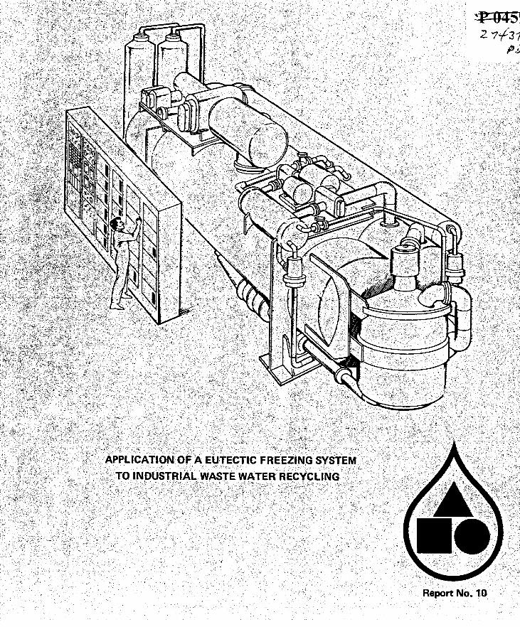
APPLICATION OF A EUTECTIC FREEZING SYSTEM
TO INDUSTRIAL WASTE WATER RECYCLING
Gerald Stepakoff Senior Staff Scientist
Presented at the
Industrial Waste Water Reuse Conference Environmental Section
American Institute of Chemical Engineers Washington, D.C.
David Siegelman Senior Staff Scientist
24April 1973
Avco Water Purification Program Avco Systems Division
Wilm ington, Massachusetts 0 1887

t
I
ABSTRACT
This paper presents an analysis of a two stage freeze concentration process which can be used to purify rinse waters from metal plating processes. The freezing unit employs much of the same technology as the Avco Crystalex Process. A description of the two stage freezer with eutectic separation of ice and dissolved solids is given together with mass and energy balances for the system operating in a closed water reuse loop in a metal plating plant. Preliminary estimates of the economic viability of the process are made on the basis of a model for weighting power, capital and labor costs. Results are normalized to the Crystalex Process operating a t 50% yield with sea water.
APPLICATION OF A EUTECTIC FREEZING SYSTEM TO INDUSTRIAL WASTE WATER RECYCLING
1. INTRODUCTION
During the last two decades, the waste loads imposed on natural waters from industrial waste water disposal have begun to exceed the natural ability of the receiving waters to assimilate the contaminants. Natural treatment such as sedimentation, sunlight and oxygen aeration has given way to chemical treatment, precipita- tion, ozonolysis, chlorination and physical processes such as ion exchange, activated charcoal adsorption, reverse osmosis and e1ectrodialysis.l From 1900 to 1960, the volume of municipal and industrial waste waters dis- charged into streams, lakes and other water sources in the United States increased by over 60%. In 1960 municipal waste volume discharges were estimated a t 22 billion gallons per day while industrial volumes were put a t 160 BGPD. By 1980 the present volumes are expected to double.
In contrast to the general uniformity of composi- tion in municipal waste waters, industrial waste waters show wide variations in composition, load and chemical content. Large quantities of industrial waste water can interfere with biological treatment processes as well as increase the total loads on such treatment facilities. Industrial waste waters are often more difficult to treat by conventional means because of heavy metals or non- biodegradable materials. Thus, industry has become more pressed to handle i ts wastes by various types of on site treatment facilities, by changes in process design to minimize waste water volumes, or by ground disposal in underground wells2 It is estimated that to achieve the water quality standards of municipal secondary treatment, it will require an investment of from 1.1 to 2.6 billion dollars to upgrade industrial waste treatment facilities and an additional 1.5 to 2.0 billion dollars to replace obsolete plants and install new treatment proce~ses.~
Industry i s now faced with the problem of achieving zero discharge by 1985 according to the recent Water
Quality Control Act. This has led to a renewed effort to develop water reuse systems for industrial processing. The purpose of this paper is to describe a conceptual design of a two-stage freezing process which can be used in conjunction with a water recycling system. The process is based on the Concentrex process, the patented trademark given to the direct contact eutectic freezing process under development by Avco Systems Division. In the following sections a summary is given of the principles of the eutectic freezing process along with a brief review of the salient results of bench scale testing of process compo- nents and feasibility studies. Then a process analysis is given of a closed loop metal plating waste-rinse system with the eutectic freezing unit supplying reclaimed fresh rinse water, makeup water for the plating tank and a concentrated slurry of plating tank chemicals for reuse in the plating process. Preliminary economics of the process are also presented.
I t . EUTECTIC FREEZING - CONCEPT DEFINITION
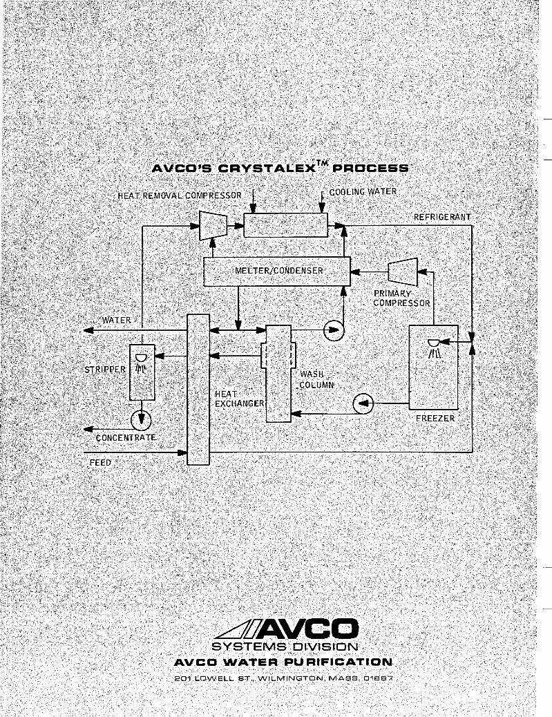
Eutectic freezing is a process in which concentrated brines are continuously frozen until the solution is saturated with respect to dissolved solids. Ice and precipi- tated solids are continuously removed from the system which is being fed by a raw waste stream. The freezing is carried out by direct contact heat transfer by evaporation of an immiscible refrigerant from the waste water in a closed vessel4 The eutectic freezing process is operated a t the eutectic temperature of the concentrated brine, the lowest temperature a t which ice and dissolved solids and waste brine can coexist. The Avco eutectic freezing process incorporates this basic physical principle into a continuous process which uses much of the technical and engineering achievements of the Avco secondary re- frigerant CRYSTALEXTM process for freeze desalination of sea water and brackish waters5 The process features the use of freon refrigerants (nonflammable and non-
toxic), direct contact heat transfer, stirred tank or spray freezers, cyclone separators and a pressurized counter- washer.
40-
The eutectic freezing process has application to both brackish water and industrial waste water treatment. In the case of brackish waters, many inland desalting plants operate so as to recover from 50 to 80% of the feed water as fresh water. However, a concentrated waste brine stream is also produced along with the product water and the volume of this waste may comprise 20% to 50% of the feed volume flow. This presents a formidable disposal problem. For the latter case, many industrial wastes contain dissolved solids which have economic value if recovered and returned to the main process. Also, in many cases, the waste waters cannot be disposed of because of the toxicity of the dissolved chemicals. Eutectic freezing or two-stage freeze concentration can be incorporated in such cases into a recycling process for water reuse of industrial and chemical wastes.
I SOLID NaCl i-
SOLUTION
I
A
I I 32.3OF
There are several general advantages of freezing for purifying waste water as well as specific advantages of the eutectic freezing process for recovery of dissolved solids. In general, freezing processes have a low specific energy requirement. For example, with a 3.5% saline sea water feed the specific energy is about 45 to 50 kwhr/l000 gal of product for a 1 mgpd plant6 Freezing processes based on a secondary refrigerant process have low capital cost and there is virtually no corrosion because of the low temperatures. The freezing process i s also nearly universal in that there are no restrictions on the feed composition or chemical makeup of the waste water. Eutectic freezing, which is the companion process to the secondary re- frigerant process, has the advantage of achieving very high concentration factors with a large reduction in waste volume. In many cases it is possible to produce a solid waste which is easier to dispose of than a liquid. The process can recover valuable solids without corrosion. It has lower power consumption than evaporation. There are no geological handicaps as with deep well disposal and no climatic restrictions or large land area requirements as with solar evaporation. Finally eutectic freezing plants can be used in conjunction with waste brine from any type of primary processing plant, R.0, ED, evaporation or freez- ing.
111. THERMODYNAMIC PRINCIPLE OF EUTECTIC FREEZING
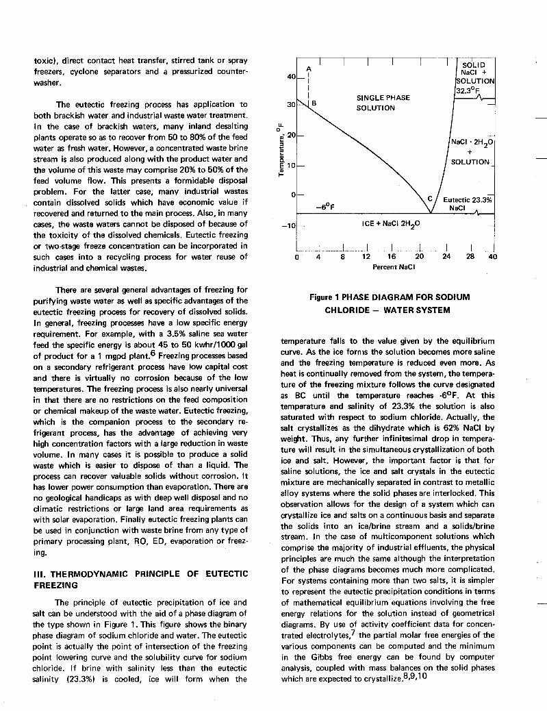
The principle of eutectic precipitation of ice and salt can be understood with the aid of a phase diagram of the type shown in Figure 1. This figure shows the binary phase diagram of sodium chloride and water. The eutectic point is actually the point of intersection of the freezing point lowering curve and the solubility curve for sodium chloride. I f brine with salinity less than the eutectic salinity (23.3%) is cooled, ice will form when the
I
- l o t
ICE + NaCl 2H20 i J
0 4 8 12 16 20 24 28 40 Percent NaCl
Figure 1 PHASE DIAGRAM FOR SODIUM CHLORIDE - WATER SYSTEM
temperature falls to the value given by the equilibrium curve. As the ice fornis the solution becomes more saline and the freezing temperature is reduced even more. As heat is continually removed from the system, the tempera- ture of the freezing mixture follows the curve designated as BC until the temperature reaches -6OF. At this temperature and salinity of 23.3% the solution is also saturated with respect to sodium chloride. Actually, the salt crystallizes as the dihydrate which is 62% NaCl by weight. Thus, any further infinitesimal drop in tempera- ture will result in the simultaneous crystallization of both ice and salt. However, the important factor is that for saline solutions, the ice and salt crystals in the eutectic mixture are mechanically separated in contrast to metallic alloy systems where the solid phases are interlocked. This observation allows for the design of a system which can crystallize ice and salts on a continuous basis and separate the solids into an ice/brine stream and a soliddbrine stream. In the case of multicomponent solutions which comprise the majority of industrial effluents, the physical principles are much the same although the interpretation of the phase diagrams becomes much more complicated. For systems containing more than two salts, it is simpler to represent the eutectic precipitation conditions in terms of mathematical equilibrium equations involving the free energy relations for the solution instead of geometrical diagrams. By use of activity coefficient data for concen- trated electrolytes? the partial molar free energies of the various components can be computed and the minimum in the Gibbs free energy can be found by computer analysis, coupled with mass balances on the solid phases which are expected to ~ r y s t a l l i z e . 8 ~ ~ ~ ~
IV. REVIEW OF BENCH SCALE TESTS
In order to assess the practical problems which might be encountered in a eutectic freezing process, Avco Systems Division conducted an investigation of the feasibility of unit operations of a eutectic freezing process. The details of the study are given in Reference 11. Here we l is t the significant results of the study. In summary the bench scale test loop established that:
1.
2.
3.
4.
5.
Ice and salts can be grown and nucleated as mechanically separate phases in a stirred tank freezer with direct contact heat transfer, under steady state conditions.
Ice can be separated from salt in flowing slurries with hydrocyclones with high eff i- ciencies.
Eutectic slurries of common inorganic salts can be pumped and otherwise handled in conventional plastic piping and slurry pumps without freeze-up, abrasion or clumping.
Eutectic ice crystals are of sufficient size and shape to allow washing in a countercurrent type wash column.
Practical operating conditions for most types of inorganic salts are a t temperatures of -1 O°F or above.
In addition to these studies, a mobile demonstration lab was designed and constructed which has two stage eutectic freezing capability. It i s expected that the mobile lab unit will be ready for field testing by the summer of 1973.
V. PROCESS DESCRIPTION
The eutectic freezing process for waste water recycling is a two stage process. The use of staging has several significant advantages over a single stage system. In the latter case, a low salinity brine (typically less than 5% TDS) is concentrated to the eutectic point in one step. This requires much more compressor work than the two stage process. The compressor work (the work done in compressing the evaporated refrigerant) comprises the major power cost element of the process (along with some pump work required to pump the ice slurry through the wash column and cyclones). By staging the process a major fraction of the refrigerant vapor is compressed from an elevated pressure because of the relatively high freezing temperature in the first stage. Thus, the compressor work is reduced by a significant amount.
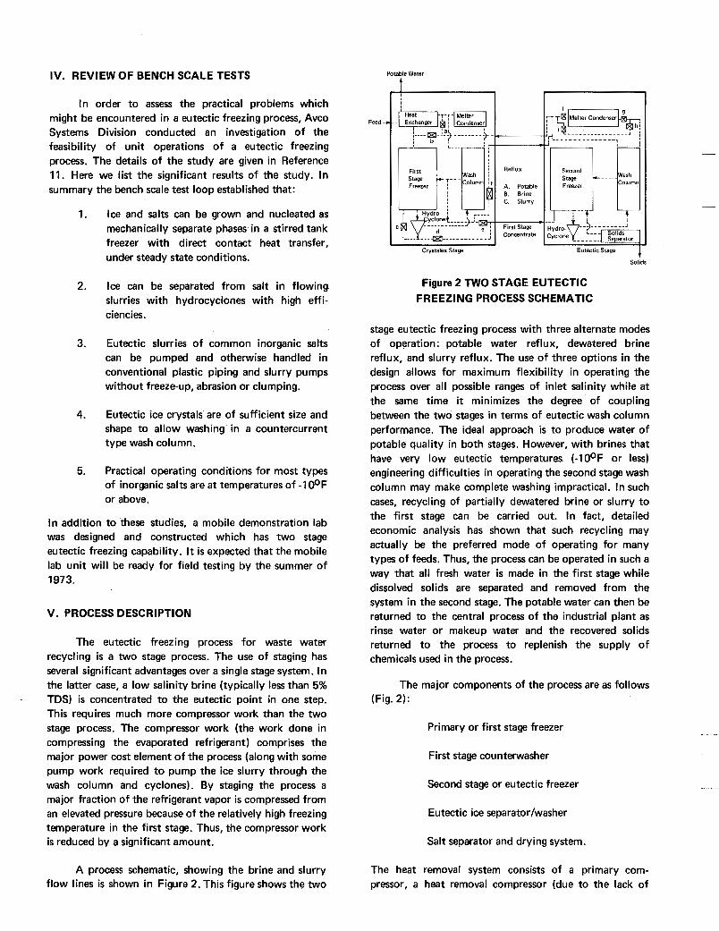
A process schematic, showing the brine and slurry flow lines is shown in Figure 2. This figure shows the two
Feed -
Potable Water
I
Solids
Figure 2 TWO STAGE EUTECTIC FREEZING PROCESS SCHEMATIC
stage eutectic freezing process with three alternate modes of operation: potable water reflux, dewatered brine reflux, and slurry reflux. The use of three options in the design allows for maximum flexibility in operating the process over all possible ranges of inlet salinity while a t the same time it minimizes the degree of coupling between the two stages in terms of eutectic wash column performance. The ideal approach is to produce water of potable quality in both stages. However, with brines that have very low eutectic temperatures (-10°F or less) engineering difficulties in operating the second stage wash column may make complete washing impractical. In such cases, recycling of partially dewatered brine or slurry to the first stage can be carried out. In fact, detailed economic analysis has shown that such recycling may actually be the preferred mode of operating for many types of feeds. Thus, the process can be operated in such a way that all fresh water is made in the first stage while dissolved solids are separated and removed from the system in the second stage. The potable water can then be returned to the central process of the industrial plant as rinse water or makeup water and the recovered solids returned to the process to replenish the supply of chemicals used in the process.
The major components of the process are as follows (Fig. 2):
Primary or first stage freezer
First stage counterwasher
Second stage or eutectic freezer
Eutectic ice separatorlwasher
Salt separator and drying system.
The heat removal system consists of a primary com- pressor, a heat removal compressor (due to the lack of
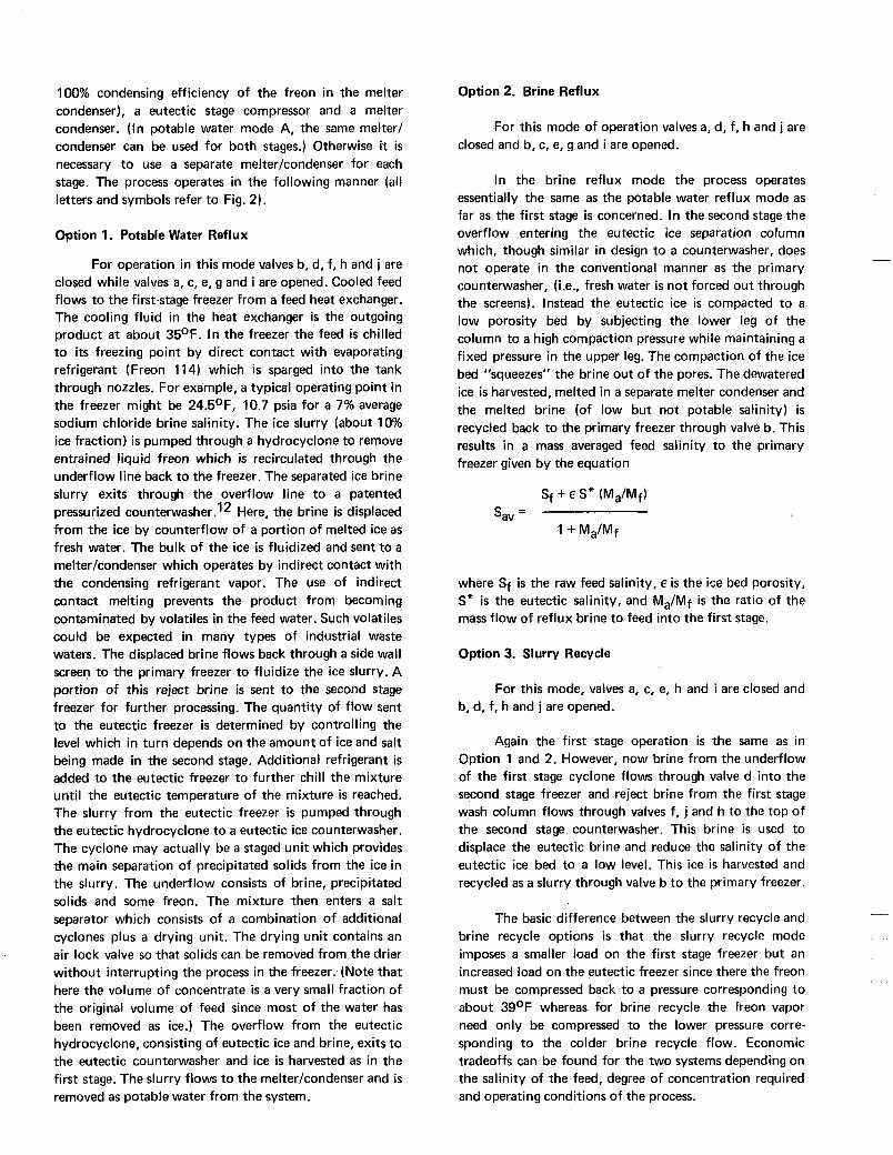
100% condensing efficiency of the freon in the melter condenser), a eutectic stage compressor and a melter condenser. (In potable water mode A, the same melter/ condenser can be used for both stages.) Otherwise it is necessary to use a separate melter/condenser for each stage. The process operates in the following manner (all letters and symbols refer to Fig. 2).
Option 1. Potable Water Reflux
For operation in this mode valves b, d, f, h and j are closed while valves a, c, e, g and i are opened. Cooled feed flows to the first-stage freezer from a feed heat exchanger. The cooling fluid in the heat exchanger is the outgoing product a t about 35OF. In the freezer the feed is chilled to i ts freezing point by direct contact with evaporating refrigerant (Freon 114) which is sparged into the tank through nozzles. For example, a typical operating point in the freezer might be 24.5OF, 10.7 psia for a 7% average sodium chloride brine salinity. The ice slurry (about 10% ice fraction) is pumped through a hydrocyclone to remove entrained liquid freon which is recirculated through the underflow line back to the freezer. The separated ice brine slurry exits through the overflow line to a patented pressurized c0unterwasher.l Here, the brine is displaced from the ice by counterflow of a portion of melted ice as fresh water. The bulk of the ice is fluidized and sent to a melter/condenser which operates by indirect contact with the condensing refrigerant vapor. The use of indirect contact melting prevents the product from becoming contaminated by volatiles in the feed water. Such volatiles could be expected in many types of industrial waste waters. The displaced brine flows back through a side wall screen to the primary freezer to fluidize the ice slurry. A portion of this reject brine is sent to the second stage freezer for further processing. The quantity of flow sent to the eutectic freezer is determined by controlling the level which in turn depends on the amount of ice and salt being made in the second stage. Additional refrigerant is added to the eutectic freezer to further chill the mixture until the eutectic temperature of the mixture i s reached. The slurry from the eutectic freezer is pumped through the eutectic hydrocyclone to a eutectic ice counterwasher. The cyclone may actually be a staged unit which provides the main separation of precipitated solids from the ice in the slurry. The underflow consists of brine, precipitated solids and some freon. The mixture then enters a salt separator which consists of a combination of additional cyclones plus a drying unit. The drying unit contains an air lock valve so that solids can be removed from the drier without interrupting the process in the freezer. (Note that here the volume of concentrate is a very small fraction of the original volume of feed since most of the water has been removed as ice.) The overflow from the eutectic hydrocyclone, consisting of eutectic ice and brine, exits to the eutectic counterwasher and ice is harvested as in the first stage. The slurry flows to the melter/condenser and is removed as potable water from the system.
Option 2. Brine Reflux
For this mode of operation valves a, d, f, h and j are closed and b, c, e, g and i are opened.
In the brine reflux mode the process operates essentially the same as the potable water reflux mode as far as the first stage is concerned. In the second stage the overflow entering the eutectic ice separation column which, though similar in design to a counterwasher, does not operate in the conventional manner as the primary counterwasher, (i.e., fresh water is not forced out through the screens). Instead the eutectic ice is compacted to a low porosity bed by subjecting the lower leg of the column to a high compaction pressure while maintaining a fixed pressure in the upper leg. The compaction of the ice bed "squeezes" the brine out of the pores. The dewatered ice is harvested, melted in a separate melter condenser and the melted brine (of low but not potable salinity) is recycled back to the primary freezer through valve b. This results in a mass averaged feed salinity to the primary freezer given by the equation
where Sf i s the raw feed salinity, e is the ice bed porosity, S" is the eutectic salinity, and Ma/Mf is the ratio of the mass flow of reflux brine to feed into the first stage.
Option 3. Slurry Recycle
For this mode, valves a, c, e, h and i are closed and b, d, f, h and j are opened.
Again the first stage operation is the same as in Option 1 and 2. However, now brine from the underflow of the first stage cyclone flows through valve d into the second stage freezer and reject brine from the first stage wash column flows through valves f, j and h to the top of the second stage counterwasher. This brine is used to displace the eutectic brine and reduce the salinity of the eutectic ice bed to a low level. This ice is harvested and recycled as a slurry through valve b to the primary freezer.
The basic difference between the slurry recycle and brine recycle options is that the slurry recycle mode imposes a smaller load on the first stage freezer but an increased load on the eutectic freezer since there the freon must be compressed back to a pressure corresponding to about 39OF whereas for brine recycle the freon vapor need only be compressed to the lower pressure corre- sponding to the colder brine recycle flow. Economic tradeoffs can be found for the two systems depending on the salinity of the feed, degree of concentration required and operating conditions of the process.
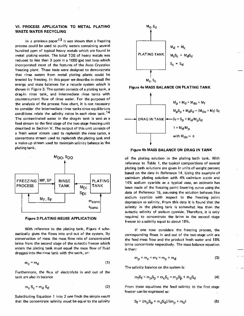
VI. PROCESS APPLICATION TO METAL PLATING WASTE WATER RECYCLING
In a previous paper13 it was shown that a freezing process could be used to purify waters containing several hundred ppm of typical heavy metals which are found in metal plating wastes. The total TDS of heavy metals was reduced to less than 2 ppm in a 1000 gpd test loop which incorporated most of the features of the Avco Crystalex freezing plant. These tests were designed to demonstrate that rinse waters from metal plating plants could be treated by freezing. In this paper we describe in detail the energy and mass balances for a recycle system which is shown in Figure 3. The system consists of a plating tank, a drag-in rinse tank, and intermediate rinse tanks with countercurrent flow of rinse water. For the purposes of the analysis of the process flow chart, it is not necessary to consider the intermediate rinse tanks since equilibrium conditions relate the salinity ratios in each rinse tank.14 The contaminated water in the dragin tank is sent as a feed stream to the first stage of the two-stage freezing unit described in Section V. The output of this unit consists of a fresh water stream used to replenish the rinse tanks, a concentrate stream used to replenish the plating tank and a make-up stream used to maintain salinity balance in the plating tank.
F R EEZl NG PROCESS
MDOp sDO
Sconc I I Figure 3 PLATING REUSE APPLICATION
With reference to the plating tank, Figure 4 sche- matically gives the flows into and out of the system. By conservation of mass the mass flow rate of concentrated brine from the second stage of the eutectic freezer which enters the plating tank must equal the mass flow of fluid dragged into the rinse tank with the work, or:
mc = md (1 1
Furthermore, the flux of electrolyte in and out of the tank are also in balance
Substituting Equation 1 into 2 one finds the simple result that the concentrate salinity must be equal to the salinity
Mde sd
t PLATING TANK
t Mc. sc
Figure 4a MASS BALANCE ON PLATING TANK
Figure 4b MASS BALANCE ON DRAG IN TANK
of the plating solution in the plating bath tank. With reference to Table 1, the typical compositions of several plating bath solutions are given in units of weight percent based on the data in Reference 14. Using the example of cadmium plating solution with 4% cadmium oxide and 14% sodium cyanide as a typical case, an estimate has been made of the freezing point lowering curve using the data of Reference 15, assuming the solution behaves like sodium cyanide with respect to the freezing point depression vs salinity. From this data it i s found that the salinity in the plating tank is somewhat less than the eutectic salinity of sodium cyanide. Therefore, it is only required to concentrate the brine in the second stage freezer to a salinity equal to about 18%.
I f one now considers the freezing process, the corresponding flows in and out of the two-stage unit are the feed mass flow and the product fresh water and 18% brine concentrate respectively. The mass balance equation is then :
m P +mc=mf=mp+md (3)
The salinity balance on the system is:
mfSf = mpSp + mcSc = mpS,-, + mdsd (4)
From these equations the feed salinity to the first stage freezer can be expressed as:
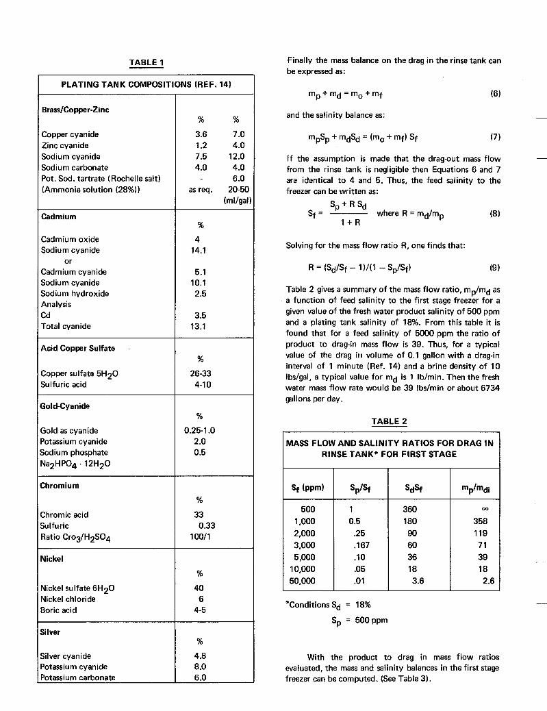
TABLE 1
60 36 18 3.6
I PLATING TANK COMPOSITIONS (REF. 14)
71 39 18 2.6
Brass/Copper-Zinc
Copper cyanide Zinc cyanide Sodium cyanide Sodium carbonate Pot. Sod. tartrate (Rochelle sal t ) (Ammonia solution (28%))
Cadmium
Cadmium oxide Sodium cyanide
or Cadmium cyanide Sodium cyanide Sodium hydroxide Analysis Cd Total cyanide
Acid Copper Sulfate
Copper sulfate 5H20 Sulfuric acid
Gold-Cyanide
Gold as cyanide Potassium cyanide Sodium phosphate Na2HP04 - 12H20
Chromium
Chromic acid Sulfuric Ratio Crog/H2SOq
Nickel
Nickel sulfate 6H2O Nickel chloride Boric acid
Silver
Silver cyanide Potassium cyanide Potassium carbonate
% %
3.6 7 .O 1.2 4 .O 7.5 12.0 4 .O 4 .O
6 .O as req. 20-50
(ml/gal~
%
4 14.1
5.1 10.1 2.5
3.5 13.1
%
26-33 4-1 0
%
0.25-1 .O 2 .o 0.5
%
33
100/1 0.33
%
40 6
4-5
%
4.8 8 .o 6.0
Finally the mass balance on the drag in the rinse tank can be expressed as:
(6) m + m d = m o + m f P
and the salinity balance as:
I f the assumption is made that the drag-out mass flow from the rinse tank is negligible then Equations 6 and 7 are identical to 4 and 5. Thus, the feed salinity to the freezer can be written as:
Sp + R sd Sf = where R = md/mp (8 1
l + R
Solving for the mass flow ratio R, one finds that:
Table 2 gives a summary of the mass flow ratio, mp/md as a function of feed salinity to the first stage freezer for a given value of the fresh water product salinity of 500 ppm and a plating tank salinity of 18%. From this table it is found that for a feed salinity of 5000 ppm the ratio of product to dragin mass flow is 39. Thus, for a typical value of the drag i t 1 volume of 0.1 gallon with a drag-in interval of 1 minute (Ref. 14) and a brine density of 10 Ibs/gal, a typical value for md is 1 Ib/min. Then the fresh water mass flow rate would be 39 Ibs/min or about 6734 gallons per day.
TABLE 2
MASS FLOW AND SALINITY RATIOS FOR DRAG IN RINSE TANK* FOR FIRST STAGE
500 1,000 2,000 3,000 5,000
10,000 50,000
1 0.5
.25
.I67
.10
.05
.o 1
360 180 90
35; I 119
"ConditionsSd = 18%
Sp = 500ppm
With the product to drag in mass flow ratios evaluated, the mass and salinity balances in the first stage freezer can be computed. (See Table 3).
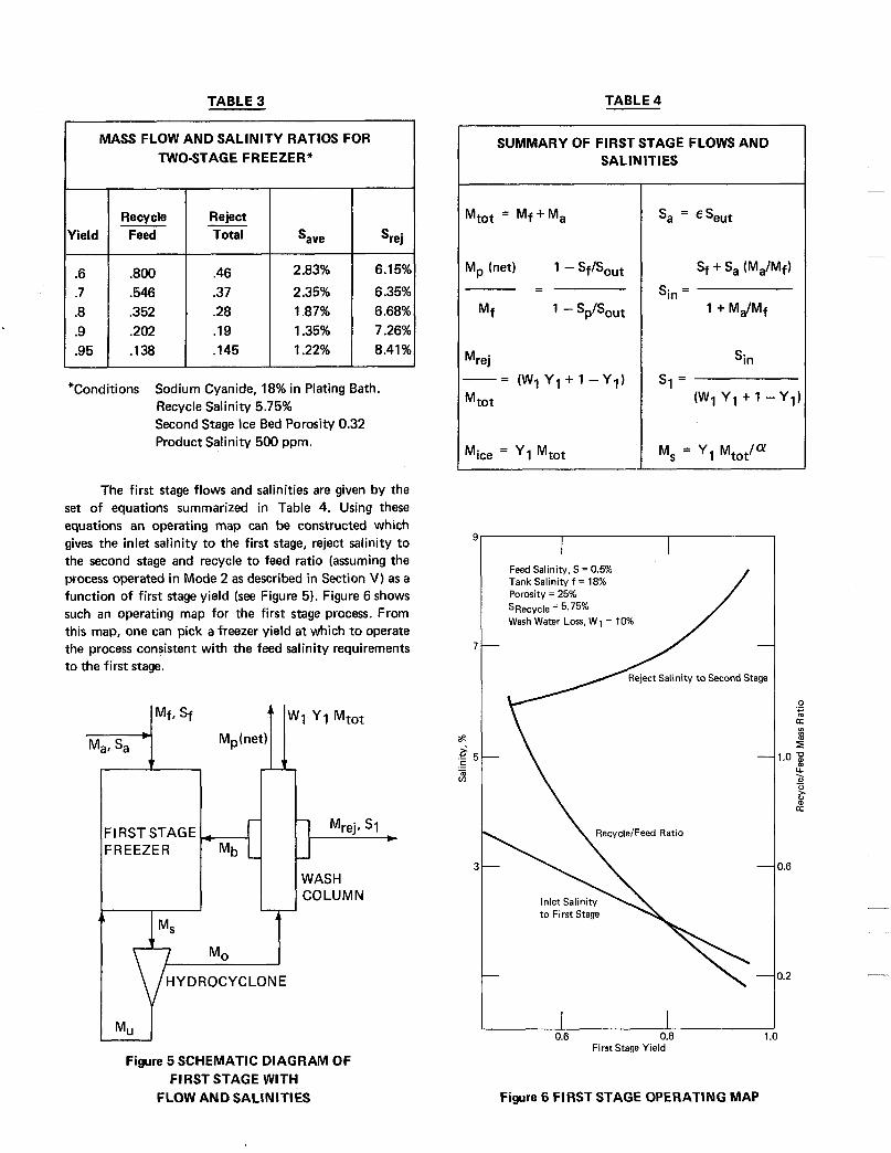
TABLE 3
MASS FLOW AND SALINITY RATIOS FOR TWOSTAGE FREEZER*
.46
.37
.28
.I9
.I45
Recycle
.202 .95 .I38
2.83% 6.15%
2.35% 6.35% 1.87% 6.68% 1.35% 7.26% 1.22% 8.41%
Reject Total
- Mrejl SI
- WASH COLUMN
*Conditions Sodium Cyanide, 18% in Plating Bath. Recycle Salinity 5.75% Second Stage Ice Bed Porosity 0.32 Product Salinity 500 pprn.
The first stage flows and salinities are given by the set of equations summarized in Table 4. Using these equations an operating map can be constructed which gives the inlet salinity to the first stage, reject salinity t o the second stage and recycle t o feed ratio (assuming the process operated in Mode 2 as described in Section V) as a function o f first stage yield (see Figure 5). Figure 6 shows such an operating map for the first stage process. From this map, one can pick a freezer yield a t which to operate the process consistent wi th the feed salinity requirements t o the first stage.
F I RST STAG E FREEZER i I 4
Mp(net) t Iw1 y1 Mtot
d
HYDROCYCLONE r Figure 5 SCHEMATIC DIAGRAM OF
FIRST STAGE WITH FLOW AND SALINITIES
TABLE 4
SUMMARY OF FIRST STAGE FLOWS AND SALINITIES
Mice = YI Mtot
Sin
(W1 Y1+ 1 -y1: S I =
Feed Salinity, S = 0.5% Tank Salinity f = 18% Porosity = 25%
Wash Water Loss, W1 = 10% SRe,-y& = 5.75%
-
- \
1 .o 1
0.6 0.8 First Stage Yield
Figure 6 FIRST STAGE OPERATING MAP
0 ._ +- a VI
s .o p
; U . -
2
1.6
1.2
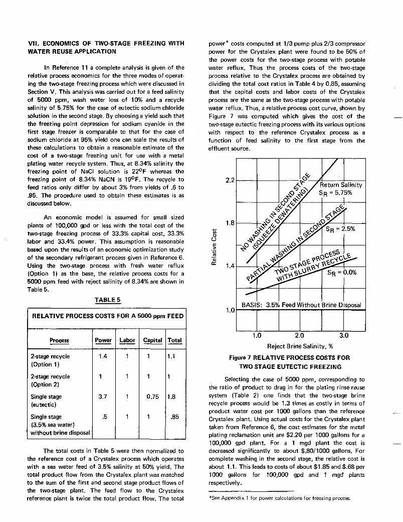
VII. ECONOMICS OF TWO-STAGE FREEZING WITH WATER REUSE APPLICATION
In Reference 1 1 a complete analysis is given of the relative process economics for the three modes of operat- ing the two-stage freezing process which were discussed in Section V. This analysis was carried out for a feed salinity of 5000 ppm, wash water loss of 10% and a recycle salinity of 5.75% for the case of eutectic sodium chloride solution in the second stage. By choosing a yield such that the freezing point depression for sodium cyanide in the first stage freezer is comparable to that for the case of sodium chloride a t 95% yield one can scale the results of these calculations to obtain a reasonable estimate of the cost of a two-stage freezing unit for use with a metal plating water recycle system. Thus, at 8.34% salinity the freezing point of NaCl solution is 22OF whereas the freezing point of 8.34% NaCN is 19OF. The recycle to feed ratios only differ by about 3% from yields of .6 to .95. The procedure used to obtain these estimates is as discussed below.
An economic model is assumed for small sized plants of 100,000 gpd or less with the total cost of the two-stage freezing process of 33.3% capital cost, 33.3% labor and 33.4% power. This assumption is reasonable based upon the results of an economic optimization study of the secondary refrigerant process given in Reference 6. Using the twostage process with fresh water reflux (Option 1) as the base, the relative process costs for a 5000 ppm feed with reject salinity of 8.34% are shown in Table 5.
TABLE 5
RELATIVE PROCESS COSTS FOR A 5000 ppm FEED
Process
2-stage recycle (Option 1)
2-stage recycle (Option 2)
Single stage (eutectic )
Single stage (3.5% sea water) without brine disposal
P x r
1.4
1
3.7
.5
Labor Capital - 1
1
0.75
1
1 . I
1
1.8
.85
- The total costs in Table 5 were then normalized to
the reference cost of a Crystalex process which operates with a sea water feed of 3.5% salinity a t 50% yield. The total product flow from the Crystalex plant was matched to the sum of the first and second stage product flows of the two-stage plant. The feed flow to the Crystalex reference plant is twice the total product flow. The total
power* costs computed a t 113 pump plus 213 compressor power for the Crystalex plant were found to be 50% of the power costs for the two-stage process with potable water reflux. Thus the process costs of the two-stage process relative to the Crystalex process are obtained by dividing the total cost ratios in Table 4 by 0.85, assuming that the capital costs and labor costs of the Crystalex process are the same as the two-stage process with potable water reflux. Thus, a relative process cost curve, shown by Figure 7 was computed which gives the cost of the two-stage eutectic freezing process with i ts various options with respect to the reference Crystalex process as a function of feed salinity to the first stage from the effluent source.
2.2
1.8 + 8 u al > +.’ m Q)
.- -
1.4
1 .o 2.0 3.0 Reject Brine Salinity, %
Figure 7 RELATIVE PROCESS COSTS FOR TWO STAGE EUTECTIC FREEZING
Selecting the case of 5000 ppm, corresponding to the ratio of product to drag in for the plating rinse reuse system (Table 2) one finds that the two-stage brine recycle process would be 1.3 times as costly in terms of product water cost per 1000 gallons than the reference Crystalex plant, Using actual costs for the Crystalex plant taken from Reference 6, the cost estimates for the metal plating reclamation unit are $2.20 per 1000 gallons for a 100,000 gpd plant. For a 1 mgd plant the cost is decreased significantly to about $.80/1000 gallons. For complete washing in the second stage, the relative cost is about 1 .I. This leads to costs of about $1.85 and $.68 per 1000 gallons for 100,000 gpd and 1 mgd plants respectively.
*See Appendix 1 for power calculations for freezing process.
APPENDIX 1
RELATIVE POWER REQUIREMENTS FOR A TWO STAGE VERSUS SINGLE
STAGE PROCESS
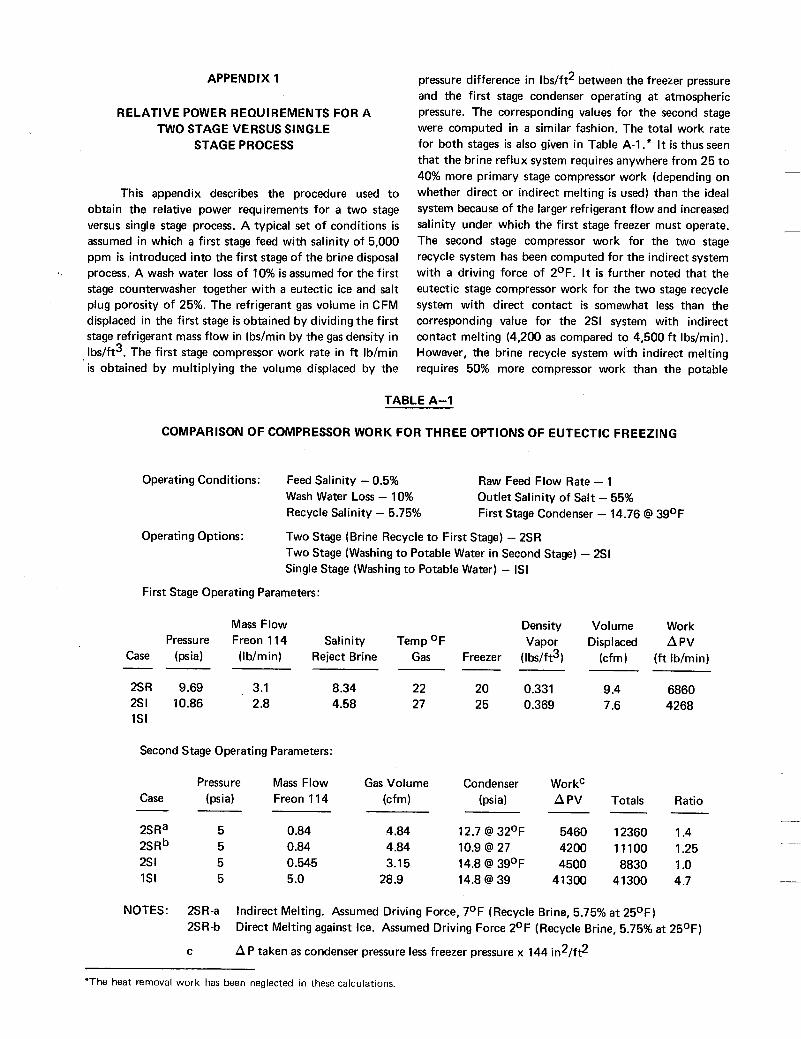
This appendix describes the procedure used to obtain the relative power requirements for a two stage versus single stage process. A typical set of conditions is assumed in which a first stage feed with salinity of 5,000 ppm is introduced into the first stage of the brine disposal process. A wash water loss of 10% is assumed for the first stage counterwasher together with a eutectic ice and salt plug porosity of 25%. The refrigerant gas volume in CFM displaced in the first stage is obtained by dividing the first stage refrigerant mass flow in Ibs/min by the gas density in Ibs/ft3. The first stage compressor work rate in f t Ib/min is obtained by multiplying the volume displaced by the
'
pressure difference in Ibs/ft2 between the freezer pressure and the first stage condenser operating at atmospheric pressure. The corresponding values for the second stage were computed in a similar fashion. The total work rate for both stages is also given in Table A-I .* It is thus seen that the brine reflux system requires anywhere from 25 to 40% more primary stage compressor work (depending on whether direct or indirect melting is used) than the ideal system because of the larger refrigerant flow and increased salinity under which the first stage freezer must operate. The second stage compressor work for the two stage recycle system has been computed for the indirect system with a driving force of 2OF. It is further noted that the eutectic stage compressor work for the two stage recycle system with direct contact is somewhat less than the corresponding value fQr the 2SI system with indirect contact melting (4,200 as compared to 4,500 f t Ibs/min). However, the brine recycle system with indirect melting requires 50% more compressor work than the potable
TABLE A-I
COMPARISON OF COMPRESSOR WORK FOR THREE OPTIONS OF EUTECTIC FREEZING
Operating Conditions: Feed Salinity - 0.5% Wash Water Loss - 10% Recycle Salinity - 5.75%
Two Stage (Brine Recycle to First Stage) - 2SR Two Stage (Washing to Potable Water in Second Stage) - 2SI Single Stage (Washing to Potable Water) - IS1
Raw Feed Flow Rate - 1 Outlet Salinity of Salt - 55% First Stage Condenser - 14.76 @ 39OF
Operating Options:
First Stage Operating Parameters:
Mass Flow Density Volume Work Pressure Freon 114 Salinity Temp OF Vapor Displaced APV
Case (psia) (Ib/min) Reject Brine Gas Freezer ( Ibs/ft3) (cfm) (f t Ib/min) --- -- 2SR 9.69 3.1 8.34 22 20 0.331 9.4 6860 2SI 10.86 2.8 4.58 27 25 0.369 7.6 4268 IS1
Second Stage Operating Parameters:
Pressure Mass Flow Gas Volume Condenser WorkC (psis) Freon 114 (cfm) (psis) APV Totals Ratio Case
2SRa 5 0.84 4.84 12.7 @ 32OF 5460 12360 1.4 2SRb 5 0.84 4.84 10.9 @ 27 4200 11100 1.25 2s I 5 0.545 3.15 14.8 @ 39OF 4500 8830 1.0 IS1 5 5 .O 28.9 14.8 @ 39 41300 41300 4.7
- - -
NOTES: 2SR-a 2SR-b
C
Indirect Melting. Assumed Driving Force, 7OF (Recycle Brine, 5.75% a t 25OF) Direct Melting against Ice. Assumed Driving Force 2OF (Recycle Brine, 5.75% at 25OF)
A P taken as condenser pressure less freezer pressure x 144 in2/ft2
*The heat removal work has been neglected in these calculations.
reflux system. Note that the compressor work for the single stage system is almost an order of magnitude larger than the two stage system. This is due to the necessity of operating the single stage process with much larger refrigerant mass flow rates and lower temperatures and pressures.
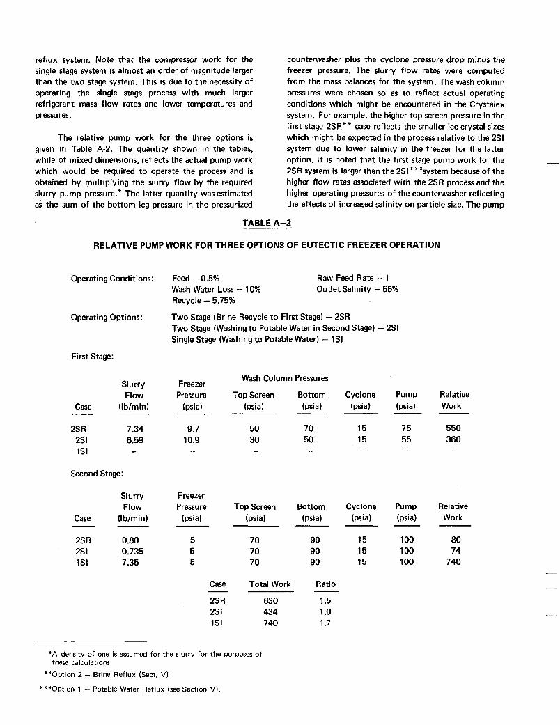
The relative pump work for the three options is given in Table A-2. The quantity shown in the tables, while of mixed dimensions, reflects the actual pump work which would be required to operate the process and is obtained by multiplying the slurry flow by the required slurry pump pressure.* The latter quantity was estimated as the sum of the bottom leg pressure in the pressurized
counterwasher plus the cyclone pressure drop minus the freezer pressure. The slurry flow rates were computed from the mass balances for the system. The wash column pressures were chosen so as to reflect actual operating conditions which might be encountered in the Crystalex system. For example, the higher top screen pressure in the first stage 2SR** case reflects the smaller ice crystal sizes which might be expected in the process relative to the 2SI system due to lower salinity in the freezer for the latter option. It is noted that the first stage pump work for the 2SR system is larger than the 2Sl***system because of the higher flow rates associated with the 2SR process and the higher operating pressures of the counterwasher reflecting the effects of increased salinity on particle size. The pump
TABLE A-2
RELATIVE PUMP WORK FOR THREE OPTIONS OF EUTECTIC FREEZER OPERATION
Operating Conditions :
Operating Options:
First Stage:
Slurry Flow
Case (Ib/min) - 2s R 7.34 2s I 6.59 1SI -_
Second Stage:
Slurry Flow
Case (I b/min)
2s R 0.80 2s I 0.735 1SI 7.35
Feed - 0.5% Wash Water Loss - 10% Recycle - 5.75%
Two Stage (Brine Recycle to First Stage) - 2SR Two Stage (Washing to Potable Water in Second Stage) - 2SI Single Stage (Washing to Potable Water) - 1SI
Raw Feed Rate - 1 Outlet Salinity - 55%
Wash Column Pressures Freezer Pressure Top Screen Bottom
(psia) (psis) (psis)
9.7 50 70 10.9 30 50
_ _ _ _ --
Freezer Pressure Top Screen Bottom
(psia) (psia) (psia)
5 70 5 70 5 70
Case Total Work
2s R 630 2s I 434 1SI 740
-
90 90 90
Ratio
1.5 1 .o 1.7
Cyclone (psis)
15 15 _ _
Cyclone (psis)
15 15 15
Pump (psis)
75 55 _ _
Pump (psis)
100 1 00 100
Relative Work
550 360 _ _
Relative Work
80 74
740
*A density of one is assumed for the slurry for the purposes o f these calculations.
**Option 2 - Brine Reflux (Sect. V)
***Option 1 - Potable Water Reflux (see Section VI.
work for the eutectic stage was based on the assumption that the salt hydrate can be dewatered in a separation column to a salinity of 55%. The result is that the relative pump work is about 50% less for the 2SI system as compared to the 2SR case and 70% less than the ISS case. *
In order to convert these relative power require- ments into a relative process cost, it is necessary to make some assumptions concerning the ratio of power costs to the other factors which affect total plant cost. I f one assumes that the costs are equally distributed among power, capital investment and labor, and that the com- pressor work comprises 67% of the power costs, with 33% due to pump work, the relative costs are obtained as given in Table 5 of Section VII. Using this model, then, one finds that the two stage recycle system would only cost
10% more than the ideal system with potable washing. When one considers the engineering development required to achieve a practical system which could produce potable water from eutectic ice, it can be concluded that the development of the two stage recycle system may actually turn out to be the more economical process for the immediate future.
ACKNOWLEDGMENT
The authors wish to acknowledge the partial sup- port of this work under OSW Contract 14-30-2945 to Avco Systems Division, Water Purification Program Office. Thanks are due to Mr. J. Fraser, Program Manager, for useful discussions on the economics of freezing processes.
*Single stage.
REFER E NCES
1.
2.
3.
4.
5.
6.
7.
8.
9.
IO.
11.
"McGraw-Hill Encyclopedia of Science and Technology," McGraw-Hill, 74,454 (1971).
"Harper Encyclopedia of Science," Harper and Row, N.Y ., 1239.
"Cleaning Our Environment, The Chemical Basis for Action," American Chemical Society Special Report, 1 38, (1 969).
Barduhn, A. J., "The Freezing Process for Water Conversion in the United States," Selected Papers on Desalination and Ocean Technology, S. N. Levine, ed., Dover, New York, N.Y., 414, (1968).
Fraser, J. M. and W. E. Gibson, "A New Look a t Secondary Refrigerant Desa I i na t i on ," Xllth International Congress of Re- frigeration, Washington, D.C., August 30, 1971.
Fraser, J. H. and T. A. Olsson, "Final Report on Economic Optimization of the Avco Crystallization Process," AVSD- 0242-72-RR, June 29, 1972, Avco Systems Division, Wilmington, Mass.
Akerlof, G., "A Study of the Composition of the Liquid Phase in Aqueous Systems Containing Strong Electrolytes of Higher Valence Types as Solid Phases,"J. Phys. Chem., 47, 1053 (1937).
Stumm, W. and J. J. Morgan, "Aquatic Chemistry," Wiley- Interscience (19701, Chaps. 2,6, and 8.
Zelenik, F. J. and S. Gordon, "Calculation of Complex Equi- libria," lndustrialand Eng. Chem., 60,27 (1968).
"Equilibrium Concepts in Natural Water Systems," Advances in Chemistry Series, No. 67, American Chemical Society, Washing- ton, D.C., 1967.
Stepakoff, G. L., D. Siegelman and R. Johnson, "Eutectic Freezing Process Investigations," AVSD-0089-73-R R, March 20, 1973, Avco Systems Division, Wilmington, Mass.
12. , Probstein, R. F. and J. Shwartz, "Method of Separating Solid Particles from a Slurry with a Wash Column Separator," U.S. Patent 3587859 (1971). See also, J. Shwartz and R. F. Probstein, "Experimental Study of Slurry Separators for Use in Desali- nation, " Desalination, 6, pp. 239-266 (1969).
13.
14.
15.
Campbell, R . J. and D. K. Emmermann, "Recycling of Water from Metal Finishing Wastes by Freezing Processes," Paper 72-PID-7. Presented a t Joint ASME/EPA Reuse and Treatment of Waste Water Symposium, New Orleans, La., March 28, 1972.
Graham, A. K., "Electroplating Engineering Handbook," 2nd ed., Reinhold, New York (1962), p, 229.
Seidell, A., "Solubilities of Inorganic and Metal Organic Com- pounds," 3rd ed., Vol. 1 (19531, p. 1189.

,