Embed Size (px)
Citation preview

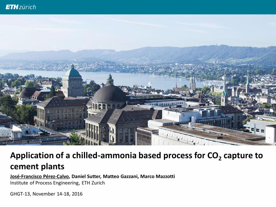
José-Francisco Pérez-Calvo, Daniel Sutter, Matteo Gazzani, Marco Mazzotti Institute of Process Engineering, ETH Zurich
GHGT-13, November 14-18, 2016
Application of a chilled ammonia-based process for CO2 capture to cement plants
| | Institute of Process Engineering 9-Dec-16 José-Francisco Pérez-Calvo, [email protected] 2
Talk outline
Introduction
The Chilled Ammonia Process (CAP)
Scope of the study
CAP model for simulations
Heuristic optimization approach and results
Conclusions
| | Institute of Process Engineering 9-Dec-16 José-Francisco Pérez-Calvo, [email protected] 3
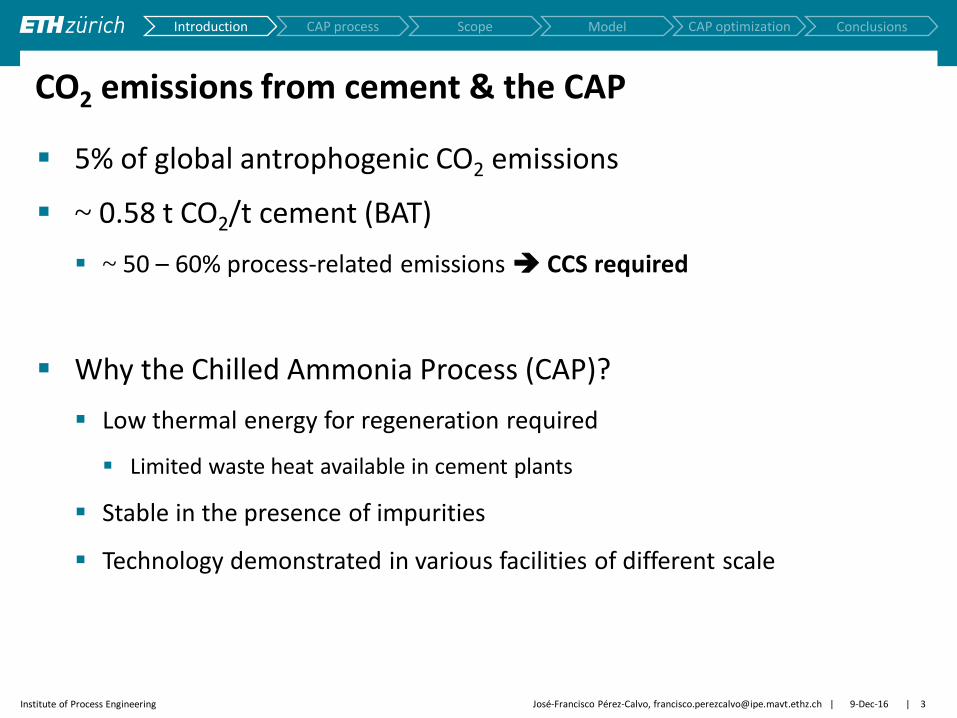
CO2 emissions from cement & the CAP
5% of global antrophogenic CO2 emissions
~ 0.58 t CO2/t cement (BAT)
~ 50 – 60% process-related emissions CCS required
Why the Chilled Ammonia Process (CAP)?
Low thermal energy for regeneration required
Limited waste heat available in cement plants
Stable in the presence of impurities
Technology demonstrated in various facilities of different scale
Scope Introduction CAP process Model CAP optimization Conclusions

| | Institute of Process Engineering 9-Dec-16 José-Francisco Pérez-Calvo, [email protected] 4
The Chilled Ammonia Process
Scope Introduction CAP process Model CAP optimization Conclusions

| | Institute of Process Engineering 9-Dec-16 José-Francisco Pérez-Calvo, [email protected] 5
From power plants to cement plants
NG power plants and
cracker
4 %vol. CO2
Coal-fired power plants
14 %vol. CO2
Cement plants
15 – 35%vol. CO2
Process complexity
Thermodynamics
Kinetics
Heat integration
Model-based
optimization
Higher L/G
Higher NH3 content
Lower CO2 loading
Combination
Adaptation of
operating conditions
Scope Introduction CAP process Model CAP optimization Conclusions

| | Institute of Process Engineering 9-Dec-16 José-Francisco Pérez-Calvo, [email protected] 6
Scope of the study Pilot plant tests
CSIRO
Rate-based model
(Aspen Plus)
Equilibrium-based
model (Aspen Plus)
Thomsen thermodynamic model[1,2]
Murphree effs. for power plants from literature[3,4]
0
Sta
rtin
g
po
int
Th
is w
ork
Literature research
Adaptation of kinetic parameters
1
Model validation 2
3
Model-based optimization
Computationally
intensive
Ad-hoc Murphree effs. for cement plants
Thomsen thermodynamic model[1,2]
4
[1] Thomsen and Rasmussen Chem Eng Sci 54 (1999) 1787-1802 [2] Darde et al. Ind Eng Chem Res 49 (2010) 12663-74
[3] Sutter et al. Faraday Discuss 192 (2016) 59-83 [4] Jilvero et al. Ind Eng Chem Res 53 (2014) 6750-6758
Scope Introduction CAP process Model CAP optimization Conclusions

| | Institute of Process Engineering 9-Dec-16 José-Francisco Pérez-Calvo, [email protected] 7
Thermodynamic model: CO2-NH3-H2O system
Vapor
Liquid
Solid
CO2 + H2O ↔ HCO3- + H+
HCO3- ↔ CO3
2- + H+ NH3 + H+ ↔NH4
+
NH3 + HCO3- ↔NH2COO- + H2O
CO2 H2O NH3
CO2 H2O NH3
(NH4)HCO3 (NH4)2CO3·2NH4HCO3
(NH4)2CO3·H2O NH2COONH4 Ice
[1] Darde et al. Ind Eng Chem Res 49 (2010) 12663-74 [2] Jänecke Z Elektrochem 35 (1929) 9:716-28
SRK for gas fugacities
Extended UNIQUAC (Thomsen-Darde[1])
Solubility data for solids fitted on Jänecke[2]
Pure solids, activity = 1
VLE
SLE
External routine in Aspen
from Thomsen group
Thomsen model to predict the system thermodynamics
Scope Introduction CAP process Model CAP optimization Conclusions

| | Institute of Process Engineering 9-Dec-16 José-Francisco Pérez-Calvo, [email protected] 8
Phase diagram: CO2-NH3-H2O system
Pure solids
BC: ammonium bicarbonate
(NH4)HCO3
SC: ammonium sesqui-carbonate
(NH4)2CO3·2NH4HCO3
CB: ammonium carbonate
(NH4)2CO3·H2O
CM: ammonium carbamate
NH2COONH4
Light blue area:
Two-phase region where the solid
exists in its mother liquor
Red area:
The algorithm does not converge
10°C
1 bar
S: Solid
L: Liquid
V: Vapor
Scope Introduction CAP process Model CAP optimization Conclusions

| | Institute of Process Engineering 9-Dec-16 José-Francisco Pérez-Calvo, [email protected] 9
Thermodynamic model: Comparison
Thomsen model[1,2]
extended UNIQUAC Chen model[5]
eNRTL
Differences between the two models are even more pronounced if we consider
the speciation in the liquid phase
[1] Thomsen and Rasmussen Chem Eng Sci 54 (1999) 1787-1802 [2] Darde et al. Ind Eng Chem Res 49 (2010) 12663-74 [3] Sutter et al. Chem Eng Sci 133 (2015) 170-180
[4] Jänecke Z Elektrochem 35 (1929) 9:716-728 [5] Que and Chen Ind Eng Chem Res 50 (2011) 11406-11421 [6] Yu et al. Chem Eng Res Des 89 (2011) 1204-1215
[3] [3]
[4]
Scope Introduction CAP process Model CAP optimization Conclusions
CSIRO pilot plant tests [6]

| | Institute of Process Engineering 9-Dec-16 José-Francisco Pérez-Calvo, [email protected] 10
Rate-based model
Other works: In combination
with Chen model[1]
Scope Introduction CAP process Model CAP optimization Conclusions
Aspen Plus RadFrac distillation model (RateSep)
𝑁𝐶𝑂2 = 𝐾𝐺,𝐶𝑂2𝑉𝐴𝑖𝑛𝑡(𝑃𝐶𝑂2 − 𝑃𝐶𝑂2∗ )
𝐾𝐺,𝐶𝑂2 = 𝑓physical mass transfer
reaction kinetics in the L − phase
𝐴𝑖𝑛𝑡 = 𝑓 hydrodynamics
(𝑃𝐶𝑂2 − 𝑃𝐶𝑂2∗ ) = 𝑓 thermodynamics
Correlations available in
Aspen Plus
This work:
Thomsen thermodynamic model to
compute the driving force instead [1] Qi et al. Int J Greenh Gas Con 17 (2013) 450-461
Simplifying:
| | Institute of Process Engineering 9-Dec-16 11
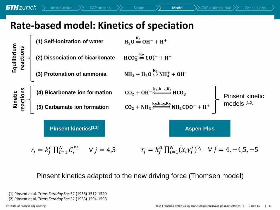
Rate-based model: Kinetics of speciation
(1) Self-ionization of water
(2) Dissociation of bicarbonate
(3) Protonation of ammonia
(4) Bicarbonate ion formation
𝐇𝟐𝐎𝐊𝟏 𝐎𝐇− + 𝐇+
𝐇𝐂𝐎𝟑−𝐊𝟐 𝐂𝐎𝟑
𝟐− + 𝐇+
𝐍𝐇𝟑 + 𝐇𝟐𝐎𝐊𝟑 𝐍𝐇𝟒
+ + 𝐎𝐇−
𝐂𝐎𝟐 +𝐎𝐇−𝐤𝟒,𝐤−𝟒,𝐊𝟒
𝐇𝐂𝐎𝟑−
(5) Carbamate ion formation
Equ
ilib
riu
m
reac
tio
ns
Kin
eti
c re
acti
on
s
𝐂𝐎𝟐 + 𝐍𝐇𝟑𝐤𝟓,𝐤−𝟓,𝐊𝟓
𝐍𝐇𝟐𝐂𝐎𝐎− + 𝐇+
Scope Introduction CAP process Model CAP optimization Conclusions
Pinsent kinetic
models [1,2]
𝑟𝑗 = 𝑘𝑗𝑐 𝐶𝑖
𝜈𝑖𝑁𝑖=1 ∀ 𝑗 = 4,5 𝑟𝑗 = 𝑘𝑗
𝑎 (𝑥𝑖𝛾𝑖∗)𝜈𝑖𝑁
𝑖=1 ∀ 𝑗 = 4, −4,5, −5
Pinsent kinetics[1,2] Aspen Plus
José-Francisco Pérez-Calvo, [email protected]
[1] Pinsent et al. Trans Faraday Soc 52 (1956) 1512-1520 [2] Pinsent et al. Trans Faraday Soc 52 (1956) 1594-1598
Pinsent kinetics adapted to the new driving force (Thomsen model)

| | Institute of Process Engineering 9-Dec-16 José-Francisco Pérez-Calvo, [email protected] 12
Rate-based model validation with CSIRO tests[1]
[1] Yu et al. Chem Eng Res Des 89 (2011) 1204-1215 [2] Qi et al. Int J Greenh Gas Con 17 (2013) 450-461
Scope Introduction CAP process Model CAP optimization Conclusions
𝑇𝑙𝑒𝑎𝑛 = 16.4°C
𝑇𝑙𝑒𝑎𝑛 = 23.9°C
𝑇𝑙𝑒𝑎𝑛 = 27.0°C
Experiment
Model (Liquid)
Model (Vapor)
𝑇𝑐𝑜𝑜𝑙𝑒𝑟 = 15.3°C 𝑇𝑐𝑜𝑜𝑙𝑒𝑟 = 23.1°C
𝑇𝑐𝑜𝑜𝑙𝑒𝑟 = 26.7°C
𝑇𝐹𝐺 = 16.6°C 𝑇𝐹𝐺 = 21.8°C 𝑇𝐹𝐺 = 28.0°C
From literature[2]: Rate-based model with Chen thermodynamic model
This study:
Rate-based model with Thomsen thermodynamic model and adapted kinetic parameters

| | Institute of Process Engineering 9-Dec-16 José-Francisco Pérez-Calvo, [email protected] 13
From rate-based to equilibrium-based simulations Murphree
efficiencies
0.15
0.03
0.23
0.10
NH
3 u
pta
ke
C
O2 u
pta
ke
Scope Introduction CAP process Model CAP optimization Conclusions
Ab
so
rbe
r h
eig
ht
[-]
Temperature [°C]
𝒚𝑪𝑶𝟐 [mole frac]
Rate-based model
Equilibrium model with
new Murphree efficiencies
𝒚𝐂𝐎𝟐𝐅𝐆 = 𝟎. 𝟏𝟖 𝒚𝐂𝐎𝟐
𝐅𝐆 = 𝟎. 𝟐𝟐
Temperature [°C]
𝒚𝑪𝑶𝟐 [mole frac]

| | Institute of Process Engineering 9-Dec-16 José-Francisco Pérez-Calvo, [email protected] 14
Heuristic optimization algorithm
Phase diagram–guided
definition of feasible range
of operating conditons
1
1
CO2 capture > 85 %
CO2 purity > 99 %mole
NH3 slip < 200 ppm
No solid formation
Specifications and
constraints
Scope Introduction CAP process Model CAP optimization Conclusions

| | Institute of Process Engineering 9-Dec-16 José-Francisco Pérez-Calvo, [email protected] 15
Heuristic optimization algorithm
Phase diagram–guided
definition of feasible range
of operating conditons
1
Automated sensitivity
analysis
CO2 absorber
~104 simulations
2
Automated sensitivity
analysis
CO2 capture section
~104 simulations
3
Rigorous optimization
FG-WW section
~103 simulations
4
Objective function
computation
~103 simulations
5
CO2 capture > 85 %
CO2 purity > 99 %mole
NH3 slip < 200 ppm
No solid formation
Specifications and
constraints
3
4
2
Scope Introduction CAP process Model CAP optimization Conclusions

| | Institute of Process Engineering 9-Dec-16 José-Francisco Pérez-Calvo, [email protected] 16
Objective function
Total Specific Exergy Needs 𝑤 =𝑊𝑟𝑒𝑏𝑜𝑖𝑙𝑒𝑟𝑠 +𝑊𝑐ℎ𝑖𝑙𝑙𝑖𝑛𝑔 +𝑊𝑎𝑢𝑥𝑖𝑙𝑖𝑎𝑟𝑖𝑒𝑠
𝑚𝐶𝑂2𝑎𝑏𝑠
MJ
kg CO2 captured
Scope Introduction CAP process Model CAP optimization Conclusions

| | Institute of Process Engineering 9-Dec-16 José-Francisco Pérez-Calvo, [email protected] 17
Heuristic optimization results
𝑤𝑐ℎ𝑖𝑙𝑙𝑖𝑛𝑔
[M
Je
l/kg
CO
2]
𝑤𝑟𝑒𝑏𝑜𝑖𝑙𝑒𝑟𝑠 [MJ/kgCO2]
min 𝑤
𝑤 [M
J/k
gC
O2]
Total Specific Exergy Needs 𝑤 =𝑊𝑟𝑒𝑏𝑜𝑖𝑙𝑒𝑟𝑠 +𝑊𝑐ℎ𝑖𝑙𝑙𝑖𝑛𝑔 +𝑊𝑎𝑢𝑥𝑖𝑙𝑖𝑎𝑟𝑖𝑒𝑠
𝑚𝐶𝑂2𝑎𝑏𝑠
MJ
kg CO2 captured
0.30
0.35
0.25
0.20
0.15
0.10
0.05
0.00
0.75 0.80 0.85 0.90 0.95 1.00 1.05 1.10
0.9
1.0
1.1
1.2
1.3
Scope Introduction CAP process Model CAP optimization Conclusions
𝒚𝐂𝐎𝟐𝐅𝐆 = 𝟎.𝟏𝟖

| | Institute of Process Engineering 9-Dec-16 José-Francisco Pérez-Calvo, [email protected] 18
CO2 absorber profiles for optimum operating conditions
Scope Introduction CAP process Model CAP optimization Conclusions
Cement Plant
Power Plant
22%
18%
14% vol. CO2
Higher L/G
Higher NH3 content
Lower CO2 loading
Combination
Adaptation of
operating conditions
Higher L/G
Lower NH3 content
Constant CO2 loading
Combination

| | Institute of Process Engineering
0.728 0.757 0.753
0.056 0.036 0.029
0.094 0.056 0.034
0.047 0.044
0.041
0
2
4
6
8
10
0.0
0.2
0.4
0.6
0.8
1.0
14% vol. CO2 18% vol. CO2 22% vol. CO2
9-Dec-16 José-Francisco Pérez-Calvo, [email protected] 19
Comparison of results
14% vol. CO2
Scope Introduction CAP process Model CAP optimization Conclusions
18% vol. CO2 22% vol. CO2
To
tal
Sp
ecif
ic E
xerg
y N
eed
s [
MJ/k
gC
O2]
L/G
[kg/k
g]
Cement Plant Power Plant
Chilling Auxiliaries
Reboiler FG-WW
Reboiler CO2 capt
Higher CO2 concentration in the flue gas leads to: Lower exergy needs Increase in the L/G in the CO2 absorber

| | Institute of Process Engineering 9-Dec-16 José-Francisco Pérez-Calvo, [email protected] 20
Conclusions
The Chilled Ammonia Process can be applied for CO2 capture to cement plants
A rate-based model using Thomsen thermodynamic model has been validated with pilot plant tests from the literature
The heuristic optimization approach has led to the optimum set of operating conditions of the process, based on:
Assessment of the energy requirements
Equilibrium model
Thomsen thermodynamic model
Ad-hoc Murphree efficiencies for cement plant flue gas compositions
Scope Introduction CAP process Model CAP optimization Conclusions

| | Institute of Process Engineering 9-Dec-16 José-Francisco Pérez-Calvo, [email protected] 21
Acknowledgements
This project has received funding from the European Union's Horizon 2020 research and innovation programme under grant agreement no 641185
This work was supported by the Swiss State Secretariat for Education, Research and Innovation (SERI) under contract number 15.0160
José-Francisco Pérez-Calvo, Daniel Sutter, Matteo Gazzani, Marco Mazzotti Institute of Process Engineering, ETH Zurich
GHGT-13, November 14-18, 2016
Application of a chilled-ammonia based process for CO2 capture to cement plants