Embed Size (px)
Citation preview
Application Notes
Print Environments
Print Environments

Print Environments i
The ErgoSoft RIP is available in different editions. Therefore the description of available features in this document does not necessarily reflect the license details of your edition of the ErgoSoft RIP. For information on the features included in your edition of the ErgoSoft RIPs refer to the ErgoSoft homepage or contact your dealer.
Rev. 1.1
ErgoSoft AG Moosgrabenstr. 13 CH-8595 Altnau, Switzerland © 2010 ErgoSoft AG, All rights reserved. The information contained in this manual is based on information available at the time of publication and is sub-ject to change without notice. Accuracy and completeness are not warranted or guaranteed. No part of this manual may be reproduced or transmitted in any form or by any means, including electronic me-dium or machine-readable form, without the expressed written permission of ErgoSoft AG. Brand or product names are trademarks of their respective holders.
Print Environments ii
Contents
Introduction ................................................................................................................................................................. 1 Basic Functions ........................................................................................................................................................... 1
Inserting Print Environments ........................................................................................................................... 2 Deleting Print Environments ............................................................................................................................ 3 Managing Print Environments ........................................................................................................................ 3
Configuring Print Environments ........................................................................................................................... 4 Tab “Quality” .......................................................................................................................................................... 4 Dithering Methods .............................................................................................................................................. 6
Basics .................................................................................................................................................................. 6 Smooth Diffusion / Stochastic3e ............................................................................................................. 6 Screen Printing Raster .................................................................................................................................. 8
Tab “Printer and Port” ........................................................................................................................................ 9 Tab “Printing Ink Assignment” ..................................................................................................................... 10 Tab “Ink Control” ............................................................................................................................................... 12 Tab “Media Size” ............................................................................................................................................... 13 Tab “Ink Cost” ..................................................................................................................................................... 14 Tab “Device Options” ...................................................................................................................................... 14 Tab “General” ..................................................................................................................................................... 15 Tab “Extras” ......................................................................................................................................................... 16
Print Environments 1
1
Introduction
The print environment is the cornerstone of the ErgoSoft RIPs. It allows you to define all the necessary information and settings to print on a particular printer/media/ink combination. It contains the printer driver, the dithering method, the linearization of the printer, the output profile, the total ink limit, the port used, and other device settings. In order to get the best printing result, we strongly recommend creating separate print environments for each prin-ter/media/ink combination. For the printout, the print environment is simply selected from the list. Thus, for a certain media, the same configuration may be used without having to se-lect the data every time. All data are selected automatically when the appropriate print envi-ronment has been selected.
The Print Environment Manager is started by clicking this icon in the Print Envi-ronment toolbar or by selecting menu Tools > Print Environments.
Basic Functions
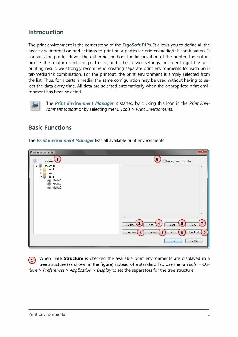
The Print Environment Manager lists all available print environments:
When Tree Structure is checked the available print environments are displayed in a tree structure (as shown in the figure) instead of a standard list. Use menu Tools > Op-
tions > Preferences > Application > Display to set the separators for the tree structure.
1
4
6
7 3 1
5 8 2
9
Print Environments 2
2
3
4
Inserting Print Environments
Download: The ErgoSoft RIPs offer a number of predefined print environments avail-able on the web. When the connection to the Print Environment Server is established,
you may select the print environments that fit best to your current combination of printer, ink, and media. The print environments can be imported directly after the download and/or saved somewhere in your local or network environment for later import on the same or another system. If the imported print environment already exists, overwriting must be con-firmed. Please note that the computer must have internet access in order to download print envi-ronments.
Import: Print environments that are saved on any data media available from the cur-rent computer system (such as network drive, CD, DVD, etc.) may be imported into the
ErgoSoft RIPs. Just navigate to the source folder and select the print environments to be imported. If the imported print environment already exists, overwriting must be confirmed.
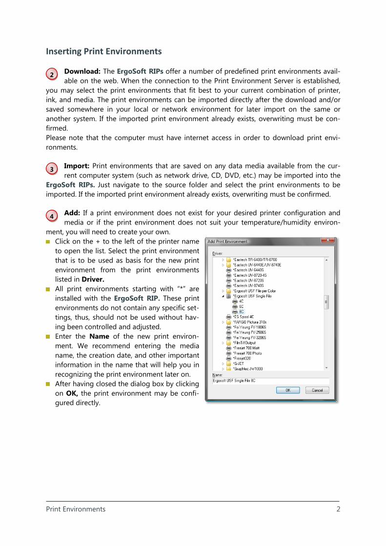
Add: If a print environment does not exist for your desired printer configuration and media or if the print environment does not suit your temperature/humidity environ-
ment, you will need to create your own. Click on the + to the left of the printer name
to open the list. Select the print environment that is to be used as basis for the new print environment from the print environments listed in Driver.
All print environments starting with “*” are installed with the ErgoSoft RIP. These print environments do not contain any specific set-tings, thus, should not be used without hav-ing been controlled and adjusted.
Enter the Name of the new print environ-ment. We recommend entering the media name, the creation date, and other important information in the name that will help you in recognizing the print environment later on.
After having closed the dialog box by clicking on OK, the print environment may be confi-gured directly.
Print Environments 3
5
7
8
9
6
Deleting Print Environments
Remove: When you do not need the print environment any longer, you may remove it from the print environment list as well as from your hard disk.
Managing Print Environments
Rename: The name of the selected print environment can be modified when needed.
Copy: Copying an existing print environment may be useful when you just need to make some changes to the current settings for testing purposes or others. This function
can also be used to add a new print environment that is based on the settings of a current one.
Export: Print environments can be exported in order to save them on any location on your system e.g. for transferring them to another system. Select the location of the ex-
ported print environment in another dialog box; the name of the print environment in the list of print environments will be the name of the exported print environment file. When more than one print environments are selected (not available in the Tree Structure), a print envi-ronment package is exported.
Manage write protection: To secure a print environment from being modified acci-dentally, it can set to be ‘write protected’ (read only). Please note that this function only
works on the selected print environment when the box is checked while closing the Print Environment Manager with OK.
Print Environments 4
1
1
2
3
Configuring Print Environments
Settings: The settings of a print environment can be accessed from the Print Environment Manager or by clicking this icon in the Print Environment toolbar.
The print environment has a minimum of 5 tabs for standard settings: General, Quality, Printer and Port, Extras, and Media Size. When the printer allows changing the default slot settings for the ink cartridges another tab Printing Ink Assignment is available. Additional tabs Ink Control, Ink Cost, and Device Options are available for most printers. Please note that the availability of configuration options highly depends on the selected basic printer driver. The global option Archive print environment before changing allows automatically creat-ing a backup copy of the original print environment in the standard archive folder.
Tab “Quality”
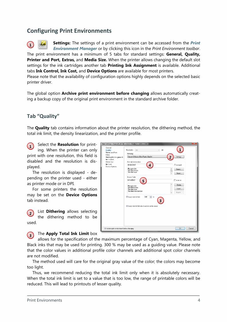
The Quality tab contains information about the printer resolution, the dithering method, the total ink limit, the density linearization, and the printer profile.
Select the Resolution for print-ing. When the printer can only
print with one resolution, this field is disabled and the resolution is dis-played.
The resolution is displayed - de-pending on the printer used - either as printer mode or in DPI.
For some printers the resolution may be set on the Device Options tab instead.
List Dithering allows selecting the dithering method to be
used.
The Apply Total Ink Limit box allows for the specification of the maximum percentage of Cyan, Magenta, Yellow, and
Black inks that may be used for printing. 300 % may be used as a guiding value. Please note that the color values in additional profile color channels and additional spot color channels are not modified.
The method used will care for the original gray value of the color; the colors may become too light.
Thus, we recommend reducing the total ink limit only when it is absolutely necessary. When the total ink limit is set to a value that is too low, the range of printable colors will be reduced. This will lead to printouts of lesser quality.
1
2
3
4
5
Print Environments 5
4
5
Check Apply Ink Limit on top of Printer Profile to limit the amount of ink for Cyan, Ma-genta, Yellow, and Black always to the specified ink limit – even if the printer profile has a higher ink limit. Please note that this may result in color changes – especially when the prin-ter profile has 5 or more color channels (e.g. CMYKOG) because the values in the additional color channels are not modified by the ink limit.
Dialog part Density Linearization allows a pre-defined density linearization to be loaded.
By default, the density linearization is part of the print environment file (embedded). When checking external, an external density linearization file can be selected for the print environ-ment. Click on the arrow next to the name of the current density linearization file to get a list of the available density linearization files from which one may be selected. A short descrip-tion of the selected density linearization file is displayed in the box below the name. Uncheck external to embed the external density linearization file into the print environment. Please note that the print environment with the external density linearization must be saved (closed and re-opened) before you can embed the density linearization.
Clicking on Delete removes the selected density linearization after confirmation from the print environment or from the hard disk - depending on whether it is an embedded or exter-nal density linearization.
Embedded density linearizations can be exported into external density linearization files by clicking on the Export button.
The creation of a density linearization is described in the density manual.
Dialog part Printer Profile allows a pre-defined printer profile to be loaded. Printer profiles are created using the optional ColorGPS profiler to adjust the output to
the inks and media. Printing takes more time when a printer profile is used. By default, the printer profile is part of the print environment file (embedded). When
checking external an external printer profile can be selected for the print environment. Click on the arrow next to the name of the current printer profile to get a list of the available prin-ter profiles from which one may be selected. A short description of the selected printer pro-file is displayed in the box below the name. Uncheck external to embed the external printer profile into the print environment. Please note that the print environment with the external printer profile must be saved (closed and re-opened) before you can embed the printer pro-file.
Clicking on Delete removes the selected printer profile after confirmation from the print environment or from the hard disk - depending on whether it is an embedded or external printer profile.
Embedded printer profiles can be exported into external printer profiles by clicking on the Export button.
Clicking on Import allows copying printer profiles to the folder in which the ErgoSoft RIP expects them to be copied. ErgoSoft AG does not guarantee that profiles that are not created with help of the optional ColorGPS profiler can be used by the ErgoSoft RIP.
Print Environments 6
When not having selected a printer profile and printing RGB images (always with input profile) or Lab images or CMYK images with input profile, the ErgoSoft RIP will use a default separation. The default separation causes the gray value component of a color to be printed with black and CMY. In most cases this will improve the print quality.
The creation of a printer profiles with the optional ColorGPS profiler is described in the ColorGPS manual.
Dithering Methods
Basics
There are two groups of raster types: irregular rasters and regular rasters. Regular rasters: Screen Printing Applications. It can look like pictures in newspapers.
Screen printing Applications can be customized and is used for screen printing. Irregular or random like rasters: Smooth Diffusion and Stochastic3e which both can be
customized. Both Smooth Diffusion and Stochastic3e can handle more than 4 dilutions of one ink (e.g.
6 or 7 black tones). When changing the dithering method (raster) or the settings for a raster, creating a new
density linearization is recommended.
Smooth Diffusion / Stochastic3e
Smooth Diffusion is based on a Floyd Steinberg error diffusion with special care for more than one light ink per color combined with variable dots. The features are:
Reduction of vermicular artifacts in very light halftones Reduction of noise and structural artifacts in the transition from light ink to full tone ink Supporting combinations of light inks and dot sizes with more than 4 components (e.g.
variable dot with light cyan and very light cyan) Possibility to limit the use of small and medium dot sizes to get good rasters, especially on
“difficult” printers such as Roland Possibility to optimize the raster result for printers with artifacts in the printout in order to
reduce printing artifacts such as horizontal lines (banding) as well as vertical striation (caused by crimped media or transportation rolls)
Stochastic3e is a frequency modulated raster. The detail sharpness is less than the one at Smooth Diffusion. However, the program consumes less calculation time than Smooth Diffu-sion.
Print Environments 7
1
2
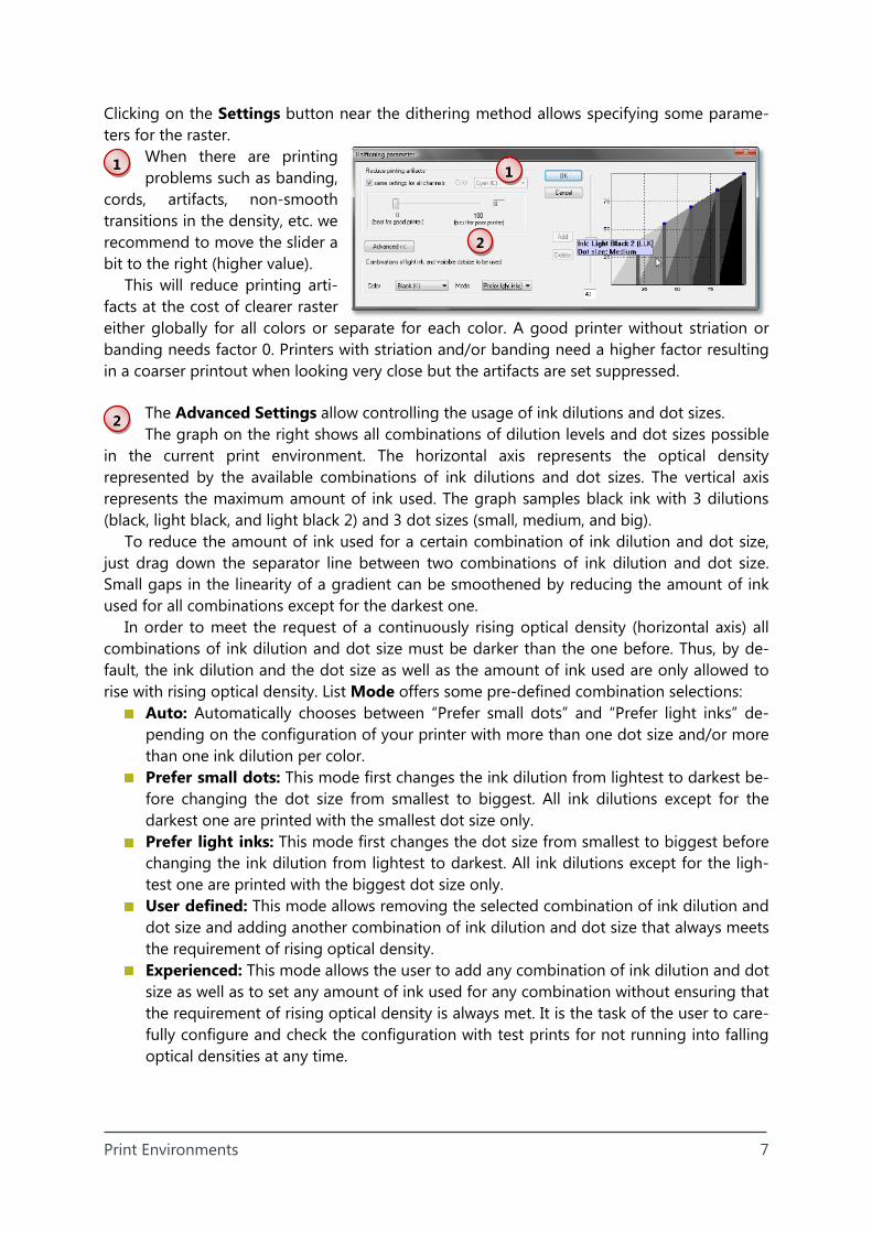
Clicking on the Settings button near the dithering method allows specifying some parame-ters for the raster.
When there are printing problems such as banding,
cords, artifacts, non-smooth transitions in the density, etc. we recommend to move the slider a bit to the right (higher value).
This will reduce printing arti-facts at the cost of clearer raster either globally for all colors or separate for each color. A good printer without striation or banding needs factor 0. Printers with striation and/or banding need a higher factor resulting in a coarser printout when looking very close but the artifacts are set suppressed.
The Advanced Settings allow controlling the usage of ink dilutions and dot sizes. The graph on the right shows all combinations of dilution levels and dot sizes possible
in the current print environment. The horizontal axis represents the optical density represented by the available combinations of ink dilutions and dot sizes. The vertical axis represents the maximum amount of ink used. The graph samples black ink with 3 dilutions (black, light black, and light black 2) and 3 dot sizes (small, medium, and big).
To reduce the amount of ink used for a certain combination of ink dilution and dot size, just drag down the separator line between two combinations of ink dilution and dot size. Small gaps in the linearity of a gradient can be smoothened by reducing the amount of ink used for all combinations except for the darkest one.
In order to meet the request of a continuously rising optical density (horizontal axis) all combinations of ink dilution and dot size must be darker than the one before. Thus, by de-fault, the ink dilution and the dot size as well as the amount of ink used are only allowed to rise with rising optical density. List Mode offers some pre-defined combination selections:
Auto: Automatically chooses between “Prefer small dots” and “Prefer light inks” de-pending on the configuration of your printer with more than one dot size and/or more than one ink dilution per color.
Prefer small dots: This mode first changes the ink dilution from lightest to darkest be-fore changing the dot size from smallest to biggest. All ink dilutions except for the darkest one are printed with the smallest dot size only.
Prefer light inks: This mode first changes the dot size from smallest to biggest before changing the ink dilution from lightest to darkest. All ink dilutions except for the ligh-test one are printed with the biggest dot size only.
User defined: This mode allows removing the selected combination of ink dilution and dot size and adding another combination of ink dilution and dot size that always meets the requirement of rising optical density.
Experienced: This mode allows the user to add any combination of ink dilution and dot size as well as to set any amount of ink used for any combination without ensuring that the requirement of rising optical density is always met. It is the task of the user to care-fully configure and check the configuration with test prints for not running into falling optical densities at any time.
1
2
Print Environments 8
1
2
3
Screen Printing Raster
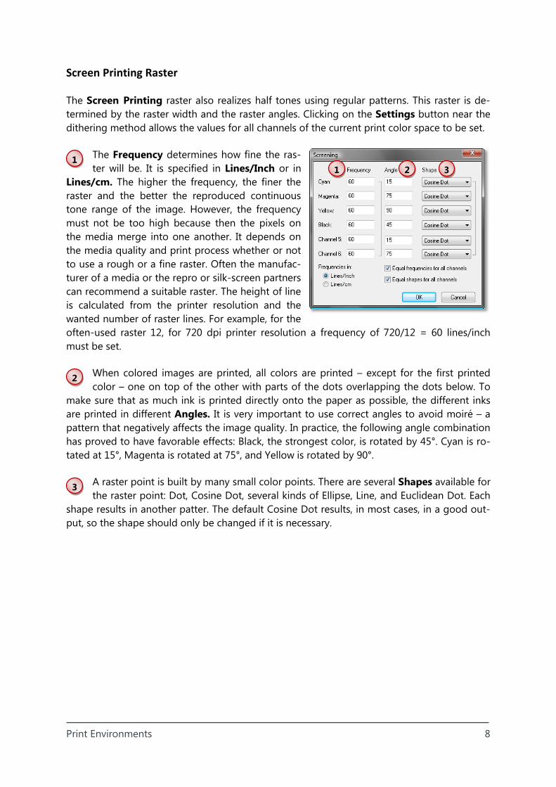
The Screen Printing raster also realizes half tones using regular patterns. This raster is de-termined by the raster width and the raster angles. Clicking on the Settings button near the dithering method allows the values for all channels of the current print color space to be set.
The Frequency determines how fine the ras-ter will be. It is specified in Lines/Inch or in
Lines/cm. The higher the frequency, the finer the raster and the better the reproduced continuous tone range of the image. However, the frequency must not be too high because then the pixels on the media merge into one another. It depends on the media quality and print process whether or not to use a rough or a fine raster. Often the manufac-turer of a media or the repro or silk-screen partners can recommend a suitable raster. The height of line is calculated from the printer resolution and the wanted number of raster lines. For example, for the often-used raster 12, for 720 dpi printer resolution a frequency of 720/12 = 60 lines/inch must be set.
When colored images are printed, all colors are printed – except for the first printed color – one on top of the other with parts of the dots overlapping the dots below. To
make sure that as much ink is printed directly onto the paper as possible, the different inks are printed in different Angles. It is very important to use correct angles to avoid moiré – a pattern that negatively affects the image quality. In practice, the following angle combination has proved to have favorable effects: Black, the strongest color, is rotated by 45°. Cyan is ro-tated at 15°, Magenta is rotated at 75°, and Yellow is rotated by 90°.
A raster point is built by many small color points. There are several Shapes available for the raster point: Dot, Cosine Dot, several kinds of Ellipse, Line, and Euclidean Dot. Each
shape results in another patter. The default Cosine Dot results, in most cases, in a good out-put, so the shape should only be changed if it is necessary.
1 3 2
Print Environments 9
1
2
For printers with fast connections such as Mimaki JV5, Canon printers and others as well as all Mimaki printers connected to the firewire port, we strongly recommend using the Print Client instead of printing directly to the port.
3
4
5
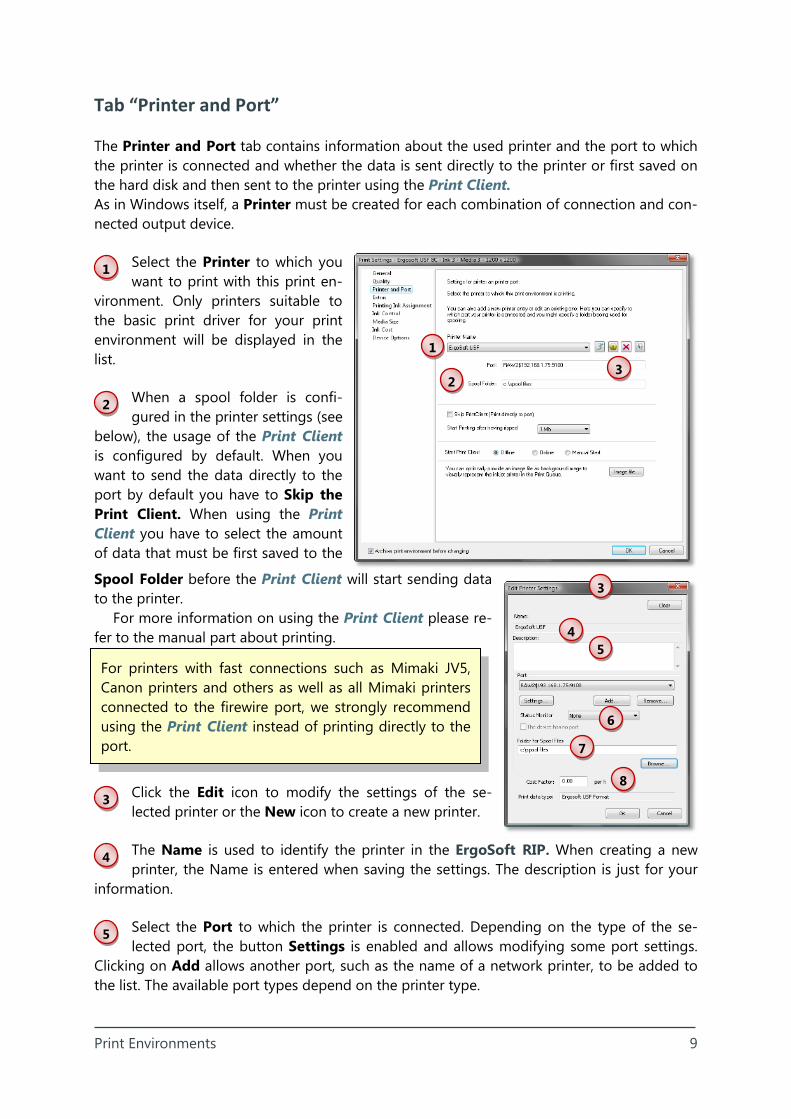
Tab “Printer and Port”
The Printer and Port tab contains information about the used printer and the port to which the printer is connected and whether the data is sent directly to the printer or first saved on the hard disk and then sent to the printer using the Print Client. As in Windows itself, a Printer must be created for each combination of connection and con-nected output device.
Select the Printer to which you want to print with this print en-
vironment. Only printers suitable to the basic print driver for your print environment will be displayed in the list.
When a spool folder is confi-gured in the printer settings (see
below), the usage of the Print Client is configured by default. When you want to send the data directly to the port by default you have to Skip the Print Client. When using the Print Client you have to select the amount of data that must be first saved to the
Spool Folder before the Print Client will start sending data to the printer.
For more information on using the Print Client please re-fer to the manual part about printing.
Click the Edit icon to modify the settings of the se-lected printer or the New icon to create a new printer.
The Name is used to identify the printer in the ErgoSoft RIP. When creating a new printer, the Name is entered when saving the settings. The description is just for your
information.
Select the Port to which the printer is connected. Depending on the type of the se-lected port, the button Settings is enabled and allows modifying some port settings.
Clicking on Add allows another port, such as the name of a network printer, to be added to the list. The available port types depend on the printer type.
1
2 3
3
8
7
6
5 4
Print Environments 10
When adding a TCP/IP port, we strongly recommend using one of the RAW protocol types: RAW for socket version 1.1 and RAW (2) for socket version 2.
6
7
8
1
The other protocol types are designed for tests with small amounts of data only and can cause severe problems when used in the production. Hint: The Port for the RAW protocol types often is 9100.
Select the Status Monitor type that can be displayed in the Print Client. Please note that the status monitor type must match your printer type. The status monitor is not
available for all printer types.
Select a folder in which the ripped data for this printer will be saved when the data is not sent directly to the printer. This is the spool folder in which the Print Client for this
printer will look for data that can be sent to the printer.
Enter the Cost Factor for the ripping time. This value is used to calculate the computer time dependent part of the production costs that are displayed in the information to
the ripped and printed job.
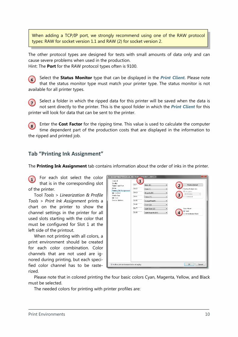
Tab “Printing Ink Assignment”
The Printing Ink Assignment tab contains information about the order of inks in the printer.
For each slot select the color that is in the corresponding slot
of the printer. Tool Tools > Linearization & Profile
Tools > Print Ink Assignment prints a chart on the printer to show the channel settings in the printer for all used slots starting with the color that must be configured for Slot 1 at the left side of the printout.
When not printing with all colors, a print environment should be created for each color combination. Color channels that are not used are ig-nored during printing, but each speci-fied color channel has to be raste-rized.
Please note that in colored printing the four basic colors Cyan, Magenta, Yellow, and Black must be selected.
The needed colors for printing with printer profiles are:
1
3
2
4
Print Environments 11
2
3
4
When the specified color order does not meet the actual color order in the printer, “in-correct” colors will be printed.
CMYK as first four color channels; Orange/Red, Green, Blue/Violet are used as profile channels 5, 6, 7; followed by “Profile channel 8”, “Profile channel 9”, etc. When one or more of the colors “Orange/Red”, “Green”, and “Blue/Violet” are not used they simply can be skipped.
Example: Ink colors are CMYK, bright blue, Azure, Navy Blue, Lavender (4 blue tones)
Since “Blue” can be selected for only one of the four blue tones (e.g. for “bright blue”), the other three blue tones must be labeled “Profile channel 8”, “Profile channel 9”, “Profile chan-nel 10”. This means for the printer profile: CMYK are channels 1 to 4, “Blue” is channel 5, “Profile channel 8” is channel 6, “Profile channel 9” is channel 7, and “Profile channel 10” is channel 8.
Click Restore Default to restore the default printing ink assignment for the current print environment. Please note that this will overwrite your modifications (except set-
tings for spot colors) without warning.
When your printer can be equipped with two or three cartridges with the same ink (e.g. 2x CMYK) you may want to use two or three cartridges of the same ink color simulta-
neously. Check Allow Multiple Inks in order to select the same ink color in several slots. The method As Layers will use all cartridges with the same ink color together to double or
triple the density of the color. When using a variable dot sizes you can specify the dot size for which you want to use the multiple inks. This method has the same effect as printing several ink layers but is much faster.
Selecting Distributed will print with all cartridges of the same color, but with only one at a time. The used cartridges are chosen randomly. This method lets you print longer before you have to refill the ink.
In some versions of the ErgoSoft RIP the As Layers mode is only available in the mo-nochrome color model.
Normally, the used Color Model is “Color”. When the printer is set up for monochrome printing with several dilutions of the black ink you can select the color model “Monoch-
rome Black” in order to use black and light black inks only. For more information on the monochrome color model please refer to the manual part
about monochrome printing.
Print Environments 12
1
2
3
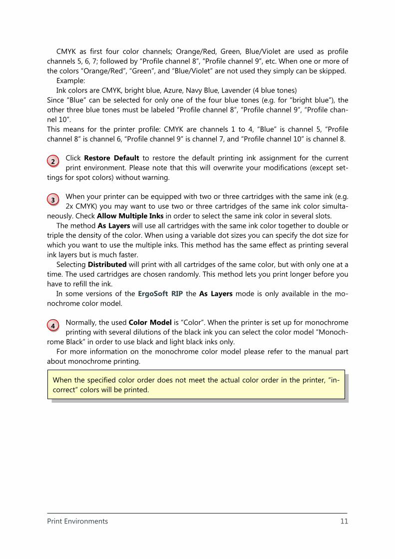
Tab “Ink Control”
The Ink Control tab allows configuring the ink control strips printed automatically with each job.
The Production Strip allows printing small strips along the
left and/or right side of the job in or-der to prevent ink heads from becom-ing dry.
Since the production strip is not meant for being used as visual control whether the heads are printing cor-rectly, all heads can print at the same position. Thus, the available ink slots are divided into the available number of strips (Strip Count) with a configur-able maximum amount of ink used (Coverage).
The Visual Control Strip allows printing strips along the left
and/or right side of the job with all inks visible for visual control of the condition of the print heads and nozzles.
Mode Dot Sizes in Row prints patches for all dot sizes of one ink color side by side re-quiring the strip width for each dot size. The specified number of shades of each ink color is printed one under the other along the job length – one color after the other.
Mode One Column prints patches for all combinations of dot sizes and specified shades of one ink color one under the other along the job length – one color after the other. Thus, the strip always has just one patch in width.
Mode Continuous prints strips for all combinations of dot sizes and specified shades of one ink color side by side requiring the strip width for each combination of dot size and shade – one color after the other along the job width.
The required width at the left and/or right side of the job for the specified strips inform about the reduction of the job width resulting from the current configuration.
3
2
1
Print Environments 13
1
2
3
4
5
6
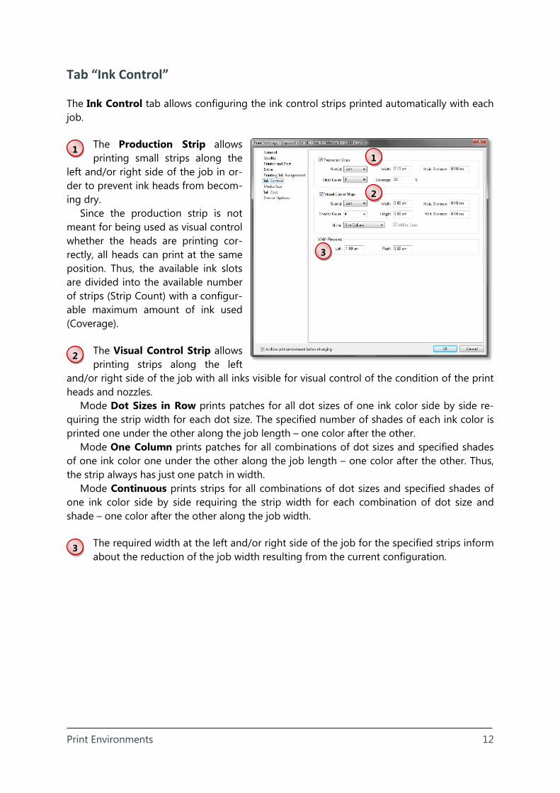
Tab “Media Size”
The Media Size tab allows setting a default media size for all jobs created with this print en-vironment.
Check Use as default for this print environment to specify a
media format and margins that are always used as default when a new job is created for the current print environment.
Please note that this setting will override the settings for the global media size for all jobs created when the current print environment is se-lected.
Select the default Media Size for new jobs. The Width and
Height of the selected format are displayed under the list. The rotated orientation can be selected if it is available for the selected format. When the selected printer allows checking the width of the inserted media you can also get the media size from the printer.
Check currently appropriate to limit the list to those media that fit into the printable area of the current printer. Check roll media only to limit the media size list to roll
formats only.
Specify the Margins on the media that will not be printed. Mark minimum to use the minimum margins provided by the printer. Borderless is only activated when the cur-
rent print driver (print environment) allows to print without margins for the selected media size.
An unlimited number of media size lists can be saved (exported) and later reloaded. The button Import allows re-importing media sizes from the predefined System Files or
another media size list (User Files) into the current list.
Use the tool buttons to modify the media size list. This list is printer-independent which means that it holds all available media sizes independent whether they can be used
with the current printer or not. Pre-defined media sizes installed with the ErgoSoft RIP cannot be modified in the set-
tings. Media size “+Maximum+” cannot be modified at all nor deleted.
6
5
4
3
2
1
Print Environments 14
7
2
1
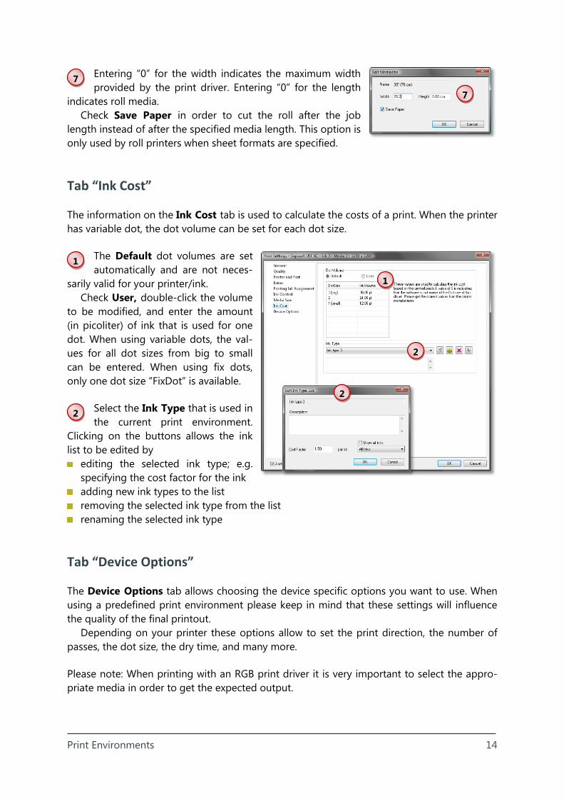
Entering “0” for the width indicates the maximum width provided by the print driver. Entering “0” for the length
indicates roll media. Check Save Paper in order to cut the roll after the job
length instead of after the specified media length. This option is only used by roll printers when sheet formats are specified.
Tab “Ink Cost”
The information on the Ink Cost tab is used to calculate the costs of a print. When the printer has variable dot, the dot volume can be set for each dot size.
The Default dot volumes are set automatically and are not neces-
sarily valid for your printer/ink. Check User, double-click the volume
to be modified, and enter the amount (in picoliter) of ink that is used for one dot. When using variable dots, the val-ues for all dot sizes from big to small can be entered. When using fix dots, only one dot size “FixDot” is available.
Select the Ink Type that is used in the current print environment.
Clicking on the buttons allows the ink list to be edited by
editing the selected ink type; e.g. specifying the cost factor for the ink
adding new ink types to the list removing the selected ink type from the list renaming the selected ink type
Tab “Device Options”
The Device Options tab allows choosing the device specific options you want to use. When using a predefined print environment please keep in mind that these settings will influence the quality of the final printout.
Depending on your printer these options allow to set the print direction, the number of passes, the dot size, the dry time, and many more.
Please note: When printing with an RGB print driver it is very important to select the appro-priate media in order to get the expected output.
7
1
2
2
Print Environments 15
1
2
3
4
5
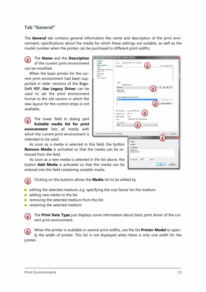
Tab “General”
The General tab contains general information like name and description of the print envi-ronment, specifications about the media for which these settings are suitable, as well as the model number when the printer can be purchased in different print widths.
The Name and the Description of the current print environment
can be modified. When the basic printer for the cur-
rent print environment had been sup-ported in older versions of the Ergo-Soft RIP, Use Legacy Driver can be used to set the print environment format to the old version in which the new layout for the control strips is not available.
The lower field in dialog part Suitable media list for print
environment lists all media with which the current print environment is intended to be used.
As soon as a media is selected in this field, the button Remove Media is activated so that the media can be re-moved from the field.
As soon as a new media is selected in the list above, the button Add Media is activated so that this media can be entered into the field containing suitable media.
Clicking on the buttons allows the Media list to be edited by
editing the selected medium; e.g. specifying the cost factor for the medium adding new media to the list removing the selected medium from the list renaming the selected medium
The Print Data Type just displays some information about basic print driver of the cur-rent print environment.
When the printer is available in several print widths, use the list Printer Model to speci-fy the width of printer. This list is not displayed when there is only one width for the
printer.
5
4
3
3
2
1
Print Environments 16
1
2
3
4
5
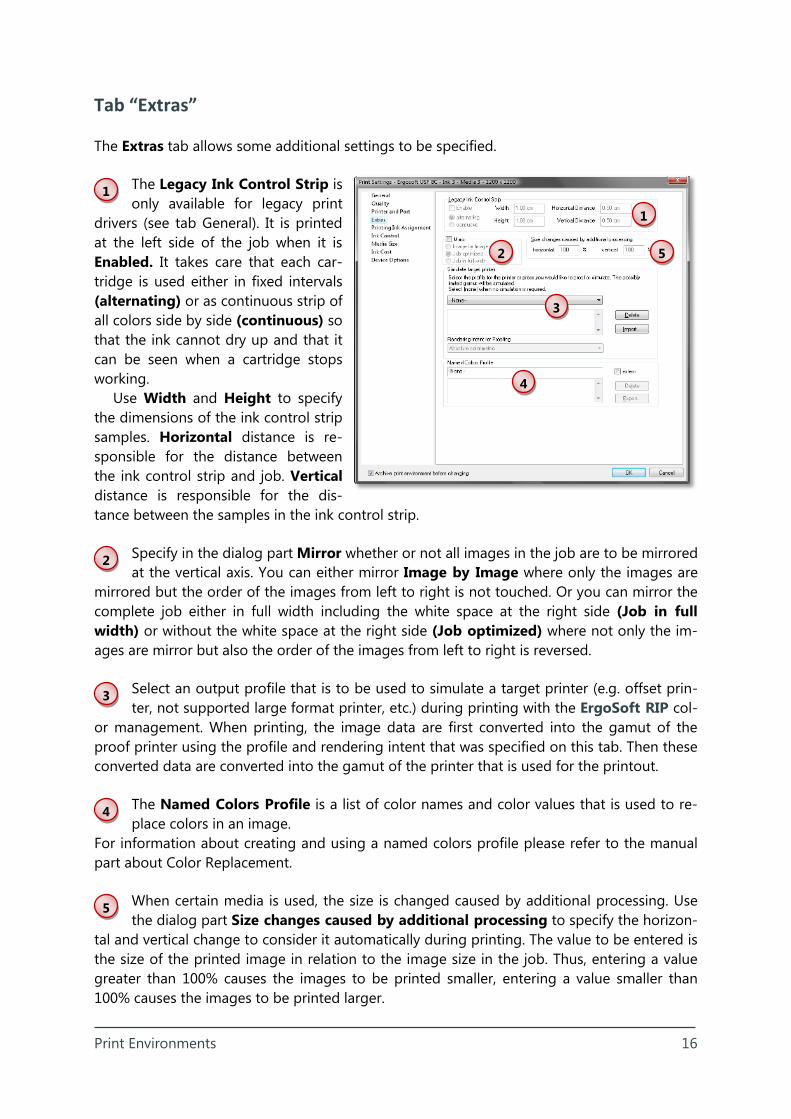
Tab “Extras”
The Extras tab allows some additional settings to be specified.
The Legacy Ink Control Strip is only available for legacy print
drivers (see tab General). It is printed at the left side of the job when it is Enabled. It takes care that each car-tridge is used either in fixed intervals (alternating) or as continuous strip of all colors side by side (continuous) so that the ink cannot dry up and that it can be seen when a cartridge stops working.
Use Width and Height to specify the dimensions of the ink control strip samples. Horizontal distance is re-sponsible for the distance between the ink control strip and job. Vertical distance is responsible for the dis-tance between the samples in the ink control strip.
Specify in the dialog part Mirror whether or not all images in the job are to be mirrored at the vertical axis. You can either mirror Image by Image where only the images are
mirrored but the order of the images from left to right is not touched. Or you can mirror the complete job either in full width including the white space at the right side (Job in full width) or without the white space at the right side (Job optimized) where not only the im-ages are mirror but also the order of the images from left to right is reversed.
Select an output profile that is to be used to simulate a target printer (e.g. offset prin-ter, not supported large format printer, etc.) during printing with the ErgoSoft RIP col-
or management. When printing, the image data are first converted into the gamut of the proof printer using the profile and rendering intent that was specified on this tab. Then these converted data are converted into the gamut of the printer that is used for the printout.
The Named Colors Profile is a list of color names and color values that is used to re-place colors in an image.
For information about creating and using a named colors profile please refer to the manual part about Color Replacement.
When certain media is used, the size is changed caused by additional processing. Use the dialog part Size changes caused by additional processing to specify the horizon-
tal and vertical change to consider it automatically during printing. The value to be entered is the size of the printed image in relation to the image size in the job. Thus, entering a value greater than 100% causes the images to be printed smaller, entering a value smaller than 100% causes the images to be printed larger.
1
2
3
4
5

Print Environments 17