Embed Size (px)
Citation preview
STB; Reviewed:
SPOC 11/10/2012
Solution & Interoperability Test Lab Application Notes
©2012 Avaya Inc. All Rights Reserved.
1 of 95
L31K75SM61SBC60
Avaya Solution & Interoperability Test Lab
Application Notes for Configuring Level 3 SIP Trunking
with the Avaya Communication Server 1000 Release 7.5,
Avaya Aura® Session Manager Release 6.1 and Avaya
Aura® Session Border Controller Release 6.0.2 - Issue 1.0
Abstract
These Application Notes describe the steps to configure Session Initiation Protocol (SIP)
Trunking between Level 3 SIP Trunking service and an Avaya SIP-enabled enterprise
solution. The Avaya solution consists of Avaya Aura® Session Border Controller 6.2, Avaya
Aura® Session Manager 6.1, Avaya Communication Server 1000 7.5 and various Avaya
endpoints. During the interoperability testing, Avaya Communication Server 1000 was able to
interoperate with Level 3 via SIP trunk. This test was performed to verify SIP trunk features
including basic call, call forward (all calls, busy, no answer), call transfer (blind and consult),
conference and voice mail. The calls are placed in both directions with various set types.
This documented solution does not extend to configurations without Avaya Aura® Session
Border Controller or Avaya Aura® Session Manager.
Information in these Application Notes has been obtained through DevConnect compliance
testing and additional technical discussions. Testing was conducted via the DevConnect
Program at the Avaya Solution and Interoperability Test Lab.
STB; Reviewed:
SPOC 11/10/2012
Solution & Interoperability Test Lab Application Notes
©2012 Avaya Inc. All Rights Reserved.
2 of 95
L31K75SM61SBC60
Table of Contents
1. Introduction ............................................................................................................................. 4 2. General Test Approach and Test Results ................................................................................ 5
2.1. Interoperability Compliance Testing ................................................................................ 5 2.2. Test Results ...................................................................................................................... 5
2.2.1. Blind Transfer ........................................................................................................... 6
2.2.2. History-Info and Diversion Headers ......................................................................... 6 2.2.3. SIP Header Optimization .......................................................................................... 6 2.2.4. G.711 Fax .................................................................................................................. 6 2.2.5. Emergency 911/E911 Services Limitations and Restrictions ................................... 6 2.2.6. Toll Free .................................................................................................................... 7
2.3. Support ............................................................................................................................. 7 3. Reference Configuration ......................................................................................................... 8
4. Equipment and Software Validated ...................................................................................... 10 5. Avaya Communication Server 1000 Configuration ............................................................. 13
5.1. Login to CS1000E System ............................................................................................. 13 5.1.1. Login Unified Communications Management and Element Manager ................... 13
5.1.2. Login to Call Server Command Line Interface (CLI) ............................................ 14 5.2. Administer a Node IP Telephony ................................................................................... 15
5.2.1. Obtain Node IP address .......................................................................................... 15
5.2.2. Administer TPS ....................................................................................................... 16 5.2.3. Administer Quality of Service (QoS) ..................................................................... 17
5.2.4. Synchronize the New Configuration ....................................................................... 18 5.3. Administer Voice Codec ................................................................................................ 18
5.3.1. Enable Voice Codec, Node IP Telephony. ............................................................. 18 5.3.2. Enable Voice Codec on Media Gateways. .............................................................. 20
5.4. Administer Zones and Bandwidth .................................................................................. 23
5.4.1. Create a zone for IP phones (zone 10) .................................................................... 23 5.4.2. Create a zone for virtual SIP trunk (zone 255) ....................................................... 25
5.5. Administer SIP Trunk Gateway ..................................................................................... 26
5.5.1. Integrated Services Digital Network (ISDN) .......................................................... 26 5.5.2. Administer SIP Trunk Gateway to Session Manager ............................................. 28
5.5.3. Administer Virtual D-Channel ................................................................................ 30 5.5.4. Administer Virtual Super-Loop .............................................................................. 34 5.5.5. Enable Music for Customer Data Block ................................................................. 35
5.5.6. Administer Virtual SIP Routes ............................................................................... 35
5.5.7. Administer Virtual Trunks ...................................................................................... 39
5.5.8. Administer Calling Line Identification Entries....................................................... 43 5.5.9. Enable External Trunk to Trunk Transferring ........................................................ 44
5.6. Administer Dialing Plans ............................................................................................... 45 5.6.1. Define ESN Access Codes and Parameters (ESN) ................................................. 45 5.6.2. Associate NPA and SPN call to ESN Access Code 1 ............................................. 46
5.6.3. Digit Manipulation Block (DMI) ............................................................................ 47 5.6.4. Route List Block (RLB) (RLB 100) ....................................................................... 48
STB; Reviewed:
SPOC 11/10/2012
Solution & Interoperability Test Lab Application Notes
©2012 Avaya Inc. All Rights Reserved.
3 of 95
L31K75SM61SBC60
5.6.5. Inbound Call Digit Translation ............................................................................... 49
5.6.6. Outbound Call - Special Number Configuration. ................................................... 51 5.6.7. Outbound Call - Numbering Plan Area (NPA) ....................................................... 52
5.7. Administer Phone ........................................................................................................... 53
5.7.1. Phone creation ......................................................................................................... 53 5.7.2. Enable Privacy for Phone ........................................................................................ 55 5.7.3. Enable Call Forward for Phone............................................................................... 57 5.7.4. Enable Call Waiting for Phone ............................................................................... 59
6. Administer Avaya Aura® Session Manager......................................................................... 60
6.1. Create a SIP domain name ............................................................................................. 60 6.2. Create a Location ........................................................................................................... 62 6.3. Create SIP Entity for Session Manager .......................................................................... 63 6.4. Create SIP Entity for CS1000E SIP Gateway ................................................................ 65
6.5. Create SIP Entity for Avaya Aura® Packet SBC .......................................................... 66 6.6. Create Routing Policy for inbound call .......................................................................... 67
6.7. Create Routing Policy for outbound call ........................................................................ 69 6.8. Create Dial Pattern for inbound call ............................................................................... 69
6.9. Create Dial Pattern for outbound call ............................................................................. 71 6.10. Add Adaptation Module ............................................................................................. 75
7. Configure Avaya Aura® Session Border Controller ............................................................ 79
7.1. Post Installation Configuration....................................................................................... 79 7.2. Options Frequency ......................................................................................................... 79
7.3. Blocked Headers ............................................................................................................ 80 7.4. Allow Header Modification ........................................................................................... 82 7.5. Third Party Call Control ................................................................................................. 86
7.6. Save the Configuration ................................................................................................... 87
8. Verification Steps ................................................................................................................. 88 8.1. General ........................................................................................................................... 88 8.2. Verify Call Establishment on CS1000E Call Server ...................................................... 88
8.3. Protocol Traces ............................................................................................................... 89 9. Conclusion ............................................................................................................................ 93
10. Additional References ........................................................................................................... 94
STB; Reviewed:
SPOC 11/10/2012
Solution & Interoperability Test Lab Application Notes
©2012 Avaya Inc. All Rights Reserved.
4 of 95
L31K75SM61SBC60
1. Introduction This document provides a typical network configuration deployment of the Avaya
Communication Server 1000E (hereafter referred to as CS1000E) and the Level 3 SIP Trunking
(hereafter referred to as Level 3). During the interoperability testing, all SIP trunk applicable
feature test cases were executed to ensure the interoperability between the Level 3 system and
the Avaya CS1000E 7.5, Avaya Aura® Session Manager Release 6.1 and Avaya Aura® Session
Border Controller Release 6.2 system.
STB; Reviewed:
SPOC 11/10/2012
Solution & Interoperability Test Lab Application Notes
©2012 Avaya Inc. All Rights Reserved.
5 of 95
L31K75SM61SBC60
2. General Test Approach and Test Results The CS1000E system release 7.5 was connected to an Avaya Aura® Session Border Controller
(hearafter referred to as the Avaya Aura® SBCvia the Avaya Aura® Session Manager (hereafter
referred to as Session Manager).Then the Avaya Aura® SBC was connected to the Level 3
system via SIP trunk. Various call types were made from the CS1000E to Level 3 and vice versa
to ensure the interoperability between the systems.
Level 3 is a member of the Avaya DevConnect Service Provider program. DevConnect
Compliance Testing is conducted jointly by Avaya and DevConnect members. The jointly-
defined test plan focuses on exercising APIs and/or standards-based interfaces pertinent to the
interoperability of the tested products and their functionalities. DevConnect Compliance Testing
is not intended to substitute full product performance or feature testing performed by
DevConnect members, nor is it to be construed as an endorsement by Avaya of the suitability or
completeness of a DevConnect member’s solution.
2.1. Interoperability Compliance Testing The focus of this testing is to verify that CS1000E release 7.5 can interoperate with the Level 3.
The following interoperability areas were covered.
General call processing between CS1000E and Level 3 systems including:
- Codec (G.711 u-law and G.729/ ptime 20ms/ VAD disabled).
- Hold/Retrieve on both ends.
- Music On Hold.
- CLID displays.
- Ring-back tone.
- Speech paths.
- Dialing plan support.
- Advanced features (Call on Mute, Call Park, and Call Waiting).
- Abandoned Call.
Call redirection verification: all supported methods (blind transfer, consultative
transfer, call forward, and conference) including CLID. Call redirection was
performed from both ends.
RFC2833/DTMF on both directions.
SIP Transport UDP with Digest Authentication.
SIP Digest Authentication.
Thru dialing via PBX Call Pilot.
Voice Mail Server CallPilot (hosted on CS1000E).
Fax Transmission: the fax call was transmitted from both ends with codec T.38.
Early Media Transmission.
2.2. Test Results The general test approach was to configure a simulated enterprise site using the CS1000E,
Session Manager and the Avaya Aura® SBC to connect to the Level 3 SIP Trunking service.
STB; Reviewed:
SPOC 11/10/2012
Solution & Interoperability Test Lab Application Notes
©2012 Avaya Inc. All Rights Reserved.
6 of 95
L31K75SM61SBC60
This configuration, shown in Figure 3.1, was used to exercise the features and functionality
listed in Section 2.1.
Interoperability testing of Level 3 SIP Trunking service with the Avaya SIP-enabled enterprise
solution was completed with successful results with the exception of the observations/limitations
described in this section.
2.2.1. Blind Transfer
In the default configuration, the CS1000E will not allow a blind transfer to be executed if the SIP
trunk service, in this case Level 3, does not support the SIP UPDATE method. With the
installation of plug-in 501 on the CS1000E, the blind transfer will be allowed and the call will be
completed. The limitation of this plugin is that no ringback is provided to the originator of the
call for the duration that the destination set is ringing. In addition to plug-in 501, it is required
that VTRK SU version “cs1000-vtrk-7.50.17.16-15.i386.000.ntl”, as detailed in Section 4, or
higher be used on all SSG signaling servers to ensure proper operation of the blind transfer
feature.
Example scenario:
Assume a call is active between a CS1000E telephone user and a PSTN user “A”. To allow the
CS1000E user to transfer the call using the Level 3 SIP Trunk service to another PSTN user B
before user B has answered the call, CS1000E plug-in 501 must be enabled as shown in Section
4. While plug-in 501 will allow the CS1000E user to complete the transfer operation, user A will
not hear ring back tone while user B is ringing in this case. PSTN users A and B will have two-
way talk path once user B answers.
2.2.2. History-Info and Diversion Headers
The Level 3 service does not support SIP History-Info headers. The Level 3 service requires that
SIP Diversion Header be sent for certain redirected calls (e.g. Call Forward). Session Manager is
used to convert the History Info header into the Diversion Header by the use of the adaptation
“DiversionTypeAdapter” for these types of calls. For all other calls, the Avaya Aura® SBC will
strip off History-Info headers.
2.2.3. SIP Header Optimization
SIP header rules were implemented on the Avaya Aura® SBC to streamline the SIP header and
remove any unnecessary parts. The following headers were removed: X_nt_e_164_clid,
Alert_Info, P-Location, P-Site, Alert-Info, History-Info, x-nt-corr-id and P-Asserted-Identity.
Also the multipart MIME SDP, which included the x-nt-mcdn-frag-hex, x-nt-epid-frag and x-nt-
inforeq/8000, was stripped out. These particular headers and MIME have no real use in the
service provider network and their presence may add unnecessary confusion.
2.2.4. G.711 Fax
G.711 fax is not supported in the reference configuration. T.38 faxing is supported, as is Group 3
and Super Group 3 fax. Fax speeds to 14400 bps are supported in the configuration tested.
2.2.5. Emergency 911/E911 Services Limitations and Restrictions
STB; Reviewed:
SPOC 11/10/2012
Solution & Interoperability Test Lab Application Notes
©2012 Avaya Inc. All Rights Reserved.
7 of 95
L31K75SM61SBC60
911/E911 test calls were not made during the testing of this solution. Although Level 3 provides
911/E911 calling capabilities, Level 3 does not warrant or represent that the equipment and
software reviewed in this customer configuration guide will properly operate to complete
911/E911 calls; therefore, it is the customer’s responsibility to ensure proper operation with the
equipment/software vendor.
2.2.6. Toll Free
Inbound toll free calls were not tested as part of this solution.
2.3. Support
For technical support on Level 3 system, please contact Level 3 technical support at:
Toll Free: 1-877-4LEVEL3 (1-877-453-8353)
http://www.level-3.voip.com/en/contact-us/
Avaya customers may obtain documentation and support for Avaya products by visiting
http://support.avaya.com. Selecting the Support Contact Options link followed by Maintenance
Support provides the worldwide support directory for Avaya Global Services. Specific numbers
are provided for both customers and partners based on the specific type of support or
consultation services needed. Some services may require specific Avaya service support
agreements. Alternatively, in the United States, (866) GO-AVAYA (866-462-8292) provides
access to overall sales and service support menus.
STB; Reviewed:
SPOC 11/10/2012
Solution & Interoperability Test Lab Application Notes
©2012 Avaya Inc. All Rights Reserved.
8 of 95
L31K75SM61SBC60
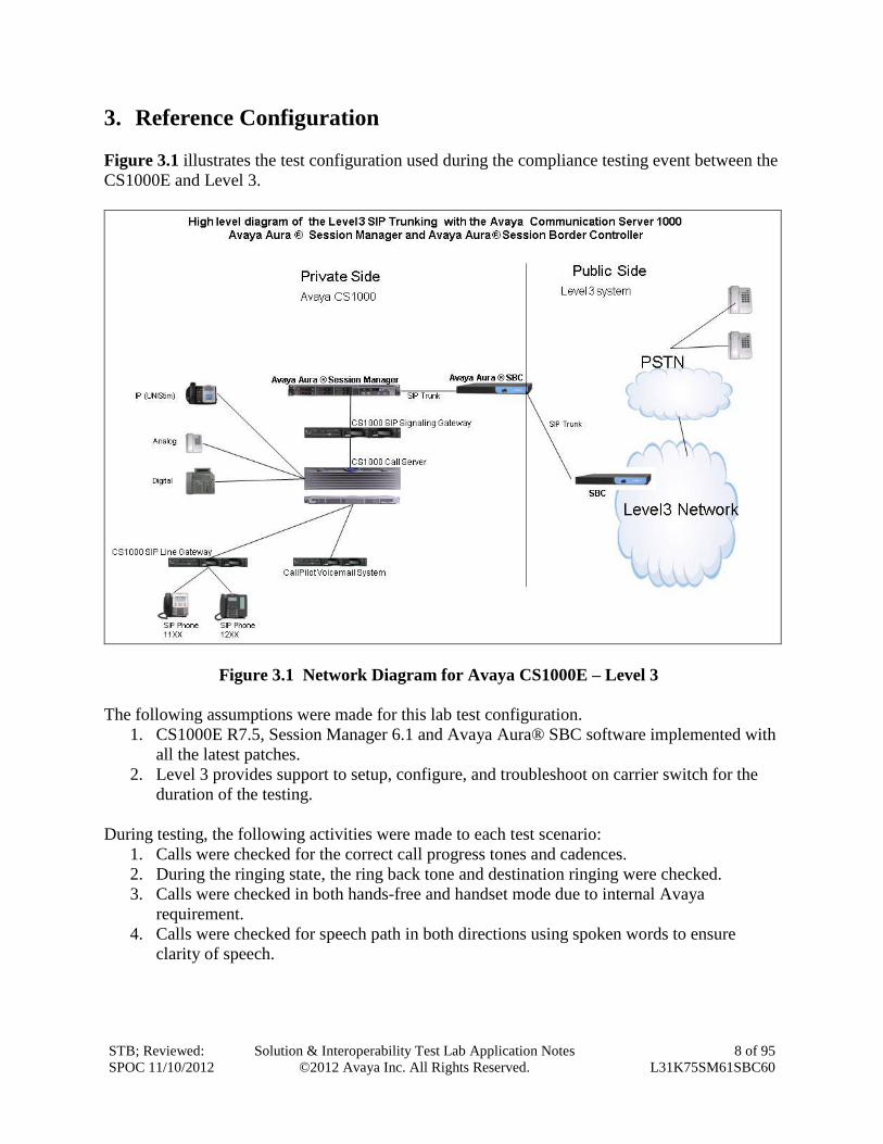
3. Reference Configuration
Figure 3.1 illustrates the test configuration used during the compliance testing event between the
CS1000E and Level 3.
Figure 3.1 Network Diagram for Avaya CS1000E – Level 3
The following assumptions were made for this lab test configuration.
1. CS1000E R7.5, Session Manager 6.1 and Avaya Aura® SBC software implemented with
all the latest patches.
2. Level 3 provides support to setup, configure, and troubleshoot on carrier switch for the
duration of the testing.
During testing, the following activities were made to each test scenario:
1. Calls were checked for the correct call progress tones and cadences.
2. During the ringing state, the ring back tone and destination ringing were checked.
3. Calls were checked in both hands-free and handset mode due to internal Avaya
requirement.
4. Calls were checked for speech path in both directions using spoken words to ensure
clarity of speech.
STB; Reviewed:
SPOC 11/10/2012
Solution & Interoperability Test Lab Application Notes
©2012 Avaya Inc. All Rights Reserved.
9 of 95
L31K75SM61SBC60
5. The display(s) of the sets/clients involved were checked for consistent and expected
CLID, name and redirection information both prior to answer and after call
establishment.
6. The speech path and messaging system were observed for timely and quality End to End
tone audio path generation and application responses.
7. The call server maintenance terminal window was used for the monitoring of BUG(s),
ERR and AUD messages.
8. Speech path and display checked before and after calls were put on/off hold from each
end.
9. Applicable files were screened on an hourly basis during the testing for messages that
may indicate technical issues. This refers to Avaya PBX files.
10. Calls were checked to ensure that all resources such as Virtual trunks, TDM trunks, Sets
and VGWs are released when a call scenario ends.
The Fully Qualified Domain Names and IP addressing specified in these Application Notes
apply only to the reference configuration shown in Figure 3.1. Avaya uses a combination of
FQDNs and IP addresses, the Level 3 network is IP address based.
For confidentiality purposes, the IP addresses in these Application notes have been modified to
show 111.x.x.x for Avaya internal addresses, 222.x.x.x for Avaya external address and 333.x.x.x
for Level 3 external address. Level 3 customers will use their own FQDNs and IP addresses as
required
STB; Reviewed:
SPOC 11/10/2012
Solution & Interoperability Test Lab Application Notes
©2012 Avaya Inc. All Rights Reserved.
10 of 95
L31K75SM61SBC60
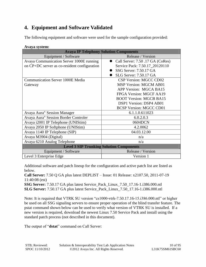
4. Equipment and Software Validated
The following equipment and software were used for the sample configuration provided:
Avaya system:
Avaya IP Telephony Solution Components
Equipment / Software Release / Version
Avaya Communication Server 1000E running
on CP+DC server as co-resident configuration
Call Server: 7.50 .17 GA (CoRes)
Service Pack: 7.50.17_20120110
SSG Server: 7.50.17 GA
SLG Server: 7.50.17 GA
Communication Server 1000E Media
Gateway
CSP Version: MGCC CD02
MSP Version: MGCM AB01
APP Version: MGCA BA15
FPGA Version: MGCF AA19
BOOT Version: MGCB BA15
DSP1 Version: DSP4 AB01
BCSP Version: MGCC CD01
Avaya Aura® Session Manager 6.1.1.0.611023
Avaya Aura® Session Border Controler 6.0.2.0.3
Avaya i2001 IP Telephone (UNIStim) 0604DCN
Avaya 2050 IP Softphone (UNIStim) 4.2.0062
Avaya 1140 IP Telephone (SIP) 04.03.12.00
Avaya M3904 (Digital) n/a
Avaya 6210 Analog Telephone n/a
Level 3 SIP Trunking Solution Components
Equipment / Software Release / Version
Level 3 Enterprise Edge Version 1
Additional software and patch lineup for the configuration and active patch list are listed as
below.
Call Server: 7.50 Q GA plus latest DEPLIST – Issue: 01 Release: x2107.50, 2011-07-19
11:40:08 (est)
SSG Server: 7.50.17 GA plus latest Service_Pack_Linux_7.50_17.16-1.i386.000.ntl
SLG Server: 7.50.17 GA plus latest Service_Pack_Linux_7.50_17.16-1.i386.000.ntl
Note: It is required that VTRK SU version “cs1000-vtrk-7.50.17.16-15.i386.000.ntl” or higher
be used on all SSG signaling servers to ensure proper operation of the blind transfer feature. The
pstat command shown below can be used to verify what version of VTRK SU is installed. If a
new version is required, download the newest Linux 7.50 Service Pack and install using the
standard patch process (not described in this document).
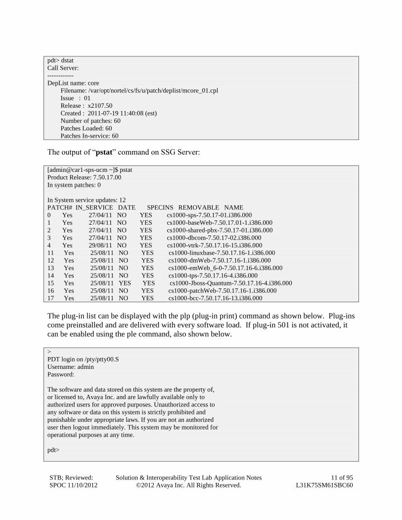
The output of “dstat” command on Call Server:
STB; Reviewed:
SPOC 11/10/2012
Solution & Interoperability Test Lab Application Notes
©2012 Avaya Inc. All Rights Reserved.
11 of 95
L31K75SM61SBC60
pdt> dstat
Call Server:
------------
DepList name: core
Filename: /var/opt/nortel/cs/fs/u/patch/deplist/mcore_01.cpl
Issue : 01
Release : x2107.50
Created : 2011-07-19 11:40:08 (est)
Number of patches: 60
Patches Loaded: 60
Patches In-service: 60
The output of “pstat” command on SSG Server:
[admin@car1-sps-ucm ~]$ pstat
Product Release: 7.50.17.00
In system patches: 0
In System service updates: 12
PATCH# IN_SERVICE DATE SPECINS REMOVABLE NAME
0 Yes 27/04/11 NO YES cs1000-sps-7.50.17-01.i386.000
1 Yes 27/04/11 NO YES cs1000-baseWeb-7.50.17.01-1.i386.000
2 Yes 27/04/11 NO YES cs1000-shared-pbx-7.50.17-01.i386.000
3 Yes 27/04/11 NO YES cs1000-dbcom-7.50.17-02.i386.000
4 Yes 29/08/11 NO YES cs1000-vtrk-7.50.17.16-15.i386.000
11 Yes 25/08/11 NO YES cs1000-linuxbase-7.50.17.16-1.i386.000
12 Yes 25/08/11 NO YES cs1000-dmWeb-7.50.17.16-1.i386.000
13 Yes 25/08/11 NO YES cs1000-emWeb_6-0-7.50.17.16-6.i386.000
14 Yes 25/08/11 NO YES cs1000-tps-7.50.17.16-4.i386.000
15 Yes 25/08/11 YES YES cs1000-Jboss-Quantum-7.50.17.16-4.i386.000
16 Yes 25/08/11 NO YES cs1000-patchWeb-7.50.17.16-1.i386.000
17 Yes 25/08/11 NO YES cs1000-bcc-7.50.17.16-13.i386.000
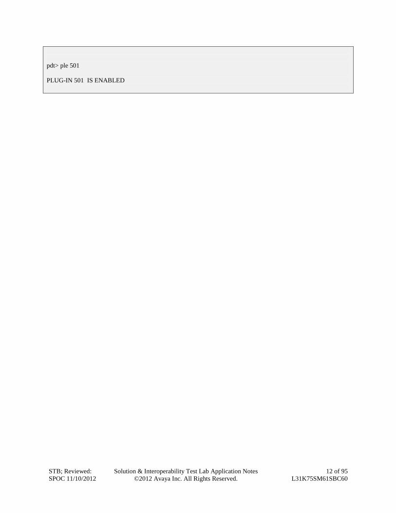
The plug-in list can be displayed with the plp (plug-in print) command as shown below. Plug-ins
come preinstalled and are delivered with every software load. If plug-in 501 is not activated, it
can be enabled using the ple command, also shown below.
>
PDT login on /pty/ptty00.S
Username: admin
Password:
The software and data stored on this system are the property of,
or licensed to, Avaya Inc. and are lawfully available only to
authorized users for approved purposes. Unauthorized access to
any software or data on this system is strictly prohibited and
punishable under appropriate laws. If you are not an authorized
user then logout immediately. This system may be monitored for
operational purposes at any time.
pdt>
STB; Reviewed:
SPOC 11/10/2012
Solution & Interoperability Test Lab Application Notes
©2012 Avaya Inc. All Rights Reserved.
12 of 95
L31K75SM61SBC60
pdt> ple 501
PLUG-IN 501 IS ENABLED
STB; Reviewed:
SPOC 11/10/2012
Solution & Interoperability Test Lab Application Notes
©2012 Avaya Inc. All Rights Reserved.
13 of 95
L31K75SM61SBC60
5. Avaya Communication Server 1000 Configuration These Application Notes assume that the basic configuration has already been administered. For
further information on Avaya Communications Server 1000, please consult references in
Additional References.
The below procedures describe the configuration details of CS1000E with a SIP trunk to the
Level 3 system.
5.1. Login to CS1000E System
5.1.1. Login Unified Communications Management and Element Manager
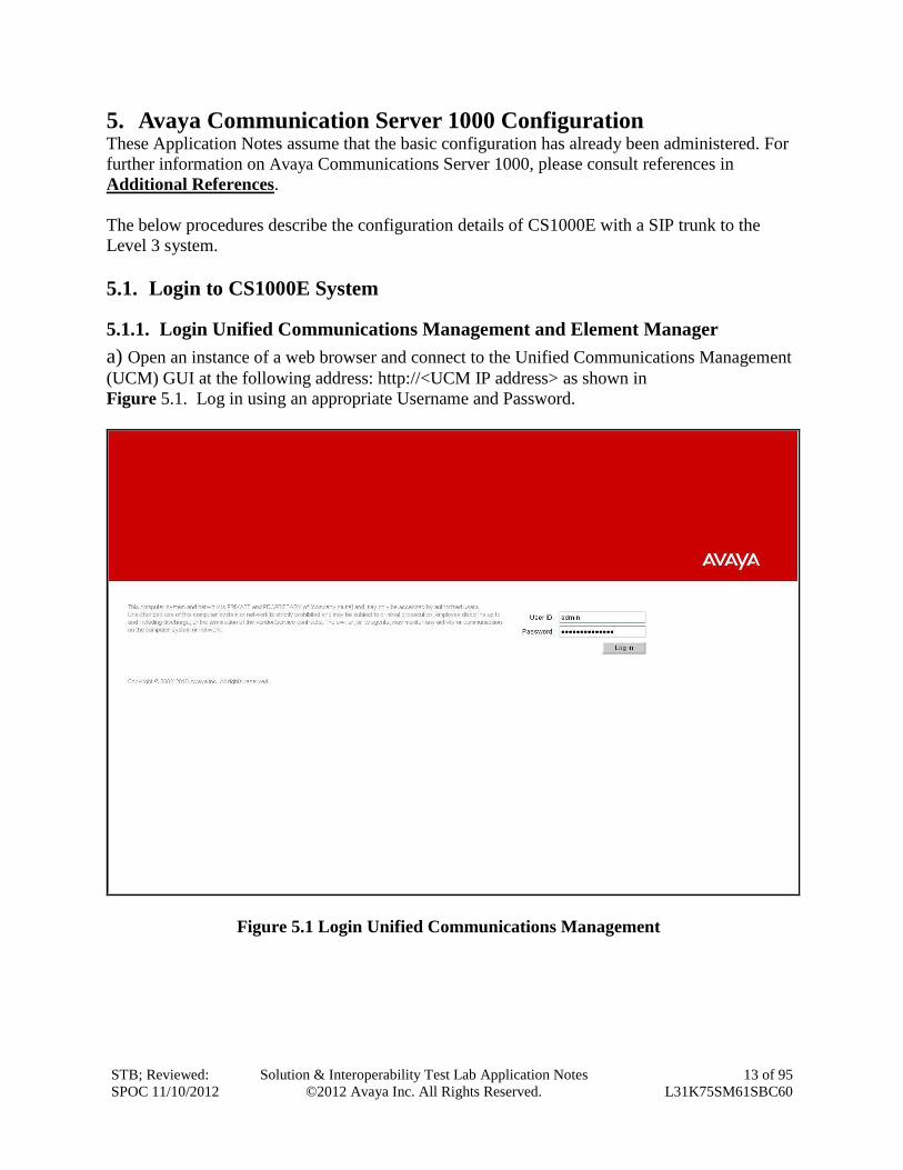
a) Open an instance of a web browser and connect to the Unified Communications Management
(UCM) GUI at the following address: http://<UCM IP address> as shown in
Figure 5.1. Log in using an appropriate Username and Password.
Figure 5.1 Login Unified Communications Management
STB; Reviewed:
SPOC 11/10/2012
Solution & Interoperability Test Lab Application Notes
©2012 Avaya Inc. All Rights Reserved.
14 of 95
L31K75SM61SBC60
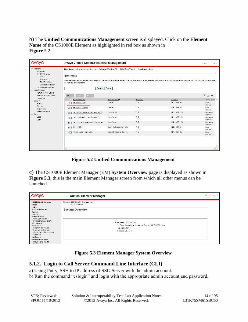
b) The Unified Communications Management screen is displayed. Click on the Element
Name of the CS1000E Element as highlighted in red box as shown in
Figure 5.2.
Figure 5.2 Unified Communications Management
c) The CS1000E Element Manager (EM) System Overview page is displayed as shown in
Figure 5.3, this is the main Element Manager screen from which all other menus can be
launched.
Figure 5.3 Element Manager System Overview
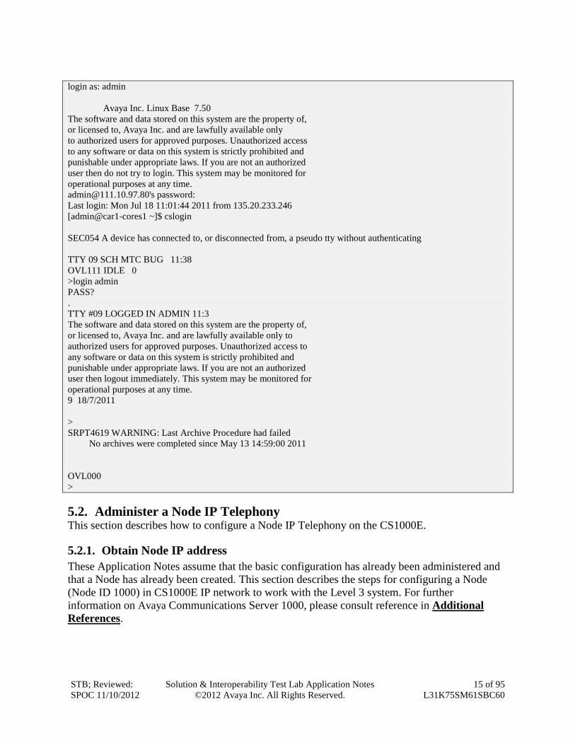
5.1.2. Login to Call Server Command Line Interface (CLI)
a) Using Putty, SSH to IP address of SSG Server with the admin account.
b) Run the command “cslogin” and login with the appropriate admin account and password.
STB; Reviewed:
SPOC 11/10/2012
Solution & Interoperability Test Lab Application Notes
©2012 Avaya Inc. All Rights Reserved.
15 of 95
L31K75SM61SBC60
login as: admin
Avaya Inc. Linux Base 7.50
The software and data stored on this system are the property of,
or licensed to, Avaya Inc. and are lawfully available only
to authorized users for approved purposes. Unauthorized access
to any software or data on this system is strictly prohibited and
punishable under appropriate laws. If you are not an authorized
user then do not try to login. This system may be monitored for
operational purposes at any time.
[email protected]'s password:
Last login: Mon Jul 18 11:01:44 2011 from 135.20.233.246
[admin@car1-cores1 ~]$ cslogin
SEC054 A device has connected to, or disconnected from, a pseudo tty without authenticating
TTY 09 SCH MTC BUG 11:38
OVL111 IDLE 0
>login admin
PASS?
.
TTY #09 LOGGED IN ADMIN 11:3
The software and data stored on this system are the property of,
or licensed to, Avaya Inc. and are lawfully available only to
authorized users for approved purposes. Unauthorized access to
any software or data on this system is strictly prohibited and
punishable under appropriate laws. If you are not an authorized
user then logout immediately. This system may be monitored for
operational purposes at any time.
9 18/7/2011
>
SRPT4619 WARNING: Last Archive Procedure had failed
No archives were completed since May 13 14:59:00 2011
OVL000
>
5.2. Administer a Node IP Telephony This section describes how to configure a Node IP Telephony on the CS1000E.
5.2.1. Obtain Node IP address
These Application Notes assume that the basic configuration has already been administered and
that a Node has already been created. This section describes the steps for configuring a Node
(Node ID 1000) in CS1000E IP network to work with the Level 3 system. For further
information on Avaya Communications Server 1000, please consult reference in Additional
References.
STB; Reviewed:
SPOC 11/10/2012
Solution & Interoperability Test Lab Application Notes
©2012 Avaya Inc. All Rights Reserved.
16 of 95
L31K75SM61SBC60
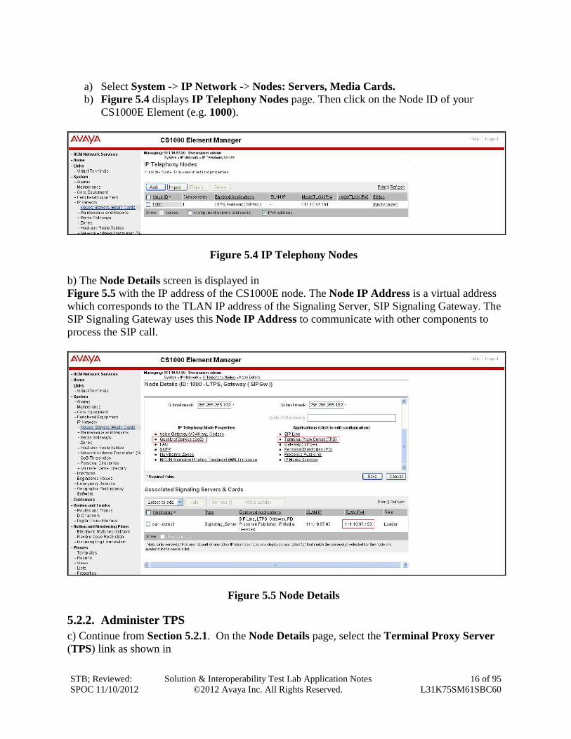
a) Select System -> IP Network -> Nodes: Servers, Media Cards.
b) Figure 5.4 displays IP Telephony Nodes page. Then click on the Node ID of your
CS1000E Element (e.g. 1000).
Figure 5.4 IP Telephony Nodes
b) The Node Details screen is displayed in
Figure 5.5 with the IP address of the CS1000E node. The Node IP Address is a virtual address
which corresponds to the TLAN IP address of the Signaling Server, SIP Signaling Gateway. The
SIP Signaling Gateway uses this Node IP Address to communicate with other components to
process the SIP call.
Figure 5.5 Node Details
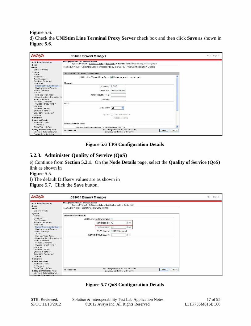
5.2.2. Administer TPS
c) Continue from Section 5.2.1. On the Node Details page, select the Terminal Proxy Server
(TPS) link as shown in
STB; Reviewed:
SPOC 11/10/2012
Solution & Interoperability Test Lab Application Notes
©2012 Avaya Inc. All Rights Reserved.
17 of 95
L31K75SM61SBC60
Figure 5.6.
d) Check the UNIStim Line Terminal Proxy Server check box and then click Save as shown in
Figure 5.6.
Figure 5.6 TPS Configuration Details
5.2.3. Administer Quality of Service (QoS)
e) Continue from Section 5.2.1. On the Node Details page, select the Quality of Service (QoS)
link as shown in
Figure 5.5.
f) The default Diffserv values are as shown in
Figure 5.7. Click the Save button.
Figure 5.7 QoS Configuration Details
STB; Reviewed:
SPOC 11/10/2012
Solution & Interoperability Test Lab Application Notes
©2012 Avaya Inc. All Rights Reserved.
18 of 95
L31K75SM61SBC60
5.2.4. Synchronize the New Configuration
g) Continue from Section 5.2.3, return to the Node Details page in
Figure 5.5 and click on the Save button.
h) The Node Saved screen is displayed. Click on the Transfer Now (not shown).
i) The Synchronize Configuration Files screen is displayed. Check the Signaling Server check
box and click on the Start Sync (not shown).
j) When the synchronization completes, check the Signaling Server check box and click on the
Restart Applications (not shown).
5.3. Administer Voice Codec
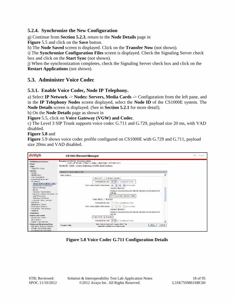
5.3.1. Enable Voice Codec, Node IP Telephony.
a) Select IP Network -> Nodes: Servers, Media Cards -> Configuration from the left pane, and
in the IP Telephony Nodes screen displayed, select the Node ID of the CS1000E system. The
Node Details screen is displayed. (See in Section 5.2.1 for more detail).
b) On the Node Details page as shown in
Figure 5.5, click on Voice Gateway (VGW) and Codec.
c) The Level 3 SIP Trunk supports voice codec G.711 and G.729, payload size 20 ms, with VAD
disabled.
Figure 5.8 and
Figure 5.9 shows voice codec profile configured on CS1000E with G.729 and G.711, payload
size 20ms and VAD disabled.
Figure 5.8 Voice Codec G.711 Configuration Details
STB; Reviewed:
SPOC 11/10/2012
Solution & Interoperability Test Lab Application Notes
©2012 Avaya Inc. All Rights Reserved.
19 of 95
L31K75SM61SBC60
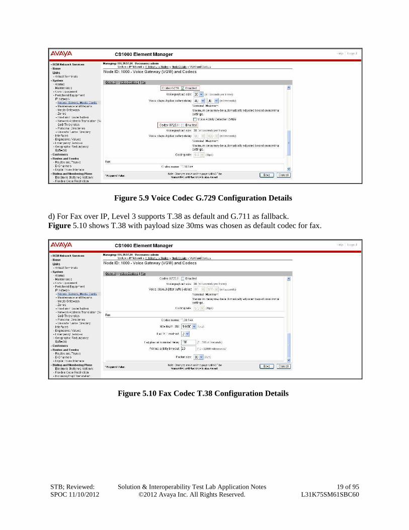
Figure 5.9 Voice Codec G.729 Configuration Details
d) For Fax over IP, Level 3 supports T.38 as default and G.711 as fallback.
Figure 5.10 shows T.38 with payload size 30ms was chosen as default codec for fax.
Figure 5.10 Fax Codec T.38 Configuration Details
STB; Reviewed:
SPOC 11/10/2012
Solution & Interoperability Test Lab Application Notes
©2012 Avaya Inc. All Rights Reserved.
20 of 95
L31K75SM61SBC60
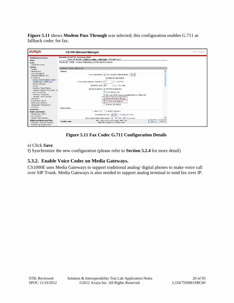
Figure 5.11 shows Modem Pass Through was selected; this configuration enables G.711 as
fallback codec for fax.
Figure 5.11 Fax Codec G.711 Configuration Details
e) Click Save.
f) Synchronize the new configuration (please refer to Section 5.2.4 for more detail)
5.3.2. Enable Voice Codec on Media Gateways.
CS1000E uses Media Gateways to support traditional analog/ digital phones to make voice call
over SIP Trunk. Media Gateways is also needed to support analog terminal to send fax over IP.
STB; Reviewed:
SPOC 11/10/2012
Solution & Interoperability Test Lab Application Notes
©2012 Avaya Inc. All Rights Reserved.
21 of 95
L31K75SM61SBC60
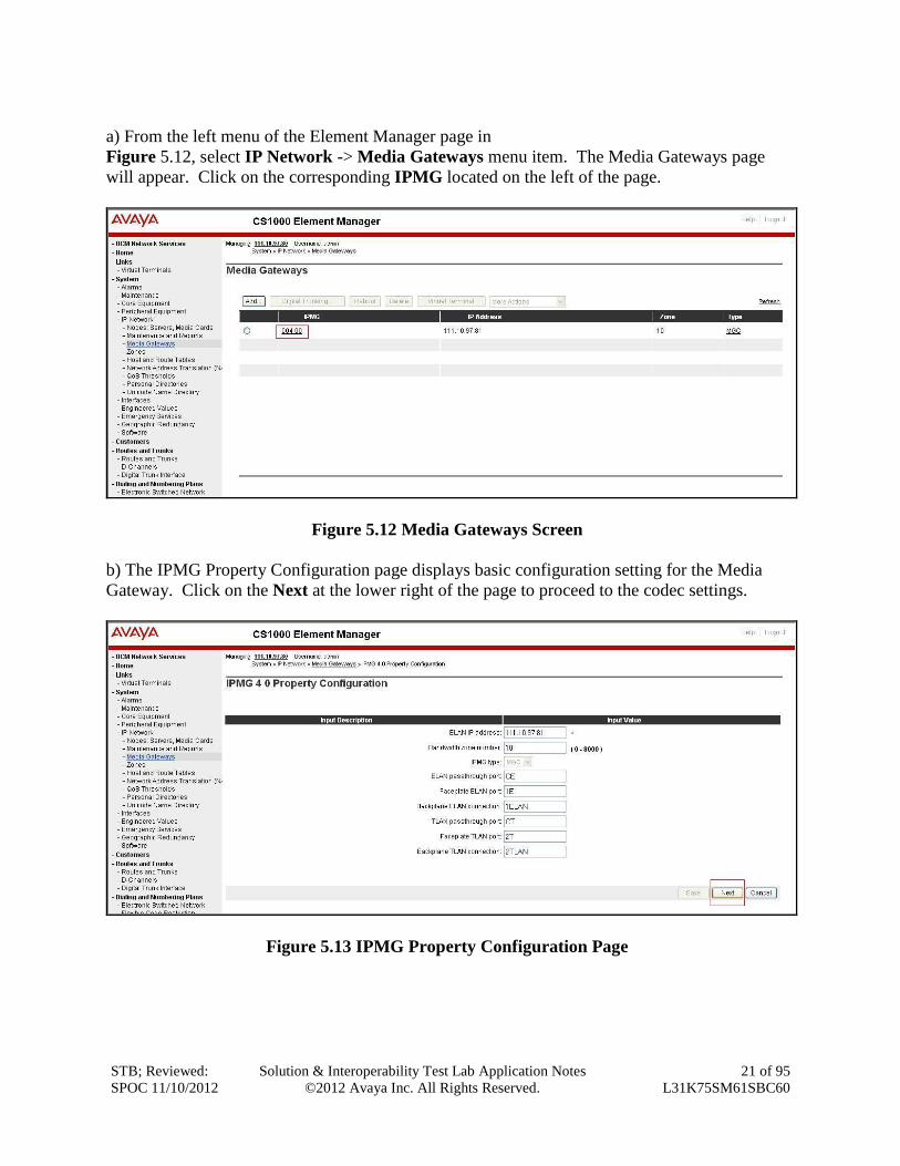
a) From the left menu of the Element Manager page in
Figure 5.12, select IP Network -> Media Gateways menu item. The Media Gateways page
will appear. Click on the corresponding IPMG located on the left of the page.
Figure 5.12 Media Gateways Screen
b) The IPMG Property Configuration page displays basic configuration setting for the Media
Gateway. Click on the Next at the lower right of the page to proceed to the codec settings.
Figure 5.13 IPMG Property Configuration Page
STB; Reviewed:
SPOC 11/10/2012
Solution & Interoperability Test Lab Application Notes
©2012 Avaya Inc. All Rights Reserved.
22 of 95
L31K75SM61SBC60
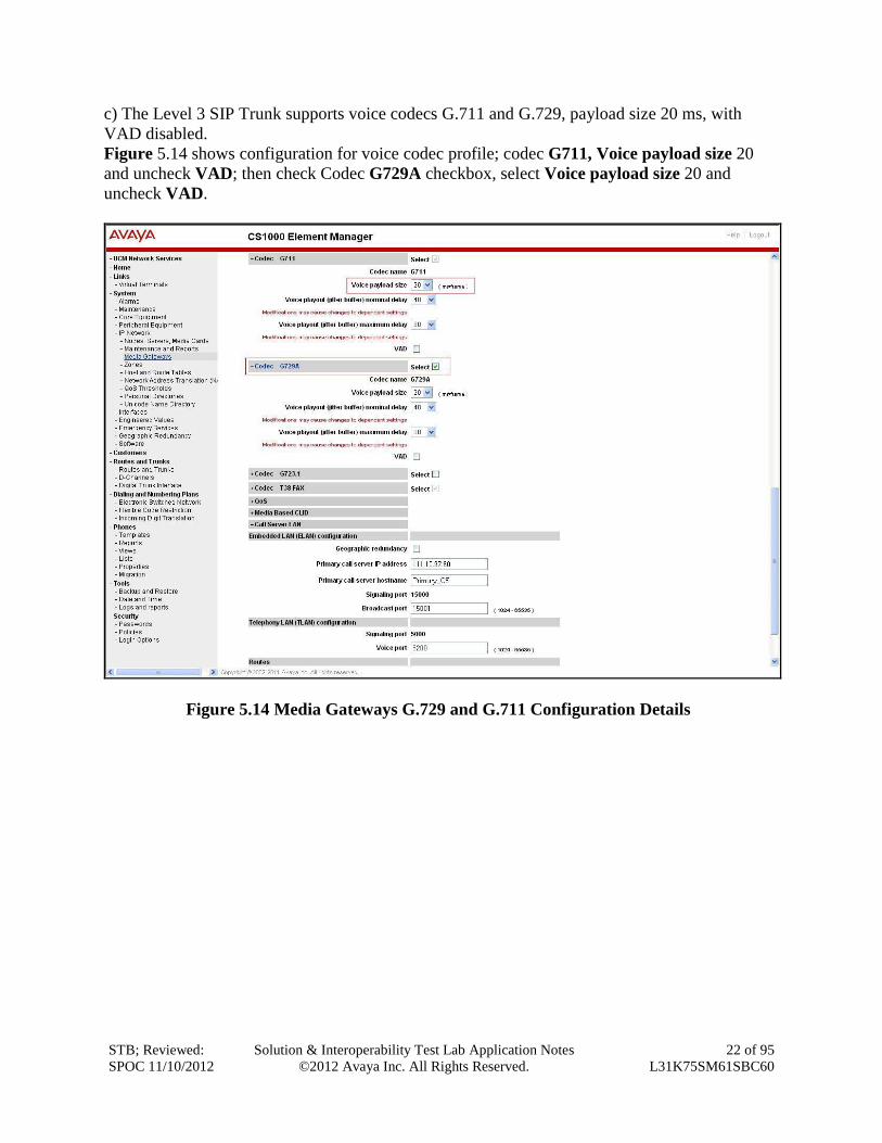
c) The Level 3 SIP Trunk supports voice codecs G.711 and G.729, payload size 20 ms, with
VAD disabled.
Figure 5.14 shows configuration for voice codec profile; codec G711, Voice payload size 20
and uncheck VAD; then check Codec G729A checkbox, select Voice payload size 20 and
uncheck VAD.
Figure 5.14 Media Gateways G.729 and G.711 Configuration Details
STB; Reviewed:
SPOC 11/10/2012
Solution & Interoperability Test Lab Application Notes
©2012 Avaya Inc. All Rights Reserved.
23 of 95
L31K75SM61SBC60
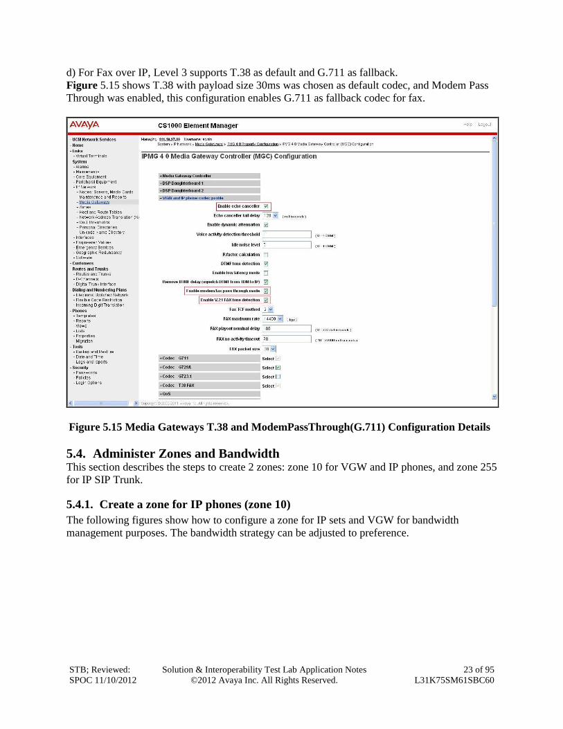
d) For Fax over IP, Level 3 supports T.38 as default and G.711 as fallback.
Figure 5.15 shows T.38 with payload size 30ms was chosen as default codec, and Modem Pass
Through was enabled, this configuration enables G.711 as fallback codec for fax.
Figure 5.15 Media Gateways T.38 and ModemPassThrough(G.711) Configuration Details
5.4. Administer Zones and Bandwidth This section describes the steps to create 2 zones: zone 10 for VGW and IP phones, and zone 255
for IP SIP Trunk.
5.4.1. Create a zone for IP phones (zone 10)
The following figures show how to configure a zone for IP sets and VGW for bandwidth
management purposes. The bandwidth strategy can be adjusted to preference.
STB; Reviewed:
SPOC 11/10/2012
Solution & Interoperability Test Lab Application Notes
©2012 Avaya Inc. All Rights Reserved.
24 of 95
L31K75SM61SBC60
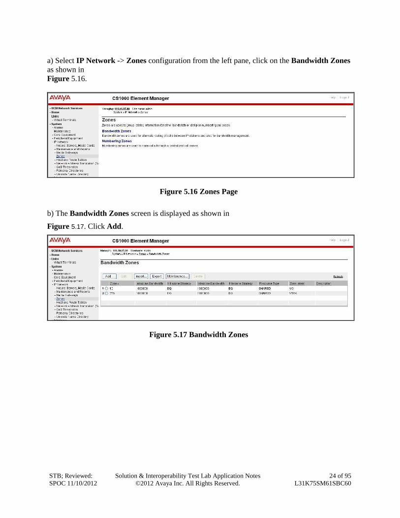
a) Select IP Network -> Zones configuration from the left pane, click on the Bandwidth Zones
as shown in
Figure 5.16.
Figure 5.16 Zones Page
b) The Bandwidth Zones screen is displayed as shown in
Figure 5.17. Click Add.
Figure 5.17 Bandwidth Zones
STB; Reviewed:
SPOC 11/10/2012
Solution & Interoperability Test Lab Application Notes
©2012 Avaya Inc. All Rights Reserved.
25 of 95
L31K75SM61SBC60
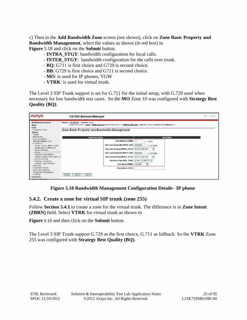
c) Then in the Add Bandwidth Zone screen (not shown), click on Zone Basic Property and
Bandwidth Management, select the values as shown (in red box) in
Figure 5.18 and click on the Submit button.
- INTRA_STGY: bandwidth configuration for local calls.
- INTER_STGY: bandwidth configuration for the calls over trunk.
- BQ: G711 is first choice and G729 is second choice.
- BB: G729 is first choice and G711 is second choice.
- MO: is used for IP phones, VGW
- VTRK: is used for virtual trunk.
The Level 3 SIP Trunk support is set for G.711 for the initial setup, with G.729 used when
necessary for low bandwidth test cases. So the MO Zone 10 was configured with Strategy Best
Quality (BQ).
Figure 5.18 Bandwidth Management Configuration Details– IP phone
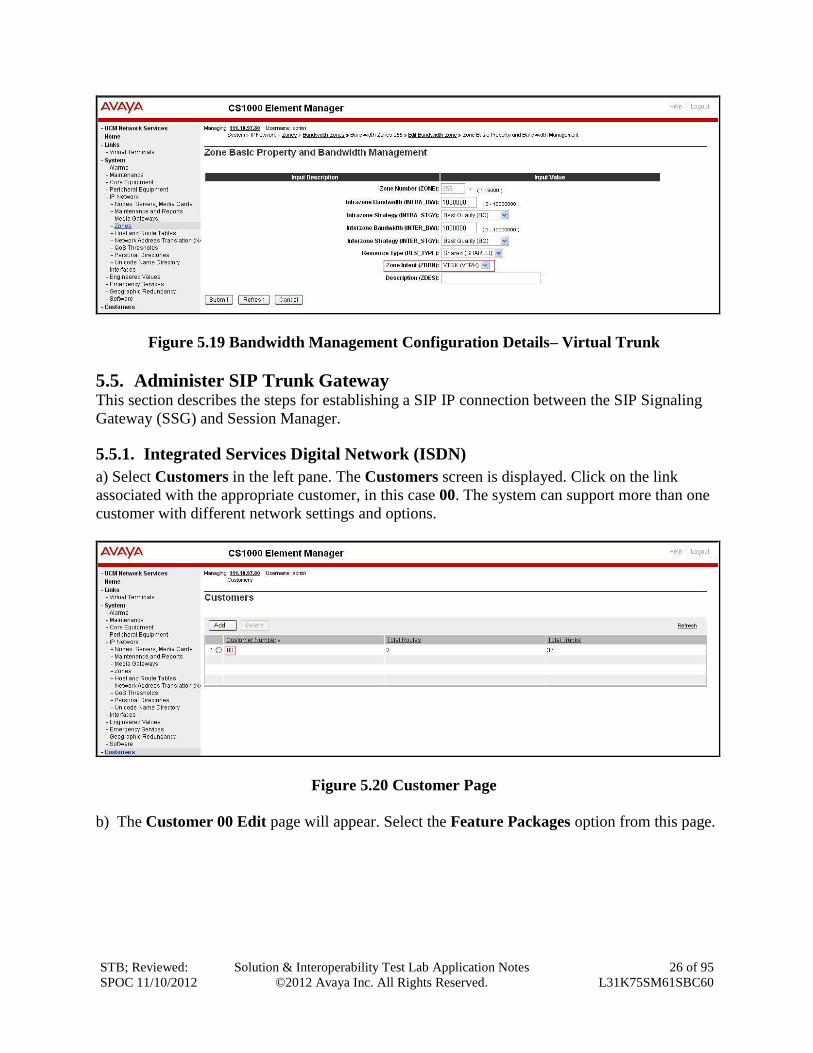
5.4.2. Create a zone for virtual SIP trunk (zone 255)
Follow Section 5.4.1 to create a zone for the virtual trunk. The difference is in Zone Intent
(ZBRN) field. Select VTRK for virtual trunk as shown in
Figure 5.19 and then click on the Submit button.
The Level 3 SIP Trunk support G.729 as the first choice, G.711 as fallback. So the VTRK Zone
255 was configured with Strategy Best Quality (BQ).
STB; Reviewed:
SPOC 11/10/2012
Solution & Interoperability Test Lab Application Notes
©2012 Avaya Inc. All Rights Reserved.
26 of 95
L31K75SM61SBC60
Figure 5.19 Bandwidth Management Configuration Details– Virtual Trunk
5.5. Administer SIP Trunk Gateway This section describes the steps for establishing a SIP IP connection between the SIP Signaling
Gateway (SSG) and Session Manager.
5.5.1. Integrated Services Digital Network (ISDN)
a) Select Customers in the left pane. The Customers screen is displayed. Click on the link
associated with the appropriate customer, in this case 00. The system can support more than one
customer with different network settings and options.
Figure 5.20 Customer Page
b) The Customer 00 Edit page will appear. Select the Feature Packages option from this page.
STB; Reviewed:
SPOC 11/10/2012
Solution & Interoperability Test Lab Application Notes
©2012 Avaya Inc. All Rights Reserved.
27 of 95
L31K75SM61SBC60
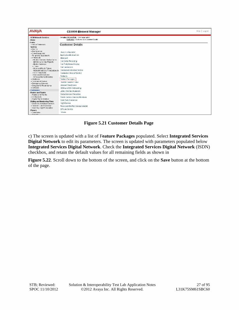
Figure 5.21 Customer Details Page
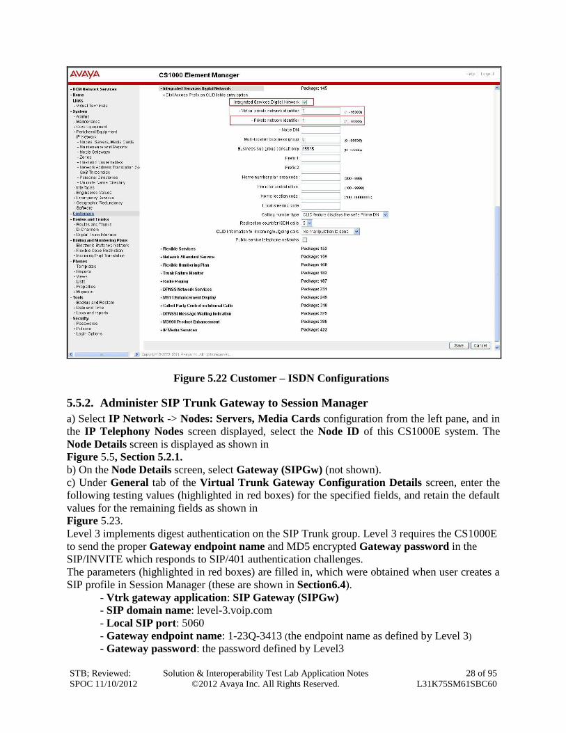
c) The screen is updated with a list of Feature Packages populated. Select Integrated Services
Digital Network to edit its parameters. The screen is updated with parameters populated below
Integrated Services Digital Network. Check the Integrated Services Digital Network (ISDN)
checkbox, and retain the default values for all remaining fields as shown in
Figure 5.22. Scroll down to the bottom of the screen, and click on the Save button at the bottom
of the page.
STB; Reviewed:
SPOC 11/10/2012
Solution & Interoperability Test Lab Application Notes
©2012 Avaya Inc. All Rights Reserved.
28 of 95
L31K75SM61SBC60
Figure 5.22 Customer – ISDN Configurations
5.5.2. Administer SIP Trunk Gateway to Session Manager
a) Select IP Network -> Nodes: Servers, Media Cards configuration from the left pane, and in
the IP Telephony Nodes screen displayed, select the Node ID of this CS1000E system. The
Node Details screen is displayed as shown in
Figure 5.5, Section 5.2.1.
b) On the Node Details screen, select Gateway (SIPGw) (not shown).
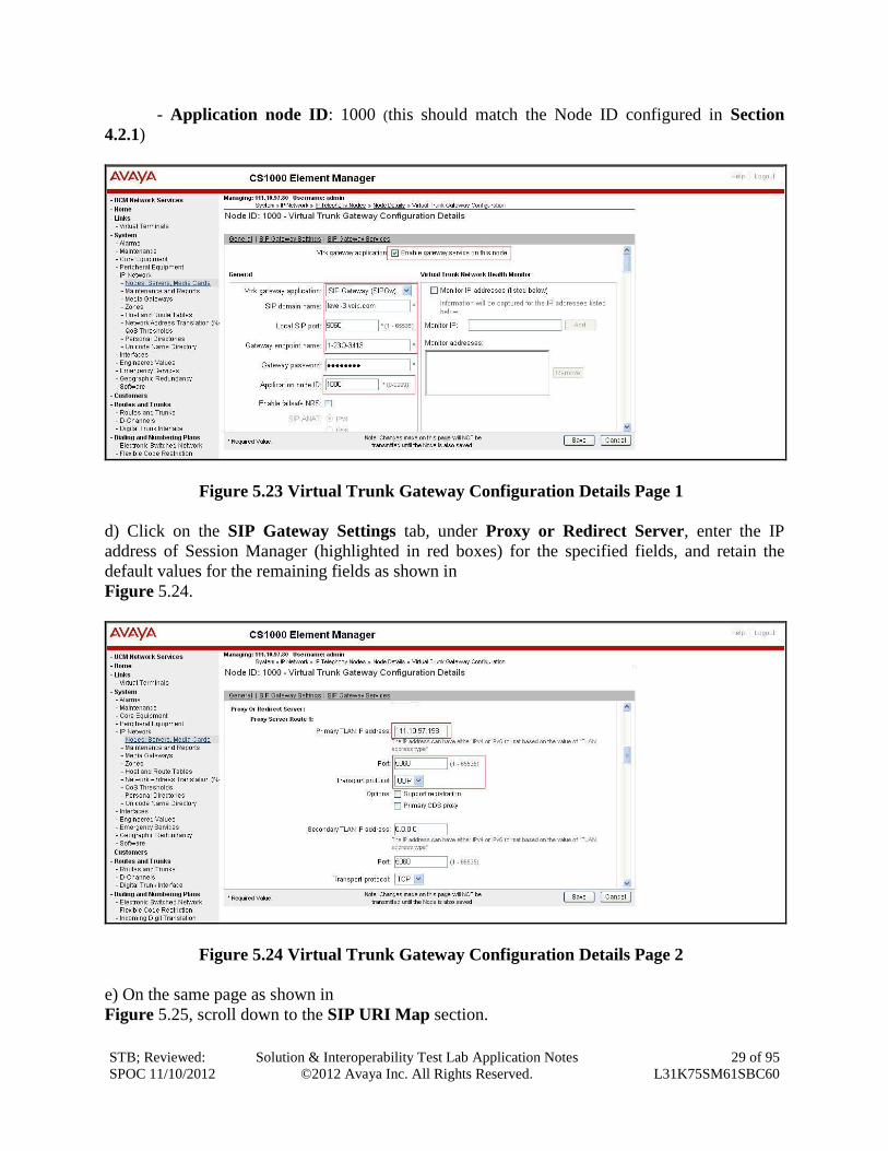
c) Under General tab of the Virtual Trunk Gateway Configuration Details screen, enter the
following testing values (highlighted in red boxes) for the specified fields, and retain the default
values for the remaining fields as shown in
Figure 5.23.
Level 3 implements digest authentication on the SIP Trunk group. Level 3 requires the CS1000E
to send the proper Gateway endpoint name and MD5 encrypted Gateway password in the
SIP/INVITE which responds to SIP/401 authentication challenges.
The parameters (highlighted in red boxes) are filled in, which were obtained when user creates a
SIP profile in Session Manager (these are shown in Section6.4).
- Vtrk gateway application: SIP Gateway (SIPGw)
- SIP domain name: level-3.voip.com
- Local SIP port: 5060
- Gateway endpoint name: 1-23Q-3413 (the endpoint name as defined by Level 3)
- Gateway password: the password defined by Level3
STB; Reviewed:
SPOC 11/10/2012
Solution & Interoperability Test Lab Application Notes
©2012 Avaya Inc. All Rights Reserved.
29 of 95
L31K75SM61SBC60
- Application node ID: 1000 (this should match the Node ID configured in Section
4.2.1)
Figure 5.23 Virtual Trunk Gateway Configuration Details Page 1
d) Click on the SIP Gateway Settings tab, under Proxy or Redirect Server, enter the IP
address of Session Manager (highlighted in red boxes) for the specified fields, and retain the
default values for the remaining fields as shown in
Figure 5.24.
Figure 5.24 Virtual Trunk Gateway Configuration Details Page 2
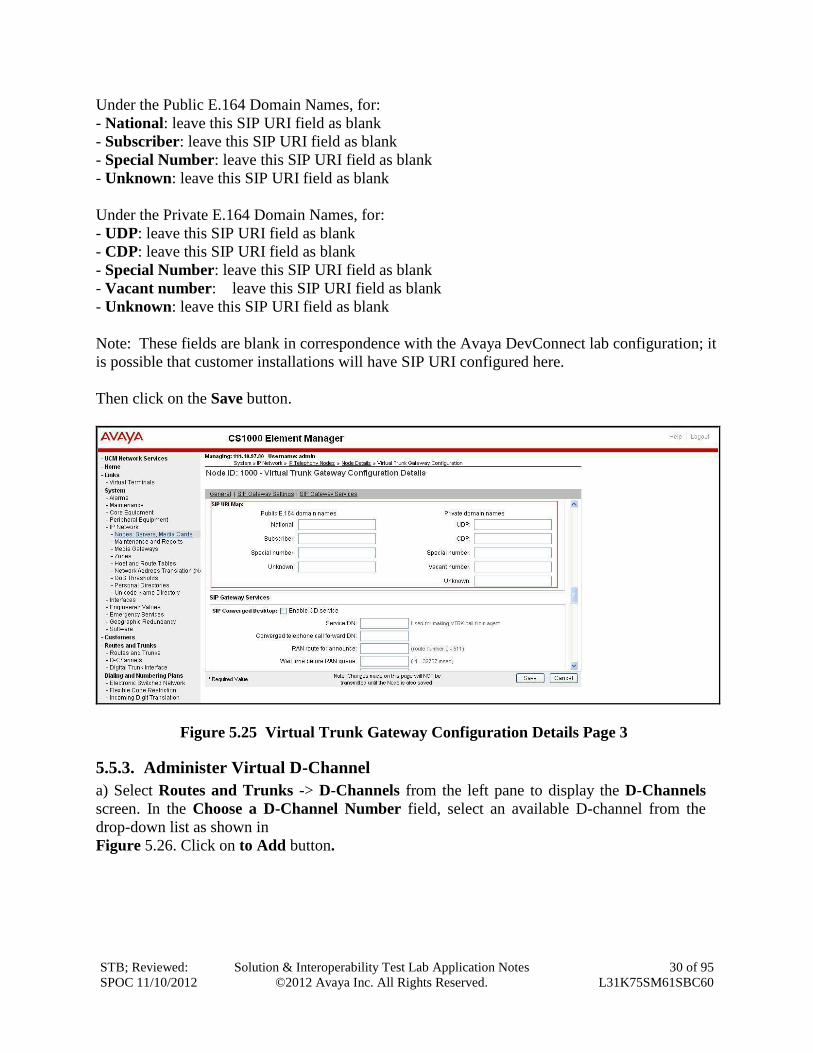
e) On the same page as shown in
Figure 5.25, scroll down to the SIP URI Map section.
STB; Reviewed:
SPOC 11/10/2012
Solution & Interoperability Test Lab Application Notes
©2012 Avaya Inc. All Rights Reserved.
30 of 95
L31K75SM61SBC60
Under the Public E.164 Domain Names, for:
- National: leave this SIP URI field as blank
- Subscriber: leave this SIP URI field as blank
- Special Number: leave this SIP URI field as blank
- Unknown: leave this SIP URI field as blank
Under the Private E.164 Domain Names, for:
- UDP: leave this SIP URI field as blank
- CDP: leave this SIP URI field as blank
- Special Number: leave this SIP URI field as blank
- Vacant number: leave this SIP URI field as blank
- Unknown: leave this SIP URI field as blank
Note: These fields are blank in correspondence with the Avaya DevConnect lab configuration; it
is possible that customer installations will have SIP URI configured here.
Then click on the Save button.
Figure 5.25 Virtual Trunk Gateway Configuration Details Page 3
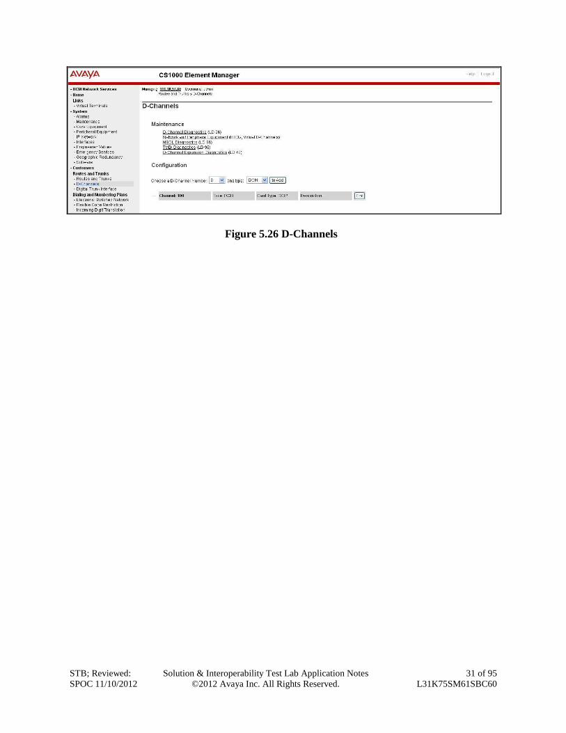
5.5.3. Administer Virtual D-Channel
a) Select Routes and Trunks -> D-Channels from the left pane to display the D-Channels
screen. In the Choose a D-Channel Number field, select an available D-channel from the
drop-down list as shown in
Figure 5.26. Click on to Add button.
STB; Reviewed:
SPOC 11/10/2012
Solution & Interoperability Test Lab Application Notes
©2012 Avaya Inc. All Rights Reserved.
31 of 95
L31K75SM61SBC60
Figure 5.26 D-Channels
STB; Reviewed:
SPOC 11/10/2012
Solution & Interoperability Test Lab Application Notes
©2012 Avaya Inc. All Rights Reserved.
32 of 95
L31K75SM61SBC60
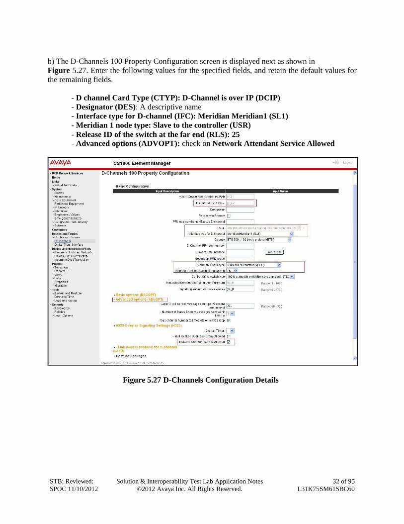
b) The D-Channels 100 Property Configuration screen is displayed next as shown in
Figure 5.27. Enter the following values for the specified fields, and retain the default values for
the remaining fields.
- D channel Card Type (CTYP): D-Channel is over IP (DCIP)
- Designator (DES): A descriptive name
- Interface type for D-channel (IFC): Meridian Meridian1 (SL1)
- Meridian 1 node type: Slave to the controller (USR)
- Release ID of the switch at the far end (RLS): 25
- Advanced options (ADVOPT): check on Network Attendant Service Allowed
Figure 5.27 D-Channels Configuration Details
STB; Reviewed:
SPOC 11/10/2012
Solution & Interoperability Test Lab Application Notes
©2012 Avaya Inc. All Rights Reserved.
33 of 95
L31K75SM61SBC60
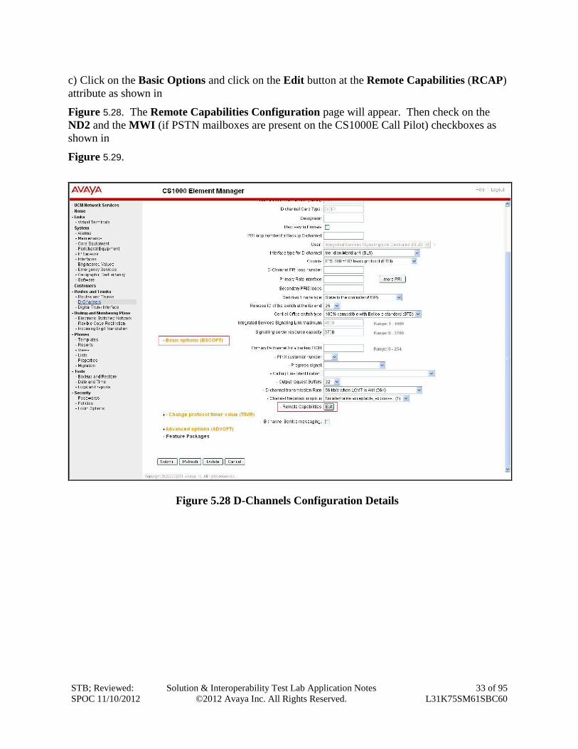
c) Click on the Basic Options and click on the Edit button at the Remote Capabilities (RCAP)
attribute as shown in
Figure 5.28. The Remote Capabilities Configuration page will appear. Then check on the
ND2 and the MWI (if PSTN mailboxes are present on the CS1000E Call Pilot) checkboxes as
shown in
Figure 5.29.
Figure 5.28 D-Channels Configuration Details
STB; Reviewed:
SPOC 11/10/2012
Solution & Interoperability Test Lab Application Notes
©2012 Avaya Inc. All Rights Reserved.
34 of 95
L31K75SM61SBC60
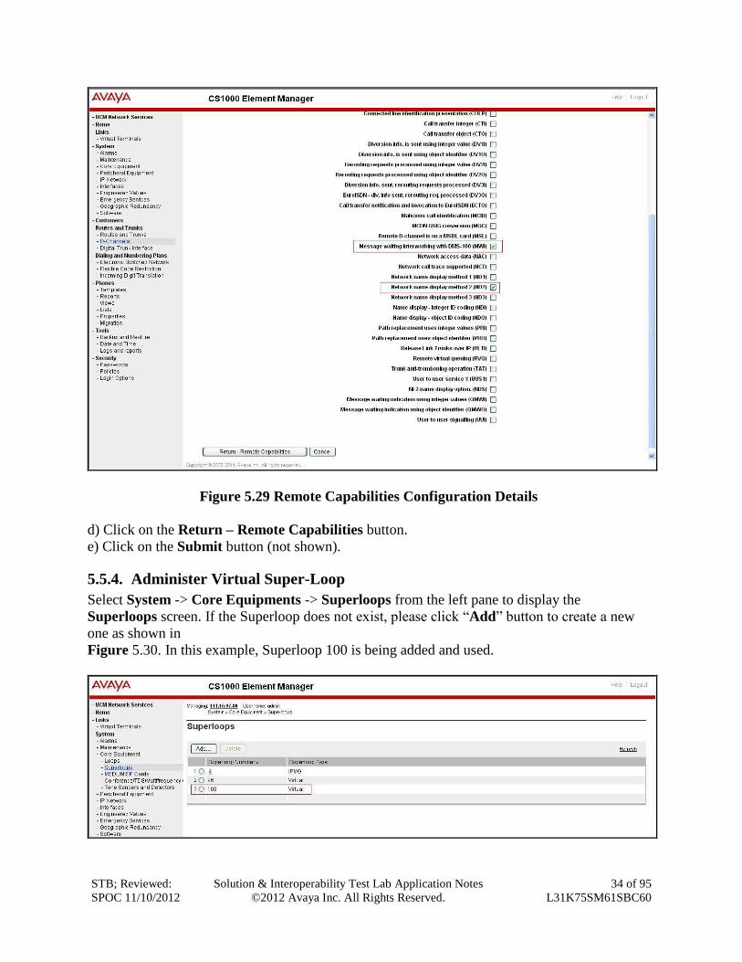
Figure 5.29 Remote Capabilities Configuration Details
d) Click on the Return – Remote Capabilities button.
e) Click on the Submit button (not shown).
5.5.4. Administer Virtual Super-Loop
Select System -> Core Equipments -> Superloops from the left pane to display the
Superloops screen. If the Superloop does not exist, please click “Add” button to create a new
one as shown in
Figure 5.30. In this example, Superloop 100 is being added and used.
STB; Reviewed:
SPOC 11/10/2012
Solution & Interoperability Test Lab Application Notes
©2012 Avaya Inc. All Rights Reserved.
35 of 95
L31K75SM61SBC60
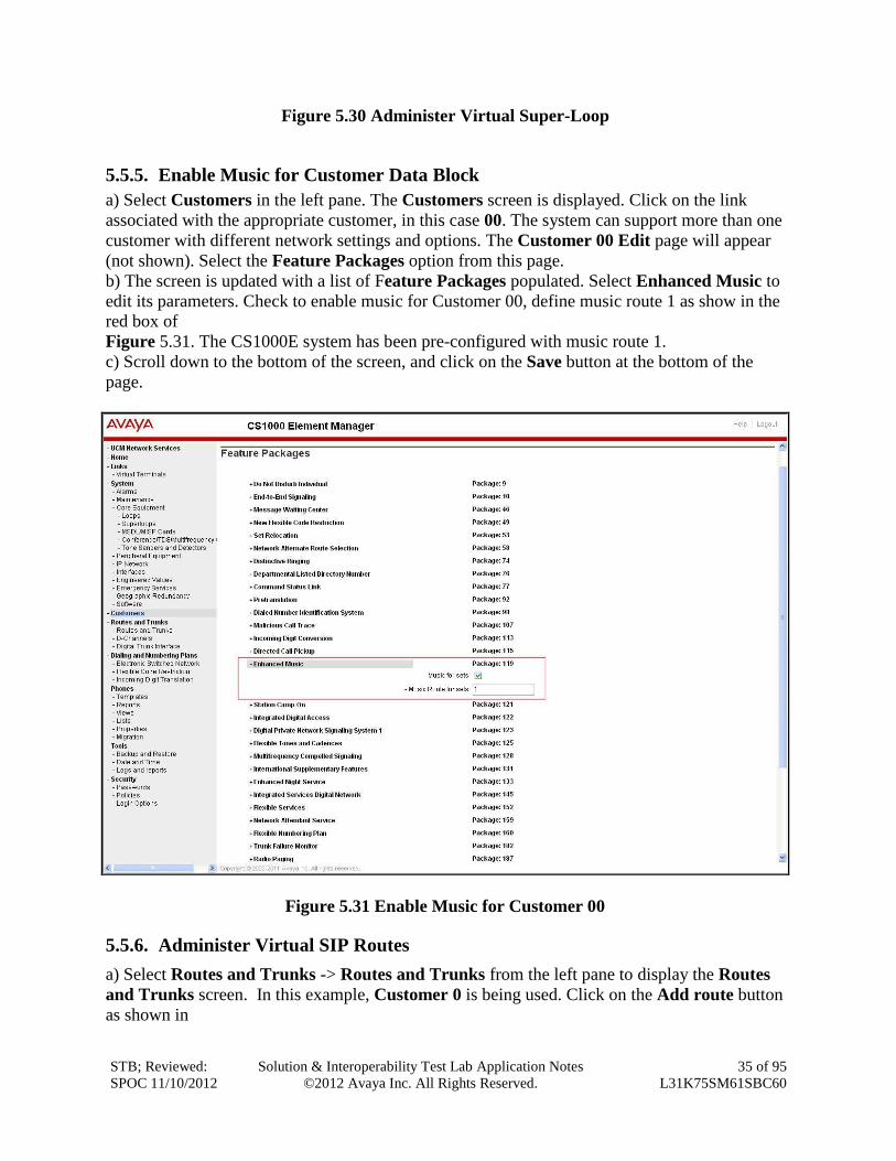
Figure 5.30 Administer Virtual Super-Loop
5.5.5. Enable Music for Customer Data Block
a) Select Customers in the left pane. The Customers screen is displayed. Click on the link
associated with the appropriate customer, in this case 00. The system can support more than one
customer with different network settings and options. The Customer 00 Edit page will appear
(not shown). Select the Feature Packages option from this page.
b) The screen is updated with a list of Feature Packages populated. Select Enhanced Music to
edit its parameters. Check to enable music for Customer 00, define music route 1 as show in the
red box of
Figure 5.31. The CS1000E system has been pre-configured with music route 1.
c) Scroll down to the bottom of the screen, and click on the Save button at the bottom of the
page.
Figure 5.31 Enable Music for Customer 00
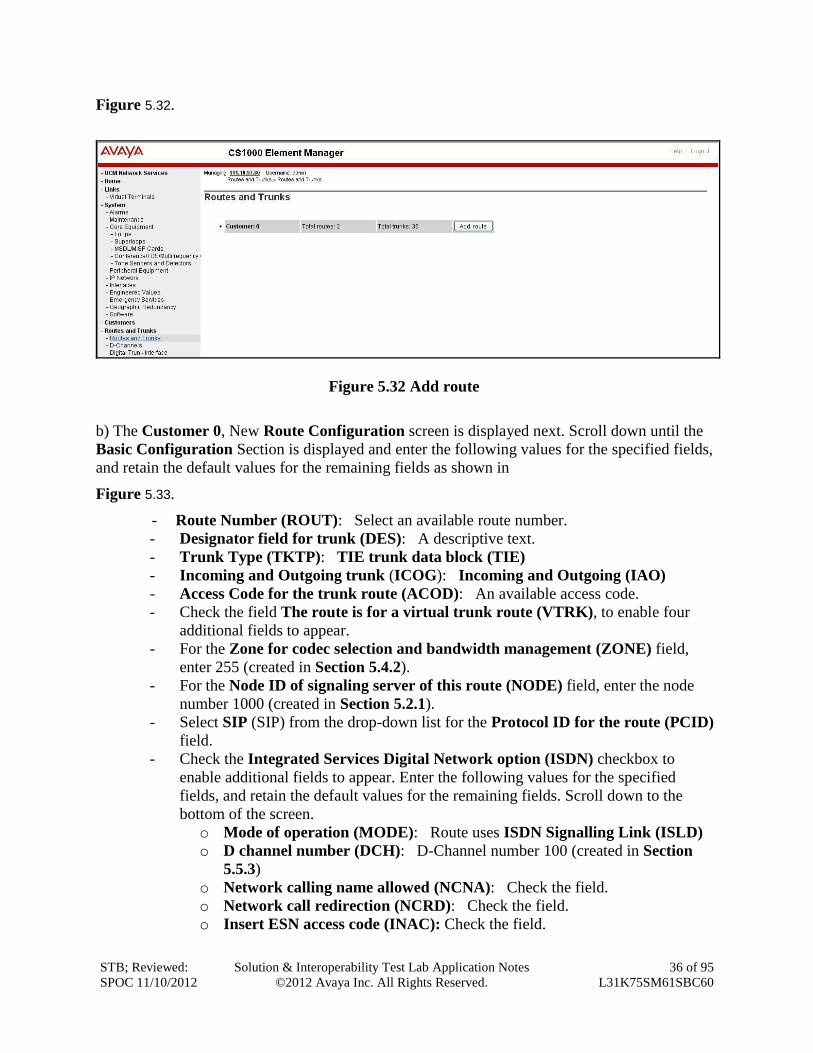
5.5.6. Administer Virtual SIP Routes
a) Select Routes and Trunks -> Routes and Trunks from the left pane to display the Routes
and Trunks screen. In this example, Customer 0 is being used. Click on the Add route button
as shown in
STB; Reviewed:
SPOC 11/10/2012
Solution & Interoperability Test Lab Application Notes
©2012 Avaya Inc. All Rights Reserved.
36 of 95
L31K75SM61SBC60
Figure 5.32.
Figure 5.32 Add route
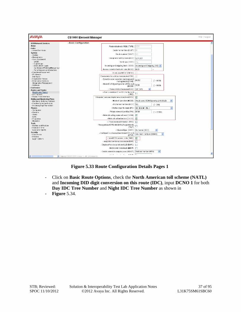
b) The Customer 0, New Route Configuration screen is displayed next. Scroll down until the
Basic Configuration Section is displayed and enter the following values for the specified fields,
and retain the default values for the remaining fields as shown in
Figure 5.33.
- Route Number (ROUT): Select an available route number.
- Designator field for trunk (DES): A descriptive text.
- Trunk Type (TKTP): TIE trunk data block (TIE)
- Incoming and Outgoing trunk (ICOG): Incoming and Outgoing (IAO)
- Access Code for the trunk route (ACOD): An available access code.
- Check the field The route is for a virtual trunk route (VTRK), to enable four
additional fields to appear.
- For the Zone for codec selection and bandwidth management (ZONE) field,
enter 255 (created in Section 5.4.2).
- For the Node ID of signaling server of this route (NODE) field, enter the node
number 1000 (created in Section 5.2.1).
- Select SIP (SIP) from the drop-down list for the Protocol ID for the route (PCID)
field.
- Check the Integrated Services Digital Network option (ISDN) checkbox to
enable additional fields to appear. Enter the following values for the specified
fields, and retain the default values for the remaining fields. Scroll down to the
bottom of the screen.
o Mode of operation (MODE): Route uses ISDN Signalling Link (ISLD)
o D channel number (DCH): D-Channel number 100 (created in Section
5.5.3)
o Network calling name allowed (NCNA): Check the field.
o Network call redirection (NCRD): Check the field.
o Insert ESN access code (INAC): Check the field.
STB; Reviewed:
SPOC 11/10/2012
Solution & Interoperability Test Lab Application Notes
©2012 Avaya Inc. All Rights Reserved.
37 of 95
L31K75SM61SBC60
Figure 5.33 Route Configuration Details Pages 1
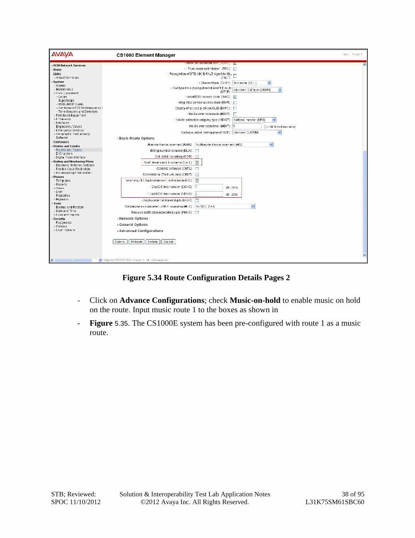
- Click on Basic Route Options, check the North American toll scheme (NATL)
and Incoming DID digit conversion on this route (IDC), input DCNO 1 for both
Day IDC Tree Number and Night IDC Tree Number as shown in
- Figure 5.34.
STB; Reviewed:
SPOC 11/10/2012
Solution & Interoperability Test Lab Application Notes
©2012 Avaya Inc. All Rights Reserved.
38 of 95
L31K75SM61SBC60
Figure 5.34 Route Configuration Details Pages 2
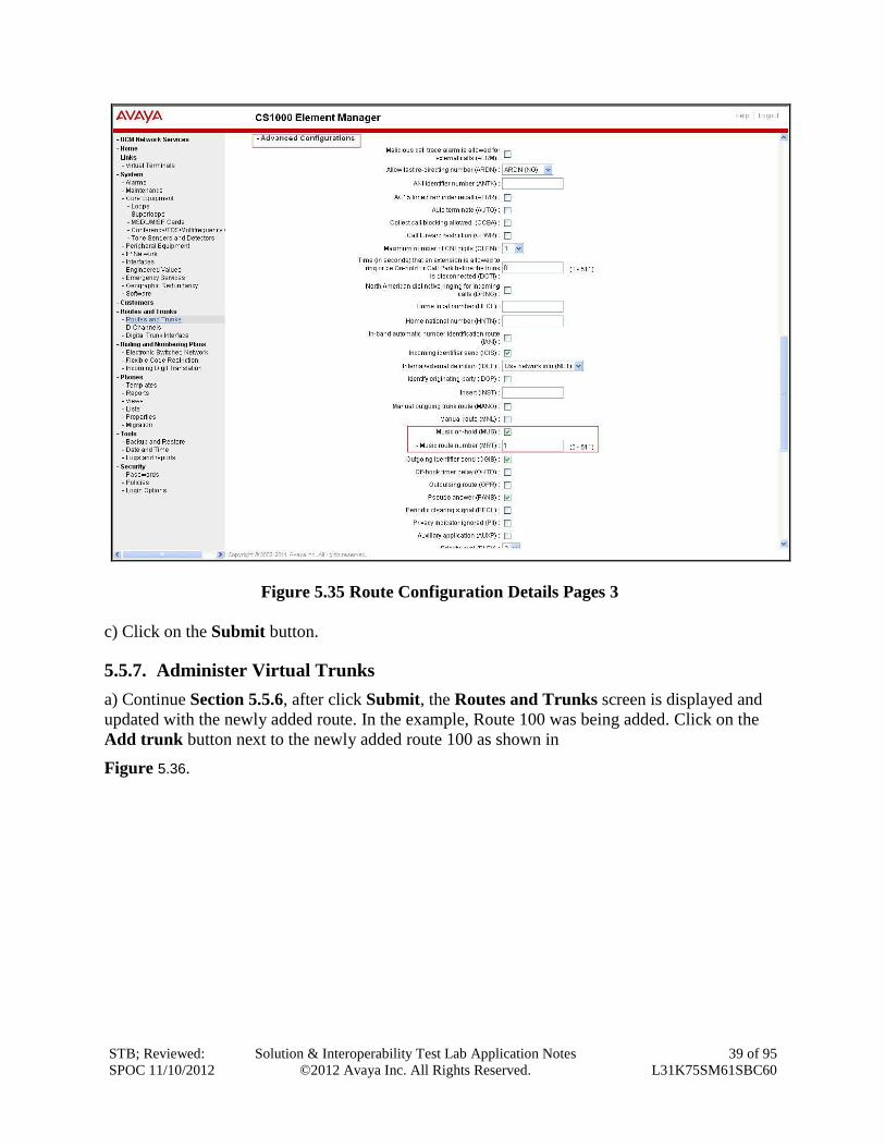
- Click on Advance Configurations; check Music-on-hold to enable music on hold
on the route. Input music route 1 to the boxes as shown in
- Figure 5.35. The CS1000E system has been pre-configured with route 1 as a music
route.
STB; Reviewed:
SPOC 11/10/2012
Solution & Interoperability Test Lab Application Notes
©2012 Avaya Inc. All Rights Reserved.
39 of 95
L31K75SM61SBC60
Figure 5.35 Route Configuration Details Pages 3
c) Click on the Submit button.
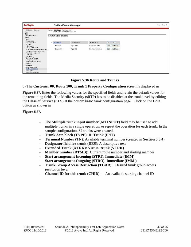
5.5.7. Administer Virtual Trunks
a) Continue Section 5.5.6, after click Submit, the Routes and Trunks screen is displayed and
updated with the newly added route. In the example, Route 100 was being added. Click on the
Add trunk button next to the newly added route 100 as shown in
Figure 5.36.
STB; Reviewed:
SPOC 11/10/2012
Solution & Interoperability Test Lab Application Notes
©2012 Avaya Inc. All Rights Reserved.
40 of 95
L31K75SM61SBC60
Figure 5.36 Route and Trunks
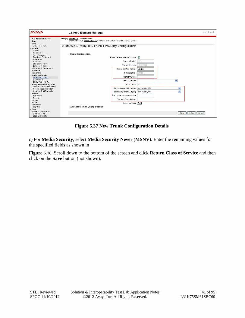
b) The Customer 00, Route 100, Trunk 1 Property Configuration screen is displayed in
Figure 5.37. Enter the following values for the specified fields and retain the default values for
the remaining fields. The Media Security (sRTP) has to be disabled at the trunk level by editing
the Class of Service (CLS) at the bottom basic trunk configuration page. Click on the Edit
button as shown in
Figure 5.37.
- The Multiple trunk input number (MTINPUT) field may be used to add
multiple trunks in a single operation, or repeat the operation for each trunk. In the
sample configuration, 32 trunks were created.
- Trunk data block (TYPE): IP Trunk (IPTI)
- Terminal Number (TN): Available terminal number (created in Section 5.5.4)
- Designator field for trunk (DES): A descriptive text
- Extended Trunk (XTRK): Virtual trunk (VTRK)
- Member number (RTMB): Current route number and starting member
- Start arrangement Incoming (STRI): Immediate (IMM)
- Start arrangement Outgoing (STRO): Immediate (IMM )
- Trunk Group Access Restriction (TGAR): Desired trunk group access
restriction level
- Channel ID for this trunk (CHID): An available starting channel ID
STB; Reviewed:
SPOC 11/10/2012
Solution & Interoperability Test Lab Application Notes
©2012 Avaya Inc. All Rights Reserved.
41 of 95
L31K75SM61SBC60
Figure 5.37 New Trunk Configuration Details
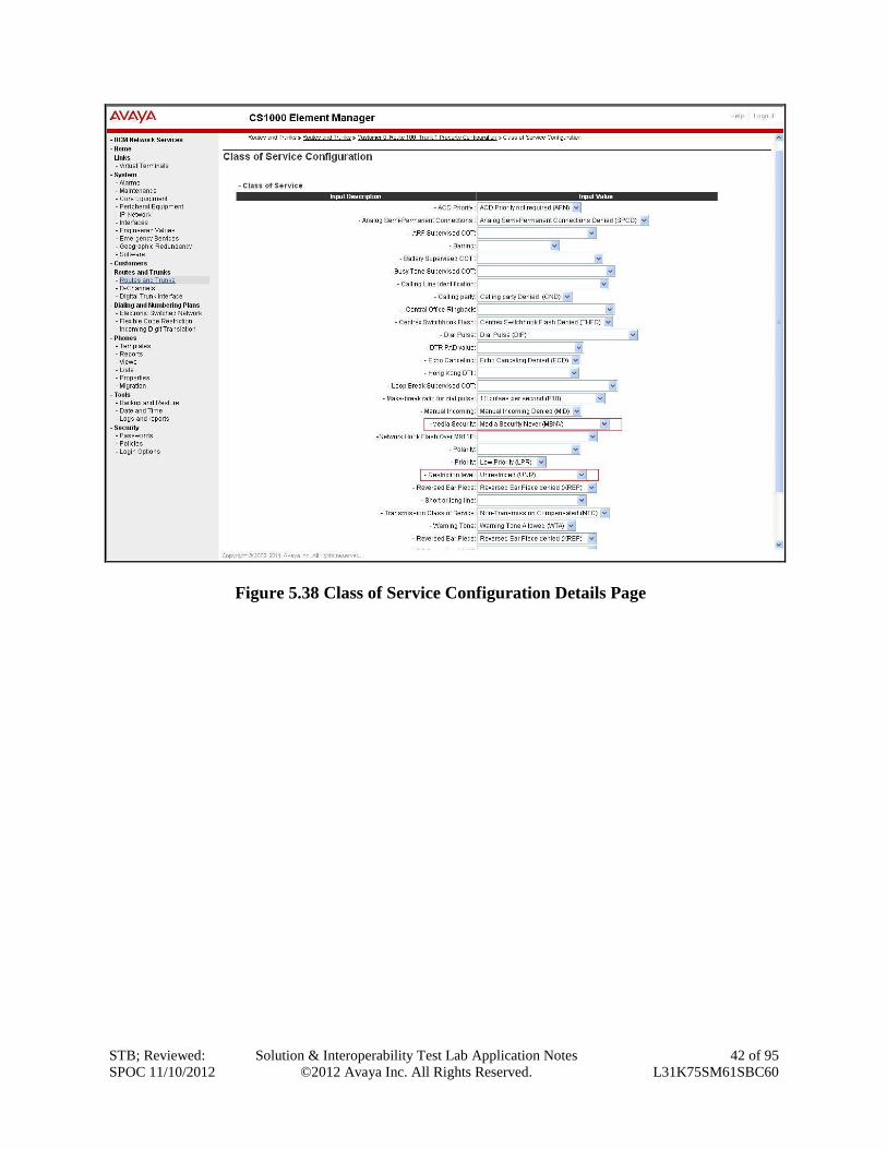
c) For Media Security, select Media Security Never (MSNV). Enter the remaining values for
the specified fields as shown in
Figure 5.38. Scroll down to the bottom of the screen and click Return Class of Service and then
click on the Save button (not shown).
STB; Reviewed:
SPOC 11/10/2012
Solution & Interoperability Test Lab Application Notes
©2012 Avaya Inc. All Rights Reserved.
42 of 95
L31K75SM61SBC60
Figure 5.38 Class of Service Configuration Details Page
STB; Reviewed:
SPOC 11/10/2012
Solution & Interoperability Test Lab Application Notes
©2012 Avaya Inc. All Rights Reserved.
43 of 95
L31K75SM61SBC60
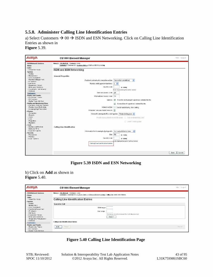
5.5.8. Administer Calling Line Identification Entries
a) Select Customers 00 ISDN and ESN Networking. Click on Calling Line Identification
Entries as shown in
Figure 5.39.
Figure 5.39 ISDN and ESN Networking
b) Click on Add as shown in
Figure 5.40.
Figure 5.40 Calling Line Identification Page
STB; Reviewed:
SPOC 11/10/2012
Solution & Interoperability Test Lab Application Notes
©2012 Avaya Inc. All Rights Reserved.
44 of 95
L31K75SM61SBC60
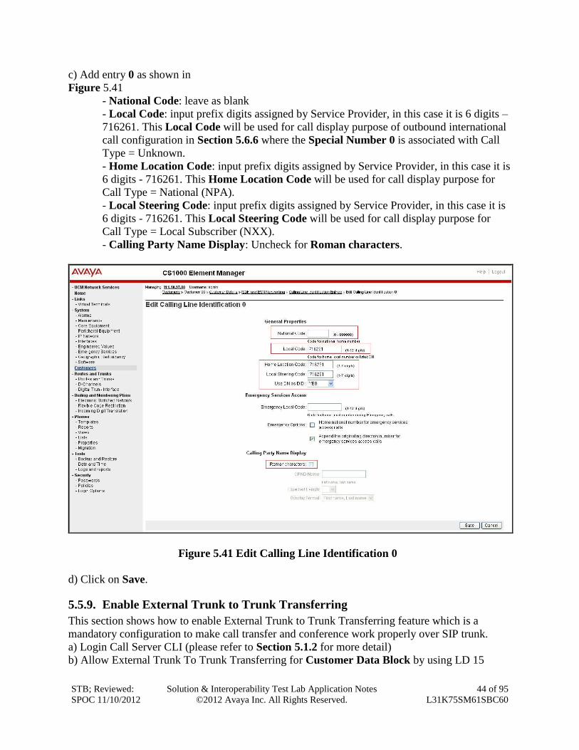
c) Add entry 0 as shown in
Figure 5.41
- National Code: leave as blank
- Local Code: input prefix digits assigned by Service Provider, in this case it is 6 digits –
716261. This Local Code will be used for call display purpose of outbound international
call configuration in Section 5.6.6 where the Special Number 0 is associated with Call
Type = Unknown.
- Home Location Code: input prefix digits assigned by Service Provider, in this case it is
6 digits - 716261. This Home Location Code will be used for call display purpose for
Call Type = National (NPA).
- Local Steering Code: input prefix digits assigned by Service Provider, in this case it is
6 digits - 716261. This Local Steering Code will be used for call display purpose for
Call Type = Local Subscriber (NXX).
- Calling Party Name Display: Uncheck for Roman characters.
Figure 5.41 Edit Calling Line Identification 0
d) Click on Save.
5.5.9. Enable External Trunk to Trunk Transferring
This section shows how to enable External Trunk to Trunk Transferring feature which is a
mandatory configuration to make call transfer and conference work properly over SIP trunk.
a) Login Call Server CLI (please refer to Section 5.1.2 for more detail)
b) Allow External Trunk To Trunk Transferring for Customer Data Block by using LD 15
STB; Reviewed:
SPOC 11/10/2012
Solution & Interoperability Test Lab Application Notes
©2012 Avaya Inc. All Rights Reserved.
45 of 95
L31K75SM61SBC60
>ld 15
CDB000
MEM AVAIL: (U/P): 35600176 USED U P: 8325631 954062 TOT: 44879869
DISK SPACE NEEDED: 1722 KBYTES
REQ: chg
TYPE: net
TYPE NET_DATA
CUST 0
OPT
…
TRNX yes
EXTT yes
…
5.6. Administer Dialing Plans
5.6.1. Define ESN Access Codes and Parameters (ESN)
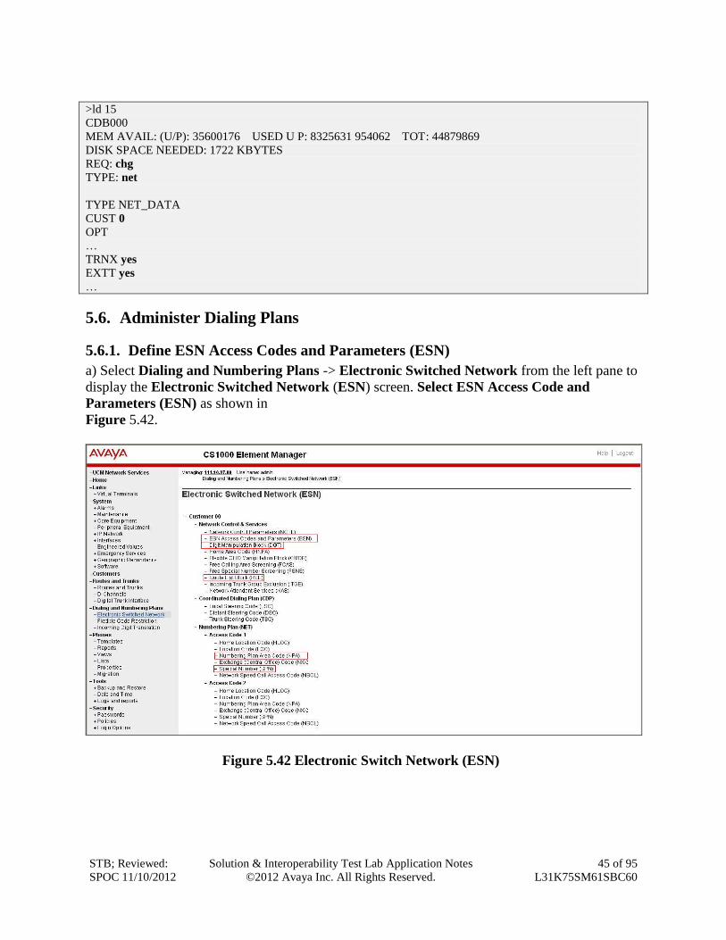
a) Select Dialing and Numbering Plans -> Electronic Switched Network from the left pane to
display the Electronic Switched Network (ESN) screen. Select ESN Access Code and
Parameters (ESN) as shown in
Figure 5.42.
Figure 5.42 Electronic Switch Network (ESN)
STB; Reviewed:
SPOC 11/10/2012
Solution & Interoperability Test Lab Application Notes
©2012 Avaya Inc. All Rights Reserved.
46 of 95
L31K75SM61SBC60
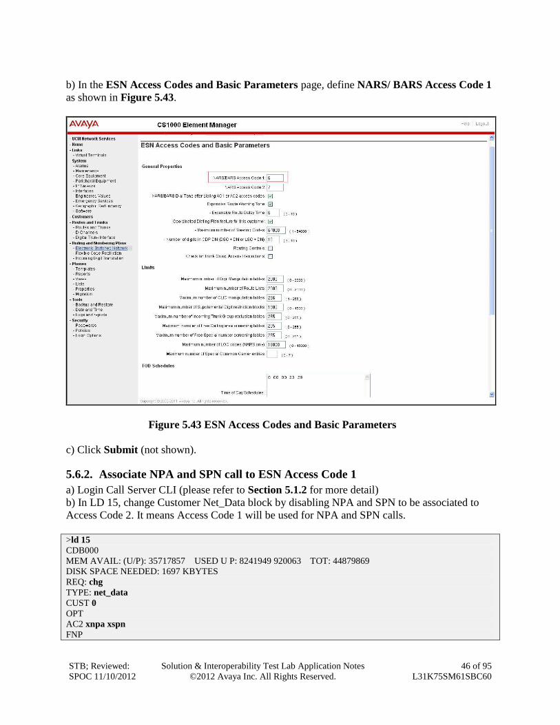
b) In the ESN Access Codes and Basic Parameters page, define NARS/ BARS Access Code 1
as shown in Figure 5.43.
Figure 5.43 ESN Access Codes and Basic Parameters
c) Click Submit (not shown).
5.6.2. Associate NPA and SPN call to ESN Access Code 1
a) Login Call Server CLI (please refer to Section 5.1.2 for more detail)
b) In LD 15, change Customer Net_Data block by disabling NPA and SPN to be associated to
Access Code 2. It means Access Code 1 will be used for NPA and SPN calls.
>ld 15
CDB000
MEM AVAIL: (U/P): 35717857 USED U P: 8241949 920063 TOT: 44879869
DISK SPACE NEEDED: 1697 KBYTES
REQ: chg
TYPE: net_data
CUST 0
OPT
AC2 xnpa xspn
FNP
STB; Reviewed:
SPOC 11/10/2012
Solution & Interoperability Test Lab Application Notes
©2012 Avaya Inc. All Rights Reserved.
47 of 95
L31K75SM61SBC60
CLID
ISDN
…
c) Verify Customer Net_Data block by using LD 21
>ld 21
PT1000
REQ: prt
TYPE: net
TYPE NET_DATA
CUST 0
TYPE NET_DATA
CUST 00
OPT RTA
AC1 INTL NPA SPN NXX LOC
AC2
FNP YES
…
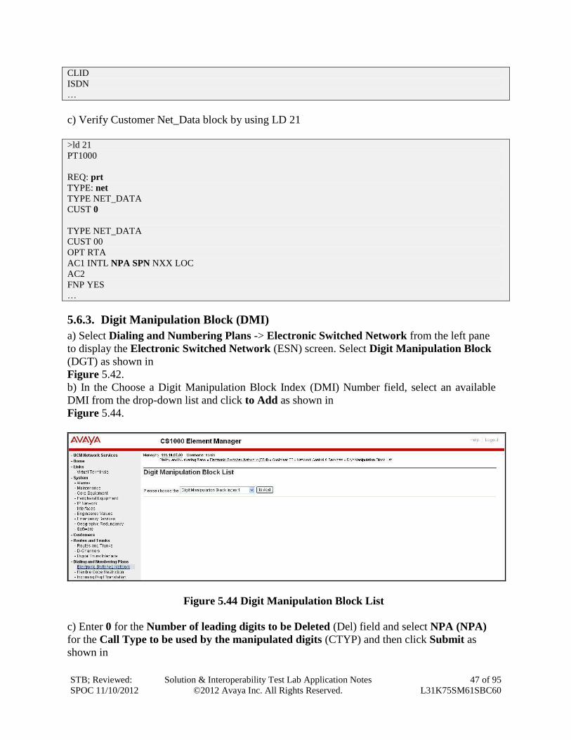
5.6.3. Digit Manipulation Block (DMI)
a) Select Dialing and Numbering Plans -> Electronic Switched Network from the left pane
to display the Electronic Switched Network (ESN) screen. Select Digit Manipulation Block
(DGT) as shown in
Figure 5.42. b) In the Choose a Digit Manipulation Block Index (DMI) Number field, select an available
DMI from the drop-down list and click to Add as shown in
Figure 5.44.
Figure 5.44 Digit Manipulation Block List
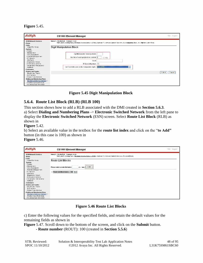
c) Enter 0 for the Number of leading digits to be Deleted (Del) field and select NPA (NPA)
for the Call Type to be used by the manipulated digits (CTYP) and then click Submit as
shown in
STB; Reviewed:
SPOC 11/10/2012
Solution & Interoperability Test Lab Application Notes
©2012 Avaya Inc. All Rights Reserved.
48 of 95
L31K75SM61SBC60
Figure 5.45.
Figure 5.45 Digit Manipulation Block
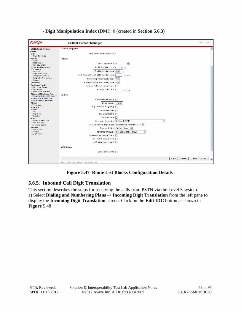
5.6.4. Route List Block (RLB) (RLB 100)
This section shows how to add a RLB associated with the DMI created in Section 5.6.3.
a) Select Dialing and Numbering Plans -> Electronic Switched Network from the left pane to
display the Electronic Switched Network (ESN) screen. Select Route List Block (RLB) as
shown in
Figure 5.42.
b) Select an available value in the textbox for the route list index and click on the “to Add”
button (in this case is 100) as shown in
Figure 5.46.
Figure 5.46 Route List Blocks
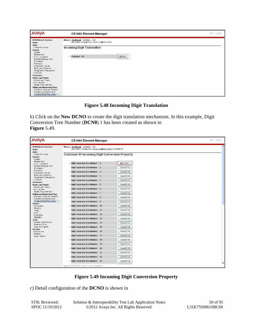
c) Enter the following values for the specified fields, and retain the default values for the
remaining fields as shown in
Figure 5.47. Scroll down to the bottom of the screen, and click on the Submit button.
- Route number (ROUT): 100 (created in Section 5.5.6)
STB; Reviewed:
SPOC 11/10/2012
Solution & Interoperability Test Lab Application Notes
©2012 Avaya Inc. All Rights Reserved.
49 of 95
L31K75SM61SBC60
- Digit Manipulation Index (DMI): 0 (created in Section 5.6.3)
Figure 5.47 Route List Blocks Configuration Details
5.6.5. Inbound Call Digit Translation
This section describes the steps for receiving the calls from PSTN via the Level 3 system.
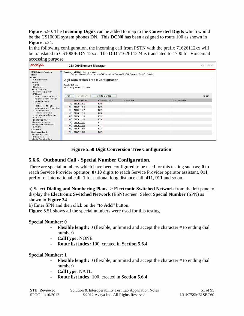
a) Select Dialing and Numbering Plans -> Incoming Digit Translation from the left pane to
display the Incoming Digit Translation screen. Click on the Edit IDC button as shown in
Figure 5.48
STB; Reviewed:
SPOC 11/10/2012
Solution & Interoperability Test Lab Application Notes
©2012 Avaya Inc. All Rights Reserved.
50 of 95
L31K75SM61SBC60
Figure 5.48 Incoming Digit Translation
b) Click on the New DCNO to create the digit translation mechanism. In this example, Digit
Conversion Tree Number (DCN0) 1 has been created as shown in
Figure 5.49.
Figure 5.49 Incoming Digit Conversion Property
c) Detail configuration of the DCNO is shown in
STB; Reviewed:
SPOC 11/10/2012
Solution & Interoperability Test Lab Application Notes
©2012 Avaya Inc. All Rights Reserved.
51 of 95
L31K75SM61SBC60
Figure 5.50. The Incoming Digits can be added to map to the Converted Digits which would
be the CS1000E system phones DN. This DCN0 has been assigned to route 100 as shown in
Figure 5.34.
In the following configuration, the incoming call from PSTN with the prefix 71626112xx will
be translated to CS1000E DN 12xx. The DID 7162611224 is translated to 1700 for Voicemail
accessing purpose.
Figure 5.50 Digit Conversion Tree Configuration
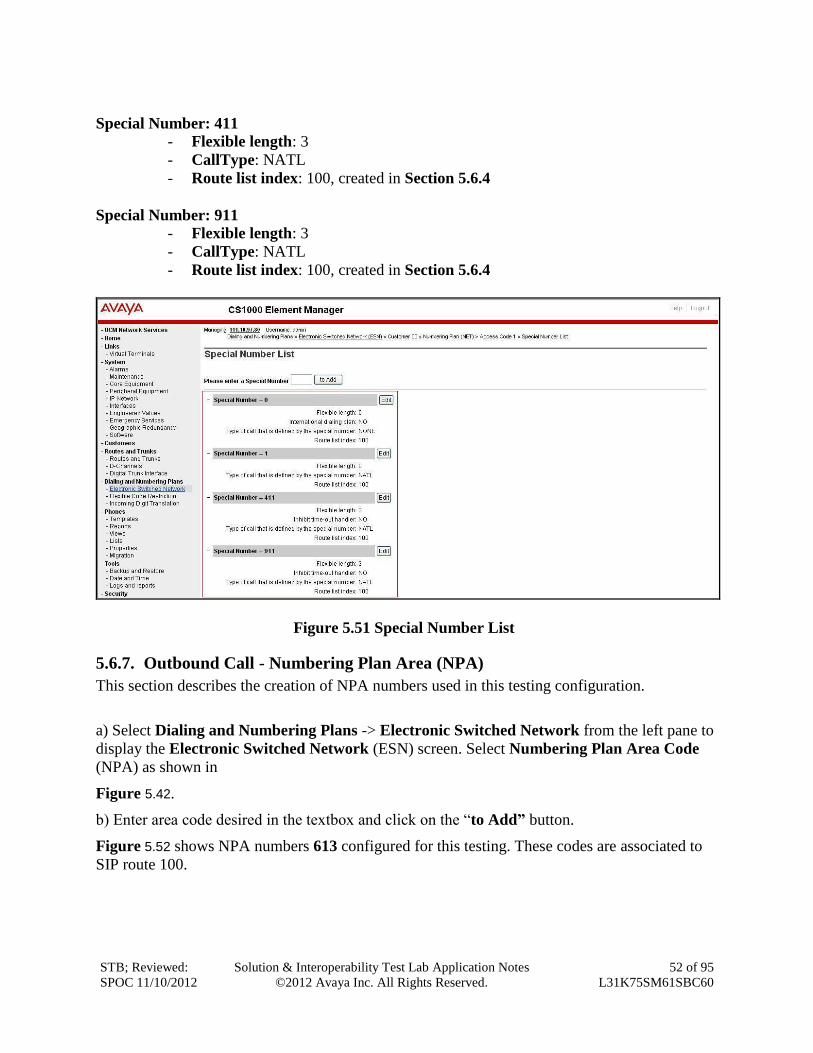
5.6.6. Outbound Call - Special Number Configuration.
There are special numbers which have been configured to be used for this testing such as; 0 to
reach Service Provider operator, 0+10 digits to reach Service Provider operator assistant, 011
prefix for international call, 1 for national long distance call, 411, 911 and so on.
a) Select Dialing and Numbering Plans -> Electronic Switched Network from the left pane to
display the Electronic Switched Network (ESN) screen. Select Special Number (SPN) as
shown in Figure 34.
b) Enter SPN and then click on the “to Add” button.
Figure 5.51 shows all the special numbers were used for this testing.
Special Number: 0
- Flexible length: 0 (flexible, unlimited and accept the character # to ending dial
number)
- CallType: NONE
- Route list index: 100, created in Section 5.6.4
Special Number: 1
- Flexible length: 0 (flexible, unlimited and accept the character # to ending dial
number)
- CallType: NATL
- Route list index: 100, created in Section 5.6.4
STB; Reviewed:
SPOC 11/10/2012
Solution & Interoperability Test Lab Application Notes
©2012 Avaya Inc. All Rights Reserved.
52 of 95
L31K75SM61SBC60
Special Number: 411
- Flexible length: 3
- CallType: NATL
- Route list index: 100, created in Section 5.6.4
Special Number: 911
- Flexible length: 3
- CallType: NATL
- Route list index: 100, created in Section 5.6.4
Figure 5.51 Special Number List
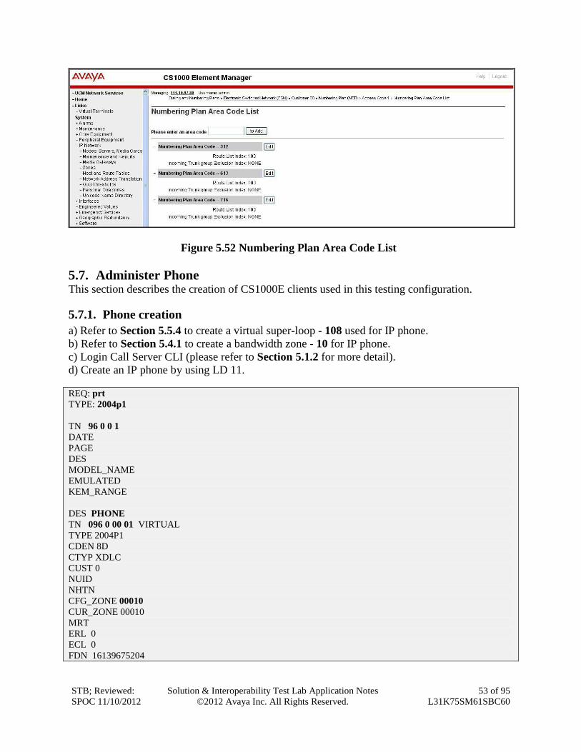
5.6.7. Outbound Call - Numbering Plan Area (NPA)
This section describes the creation of NPA numbers used in this testing configuration.
a) Select Dialing and Numbering Plans -> Electronic Switched Network from the left pane to
display the Electronic Switched Network (ESN) screen. Select Numbering Plan Area Code
(NPA) as shown in
Figure 5.42.
b) Enter area code desired in the textbox and click on the “to Add” button.
Figure 5.52 shows NPA numbers 613 configured for this testing. These codes are associated to
SIP route 100.
STB; Reviewed:
SPOC 11/10/2012
Solution & Interoperability Test Lab Application Notes
©2012 Avaya Inc. All Rights Reserved.
53 of 95
L31K75SM61SBC60
Figure 5.52 Numbering Plan Area Code List
5.7. Administer Phone This section describes the creation of CS1000E clients used in this testing configuration.
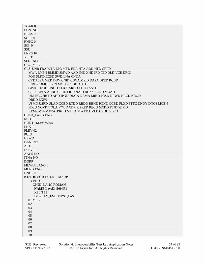
5.7.1. Phone creation
a) Refer to Section 5.5.4 to create a virtual super-loop - 108 used for IP phone.
b) Refer to Section 5.4.1 to create a bandwidth zone - 10 for IP phone.
c) Login Call Server CLI (please refer to Section 5.1.2 for more detail).
d) Create an IP phone by using LD 11.
REQ: prt
TYPE: 2004p1
TN 96 0 0 1
DATE
PAGE
DES
MODEL_NAME
EMULATED
KEM_RANGE
DES PHONE
TN 096 0 00 01 VIRTUAL
TYPE 2004P1
CDEN 8D
CTYP XDLC
CUST 0
NUID
NHTN
CFG_ZONE 00010
CUR_ZONE 00010
MRT
ERL 0
ECL 0
FDN 16139675204
STB; Reviewed:
SPOC 11/10/2012
Solution & Interoperability Test Lab Application Notes
©2012 Avaya Inc. All Rights Reserved.
54 of 95
L31K75SM61SBC60
TGAR 0
LDN NO
NCOS 0
SGRP 0
RNPG 0
SCI 0
SSU
LNRS 16
XLST
SFLT NO
CAC_MFC 0
CLS UNR FBA WTA LPR MTD FNA HTA ADD HFD CRPD
MWA LMPN RMMD SMWD AAD IMD XHD IRD NID OLD VCE DRG1
POD SLKD CCSD SWD LNA CNDA
CFTD SFA MRD DDV CNID CDCA MSID DAPA BFED RCBD
ICDD CDMD LLCN MCTD CLBD AUTU
GPUD DPUD DNDD CFXA ARHD CLTD ASCD
CPFA CPTA ABDD CFHD FICD NAID BUZZ AGRD MOAD
UDI RCC HBTD AHD IPND DDGA NAMA MIND PRSD NRWD NRCD NROD
DRDD EXR0
USMD USRD ULAD CCBD RTDD RBDD RBHD PGND OCBD FLXD FTTC DNDY DNO3 MCBN
FDSD NOVD VOLA VOUD CDMR PRED RECD MCDD T87D SBMD
KEM2 MSNV FRA PKCH MUTA MWTD DVLD CROD ELCD
CPND_LANG ENG
RCO 0
HUNT 16139675204
LHK 0
PLEV 02
PUID
UPWD
DANI NO
AST
IAPG 0
AACS NO
ITNA NO
DGRP
MLWU_LANG 0
MLNG ENG
DNDR 0
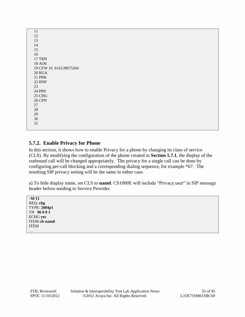
KEY 00 SCR 1216 0 MARP
CPND
CPND_LANG ROMAN
NAME Level3 i2004P1
XPLN 13
DISPLAY_FMT FIRST,LAST
01 MSB
02
03
04
05
06
07
08
09
10
STB; Reviewed:
SPOC 11/10/2012
Solution & Interoperability Test Lab Application Notes
©2012 Avaya Inc. All Rights Reserved.
55 of 95
L31K75SM61SBC60
11
12
13
14
15
16
17 TRN
18 AO6
19 CFW 16 616139675204
20 RGA
21 PRK
22 RNP
23
24 PRS
25 CHG
26 CPN
27
28
29
30
31
5.7.2. Enable Privacy for Phone
In this section, it shows how to enable Privacy for a phone by changing its class of service
(CLS). By modifying the configuration of the phone created in Section 5.7.1, the display of the
outbound call will be changed appropriately. The privacy for a single call can be done by
configuring per-call blocking and a corresponding dialing sequence, for example *67. The
resulting SIP privacy setting will be the same in either case.
a) To hide display name, set CLS to namd. CS1000E will include “Privacy:user” in SIP message
header before sending to Service Provider.
>ld 11
REQ: chg
TYPE: 2004p1
TN 96 0 0 1
ECHG yes
ITEM cls namd
ITEM
…
STB; Reviewed:
SPOC 11/10/2012
Solution & Interoperability Test Lab Application Notes
©2012 Avaya Inc. All Rights Reserved.
56 of 95
L31K75SM61SBC60
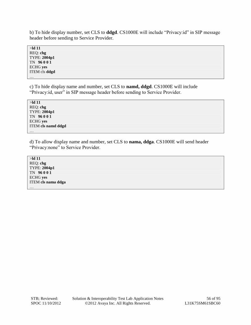
b) To hide display number, set CLS to ddgd. CS1000E will include “Privacy:id” in SIP message
header before sending to Service Provider.
>ld 11
REQ: chg
TYPE: 2004p1
TN 96 0 0 1
ECHG yes
ITEM cls ddgd
…
c) To hide display name and number, set CLS to namd, ddgd. CS1000E will include
“Privacy:id, user” in SIP message header before sending to Service Provider.
>ld 11
REQ: chg
TYPE: 2004p1
TN 96 0 0 1
ECHG yes
ITEM cls namd ddgd
…
d) To allow display name and number, set CLS to nama, ddga. CS1000E will send header
“Privacy:none” to Service Provider.
>ld 11
REQ: chg
TYPE: 2004p1
TN 96 0 0 1
ECHG yes
ITEM cls nama ddga
…
STB; Reviewed:
SPOC 11/10/2012
Solution & Interoperability Test Lab Application Notes
©2012 Avaya Inc. All Rights Reserved.
57 of 95
L31K75SM61SBC60
5.7.3. Enable Call Forward for Phone
In this section, it shows how to configure Call Forward feature at the system level and phone
level.
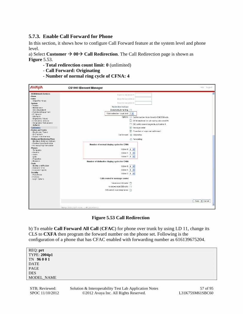
a) Select Customer 00 Call Redirection. The Call Redirection page is shown as
Figure 5.53.
- Total redirection count limit: 0 (unlimited)
- Call Forward: Originating
- Number of normal ring cycle of CFNA: 4
Figure 5.53 Call Redirection
b) To enable Call Forward All Call (CFAC) for phone over trunk by using LD 11, change its
CLS to CXFA then program the forward number on the phone set. Following is the
configuration of a phone that has CFAC enabled with forwarding number as 616139675204.
REQ: prt
TYPE: 2004p1
TN 96 0 0 1
DATE
PAGE
DES
MODEL_NAME
STB; Reviewed:
SPOC 11/10/2012
Solution & Interoperability Test Lab Application Notes
©2012 Avaya Inc. All Rights Reserved.
58 of 95
L31K75SM61SBC60
EMULATED
DES PHONE
TN 96 0 00 01 VIRTUAL
TYPE 2004P1
…
CLS UNR FBA WTA LPR MTD FNA HTA TDD HFD CRPD
MWA LMPN RMMD SMWD AAD IMD XHD IRD NID OLD VCE DRG1
POD SLKD CCSD SWD LNA CNDA
CFTD SFA MRD DDV CNID CDCA MSID DAPA BFED RCBD
ICDA CDMA LLCN MCTD CLBD AUTU
GPUD DPUD DNDD CFXA ARHD CLTD ASCD
…
19 CFW 16 616139675204
…
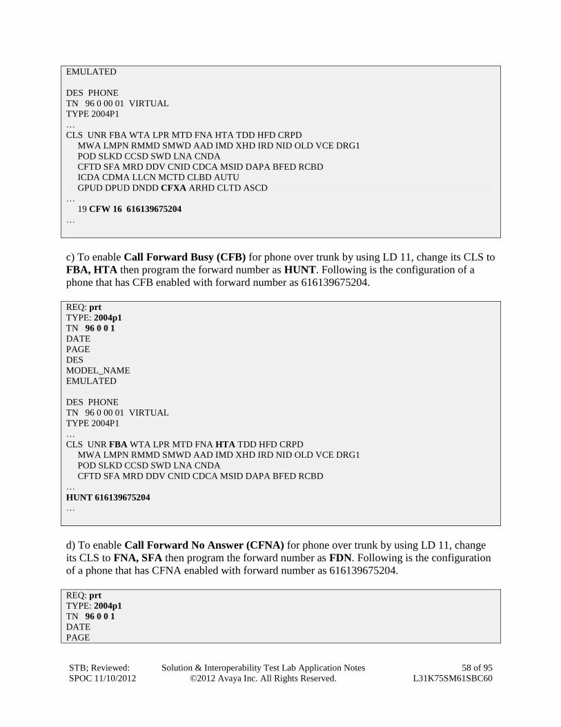
c) To enable Call Forward Busy (CFB) for phone over trunk by using LD 11, change its CLS to
FBA, HTA then program the forward number as HUNT. Following is the configuration of a
phone that has CFB enabled with forward number as 616139675204.
REQ: prt
TYPE: 2004p1
TN 96 0 0 1
DATE
PAGE
DES
MODEL_NAME
EMULATED
DES PHONE
TN 96 0 00 01 VIRTUAL
TYPE 2004P1
…
CLS UNR FBA WTA LPR MTD FNA HTA TDD HFD CRPD
MWA LMPN RMMD SMWD AAD IMD XHD IRD NID OLD VCE DRG1
POD SLKD CCSD SWD LNA CNDA
CFTD SFA MRD DDV CNID CDCA MSID DAPA BFED RCBD
…
HUNT 616139675204 …
d) To enable Call Forward No Answer (CFNA) for phone over trunk by using LD 11, change
its CLS to FNA, SFA then program the forward number as FDN. Following is the configuration
of a phone that has CFNA enabled with forward number as 616139675204.
REQ: prt
TYPE: 2004p1
TN 96 0 0 1
DATE
PAGE
STB; Reviewed:
SPOC 11/10/2012
Solution & Interoperability Test Lab Application Notes
©2012 Avaya Inc. All Rights Reserved.
59 of 95
L31K75SM61SBC60
DES
MODEL_NAME
EMULATED
DES PHONE
TN 96 0 00 01 VIRTUAL
TYPE 2004P1
…
FDN 616139675204
…
CLS UNR FBA WTA LPR MTD FNA HTA TDD HFD CRPD
MWA LMPN RMMD SMWD AAD IMD XHD IRD NID OLD VCE DRG1
POD SLKD CCSD SWD LNA CNDA
CFTD SFA MRD DDV CNID CDCA MSID DAPA BFED RCBD
…
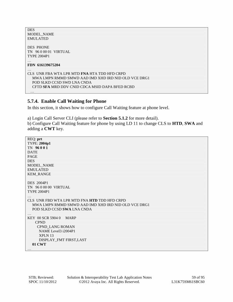
5.7.4. Enable Call Waiting for Phone
In this section, it shows how to configure Call Waiting feature at phone level.
a) Login Call Server CLI (please refer to Section 5.1.2 for more detail).
b) Configure Call Waiting feature for phone by using LD 11 to change CLS to HTD, SWA and
adding a CWT key.
REQ: prt
TYPE: 2004p1
TN 96 0 0 1
DATE
PAGE
DES
MODEL_NAME
EMULATED
KEM_RANGE
DES 2004P1
TN 96 0 00 00 VIRTUAL
TYPE 2004P1
…
CLS UNR FBD WTA LPR MTD FNA HTD TDD HFD CRPD
MWA LMPN RMMD SMWD AAD IMD XHD IRD NID OLD VCE DRG1
POD SLKD CCSD SWA LNA CNDA
…
KEY 00 SCR 5904 0 MARP
CPND
CPND_LANG ROMAN
NAME Level3 i2004P1
XPLN 13
DISPLAY_FMT FIRST,LAST
01 CWT
…
STB; Reviewed:
SPOC 11/10/2012
Solution & Interoperability Test Lab Application Notes
©2012 Avaya Inc. All Rights Reserved.
60 of 95
L31K75SM61SBC60
6. Administer Avaya Aura® Session Manager In this section, it shows how to configure the routing on Session Manager. It is assumed that the
Session Manager has been successfully deployed and connected to System Manager. The System
Manager is the web interface to configure the Session Manager.
6.1. Create a SIP domain name This section shows how to create a new SIP domain name for this test configuration. The Session
Manager uses this domain name to route the call from Level 3 to CS1000E and vice versa.
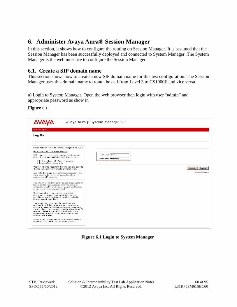
a) Login to System Manager. Open the web browser then login with user “admin” and
appropriate password as show in
Figure 6.1.
Figure 6.1 Login to System Manager
STB; Reviewed:
SPOC 11/10/2012
Solution & Interoperability Test Lab Application Notes
©2012 Avaya Inc. All Rights Reserved.
61 of 95
L31K75SM61SBC60
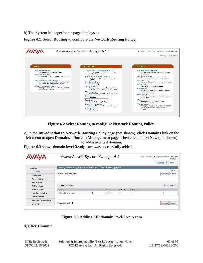
b) The System Manager home page displays as
Figure 6.2. Select Routing to configure the Network Routing Policy.
Figure 6.2 Select Routing to configure Network Routing Policy
c) In the Introduction to Network Routing Policy page (not shown), click Domains link on the
left menu to open Domains - Domain Management page. Then click button New (not shown)
to add a new test domain.
Figure 6.3 shows domain level-3.voip.com was successfully added.
Figure 6.3 Adding SIP domain level-3.voip.com
d) Click Commit.
STB; Reviewed:
SPOC 11/10/2012
Solution & Interoperability Test Lab Application Notes
©2012 Avaya Inc. All Rights Reserved.
62 of 95
L31K75SM61SBC60
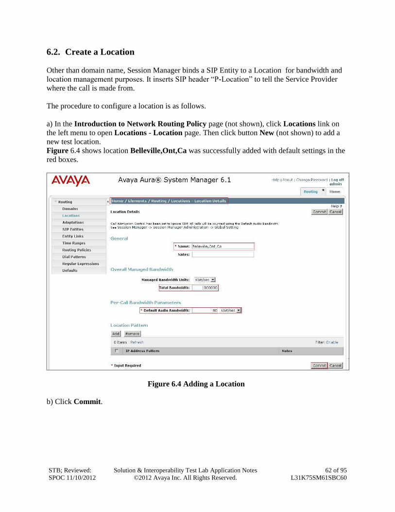
6.2. Create a Location
Other than domain name, Session Manager binds a SIP Entity to a Location for bandwidth and
location management purposes. It inserts SIP header “P-Location” to tell the Service Provider
where the call is made from.
The procedure to configure a location is as follows.
a) In the Introduction to Network Routing Policy page (not shown), click Locations link on
the left menu to open Locations - Location page. Then click button New (not shown) to add a
new test location.
Figure 6.4 shows location Belleville,Ont,Ca was successfully added with default settings in the
red boxes.
Figure 6.4 Adding a Location
b) Click Commit.
STB; Reviewed:
SPOC 11/10/2012
Solution & Interoperability Test Lab Application Notes
©2012 Avaya Inc. All Rights Reserved.
63 of 95
L31K75SM61SBC60
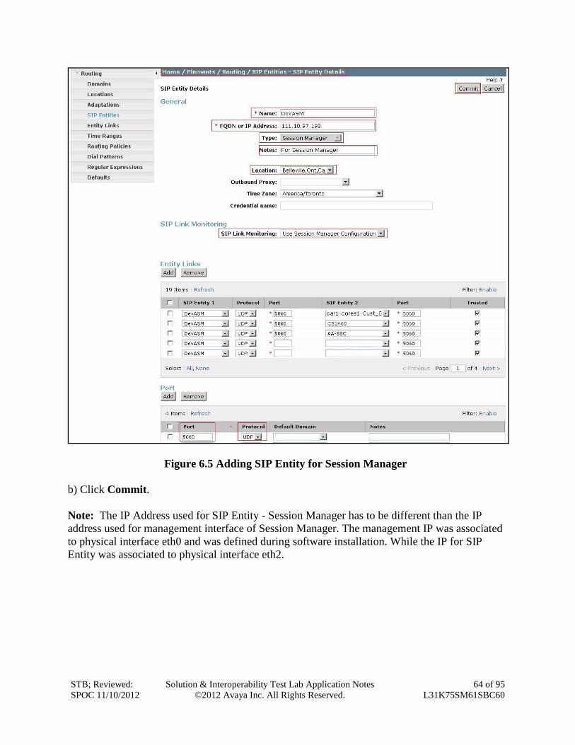
6.3. Create SIP Entity for Session Manager
This section shows how to configure System Manager to add a SIP Entity for Session Manager
as a static gateway.
a) In the Introduction to Network Routing Policy page (not shown), click SIP Entities link on
the left menu to open SIP Entities – SIP Entities page. Then click button New (not shown) to
add a new entity for Session Manager.
Figure 6.5 shows entity DevASM was successfully added. The Session Manager was configured
to use transport protocol UDP with port 5060.
- Name: DevASM
- FQDN or IP Address: 111.10.97.198
- Type: Session Manager
- Location: Belleville,Ont,Ca
- Port: 5060, Protocol: UDP
- SIP Link Monitoring: Use Session Manager Configuration
STB; Reviewed:
SPOC 11/10/2012
Solution & Interoperability Test Lab Application Notes
©2012 Avaya Inc. All Rights Reserved.
64 of 95
L31K75SM61SBC60
Figure 6.5 Adding SIP Entity for Session Manager
b) Click Commit.
Note: The IP Address used for SIP Entity - Session Manager has to be different than the IP
address used for management interface of Session Manager. The management IP was associated
to physical interface eth0 and was defined during software installation. While the IP for SIP
Entity was associated to physical interface eth2.
STB; Reviewed:
SPOC 11/10/2012
Solution & Interoperability Test Lab Application Notes
©2012 Avaya Inc. All Rights Reserved.
65 of 95
L31K75SM61SBC60
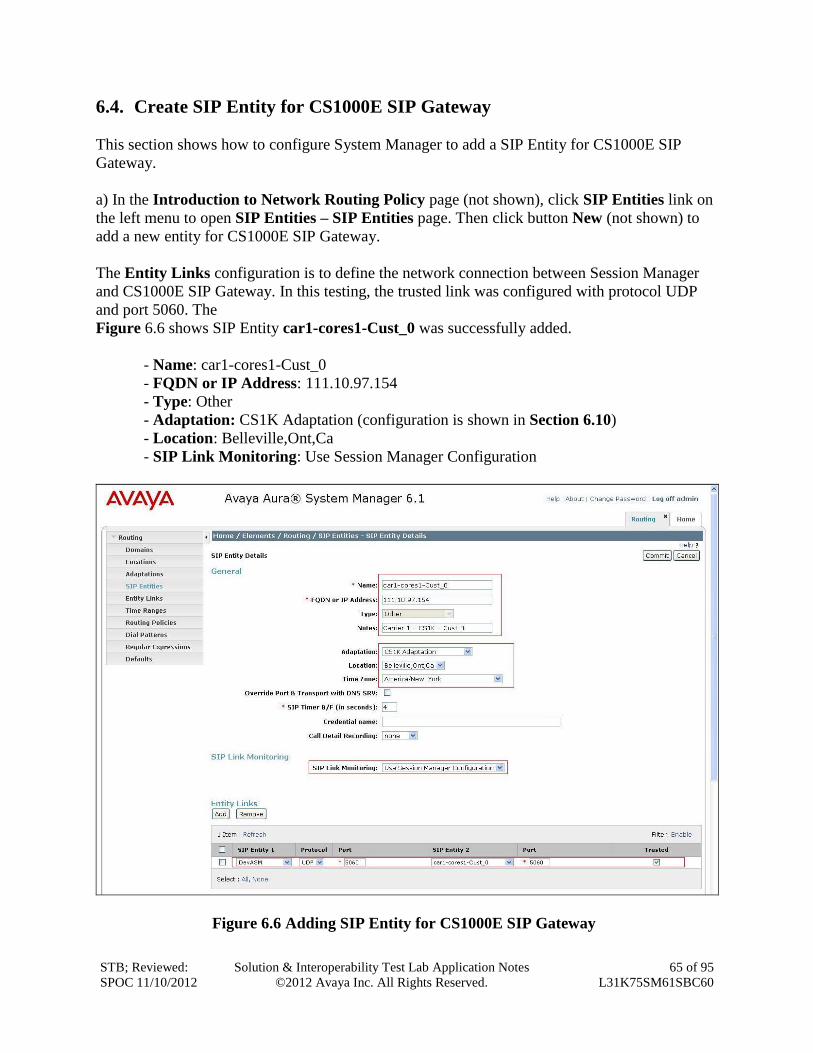
6.4. Create SIP Entity for CS1000E SIP Gateway
This section shows how to configure System Manager to add a SIP Entity for CS1000E SIP
Gateway.
a) In the Introduction to Network Routing Policy page (not shown), click SIP Entities link on
the left menu to open SIP Entities – SIP Entities page. Then click button New (not shown) to
add a new entity for CS1000E SIP Gateway.
The Entity Links configuration is to define the network connection between Session Manager
and CS1000E SIP Gateway. In this testing, the trusted link was configured with protocol UDP
and port 5060. The
Figure 6.6 shows SIP Entity car1-cores1-Cust_0 was successfully added.
- Name: car1-cores1-Cust_0
- FQDN or IP Address: 111.10.97.154
- Type: Other
- Adaptation: CS1K Adaptation (configuration is shown in Section 6.10)
- Location: Belleville,Ont,Ca
- SIP Link Monitoring: Use Session Manager Configuration
Figure 6.6 Adding SIP Entity for CS1000E SIP Gateway
STB; Reviewed:
SPOC 11/10/2012
Solution & Interoperability Test Lab Application Notes
©2012 Avaya Inc. All Rights Reserved.
66 of 95
L31K75SM61SBC60
b) Click Commit.
Note: In the Entity Links configuration, the option “Trusted” is mandatory.
6.5. Create SIP Entity for Avaya Aura® Packet SBC
This section shows how to configure System Manager to add a SIP Entity for Avaya Aura®
SBC.
a) In the Introduction to Network Routing Policy page (not shown), click SIP Entities link on
the left menu to open SIP Entities – SIP Entities page. Then click button New (not shown) to
add a new entity for Avaya Aura® SBC.
The Entity Links configuration is to define the network connection between Session Manager
and Avaya Aura® SBC. In this testing, the trusted link was configured with protocol UDP and
port 5060. The
Figure 6.7 shows SIP Entity AA-SBC was successfully added.
- Name: AA-SBC
- FQDN or IP Address: 111.10.97.206
- Type: Other
- Adaptation: Diversion for Level 3 (configuration is shown in Section 6.10)
- Location: Belleville,Ont,Ca
- SIP Link Monitoring: Use Session Manager Configuration
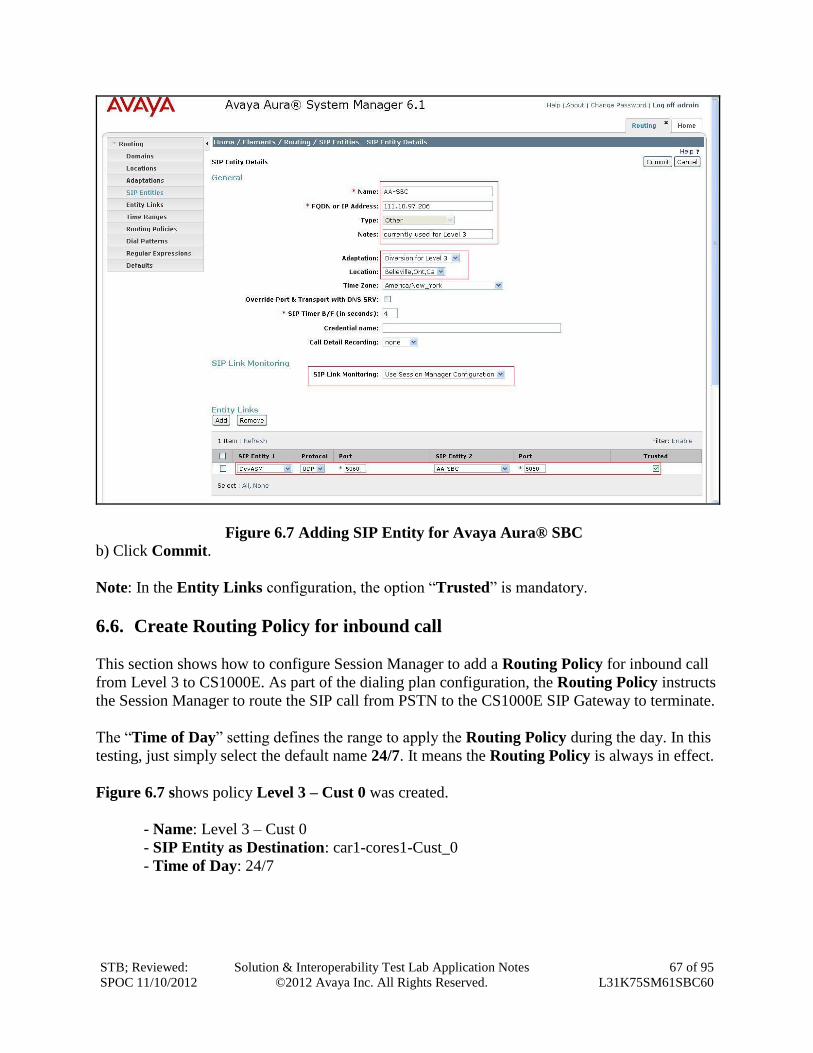
STB; Reviewed:
SPOC 11/10/2012
Solution & Interoperability Test Lab Application Notes
©2012 Avaya Inc. All Rights Reserved.
67 of 95
L31K75SM61SBC60
Figure 6.7 Adding SIP Entity for Avaya Aura® SBC
b) Click Commit.
Note: In the Entity Links configuration, the option “Trusted” is mandatory.
6.6. Create Routing Policy for inbound call
This section shows how to configure Session Manager to add a Routing Policy for inbound call
from Level 3 to CS1000E. As part of the dialing plan configuration, the Routing Policy instructs
the Session Manager to route the SIP call from PSTN to the CS1000E SIP Gateway to terminate.
The “Time of Day” setting defines the range to apply the Routing Policy during the day. In this
testing, just simply select the default name 24/7. It means the Routing Policy is always in effect.
Figure 6.7 shows policy Level 3 – Cust 0 was created.
- Name: Level 3 – Cust 0
- SIP Entity as Destination: car1-cores1-Cust_0
- Time of Day: 24/7
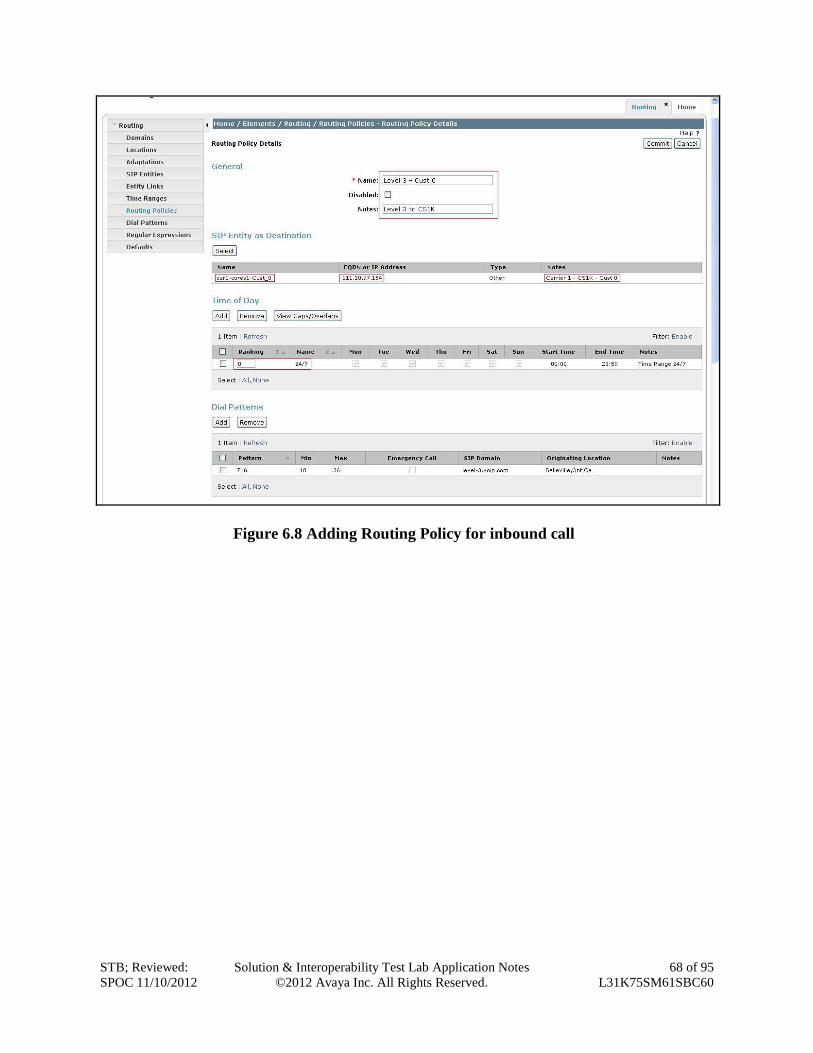
STB; Reviewed:
SPOC 11/10/2012
Solution & Interoperability Test Lab Application Notes
©2012 Avaya Inc. All Rights Reserved.
68 of 95
L31K75SM61SBC60
Figure 6.8 Adding Routing Policy for inbound call
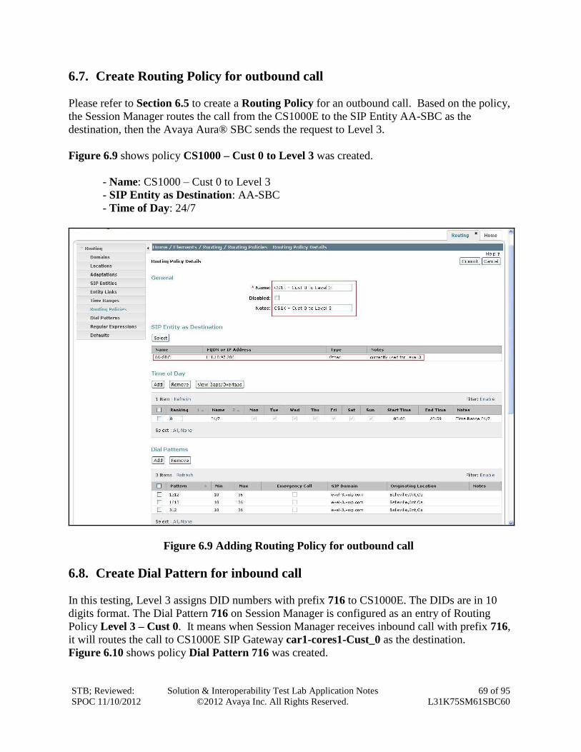
STB; Reviewed:
SPOC 11/10/2012
Solution & Interoperability Test Lab Application Notes
©2012 Avaya Inc. All Rights Reserved.
69 of 95
L31K75SM61SBC60
6.7. Create Routing Policy for outbound call
Please refer to Section 6.5 to create a Routing Policy for an outbound call. Based on the policy,
the Session Manager routes the call from the CS1000E to the SIP Entity AA-SBC as the
destination, then the Avaya Aura® SBC sends the request to Level 3.
Figure 6.9 shows policy CS1000 – Cust 0 to Level 3 was created.
- Name: CS1000 – Cust 0 to Level 3
- SIP Entity as Destination: AA-SBC
- Time of Day: 24/7
Figure 6.9 Adding Routing Policy for outbound call
6.8. Create Dial Pattern for inbound call
In this testing, Level 3 assigns DID numbers with prefix 716 to CS1000E. The DIDs are in 10
digits format. The Dial Pattern 716 on Session Manager is configured as an entry of Routing
Policy Level 3 – Cust 0. It means when Session Manager receives inbound call with prefix 716,
it will routes the call to CS1000E SIP Gateway car1-cores1-Cust_0 as the destination.
Figure 6.10 shows policy Dial Pattern 716 was created.
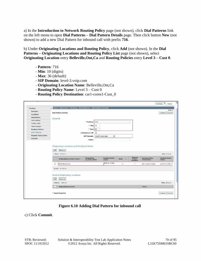
STB; Reviewed:
SPOC 11/10/2012
Solution & Interoperability Test Lab Application Notes
©2012 Avaya Inc. All Rights Reserved.
70 of 95
L31K75SM61SBC60
a) In the Introduction to Network Routing Policy page (not shown), click Dial Patterns link
on the left menu to open Dial Patterns – Dial Pattern Details page. Then click button New (not
shown) to add a new Dial Pattern for inbound call with prefix 716.
b) Under Originating Locations and Routing Policy, click Add (not shown). In the Dial
Patterns – Originating Locations and Routing Policy List page (not shown), select
Originating Location entry Belleville,Ont,Ca and Routing Policies entry Level 3 – Cust 0.
- Pattern: 716
- Min: 10 (digits)
- Max: 36 (default)
- SIP Domain: level-3.voip.com
- Originating Location Name: Belleville,Ont,Ca
- Routing Policy Name: Level 3 – Cust 0
- Routing Policy Destination: car1-cores1-Cust_0
Figure 6.10 Adding Dial Pattern for inbound call
c) Click Commit.
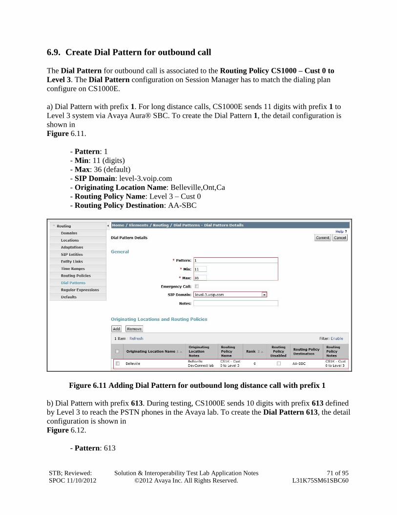
STB; Reviewed:
SPOC 11/10/2012
Solution & Interoperability Test Lab Application Notes
©2012 Avaya Inc. All Rights Reserved.
71 of 95
L31K75SM61SBC60
6.9. Create Dial Pattern for outbound call
The Dial Pattern for outbound call is associated to the Routing Policy CS1000 – Cust 0 to
Level 3. The Dial Pattern configuration on Session Manager has to match the dialing plan
configure on CS1000E.
a) Dial Pattern with prefix 1. For long distance calls, CS1000E sends 11 digits with prefix 1 to
Level 3 system via Avaya Aura® SBC. To create the Dial Pattern 1, the detail configuration is
shown in
Figure 6.11.
- Pattern: 1
- Min: 11 (digits)
- Max: 36 (default)
- SIP Domain: level-3.voip.com
- Originating Location Name: Belleville,Ont,Ca
- Routing Policy Name: Level 3 – Cust 0
- Routing Policy Destination: AA-SBC
Figure 6.11 Adding Dial Pattern for outbound long distance call with prefix 1
b) Dial Pattern with prefix 613. During testing, CS1000E sends 10 digits with prefix 613 defined
by Level 3 to reach the PSTN phones in the Avaya lab. To create the Dial Pattern 613, the detail
configuration is shown in
Figure 6.12.
- Pattern: 613
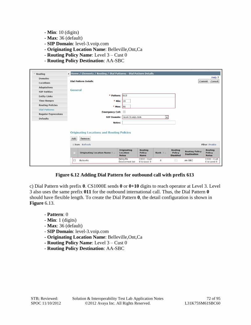
STB; Reviewed:
SPOC 11/10/2012
Solution & Interoperability Test Lab Application Notes
©2012 Avaya Inc. All Rights Reserved.
72 of 95
L31K75SM61SBC60
- Min: 10 (digits)
- Max: 36 (default)
- SIP Domain: level-3.voip.com
- Originating Location Name: Belleville,Ont,Ca
- Routing Policy Name: Level 3 – Cust 0
- Routing Policy Destination: AA-SBC
Figure 6.12 Adding Dial Pattern for outbound call with prefix 613
c) Dial Pattern with prefix 0. CS1000E sends 0 or 0+10 digits to reach operator at Level 3. Level
3 also uses the same prefix 011 for the outbound international call. Thus, the Dial Pattern 0
should have flexible length. To create the Dial Pattern 0, the detail configuration is shown in
Figure 6.13.
- Pattern: 0
- Min: 1 (digits)
- Max: 36 (default)
- SIP Domain: level-3.voip.com
- Originating Location Name: Belleville,Ont,Ca
- Routing Policy Name: Level 3 – Cust 0
- Routing Policy Destination: AA-SBC
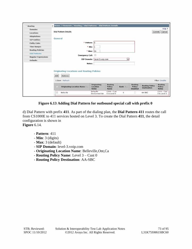
STB; Reviewed:
SPOC 11/10/2012
Solution & Interoperability Test Lab Application Notes
©2012 Avaya Inc. All Rights Reserved.
73 of 95
L31K75SM61SBC60
Figure 6.13 Adding Dial Pattern for outbound special call with prefix 0
d) Dial Pattern with prefix 411. As part of the dialing plan, the Dial Pattern 411 routes the call
from CS1000E to 411 services hosted on Level 3. To create the Dial Pattern 411, the detail
configuration is shown in
Figure 6.14.
- Pattern: 411
- Min: 3 (digits)
- Max: 3 (default)
- SIP Domain: level-3.voip.com
- Originating Location Name: Belleville,Ont,Ca
- Routing Policy Name: Level 3 – Cust 0
- Routing Policy Destination: AA-SBC
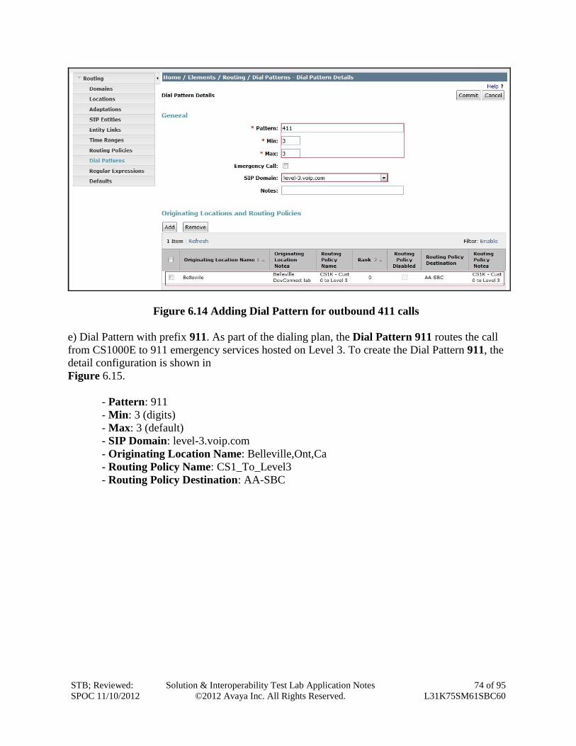
STB; Reviewed:
SPOC 11/10/2012
Solution & Interoperability Test Lab Application Notes
©2012 Avaya Inc. All Rights Reserved.
74 of 95
L31K75SM61SBC60
Figure 6.14 Adding Dial Pattern for outbound 411 calls
e) Dial Pattern with prefix 911. As part of the dialing plan, the Dial Pattern 911 routes the call
from CS1000E to 911 emergency services hosted on Level 3. To create the Dial Pattern 911, the
detail configuration is shown in
Figure 6.15.
- Pattern: 911
- Min: 3 (digits)
- Max: 3 (default)
- SIP Domain: level-3.voip.com
- Originating Location Name: Belleville,Ont,Ca
- Routing Policy Name: CS1_To_Level3
- Routing Policy Destination: AA-SBC
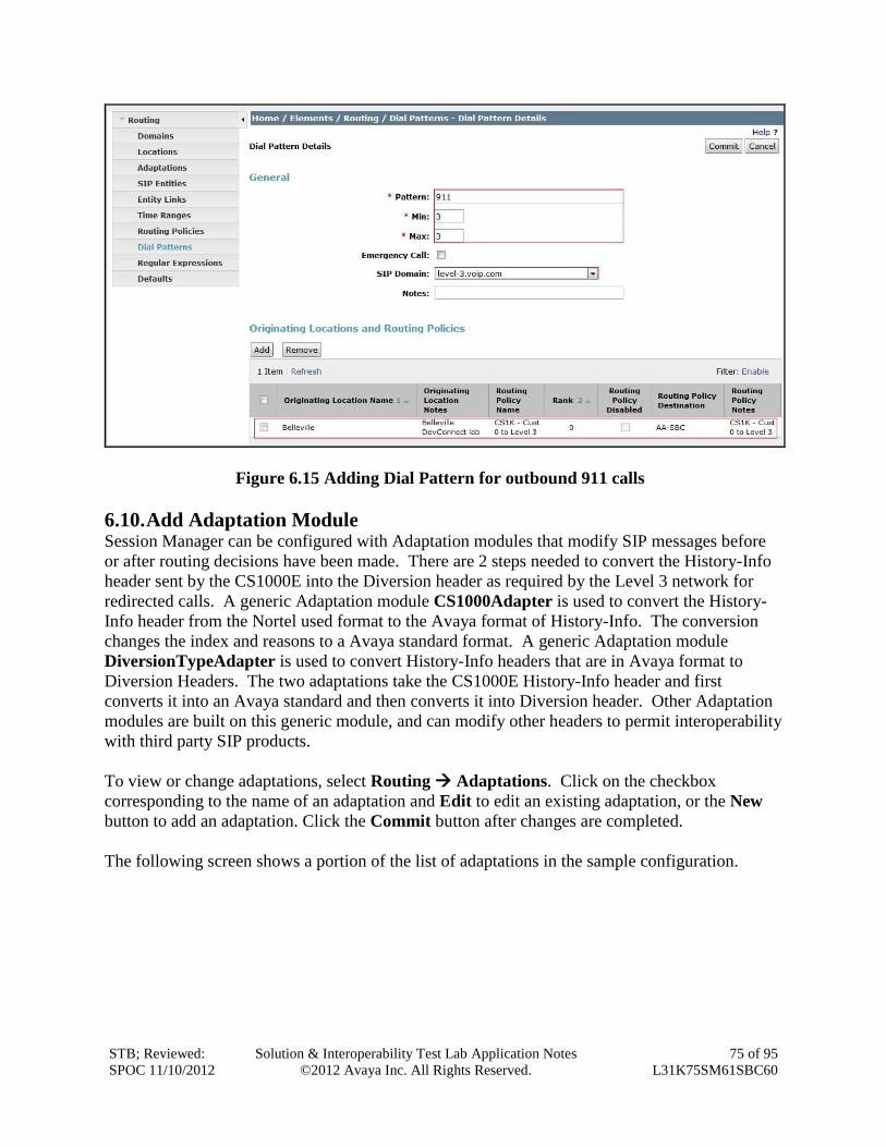
STB; Reviewed:
SPOC 11/10/2012
Solution & Interoperability Test Lab Application Notes
©2012 Avaya Inc. All Rights Reserved.
75 of 95
L31K75SM61SBC60
Figure 6.15 Adding Dial Pattern for outbound 911 calls
6.10. Add Adaptation Module Session Manager can be configured with Adaptation modules that modify SIP messages before
or after routing decisions have been made. There are 2 steps needed to convert the History-Info
header sent by the CS1000E into the Diversion header as required by the Level 3 network for
redirected calls. A generic Adaptation module CS1000Adapter is used to convert the History-
Info header from the Nortel used format to the Avaya format of History-Info. The conversion
changes the index and reasons to a Avaya standard format. A generic Adaptation module
DiversionTypeAdapter is used to convert History-Info headers that are in Avaya format to
Diversion Headers. The two adaptations take the CS1000E History-Info header and first
converts it into an Avaya standard and then converts it into Diversion header. Other Adaptation
modules are built on this generic module, and can modify other headers to permit interoperability
with third party SIP products.
To view or change adaptations, select Routing Adaptations. Click on the checkbox
corresponding to the name of an adaptation and Edit to edit an existing adaptation, or the New
button to add an adaptation. Click the Commit button after changes are completed.
The following screen shows a portion of the list of adaptations in the sample configuration.
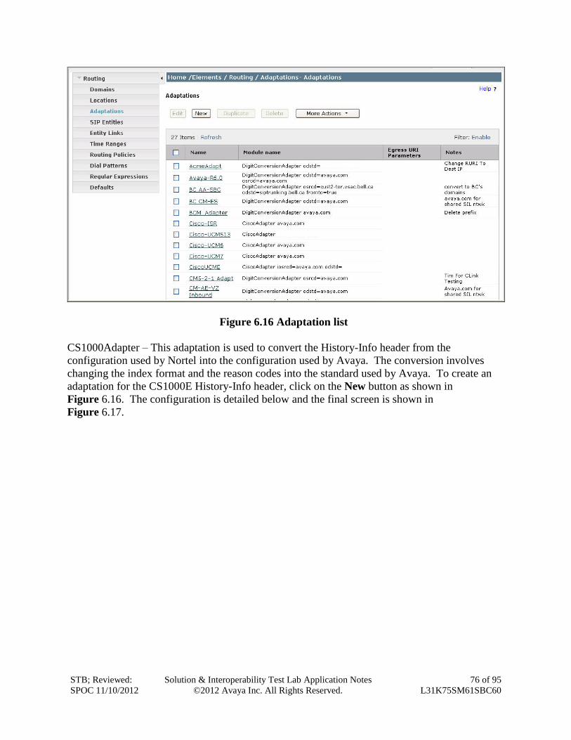
STB; Reviewed:
SPOC 11/10/2012
Solution & Interoperability Test Lab Application Notes
©2012 Avaya Inc. All Rights Reserved.
76 of 95
L31K75SM61SBC60
Figure 6.16 Adaptation list
CS1000Adapter – This adaptation is used to convert the History-Info header from the
configuration used by Nortel into the configuration used by Avaya. The conversion involves
changing the index format and the reason codes into the standard used by Avaya. To create an
adaptation for the CS1000E History-Info header, click on the New button as shown in
Figure 6.16. The configuration is detailed below and the final screen is shown in
Figure 6.17.
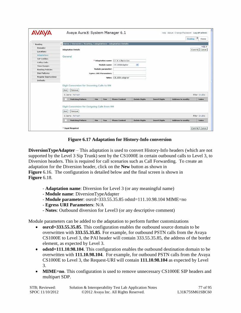
STB; Reviewed:
SPOC 11/10/2012
Solution & Interoperability Test Lab Application Notes
©2012 Avaya Inc. All Rights Reserved.
77 of 95
L31K75SM61SBC60
Figure 6.17 Adaptation for History-Info conversion
DiversionTypeAdapter – This adaptation is used to convert History-Info headers (which are not
supported by the Level 3 Sip Trunk) sent by the CS1000E in certain outbound calls to Level 3, to
Diversion headers. This is required for call scenarios such as Call Forwarding. To create an
adaptation for the Diversion header, click on the New button as shown in
Figure 6.16. The configuration is detailed below and the final screen is shown in
Figure 6.18.
- Adaptation name: Diversion for Level 3 (or any meaningful name)
- Module name: DiversionTypeAdapter
- Module parameter: osrcd=333.55.35.85 odstd=111.10.98.104 MIME=no
- Egress URI Parameters: N/A
- Notes: Outbound diversion for Level3 (or any descriptive comment)
Module parameters can be added to the adaptation to perform further customizations
osrcd=333.55.35.85. This configuration enables the outbound source domain to be
overwritten with 333.55.35.85. For example, for outbound PSTN calls from the Avaya
CS1000E to Level 3, the PAI header will contain 333.55.35.85, the address of the border
element, as expected by Level 3.
odstd=111.10.98.104. This configuration enables the outbound destination domain to be
overwritten with 111.10.98.104. For example, for outbound PSTN calls from the Avaya
CS1000E to Level 3, the Request-URI will contain 111.10.98.104 as expected by Level
3.
MIME=no. This configuration is used to remove unnecessary CS1000E SIP headers and
multipart SDP.
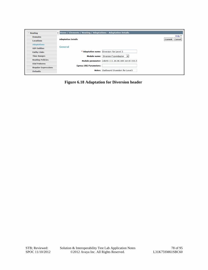
STB; Reviewed:
SPOC 11/10/2012
Solution & Interoperability Test Lab Application Notes
©2012 Avaya Inc. All Rights Reserved.
78 of 95
L31K75SM61SBC60
Figure 6.18 Adaptation for Diversion header
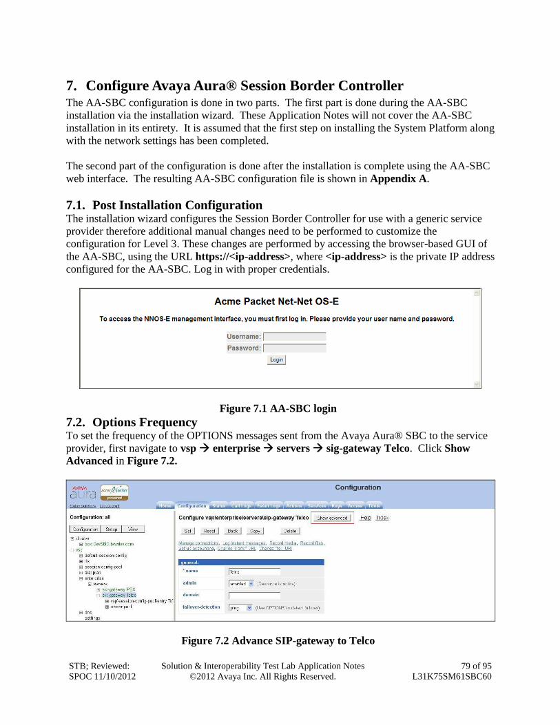
STB; Reviewed:
SPOC 11/10/2012
Solution & Interoperability Test Lab Application Notes
©2012 Avaya Inc. All Rights Reserved.
79 of 95
L31K75SM61SBC60
7. Configure Avaya Aura® Session Border Controller The AA-SBC configuration is done in two parts. The first part is done during the AA-SBC
installation via the installation wizard. These Application Notes will not cover the AA-SBC
installation in its entirety. It is assumed that the first step on installing the System Platform along
with the network settings has been completed.
The second part of the configuration is done after the installation is complete using the AA-SBC
web interface. The resulting AA-SBC configuration file is shown in Appendix A.
7.1. Post Installation Configuration The installation wizard configures the Session Border Controller for use with a generic service
provider therefore additional manual changes need to be performed to customize the
configuration for Level 3. These changes are performed by accessing the browser-based GUI of
the AA-SBC, using the URL https://<ip-address>, where <ip-address> is the private IP address
configured for the AA-SBC. Log in with proper credentials.
Figure 7.1 AA-SBC login
7.2. Options Frequency To set the frequency of the OPTIONS messages sent from the Avaya Aura® SBC to the service
provider, first navigate to vsp enterprise servers sig-gateway Telco. Click Show
Advanced in Figure 7.2.
Figure 7.2 Advance SIP-gateway to Telco
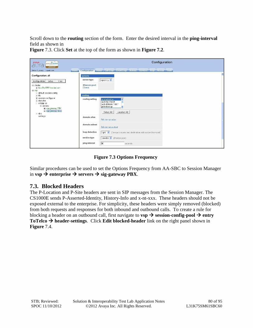
STB; Reviewed:
SPOC 11/10/2012
Solution & Interoperability Test Lab Application Notes
©2012 Avaya Inc. All Rights Reserved.
80 of 95
L31K75SM61SBC60
Scroll down to the routing section of the form. Enter the desired interval in the ping-interval
field as shown in
Figure 7.3. Click Set at the top of the form as shown in Figure 7.2.
Figure 7.3 Options Frequency
Similar procedures can be used to set the Options Frequency from AA-SBC to Session Manager
in vsp enterprise servers sig-gateway PBX.
7.3. Blocked Headers The P-Location and P-Site headers are sent in SIP messages from the Session Manager. The
CS1000E sends P-Asserted-Identity, History-Info and x-nt-xxx. These headers should not be
exposed external to the enterprise. For simplicity, these headers were simply removed (blocked)
from both requests and responses for both inbound and outbound calls. To create a rule for
blocking a header on an outbound call, first navigate to vsp session-config-pool entry
ToTelco header-settings. Click Edit blocked-header link on the right panel shown in
Figure 7.4.
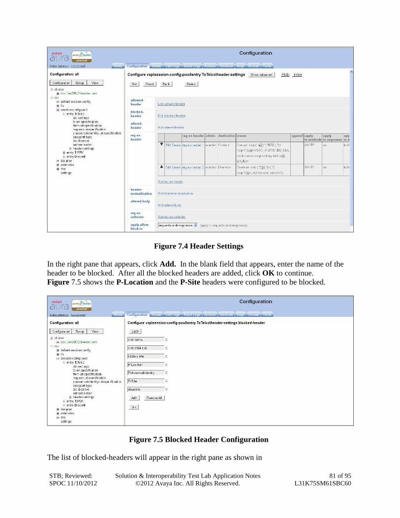
STB; Reviewed:
SPOC 11/10/2012
Solution & Interoperability Test Lab Application Notes
©2012 Avaya Inc. All Rights Reserved.
81 of 95
L31K75SM61SBC60
Figure 7.4 Header Settings
In the right pane that appears, click Add. In the blank field that appears, enter the name of the
header to be blocked. After all the blocked headers are added, click OK to continue.
Figure 7.5 shows the P-Location and the P-Site headers were configured to be blocked.
Figure 7.5 Blocked Header Configuration
The list of blocked-headers will appear in the right pane as shown in
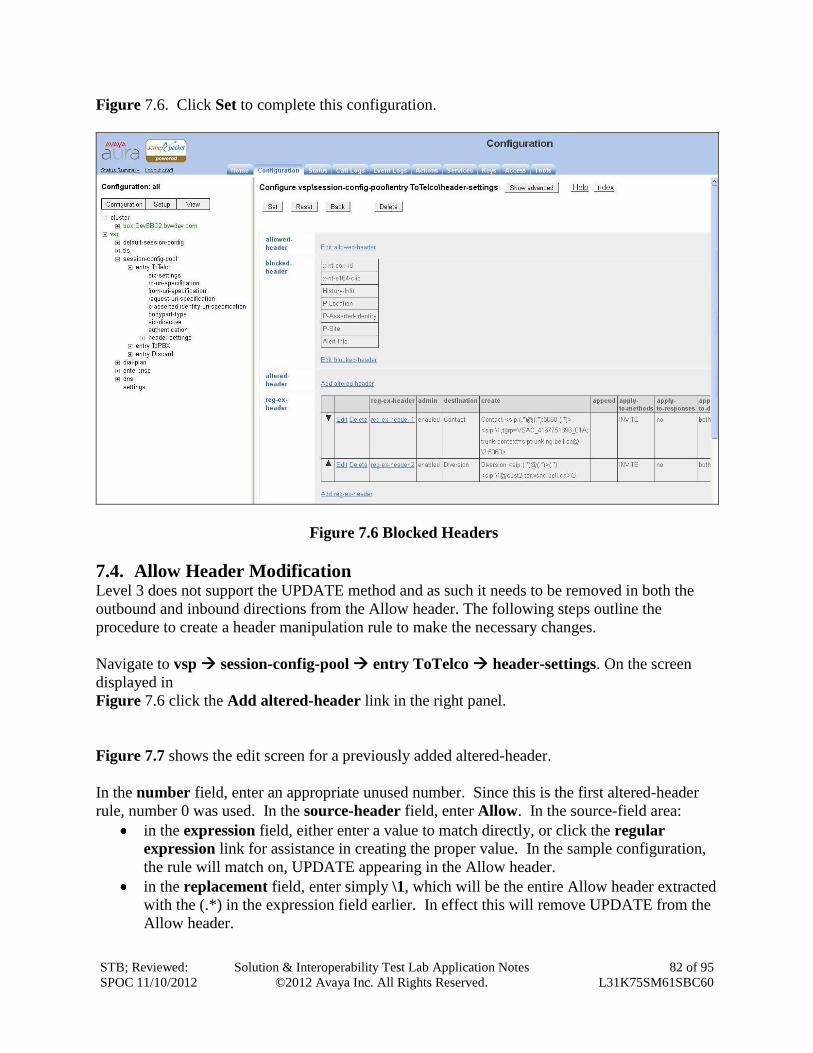
STB; Reviewed:
SPOC 11/10/2012
Solution & Interoperability Test Lab Application Notes
©2012 Avaya Inc. All Rights Reserved.
82 of 95
L31K75SM61SBC60
Figure 7.6. Click Set to complete this configuration.
Figure 7.6 Blocked Headers
7.4. Allow Header Modification Level 3 does not support the UPDATE method and as such it needs to be removed in both the
outbound and inbound directions from the Allow header. The following steps outline the
procedure to create a header manipulation rule to make the necessary changes.
Navigate to vsp session-config-pool entry ToTelco header-settings. On the screen
displayed in
Figure 7.6 click the Add altered-header link in the right panel.
Figure 7.7 shows the edit screen for a previously added altered-header.
In the number field, enter an appropriate unused number. Since this is the first altered-header
rule, number 0 was used. In the source-header field, enter Allow. In the source-field area:
in the expression field, either enter a value to match directly, or click the regular
expression link for assistance in creating the proper value. In the sample configuration,
the rule will match on, UPDATE appearing in the Allow header.
in the replacement field, enter simply \1, which will be the entire Allow header extracted
with the (.*) in the expression field earlier. In effect this will remove UPDATE from the
Allow header.
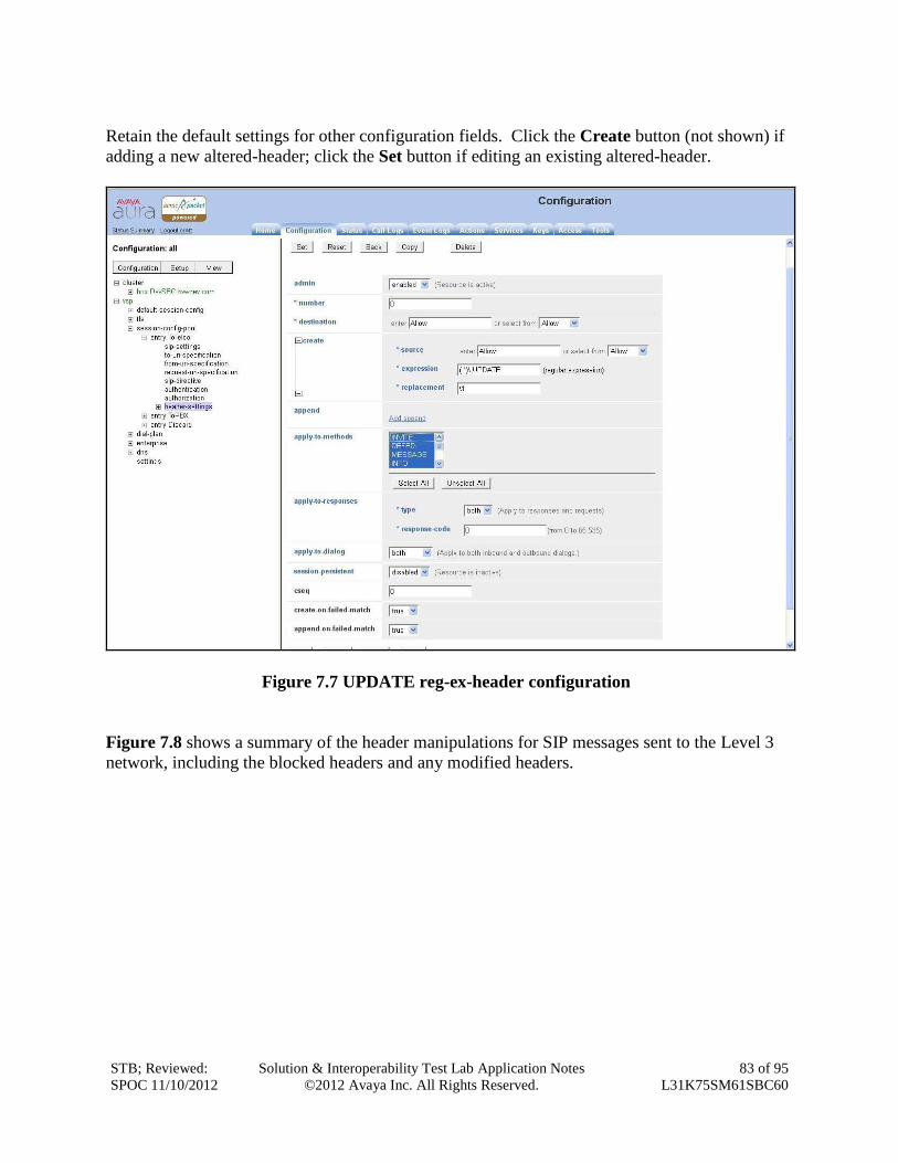
STB; Reviewed:
SPOC 11/10/2012
Solution & Interoperability Test Lab Application Notes
©2012 Avaya Inc. All Rights Reserved.
83 of 95
L31K75SM61SBC60
Retain the default settings for other configuration fields. Click the Create button (not shown) if
adding a new altered-header; click the Set button if editing an existing altered-header.
Figure 7.7 UPDATE reg-ex-header configuration
Figure 7.8 shows a summary of the header manipulations for SIP messages sent to the Level 3
network, including the blocked headers and any modified headers.
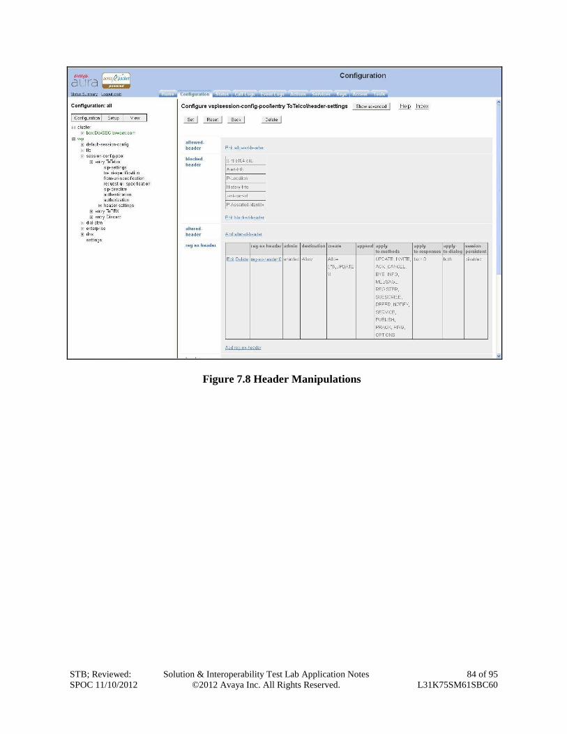
STB; Reviewed:
SPOC 11/10/2012
Solution & Interoperability Test Lab Application Notes
©2012 Avaya Inc. All Rights Reserved.
84 of 95
L31K75SM61SBC60
Figure 7.8 Header Manipulations
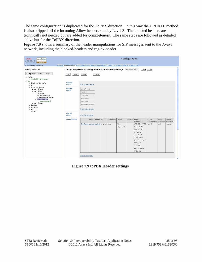
STB; Reviewed:
SPOC 11/10/2012
Solution & Interoperability Test Lab Application Notes
©2012 Avaya Inc. All Rights Reserved.
85 of 95
L31K75SM61SBC60
The same configuration is duplicated for the ToPBX direction. In this way the UPDATE method
is also stripped off the incoming Allow headers sent by Level 3. The blocked headers are
technically not needed but are added for completeness. The same steps are followed as detailed
above but for the ToPBX direction.
Figure 7.9 shows a summary of the header manipulations for SIP messages sent to the Avaya
network, including the blocked-headers and reg-ex-header.
Figure 7.9 toPBX Header settings
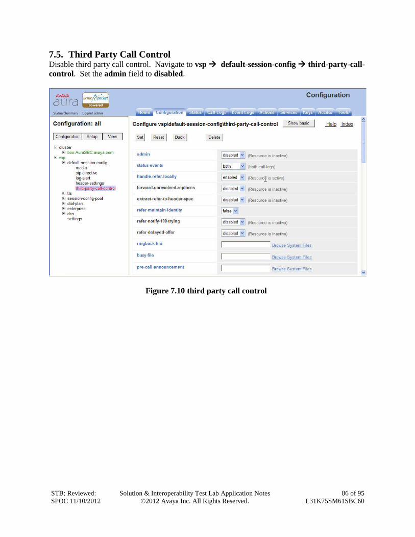
STB; Reviewed:
SPOC 11/10/2012
Solution & Interoperability Test Lab Application Notes
©2012 Avaya Inc. All Rights Reserved.
86 of 95
L31K75SM61SBC60
7.5. Third Party Call Control Disable third party call control. Navigate to vsp default-session-config third-party-call-
control. Set the admin field to disabled.
Figure 7.10 third party call control
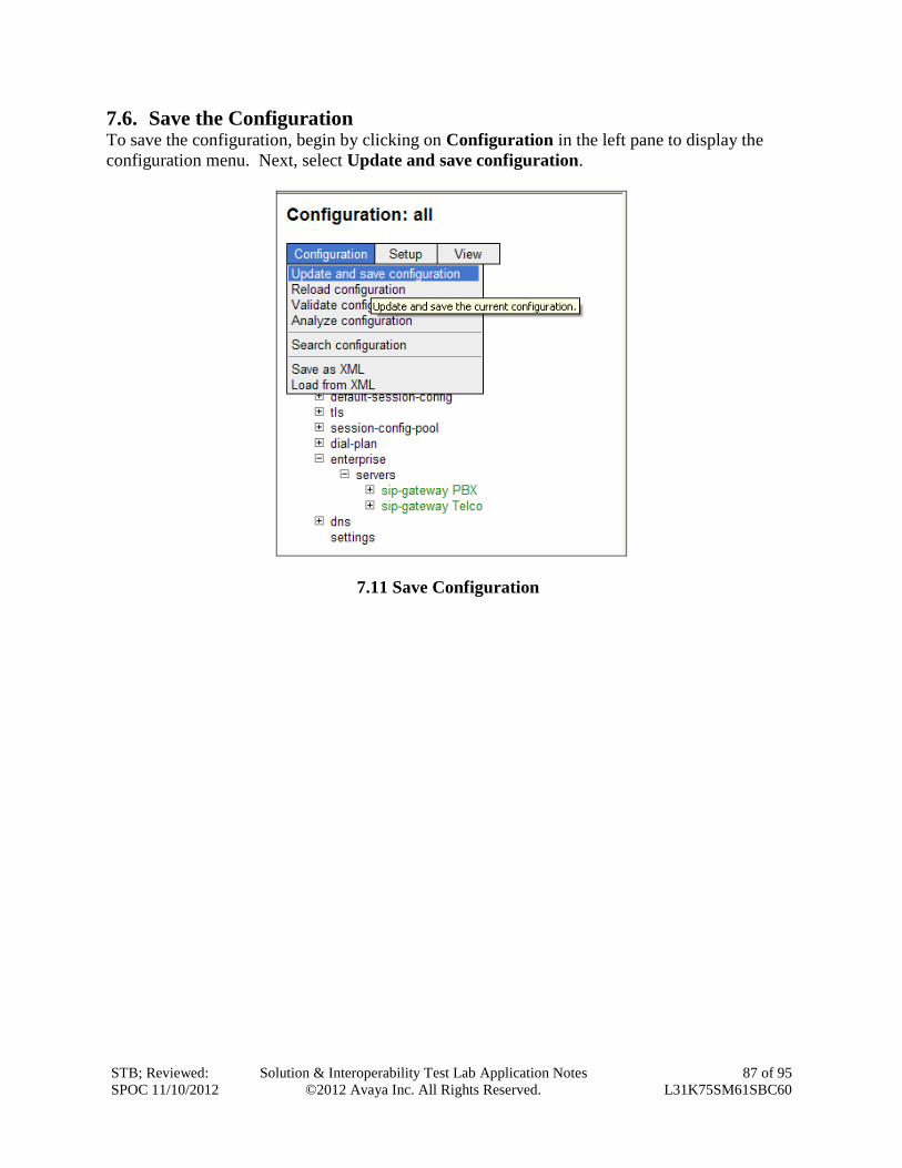
STB; Reviewed:
SPOC 11/10/2012
Solution & Interoperability Test Lab Application Notes
©2012 Avaya Inc. All Rights Reserved.
87 of 95
L31K75SM61SBC60
7.6. Save the Configuration To save the configuration, begin by clicking on Configuration in the left pane to display the
configuration menu. Next, select Update and save configuration.
7.11 Save Configuration
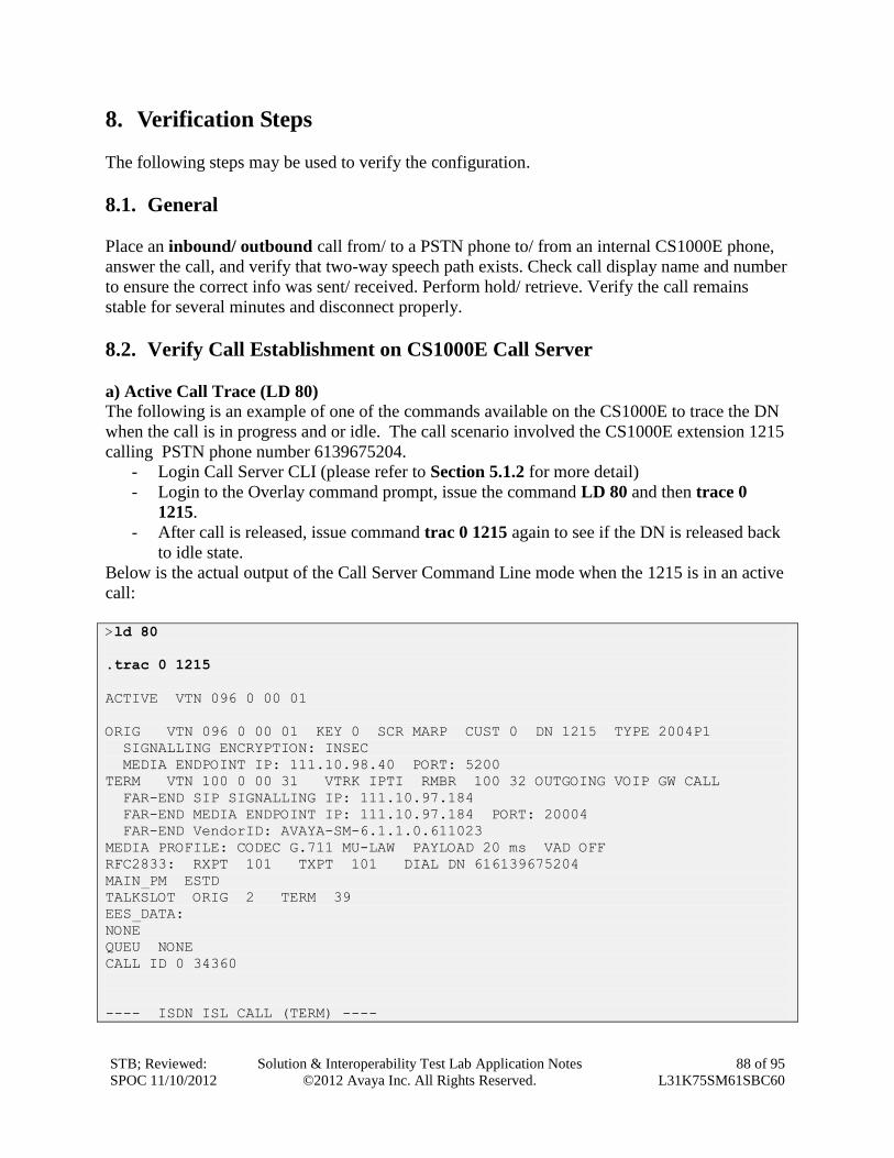
STB; Reviewed:
SPOC 11/10/2012
Solution & Interoperability Test Lab Application Notes
©2012 Avaya Inc. All Rights Reserved.
88 of 95
L31K75SM61SBC60
8. Verification Steps
The following steps may be used to verify the configuration.
8.1. General
Place an inbound/ outbound call from/ to a PSTN phone to/ from an internal CS1000E phone,
answer the call, and verify that two-way speech path exists. Check call display name and number
to ensure the correct info was sent/ received. Perform hold/ retrieve. Verify the call remains
stable for several minutes and disconnect properly.
8.2. Verify Call Establishment on CS1000E Call Server
a) Active Call Trace (LD 80)
The following is an example of one of the commands available on the CS1000E to trace the DN
when the call is in progress and or idle. The call scenario involved the CS1000E extension 1215
calling PSTN phone number 6139675204.
- Login Call Server CLI (please refer to Section 5.1.2 for more detail)
- Login to the Overlay command prompt, issue the command LD 80 and then trace 0
1215.
- After call is released, issue command trac 0 1215 again to see if the DN is released back
to idle state.
Below is the actual output of the Call Server Command Line mode when the 1215 is in an active
call:
>ld 80
.trac 0 1215
ACTIVE VTN 096 0 00 01
ORIG VTN 096 0 00 01 KEY 0 SCR MARP CUST 0 DN 1215 TYPE 2004P1
SIGNALLING ENCRYPTION: INSEC
MEDIA ENDPOINT IP: 111.10.98.40 PORT: 5200
TERM VTN 100 0 00 31 VTRK IPTI RMBR 100 32 OUTGOING VOIP GW CALL
FAR-END SIP SIGNALLING IP: 111.10.97.184
FAR-END MEDIA ENDPOINT IP: 111.10.97.184 PORT: 20004
FAR-END VendorID: AVAYA-SM-6.1.1.0.611023
MEDIA PROFILE: CODEC G.711 MU-LAW PAYLOAD 20 ms VAD OFF
RFC2833: RXPT 101 TXPT 101 DIAL DN 616139675204
MAIN_PM ESTD
TALKSLOT ORIG 2 TERM 39
EES_DATA:
NONE
QUEU NONE
CALL ID 0 34360
---- ISDN ISL CALL (TERM) ----
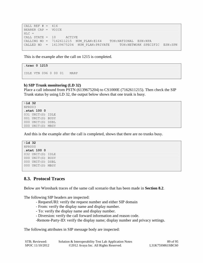
STB; Reviewed:
SPOC 11/10/2012
Solution & Interoperability Test Lab Application Notes
©2012 Avaya Inc. All Rights Reserved.
89 of 95
L31K75SM61SBC60
CALL REF # = 416
BEARER CAP = VOICE
HLC =
CALL STATE = 10 ACTIVE
CALLING NO = 7162611215 NUM_PLAN:E164 TON:NATIONAL ESN:NPA
CALLED NO = 16139675204 NUM_PLAN:PRIVATE TON:NETWORK SPECIFIC ESN:SPN
This is the example after the call on 1215 is completed.
.trac 0 1215
IDLE VTN 096 0 00 01 MARP
b) SIP Trunk monitoring (LD 32)
Place a call inbound from PSTN (6139675204) to CS1000E (7162611215). Then check the SIP
Trunk status by using LD 32, the output below shows that one trunk is busy.
>ld 32
NPR003
.stat 100 0
031 UNIT(S) IDLE
001 UNIT(S) BUSY
000 UNIT(S) DSBL
000 UNIT(S) MBSY
And this is the example after the call is completed, shows that there are no trunks busy.
>ld 32
NPR000
.stat 100 0
032 UNIT(S) IDLE
000 UNIT(S) BUSY
000 UNIT(S) DSBL
000 UNIT(S) MBSY
8.3. Protocol Traces
Below are Wireshark traces of the same call scenario that has been made in Section 8.2.
The following SIP headers are inspected:
- RequestURI: verify the request number and either SIP domain
- From: verify the display name and display number.
- To: verify the display name and display number.
- Diversion: verify the call forward information and reason code.
-Remote-Party-ID: verify the display name; display number and privacy settings.
The following attributes in SIP message body are inspected:
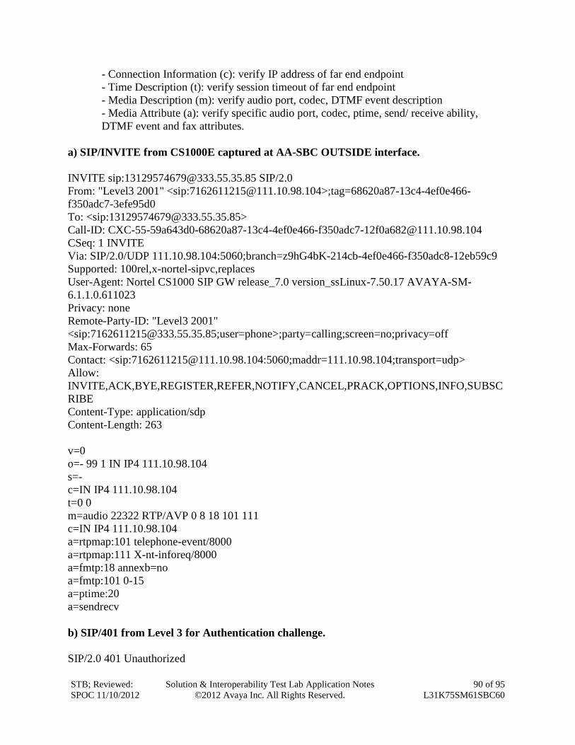
STB; Reviewed:
SPOC 11/10/2012
Solution & Interoperability Test Lab Application Notes
©2012 Avaya Inc. All Rights Reserved.
90 of 95
L31K75SM61SBC60
- Connection Information (c): verify IP address of far end endpoint
- Time Description (t): verify session timeout of far end endpoint
- Media Description (m): verify audio port, codec, DTMF event description
- Media Attribute (a): verify specific audio port, codec, ptime, send/ receive ability,
DTMF event and fax attributes.
a) SIP/INVITE from CS1000E captured at AA-SBC OUTSIDE interface.
INVITE sip:[email protected] SIP/2.0
From: "Level3 2001" <sip:[email protected]>;tag=68620a87-13c4-4ef0e466-
f350adc7-3efe95d0
To: <sip:[email protected]>
Call-ID: CXC-55-59a643d0-68620a87-13c4-4ef0e466-f350adc7-12f0a682@111.10.98.104
CSeq: 1 INVITE
Via: SIP/2.0/UDP 111.10.98.104:5060;branch=z9hG4bK-214cb-4ef0e466-f350adc8-12eb59c9
Supported: 100rel,x-nortel-sipvc,replaces
User-Agent: Nortel CS1000 SIP GW release_7.0 version_ssLinux-7.50.17 AVAYA-SM-
6.1.1.0.611023
Privacy: none
Remote-Party-ID: "Level3 2001"
<sip:[email protected];user=phone>;party=calling;screen=no;privacy=off
Max-Forwards: 65
Contact: <sip:[email protected]:5060;maddr=111.10.98.104;transport=udp>
Allow:
INVITE,ACK,BYE,REGISTER,REFER,NOTIFY,CANCEL,PRACK,OPTIONS,INFO,SUBSC
RIBE
Content-Type: application/sdp
Content-Length: 263
v=0
o=- 99 1 IN IP4 111.10.98.104
s=-
c=IN IP4 111.10.98.104
t=0 0
m=audio 22322 RTP/AVP 0 8 18 101 111
c=IN IP4 111.10.98.104
a=rtpmap:101 telephone-event/8000
a=rtpmap:111 X-nt-inforeq/8000
a=fmtp:18 annexb=no
a=fmtp:101 0-15
a=ptime:20
a=sendrecv
b) SIP/401 from Level 3 for Authentication challenge.
SIP/2.0 401 Unauthorized
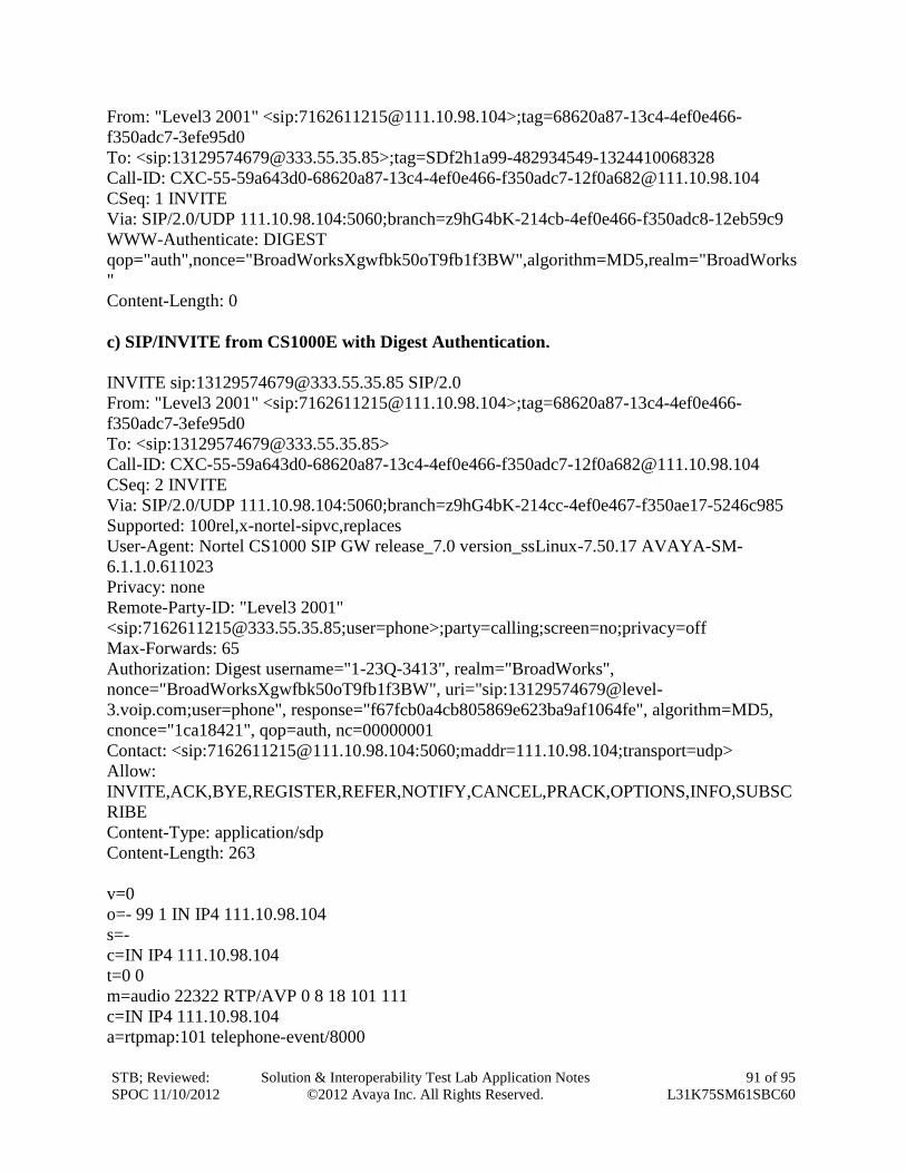
STB; Reviewed:
SPOC 11/10/2012
Solution & Interoperability Test Lab Application Notes
©2012 Avaya Inc. All Rights Reserved.
91 of 95
L31K75SM61SBC60
From: "Level3 2001" <sip:[email protected]>;tag=68620a87-13c4-4ef0e466-
f350adc7-3efe95d0
To: <sip:[email protected]>;tag=SDf2h1a99-482934549-1324410068328
Call-ID: CXC-55-59a643d0-68620a87-13c4-4ef0e466-f350adc7-12f0a682@111.10.98.104
CSeq: 1 INVITE
Via: SIP/2.0/UDP 111.10.98.104:5060;branch=z9hG4bK-214cb-4ef0e466-f350adc8-12eb59c9
WWW-Authenticate: DIGEST
qop="auth",nonce="BroadWorksXgwfbk50oT9fb1f3BW",algorithm=MD5,realm="BroadWorks
"
Content-Length: 0
c) SIP/INVITE from CS1000E with Digest Authentication.
INVITE sip:[email protected] SIP/2.0
From: "Level3 2001" <sip:[email protected]>;tag=68620a87-13c4-4ef0e466-
f350adc7-3efe95d0
To: <sip:[email protected]>
Call-ID: CXC-55-59a643d0-68620a87-13c4-4ef0e466-f350adc7-12f0a682@111.10.98.104
CSeq: 2 INVITE
Via: SIP/2.0/UDP 111.10.98.104:5060;branch=z9hG4bK-214cc-4ef0e467-f350ae17-5246c985
Supported: 100rel,x-nortel-sipvc,replaces
User-Agent: Nortel CS1000 SIP GW release_7.0 version_ssLinux-7.50.17 AVAYA-SM-
6.1.1.0.611023
Privacy: none
Remote-Party-ID: "Level3 2001"
<sip:[email protected];user=phone>;party=calling;screen=no;privacy=off
Max-Forwards: 65
Authorization: Digest username="1-23Q-3413", realm="BroadWorks",
nonce="BroadWorksXgwfbk50oT9fb1f3BW", uri="sip:13129574679@level-
3.voip.com;user=phone", response="f67fcb0a4cb805869e623ba9af1064fe", algorithm=MD5,
cnonce="1ca18421", qop=auth, nc=00000001
Contact: <sip:[email protected]:5060;maddr=111.10.98.104;transport=udp>
Allow:
INVITE,ACK,BYE,REGISTER,REFER,NOTIFY,CANCEL,PRACK,OPTIONS,INFO,SUBSC
RIBE
Content-Type: application/sdp
Content-Length: 263
v=0
o=- 99 1 IN IP4 111.10.98.104
s=-
c=IN IP4 111.10.98.104
t=0 0
m=audio 22322 RTP/AVP 0 8 18 101 111
c=IN IP4 111.10.98.104
a=rtpmap:101 telephone-event/8000
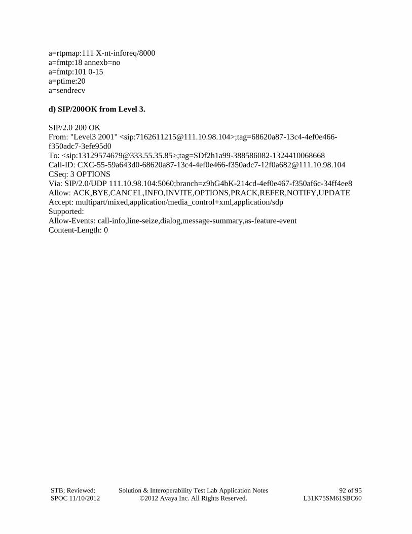
STB; Reviewed:
SPOC 11/10/2012
Solution & Interoperability Test Lab Application Notes
©2012 Avaya Inc. All Rights Reserved.
92 of 95
L31K75SM61SBC60
a=rtpmap:111 X-nt-inforeq/8000
a=fmtp:18 annexb=no
a=fmtp:101 0-15
a=ptime:20
a=sendrecv
d) SIP/200OK from Level 3.
SIP/2.0 200 OK
From: "Level3 2001" <sip:[email protected]>;tag=68620a87-13c4-4ef0e466-
f350adc7-3efe95d0
To: <sip:[email protected]>;tag=SDf2h1a99-388586082-1324410068668
Call-ID: CXC-55-59a643d0-68620a87-13c4-4ef0e466-f350adc7-12f0a682@111.10.98.104
CSeq: 3 OPTIONS
Via: SIP/2.0/UDP 111.10.98.104:5060;branch=z9hG4bK-214cd-4ef0e467-f350af6c-34ff4ee8
Allow: ACK,BYE,CANCEL,INFO,INVITE,OPTIONS,PRACK,REFER,NOTIFY,UPDATE
Accept: multipart/mixed,application/media_control+xml,application/sdp
Supported:
Allow-Events: call-info,line-seize,dialog,message-summary,as-feature-event
Content-Length: 0
STB; Reviewed:
SPOC 11/10/2012
Solution & Interoperability Test Lab Application Notes
©2012 Avaya Inc. All Rights Reserved.
93 of 95
L31K75SM61SBC60
9. Conclusion
These Application Notes describe the configuration necessary to connect Avaya Communication
Server 1000 7.5, Avaya Aura® Session Manager 6.1 and Avaya Aura® Session Border
Controller 6.0.2 to the Level 3 SIP Trunking service.
All of the test cases have been executed. Noting the observations seen during testing as
described in Section 2.2, the test results met the objectives outlined in Section 2.1. The Level 3
SIP Trunking service is considered compliant with Avaya Communication Server 1000 7.5,
Avaya Aura® Session Manager 6.1 and Avaya Aura® Session Border Controller 6.0.2.
STB; Reviewed:
SPOC 11/10/2012
Solution & Interoperability Test Lab Application Notes
©2012 Avaya Inc. All Rights Reserved.
94 of 95
L31K75SM61SBC60
10. Additional References This section references the documentation relevant to these Application Notes. Additional
Avaya product documentation is available at http://support.avaya.com.
[1] Network Routing Service Fundamentals, Avaya Communication Server 1000, Release 7.5,
Document Number NN43001-130, Revision 03.02, November 2010.
[2] IP Peer Networking Installation and Commissioning, Avaya Communication Server 1000,
Release 7.5, Document Number NN43001-313, Revision: 05.02, November 2010
[3] Communication Server 1000E Overview, Avaya Communication Server 1000, Release 7.5,
Document Number NN43041-110, Revision: 05.02, January 2011
[4] Communication Server 1000 Unified Communications Management Common Services
Fundamentals, Avaya Communication Server 1000, Release 7.5, Document Number NN43001-
116, Revision 05.08, January 2011
[5] Communication Server 1000 Dialing Plans Reference, Avaya Communication Server 1000,
Release 7.5, Document Number NN43001-283, Revision 05.02, November 2010
[6] Product Compatibility Reference, Avaya Communication Server 1000, Release 7.5,
Document Number NN43001-256, Revision 05.02, February 2011
[7] Installing and Configuring Avaya Aura® System Platform, Release 6.03, February 2011.
[8] Administering Avaya Aura® System Platform, Release 6, June 2010.
[9] Installing and Upgrading Avaya Aura® System Manager, Release 6.1, November 2010.
[10] Installing and Configuring Avaya Aura® Session Manager, Release 6.1, April 2011,
Number 03-603473.
[11] Administering Avaya Aura® Session Manager, Release 6.1, May 2011, Document Number
03-603324.
[12] Avaya Aura® Session Border Controller System Administration Guide, V.6.0, September
2010
STB; Reviewed:
SPOC 11/10/2012
Solution & Interoperability Test Lab Application Notes
©2012 Avaya Inc. All Rights Reserved.
95 of 95
L31K75SM61SBC60
©2012 Avaya Inc. All Rights Reserved.
Avaya and the Avaya Logo are trademarks of Avaya Inc. All trademarks identified by ® and
™ are registered trademarks or trademarks, respectively, of Avaya Inc. All other trademarks
are the property of their respective owners. The information provided in these Application
Notes is subject to change without notice. The configurations, technical data, and
recommendations provided in these Application Notes are believed to be accurate and
dependable, but are presented without express or implied warranty. Users are responsible for
their application of any products specified in these Application Notes.
Please e-mail any questions or comments pertaining to these Application Notes along with the
full title name and filename, located in the lower right corner, directly to the Avaya
DevConnect Program at [email protected].