Embed Size (px)
Citation preview
Skyworks Solutions, Inc. • Phone [781] 376-3000 • Fax [781] 376-3100 • [email protected] • www.skyworksinc.com 201019 Rev. A • Skyworks Proprietary Information • Products and Product Information are Subject to Change Without Notice. • February 26, 2009 1
SKY65120: WCDMA PA Bias Method For Lower Junction Temperature
application note
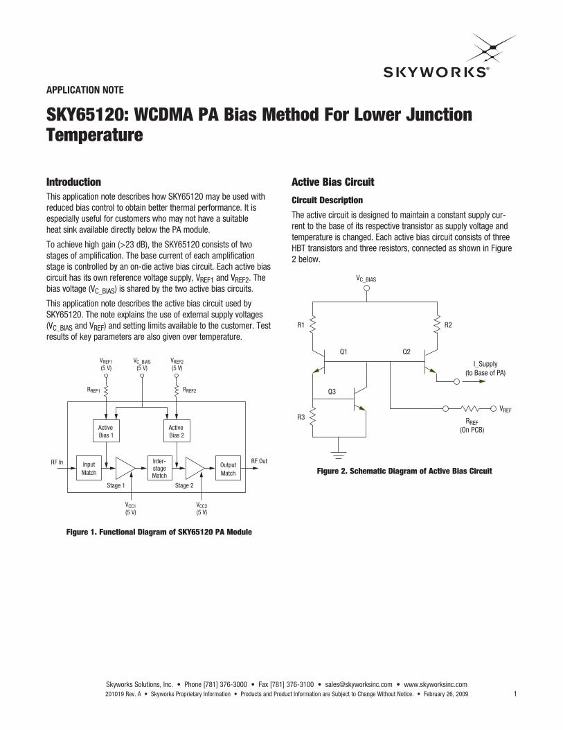
IntroductionThis application note describes how SKY65120 may be used with reduced bias control to obtain better thermal performance. It is especially useful for customers who may not have a suitable heat sink available directly below the PA module.
To achieve high gain (>23 dB), the SKY65120 consists of two stages of amplification. The base current of each amplification stage is controlled by an on-die active bias circuit. Each active bias circuit has its own reference voltage supply, VREF1 and VREF2. The bias voltage (VC_BIAS) is shared by the two active bias circuits.
This application note describes the active bias circuit used by SKY65120. The note explains the use of external supply voltages (VC_BIAS and VREF) and setting limits available to the customer. Test results of key parameters are also given over temperature.
Active Bias Circuit
Circuit Description
The active circuit is designed to maintain a constant supply cur-rent to the base of its respective transistor as supply voltage and temperature is changed. Each active bias circuit consists of three HBT transistors and three resistors, connected as shown in Figure 2 below.
Figure 1. Functional Diagram of SKY65120 PA Module
Figure 2. Schematic Diagram of Active Bias Circuit
VCC1(5 V)
VCC2(5 V)
VREF1(5 V)
RREF1 RREF2
VREF2(5 V)
VC_BIAS(5 V)
RF In RF OutInter-stageMatch
OutputMatch
Stage 1 Stage 2
Active Bias 1
Active Bias 2
InputMatch
VC_BIAS
R1
R3
Q1
Q3
Q2
R2
I_Supply(to Base of PA)
RREF(On PCB)
VREF

Skyworks Solutions, Inc. • Phone [781] 376-3000 • Fax [781] 376-3100 • [email protected] • www.skyworksinc.com February 26, 2009 • Skyworks Proprietary Information • Products and Product Information are Subject to Change Without Notice. • 201019 Rev. A
ApplicAtion note • SKY65120: WcMDA pA BiAS MethoD For loWer Junction teMperAture
2
and Q2 switches off, and effectively remove the supply current to the associated amplifier stage.
Reference resistors, RREF1 and RREF2 (located on the customer PCB) can be used to trim the base reference current. Alternately, the RREF can be fixed and VREF voltages can be modified. For VREF1 = VREF2 = 5 V, the recommended values for these refer-ence resistors are:
RREF1 = 390 Ohms,
RREF2 = 120 Ohms.
Figure 3. SKY65120 Evaluation Board Schematic
Transistor Q3 is used as a thermal reference VT monitor, and is located on-die close to the amplifier transistor. This configuration allows stable PA module operation as the amplifier temperature changes.
The main supply voltage to the bias circuits, VC_BIAS, should be set to 5 V, and is internally connected to both bias circuits.
Reference voltages, VREF1 and VREF2 are made available to the user to allow PA ON/OFF switching; and a certain amount of gain and current control. When the VREF voltages are set to zero, Q1
GND3
C1310 µF
C13300 pF
R1390 Ω
R2120 Ω
J2RF_OUT
J1RF_IN
C28.2 pF
C108.2 pF
C111500 pF
C1210 µF
C68.2 pF
C73300 pF
C810 µF
C38.2 pF
GND2
GND1
VREF1
VREF1
VREF2
VCC2
VCC2
VCC1 VCC1
N/C2
N/C3
SKY65120
N/C4
V REF
2
GND4
GND5
RF_O
UT
N/C1
VC_BIASVC_BIAS
GND8
GND7
GND6NC
5
RF_IN
11
12
13
14
15
16
10
17
9
18
8
19
7
20
6
5
4
3
2
1
Effect Of Reducing VREF
The second stage transistor consumes the most current, whereas the first stage transistor has the most impact of overall gain. Therefore, to reduce junction temperature without severely impacting module gain, it is best to modify VREF2. Table 1 below presents the results of changing VREF2 from 4.0 V to 5.0 V.
The results show maximum output power (for ACLR = -45 dBc) has only slight degradation (i.e. 0.2 dB), when VREF is reduced
from 5.0 V to 4.0 V. However, the operating current is reduced by 77 mA, and case temperature is reduced from 73 °C to 61 °C.
Note: All measurements taken at 25 °C, with the heat-sink removed from the evaluation board. All other supply voltages fixed at 5 V.

ApplicAtion note • SKY65120: WcMDA pA BiAS MethoD For loWer Junction teMperAture
Skyworks Solutions, Inc. • Phone [781] 376-3000 • Fax [781] 376-3100 • [email protected] • www.skyworksinc.com 201019 Rev. A • Skyworks Proprietary Information • Products and Product Information are Subject to Change Without Notice. • February 26, 2009 3
Table 1: Maximum POuT, Gain, ICC and Case Temperature vs. VREF2
Table 2: Maximum Junction Temperature vs. VREF (Case Temperature = 85 °C)
VreF2 (V) pin (dBm) pout (dBm) Gain (dB) icc (mA) case temp (°c)
5.0 1.95 24.8 22.85 554 72.8
4.8 1.75 24.8 23.05 527 71.6
4.5 1.55 24.8 23.25 515 69.8
4.3 1.45 24.75 23.3 504 64.1
4.0 1.25 24.6 23.35 477 61.0
Vcc1; Vcc2 (V)
Vc_BiAS (V)
VreF1 (V)
VreF2 (V)
icc1 (mA)
icc2 (mA)
icc_total (mA)
pout (dBm)
Measured peak tjmax (°c)
5 5 5.0 4.5 74 374 448 21 138
5 5 5.0 4.0 76 327 403 21 130
5 5 4.5 4.5 70 375 445 21 136
5 5 4.5 4.0 69 328 397 21 131
5 5 4.0 4.5 63 377 440 21 137
5 5 4.0 4.0 63 329 392 21 129
Figure 4. IR-scan Plot Showing Thermal Profile Across Amplifier with VREF1 = VREF2 = 4 V, Case Temperature = 85 °C, and POuT = 21 dBm
Measured Junction Temperature
IR-scans were conducted on devices with case temperature set to 85 °C, with various combinations of VREF1 and VREF2. At each setting, output power was adjusted to 21 dBm. Table 2 shows the measured maximum junction temperature at each VREF1 and VREF2 combination.
The temperature data shows the lowest junction temperature and current consumption are achieved when VREF1 = VREF2 = 4 V.
IR-scan plot for VREF1 = VREF2 = 4 V is shown in Figure 4 below.
Skyworks Solutions, Inc. • Phone [781] 376-3000 • Fax [781] 376-3100 • [email protected] • www.skyworksinc.com February 26, 2009 • Skyworks Proprietary Information • Products and Product Information are Subject to Change Without Notice. • 201019 Rev. A
ApplicAtion note • SKY65120: WcMDA pA BiAS MethoD For loWer Junction teMperAture
4
Summary and Recommendation
RF and IR-scans tests were conducted on the SKY65120 ampli-fier module to determine the best method for biasing the module to reduce case and junction temperature in conditions where a heat-sink may not be available.
The results presented shows VREF2 can be set to 4.0 V with no significant degradation of gain and ACLR performance.
The best temperature profile can be obtained with VREF1 = VREF2 = 4.0 V. With no heat-sink and case temperature to 85 °C, the maximum junction temperature was measured at 129 °C.
Note: IR-scans were done with an earlier set of the evaluation board component values than those referenced in the data sheet. While the absolute results may be different, the principles and methods described in this application note still apply. Please refer to the SKY65120 data sheet for the latest evaluation board component values.
ApplicAtion note • SKY65120: WcMDA pA BiAS MethoD For loWer Junction teMperAture
Skyworks Solutions, Inc. • Phone [781] 376-3000 • Fax [781] 376-3100 • [email protected] • www.skyworksinc.com 201019 Rev. A • Skyworks Proprietary Information • Products and Product Information are Subject to Change Without Notice. • February 26, 2009 5
Copyright © 2009, Skyworks Solutions, Inc. All Rights Reserved.
Information in this document is provided in connection with Skyworks Solutions, Inc. (“Skyworks”) products or services. These materials, including the information contained herein, are provided by Skyworks as a service to its customers and may be used for informational purposes only by the customer. Skyworks assumes no responsibility for errors or omissions in these materials or the information contained herein. Skyworks may change its documentation, products, services, specifications or product descriptions at any time, without notice. Skyworks makes no commitment to update the materials or information and shall have no responsibility whatsoever for conflicts, incompatibilities, or other difficulties arising from any future changes. No license, whether express, implied, by estoppel or otherwise, is granted to any intellectual property rights by this document. Skyworks assumes no liability for any materials, products or information provided hereunder, including the sale, distribution, reproduction or use of Skyworks products, information or materials, except as may be provided in Skyworks Terms and Conditions of Sale.
THE MATERIALS, PRODUCTS AND INFORMATION ARE PROVIDED “AS IS” WITHOUT WARRANTY OF ANY KIND, WHETHER EXPRESS, IMPLIED, STATUTORY, OR OTHERWISE, INCLUDING FITNESS FOR A PARTICULAR PURPOSE OR USE, MERCHANTABILITY, PERFORMANCE, QUALITY OR NON-INFRINGEMENT OF ANY INTELLECTUAL PROPERTY RIGHT; ALL SUCH WARRANTIES ARE HEREBY EXPRESSLY DISCLAIMED. SKYWORKS DOES NOT WARRANT THE ACCURACY OR COMPLETENESS OF THE INFORMATION, TEXT, GRAPHICS OR OTHER ITEMS CONTAINED WITHIN THESE MATERIALS. SKYWORKS SHALL NOT BE LIABLE FOR ANY DAMAGES, INCLUDING BUT NOT LIMITED TO ANY SPECIAL, INDIRECT, INCIDENTAL, STATUTORY, OR CONSEQUENTIAL DAMAGES, INCLUDING WITHOUT LIMITATION, LOST REVENUES OR LOST PROFITS THAT MAY RESULT FROM THE USE OF THE MATERIALS OR INFORMATION, WHETHER OR NOT THE RECIPIENT OF MATERIALS HAS BEEN ADVISED OF THE POSSIBILITY OF SUCH DAMAGE.
Skyworks products are not intended for use in medical, lifesaving or life-sustaining applications, or other equipment in which the failure of the Skyworks products could lead to personal injury, death, physical or environmental damage. Skyworks customers using or selling Skyworks products for use in such applications do so at their own risk and agree to fully indemnify Skyworks for any damages resulting from such improper use or sale.
Customers are responsible for their products and applications using Skyworks products, which may deviate from published specifications as a result of design defects, errors, or operation of products outside of published parameters or design specifications. Customers should include design and operating safeguards to minimize these and other risks. Skyworks assumes no liability for applications assistance, customer product design, or damage to any equipment resulting from the use of Skyworks products outside of stated published specifications or parameters.
Skyworks, the Skyworks symbol, and “Breakthrough Simplicity” are trademarks or registered trademarks of Skyworks Solutions, Inc., in the United States and other countries. Third-party brands and names are for identification purposes only, and are the property of their respective owners. Additional information, including relevant terms and conditions, posted at www.skyworksinc.com, are incorporated by reference.